

Welcome
Congratulations on your purchase of a new
Honda vehicle. Your selection of a Honda
makes you part of a worldwide family of
satisfied customers who appreciate
Honda’s reputation for building quality into
every product.
To ensure your safety and riding pleasure:
● Read this owner’s manual carefully.
● Follow all recommendations and
procedures contained in this manual.
● Pay close attention to safety messages
contained in this manual and on the
vehicle.
To protect your investment, we urge you to
take responsibility for keeping your vehicle
well serviced and maintained.
Also, observe the break-in guidelines, and
always perform the pre-ride inspection and
other periodic checks in this manual.
When service is required, remember that
your Honda dealer knows your vehicle best.
If you have the required mechanical
“know-how” and tools, you can purchase
an official Honda Service Manual to help
you perform many maintenance and repair
tasks.
2 P. 232
Read the warranty information thoroughly
so that you understand the warranty
coverage and that you are aware of your
rights and responsibilities.
2 P. 233
You may also want to visit our website at
www.powersports.honda.com.
www.honda.ca.
Happy riding!
California Perchlorate Contamination
Prevention Act
CR type batteries in this vehicle may contain
perchlorate materials - special handling may
apply. See www.dtsc.ca.gov/hazardouswaste/
perchlorate/
Canada
A Few Words About Safety
Your safety, and the safety of others, is very
important. Operating this vehicle safely is
an important responsibility.
To help you make informed decisions about
safety, we have provided operating
procedures and other information on safety
labels and in this manual. This information
alerts you to potential hazards that could
hurt you or others.
Of course, it is not practical or possible to
warn you about all hazards associated with
operating or maintaining a vehicle. You
must use your own good judgment.
You will find important safety information
in a variety of forms, including:
● Safety labels on the vehicle
● Safety Messages preceded by a safety
alert symbol and one of three signal
words: DANGER, WARNING, or
CAUTION.
These signal words mean:
DANGER
You WILL be KILLED or SERIOUSLY
HURT if you don’t follow instructions.
WARNING
You CAN be KILLED or SERIOUSLY
HURT if you don’t follow instructions.
CAUTION
You CAN be HURT if you don’t follow
instructions.
Other important information is
provided under the following
titles:
NOTICE
Information to help you avoid
damage to your vehicle, other
property, or the environment.

Vehicle Safety
This section contains important information for safe riding of your vehicle.
Please read this section carefully.
Safety Guidelines ..................................... P. 3
Safety Labels ............................................ P. 6
Safety Precautions ................................. P. 10
Riding Precautions ................................. P. 13
Accessories & Modifications.................. P. 17
Loading ................................................... P. 17
Safety Guidelines
3
Vehicle Safety
Safety Guidelines
Follow these guidelines to enhance your
safety:
● Perform all routine and regular
inspections specified in this manual.
● Stop the engine and keep sparks and
flame away before filling the fuel tank.
● Do not run the engine in enclosed or
partly enclosed areas. Carbon monoxide
in exhaust gases is toxic and can kill you.
● Do not ride the vehicle with the mirrors
folded inward, as the mirrors can
interfere with the handlebar controls.
It’s a proven fact: helmets and protective
apparel significantly reduce the number
and severity of head and other injuries. So
always wear an approved helmet and
protective apparel.
2 P. 10
Make sure that you are physically fit,
mentally focused and free of alcohol and
drugs.
Check that you and your passenger are
both wearing an approved helmet and
protective apparel. Instruct your passenger
on holding onto the grab rails or your
waist, leaning with you in turns, and
keeping their feet on the step boards, even
when the vehicle is stopped.
Even if you have ridden other vehicles,
practice riding in a safe area to become
familiar with how this vehicle works and
handles, and to become accustomed to the
vehicle’s size and weight.
We recommend that all riders take a
certified course approved by the
Motorcycle Safety Foundation (MSF). New
riders should start with the basic course,
and even experienced riders will find the
advanced course beneficial.
For information about the MSF training
course nearest you, call the national toll-
free number:
(800) 446-9227.
Other riding tips can be found in the
You and Your Motorcycle Riding Tips
booklet that came with your vehicle.
WARNINGWARNING
Riding the vehicle with the mirrors
folded inward can interfere with
your ability to safely operate the
vehicle and could lead to a crash
which you can be seriously hurt or
killed.
Make sure the mirrors are fully
extended outward and secured in
place before riding the vehicle.
Always Wear a Helmet
Before Riding
Take Time to Learn & Practice
USA
continued

Safety Guidelines
4
Vehicle Safety
Always pay attention to other vehicles
around you, and do not assume that other
drivers see you. Be prepared to stop quickly
or perform an evasive maneuver.
Make yourself more visible, especially at
night, by wearing bright reflective clothing,
positioning yourself so other drivers can see
you, signaling before turning or changing
lanes, and using your horn when necessary.
Never ride beyond your personal abilities or
faster than conditions warrant. Fatigue and
inattention can impair your ability to use
good judgment and ride safely.
Alcohol and riding don’t mix. Even one
alcoholic drink can reduce your ability to
respond to changing conditions, and your
reaction time gets worse with every
additional drink. Don’t drink and ride, and
don’t let your friends drink and ride either.
It’s important to keep your vehicle properly
maintained and in safe riding condition.
Inspect your vehicle before every ride and
perform all recommended maintenance.
Never exceed load limits (
2 P. 17), and do
not modify your vehicle or install
accessories that would make your vehicle
unsafe (
2 P. 17).
Personal safety is your first priority. If you or
anyone else has been injured, take time to
assess the severity of the injuries and
whether it is safe to continue riding. Call
for emergency assistance if needed. Also
follow applicable laws and regulations if
another person or vehicle is involved in the
crash.
If you decide to continue riding, first turn
the ignition switch to OFF, and evaluate the
condition of your vehicle. Inspect for fluid
leaks, check the tightness of critical nuts
and bolts, and check the handlebars,
control levers, brakes, and wheels. Ride
slowly and cautiously.
Your vehicle may have suffered damage
that is not immediately apparent. Have
your vehicle thoroughly checked at a
qualified service facility as soon as possible.
Ride Defensively
Make Yourself Easy to See
Ride within Your Limits
Don’t Drink and Ride
Keep Your Honda in Safe Condition
If You are Involved in a Crash
Safety Guidelines
5
Vehicle Safety
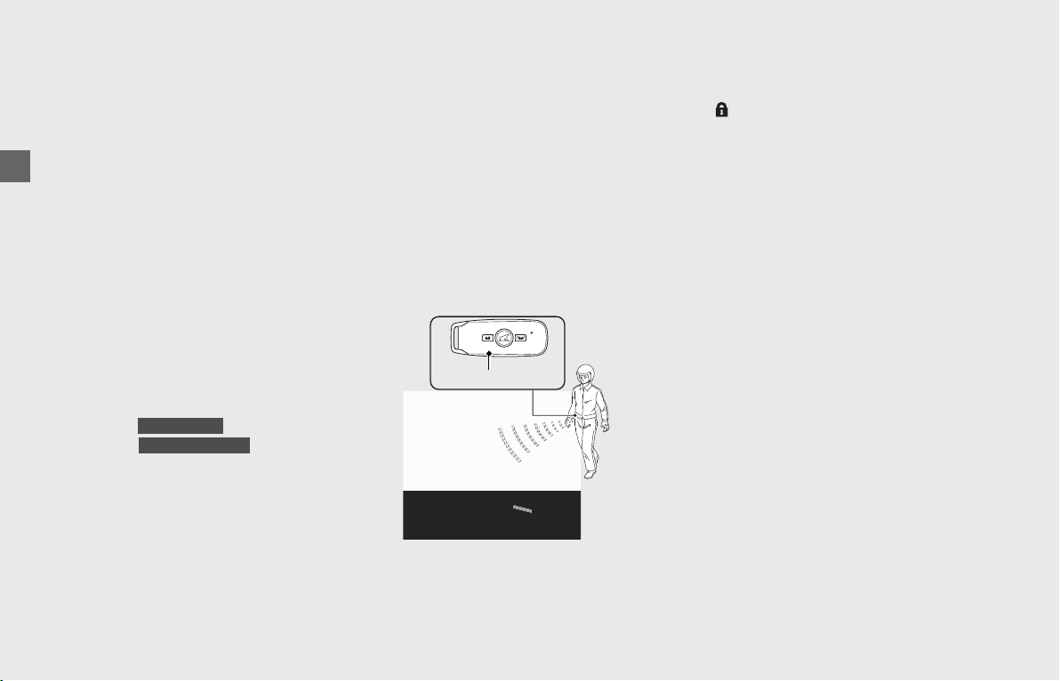
Unlike standard vehicles, or its manual
transmission sibling, the GL1800BD/D/DA
with dual clutch transmission does not have
a clutch lever that would provide you with
an additional means to control the engine
power being transmitted to the rear wheel.
Thus, in the unlikely event that you
experience a stuck throttle or other
unintended application of power to the
rear wheel, you should shut down the
engine by use of the engine stop switch
(
2 P. 52).
By moving this switch to the (Stop)
position, you will immediately stop the
engine but maintain all electrical system
functions, including lights and indicators.
Exhaust contains poisonous carbon
monoxide, a colorless, odorless gas.
Breathing carbon monoxide can cause loss
of consciousness and may lead to death.
If you run the engine in confined or even
partly enclosed area, the air you breathe
could contain a dangerous amount of
carbon monoxide.
Never run your vehicle inside a garage or
other enclosure.
Emergency Shut-down Procedure for
Vehicles Equipped with Dual Clutch
Transmission
GL1800BD/D/DA
Carbon Monoxide Hazard
WARNINGWARNING
Running the engine of your vehicle
while in an enclosed or even
partially enclosed area can cause a
rapid build-up of toxic carbon
monoxide gas.
Breathing this colorless, odorless gas
can quickly cause unconsciousness
and lead to death.
Only run your vehicle's engine when
it is located in a well ventilated area
outdoors.
Safety Labels
6
Vehicle Safety
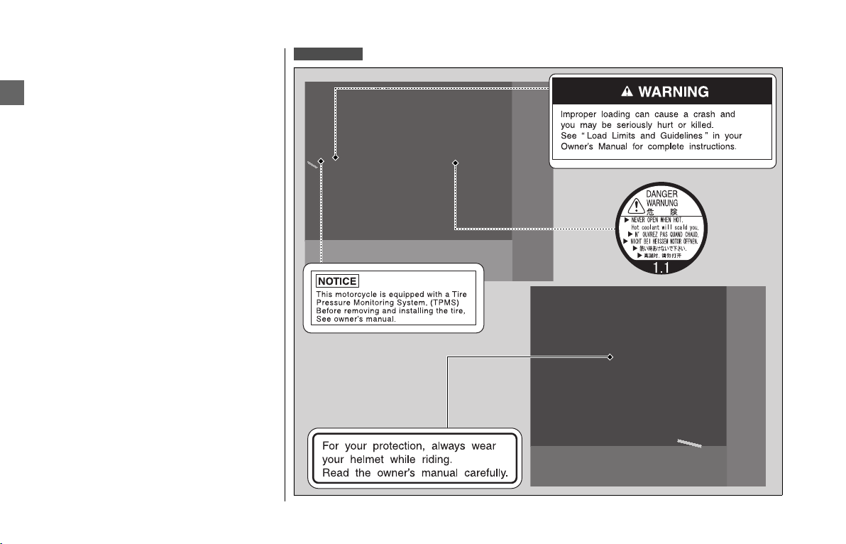
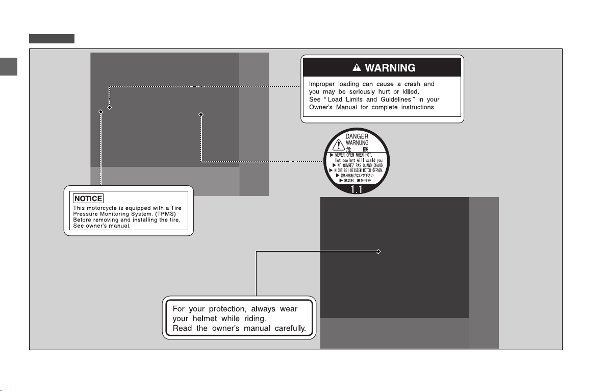
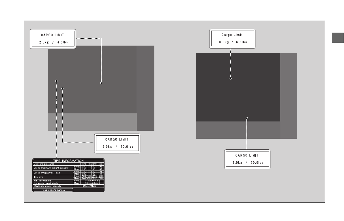
Safety Labels
Safety and information labels on your
vehicle provide important safety
information and may warn you of potential
hazards that could cause serious injury.
Read these labels carefully and don’t
remove them. If a label comes off or
becomes hard to read, contact your dealer
for a replacement.
GL1800/D/DA

Safety Labels
7
Vehicle Safety
GL1800/D
GL1800DA
GL1800DA
GL1800DA
GL1800/D
continued
Safety Labels
8
Vehicle Safety
GL1800B/BD
Safety Labels
9
Vehicle Safety
Safety Precautions
10
Vehicle Safety
Safety Precautions
● Ride cautiously and keep your hands on
the handlebars and feet on the footpegs.
● Keep passenger's hands onto the grab
rails or your waist, passenger's feet on
the step boards while riding.
● Always consider the safety of your
passenger, as well as other drivers and
riders.
Make sure that you and any passenger are
wearing an approved helmet, eye
protection, and high-visibility protective
clothing. Ride defensively in response to
weather and road conditions.
❙
Helmet
Should be safety-standard certified, high-
visibility, and correct size for your head
● Must fit comfortably but securely, with
the chin strap fastened
● Face shield with unobstructed field of
vision or other approved eye protection
Look for a DOT (Department of
Transportation) certification label on any
helmet you buy.
❙
Gloves
Full-finger leather gloves with high
abrasion resistance
❙
Boots or Riding Shoes
Sturdy boots with non-slip soles and ankle
protection
❙
Jacket and Pants
Protective, highly visible, long-sleeved
jacket and durable long pants for riding (or
a protective suit)
Protective Apparel
WARNINGWARNING
Not wearing a helmet increases the
chance of serious injury or death in a
crash.
Make sure that you and any
passenger always wear an approved
helmet and protective apparel.
USA

Safety Precautions
11
Vehicle Safety
This section describes some important safety
precautions. For airbag system components
and features, see “Airbag System.”
2 P. 64
The airbag system is an integral part of your
vehicle and is covered by your new vehicle
warranty.
The most important things you need to know
about your airbag are:
● The airbag has a limited but very important
role.
The airbag can reduce the severity of
injuries and help save your life in certain
severe frontal impacts. It cannot prevent all
injuries or deaths that can occur in a crash,
and some crashes are too severe for any
safety feature or system to prevent death.
● The airbag is designed to deploy in a severe
head-on or nearly head-on frontal impact.
The impact can be with another vehicle or
an object, such as a concrete highway
barrier. A severe frontal impact is one in
which the rider would be thrown forward
off the front of the vehicle.
● The airbag might deploy in a severe angled
frontal collision, or in a sideswipe, or if the
vehicle underrides the rear of another
vehicle.
However, because there are many variables
in a collision, the airbag might not be able
to reduce the severity of injuries to the
rider.
● The airbag might deploy if the front tire
drops into a sharp depression, such as a
pothole, or strikes a hard raised object,
such as a curb.
A brief high rate of deceleration can cause
the airbag to deploy, even though it would
not be needed.
● The airbag is designed to help protect the
rider.
It is not designed to help protect a
passenger.
● The airbag is not intended to replace a
helmet.
Helmets have proven effective in reducing
the severity of head injuries in all types of
crashes. So always wear a helmet, and
make sure a passenger wears one as well.
There are several situations in which the vehicle
airbag should not deploy. Four of the more
common situations are discussed here.
● If a rider is traveling at a moderate speed
and has a minor frontal collision, such as
running into the rear of a car slowing down
ahead, or stopped at a traffic light, the rate
of deceleration should be low enough for
the rider to either stay on the vehicle or
receive less than severe injuries to the head
or chest.
● Being struck in the side or rear by another
vehicle can result in very serious injuries.
But since the sensors are attached to the
frame, such a crash cannot be detected by
the sensors. Therefore, the airbag should
not deploy, and it would not be helpful to
the rider even if it did deploy.
● Another situation that should not result in
airbag deployment is if the vehicle slides
out and goes down on a slippery surface.
Again, the crash would not be detected or
determined to be a severe frontal impact,
and the airbag would not benefit the rider
even if it did deploy.
Airbag System
GL1800DA
continued

Safety Precautions
12
Vehicle Safety
● Finally, if the vehicle is involved in a
sideswipe with a stationary object, such as
a concrete median barrier, or with another
vehicle traveling in the same direction, as
illustrated here, the airbag should not
deploy.
❙
Important Safety Precautions
● Do not install or temporarily attach any
items, such as a map holder, over the
airbag cover or in the area between the
rider’s seat and the handlebars.
This could prevent the airbag from
deploying properly, or cause items to be
propelled by the airbag and possibly hurt
someone.
● Do not tamper with any system
components, including the wires or
connectors.
Doing so could prevent the airbag system
from operating properly or cause
unintended airbag deployment and
possibly serious injury.
● Do not attempt to remove any airbag
components — even temporarily.
This could result in unintended airbag
deployment and injury.
What you should do: Follow all
recommendations in this owner’s manual.

Riding Precautions
13
Vehicle Safety
Riding Precautions
During the first 300 miles (500 km) of
running, follow these guidelines to ensure
your vehicle’s future reliability and
performance.
● Avoid full-throttle starts and rapid
acceleration.
● Avoid hard braking and rapid down-
shifts.
● Ride conservatively.
Observe the following guidelines:
● Avoid excessively hard braking and
downshifting.
u Sudden braking can reduce the
vehicle’s stability.
u Where possible, reduce speed before
turning; otherwise you risk sliding out.
● Exercise caution on low traction surfaces.
u The tires slip more easily on such
surfaces and braking distances are
longer.
● Avoid continuous braking.
u Repeated braking, such as when
descending long, steep slopes can
seriously overheat the brakes,
reducing their effectiveness. Use
engine braking with intermittent use
of the brakes to reduce speed.
● For full braking effectiveness, operate
both the front and rear brakes together.
❙
Combined ABS
Your vehicle is equipped with a brake
system that distributes the braking force
between the front and rear brakes.
The distribution of the braking force is
applied to both front and rear brakes when
operating the lever and/or pedal.
For full braking effectiveness, operate both
the front and rear brakes together.
The brake feel changes according to the
selected riding mode.
2
P. 120
This model is also equipped with an Anti-
lock Brake System (ABS) designed to help
prevent the brakes from locking up during
hard braking.
● ABS does not reduce braking distance. In
certain circumstances, ABS may result in
a longer stopping distance.
● ABS does not function at speeds below
3 mph (5 km/h).
● The brake lever and pedal may recoil
slightly when applying the brakes. This is
normal.
● Always use the recommended tires to
ensure correct ABS operation.
Break-in Period
Brakes
continued

Riding Precautions
14
Vehicle Safety
❙
Engine Braking
Engine braking helps slow your vehicle
down when you release the throttle. For
further slowing action, downshift to a
lower gear. Use engine braking with
intermittent use of the brakes to reduce
speed when descending long, steep slopes.
❙
Wet or Rainy Conditions
Road surfaces are slippery when wet, and
wet brakes further reduce braking
efficiency.
Exercise extra caution when braking in wet
conditions.
If the brakes get wet, apply the brakes
while riding at low speed to help them dry.
If you decide to ride your vehicle in the rain,
fog, or other bad-weather conditions, ride
carefully. Wet road surfaces reduce
traction, especially in turns, and increase
stopping distances when you brake.
If the weather turns bad while you are
riding, take extra care and do not use cruise
control.
When riding in the rain, we recommend
you adjust your windscreen height below
eye level, if possible, for better visibility.
2 P. 136
Riding in Bad Weather
Riding Precautions
15
Vehicle Safety
● Park on a firm, level surface.
● If you must park on a slight incline or
loose surface, park so that the vehicle
cannot move or fall over.
● Make sure that high-temperature parts
cannot come into contact with
flammable materials.
● Do not touch the engine, muffler, brakes
and other high-temperature parts until
they cool down.
● To reduce the likelihood of theft, always
lock the handlebars (2 P. 55) and leave
your vehicle while taking the Honda
SMART Key with you. Deactivate the
Honda SMART Key system if necessary.
2 P. 56
Use of an anti-theft device is also
recommended.
❙
Parking with the Side Stand or Center
Stand
1.
Stop the engine.
2.
Using the side stand
Push the side stand down.
Slowly lean the vehicle to the left until its
weight rests on the side stand.
Using the center stand
To lower the center stand, stand on the
left side of the vehicle. Hold the left
handle grip and the left grab rail. Press
down on the tip of the center stand with
your right foot and, simultaneously, pull
up and back.
3.
Turn the handlebars fully to the left.
uTurning the handlebars to the right
reduces stability and may cause the
vehicle to fall.
4.
Turn the ignition switch to (Lock).
2 P. 55
Then, leave your vehicle while taking the
Honda SMART Key with you. Deactivate
the Honda SMART Key system if
necessary.
2 P. 56
Follow these guidelines to protect the
engine, fuel system and catalytic converter:
● Use only unleaded gasoline.
● Use recommended octane number.
Using lower octane gasoline will result in
decreased engine performance.
● Do not use fuels containing a high
concentration of alcohol.
2P. 231
● Do not use stale or contaminated
gasoline or an oil/gasoline mixture.
● Avoid getting dirt or water in the fuel
tank.
Parking
GL1800/D/DA
Refueling and Fuel Guidelines
continued

Riding Precautions
16
Vehicle Safety
When the Honda selectable torque control
(Torque Control) detects rear wheel spin
during acceleration, the system will limit
the amount of torque applied to the rear
wheel based on the Torque Control level
set according to the selected riding mode.
Torque Control will allow some wheel spin
during acceleration at the lower Torque
Control levels settings. Select a riding mode
that is appropriate for riding conditions.
2 P. 120
Torque Control does not work during
deceleration and will not prevent the rear
wheel from skidding due to engine
braking. Do not close the throttle suddenly,
especially when riding on slippery surfaces.
Torque Control may not compensate for
rough road conditions or rapid throttle
operation. Always consider road and
weather conditions, as well as your skills
and condition, when applying throttle.
If your vehicle gets stuck in mud, snow or
sand, it may be easier to free it with the
Torque Control temporarily switched off.
2 P. 31
Temporarily turning off Torque Control also
may help you maintain control and balance
when riding on off-road terrain.
Always use the recommended tires to
ensure correct Torque Control operation.
Honda Selectable Torque Control
GL1800/D/DA
Accessories & Modifications
17
Vehicle Safety
Accessories &
Modifications
We strongly advise that you do not add any
accessories that were not specifically
designed or approved for your vehicle by
Honda or make modifications to your
vehicle from its original design. Doing so
can make it unsafe.
Modifying your vehicle may also void your
warranty and make your vehicle illegal to
operate on public roads and highways.
Before deciding to install accessories on
your vehicle be certain the modification is
safe and legal.
Do not pull a trailer with, or attach a sidecar
to, your vehicle. Your vehicle was not
designed for these attachments, and their
use can seriously impair your vehicle’s
handling.
Loading
● Carrying extra weight affects your
vehicle’s handling, braking and stability.
Always ride at a safe speed for the load
you are carrying.
● Avoid carrying an excessive load and
keep within specified load limits.
Maximum weight capacity /
Maximum luggage weight
2 P. 237,
239
● Tie all luggage securely, evenly balanced
and close to the center of the vehicle.
● Do not place objects near the lights or
the muffler.
WARNINGWARNING
Improper accessories or
modifications can cause a crash in
which you can be seriously hurt or
killed.
Follow all instructions in this owner’s
manual regarding accessories and
modifications.
WARNINGWARNING
Overloading or improper loading
can cause a crash and you can be
seriously hurt or killed.
Follow all load limits and other
loading guidelines in this manual.
Operation Guide
18
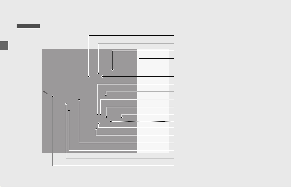
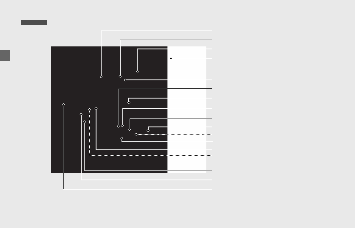
Parts Location
Throttle grip (P169)
Front brake fluid reservoir (P164)
Windscreen (P136)
Front brake lever (P171)
Rear brake fluid reservoir (P164)
Engine oil level gauge (P158)
Right fog light cover (P155)
Right cylinder head side cover (P154)
Rear brake pedal
Center stand
(P15)
Right side cover (P156)
Final drive oil drain bolt (P163)
Final drive oil fill hole cap (P163)
Seat
Fairing pocket
(P129)
Right saddlebag (P128)
GL1800/D/DA
Spark plugs (P157)
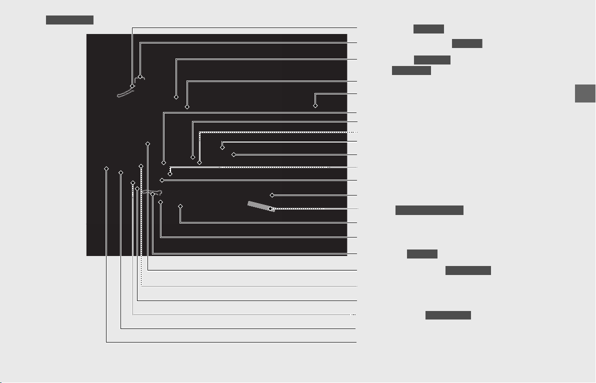
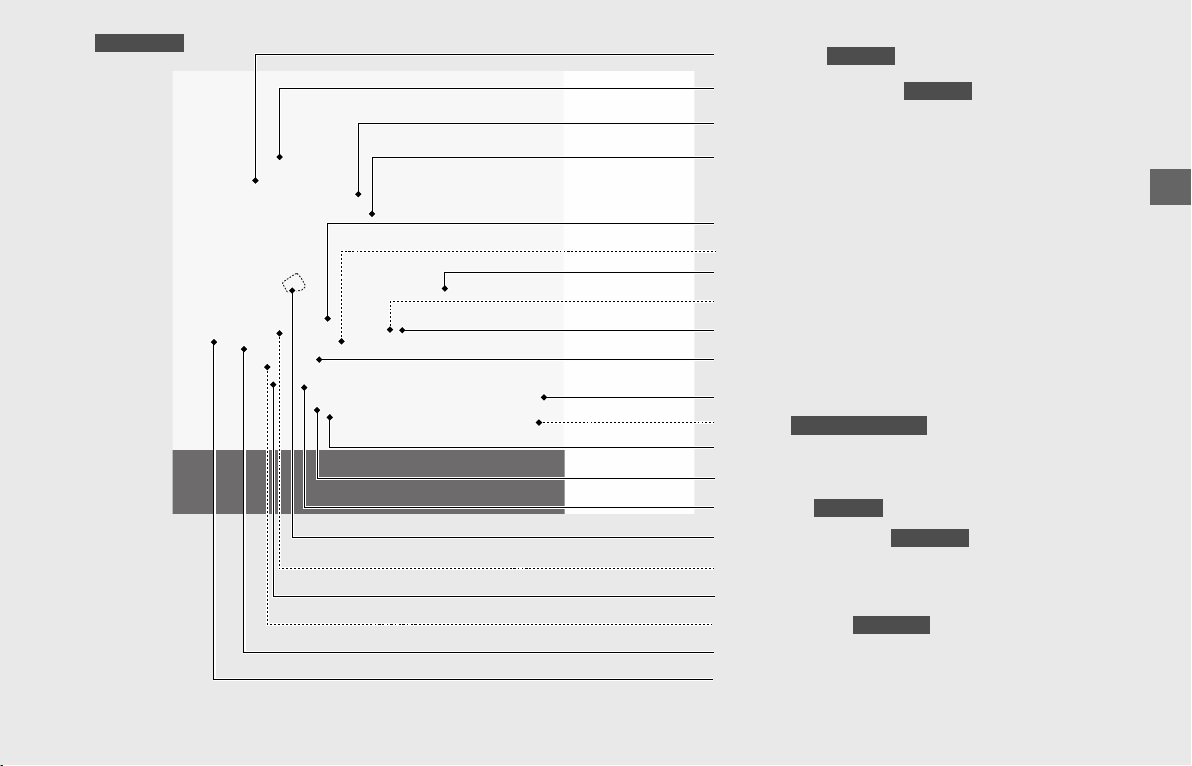
Operation Guide
19
Shelter case (P131)
Airbag (P64)
GL1800/D
GL1800DA
Fuel lid (P127)
Travel trunk (P128)
Helmet holder (P131)
Left saddlebag (P128)
Passenger seat heater switch (P134)
Side stand (P167)
Left engine side cover (P155)
Engine oil fill cap (P159)
Engine oil drain bolts (P159)
Crankcase breather tube (P170)
Parking brake lever (P60)
GL1800D/DA
GL1800/D/DA
Clutch lever (P171)
GL1800
Clutch fluid reservoir (P168)
GL1800
Shift lever (P114)
GL1800
Clutch oil filter (P161)
GL1800D/DA
Coolant reserve tank (P162)
Tool kit (P132)
Canada model only
Engine oil filter (P159)
Left fog light cover (P155)
Left cylinder head side cover (P154)
Left side cover (P156)
Battery (P153) / Fuse boxes (P209)
continued
Operation Guide
20
Throttle grip (P169)
Front brake fluid reservoir (P164)
Windscreen (P136)
Front brake lever (P171)
Rear brake fluid reservoir (P164)
Engine oil level gauge (P158)
Right fog light cover (P155)
Right cylinder head side cover (P154)
Rear brake pedal
Right side cover
(P156)
Final drive oil drain bolt (P163)
Final drive oil fill hole cap (P163)
Seat
Fairing pocket (P129)
Right saddlebag (P128)
GL1800B/BD
Rear suspension spring preload
adjuster (P173)
Spark plugs (P157)
Parts Location (Continued)
Operation Guide
21
Shelter case (P131)
Fuel lid (P127)
Helmet holder (P131)
Left saddlebag (P128)
Side stand (P167)
Left engine side cover (P155)
Engine oil fill cap (P159)
Crankcase breather tube (P170)
GL1800B/BD
Clutch lever (P171)
GL1800B
Clutch fluid reservoir (P168)
GL1800B
Parking brake lever (P60)
GL1800BD
Shift lever (P114)
GL1800B
Clutch oil filter (P161)
GL1800BD
Coolant reserve tank (P162)
Engine oil drain bolts (P159)
Tool kit (P132)
Canada model only
Engine oil filter (P159)
Left fog light cover (P155)
Left cylinder head side cover (P154)
Left side cover (P156)
Battery (P153) / Fuse boxes (P209)
Operation Guide
22
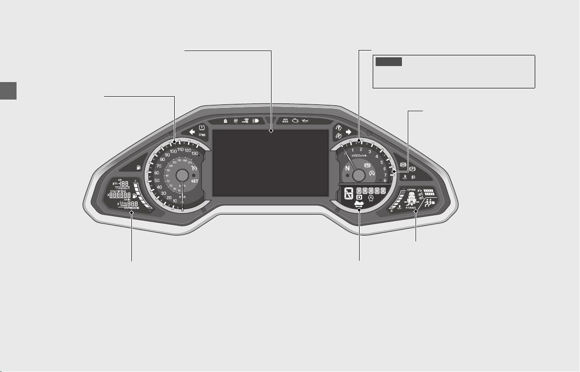
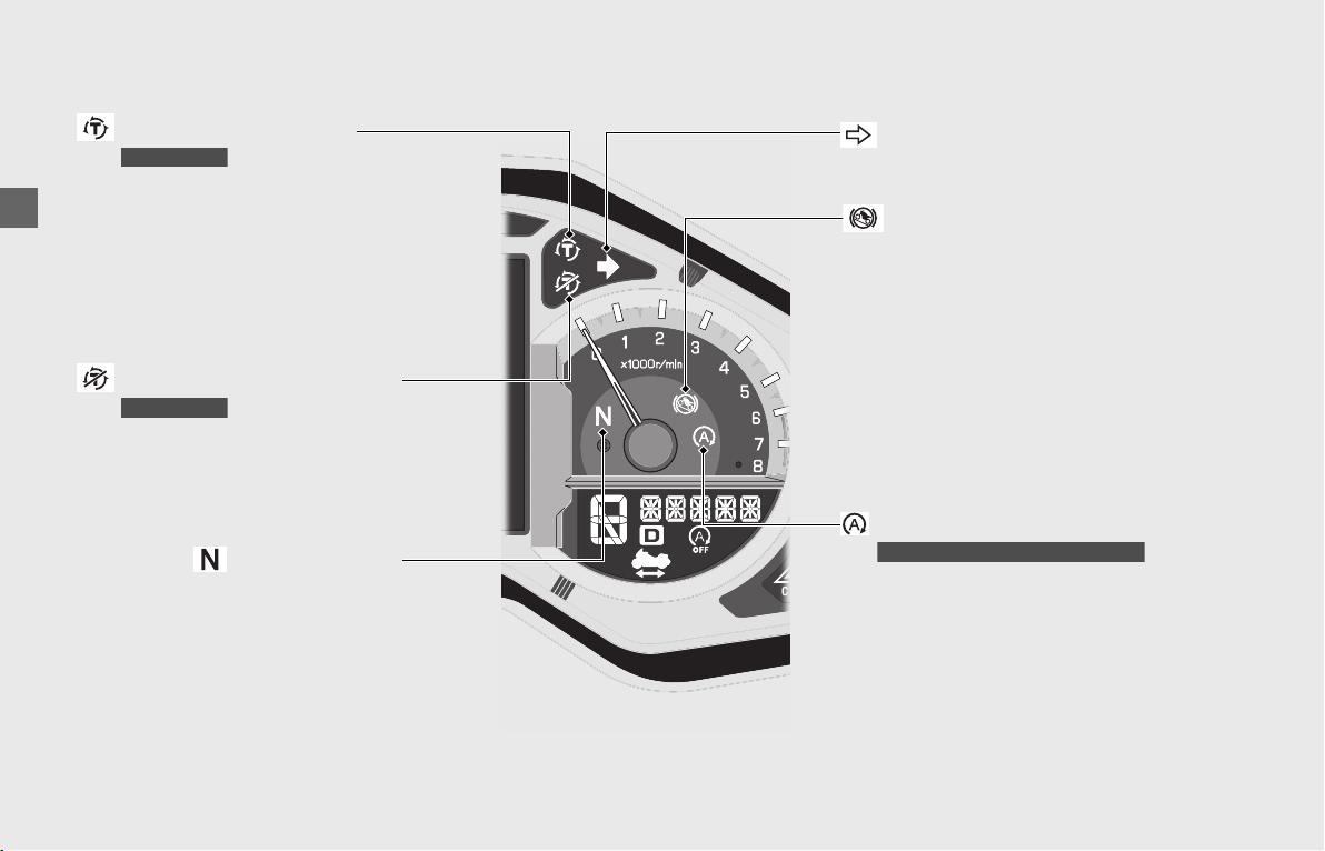
Instruments
Tachometer red zone
(excessive engine rpm range)
Speedometer
Shows riding speed in miles
per hour (mph) and kilometer
per hour (km/h).
Display Check
When the ignition switch is turned ON, all of the modes and digital segments will show on the INFO 1, INFO 2 and INFO 3 displays,
and the opening symbol will show on the multi-information display.
If the displays do not show when they should, have your dealer check for problems.
Tachometer
NOTICE
Do not operate the engine in the tachometer red zone.
Excessive engine speed can adversely affect engine life.
Multi-information display (P23)
INFO 1 display (P34) INFO 2 display (P39)
INFO 3 display (P41)
Operation Guide
23
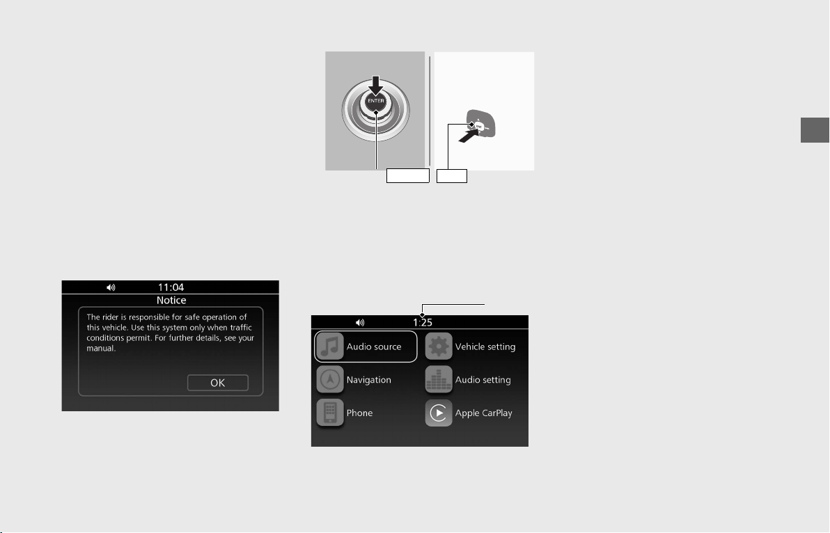
Multi-information Display
Your vehicle is equipped with a multi-
information display that presents various
functions and settings.
• Certain manual functions and settings
are disabled or inoperable while the
vehicle is in motion. You cannot select a
grayed-out menu until the vehicle is
stopped.
When the ignition switch is turned ON or
ACC, the Notice message appears on the
screen for a few second.
Read the Notice message.
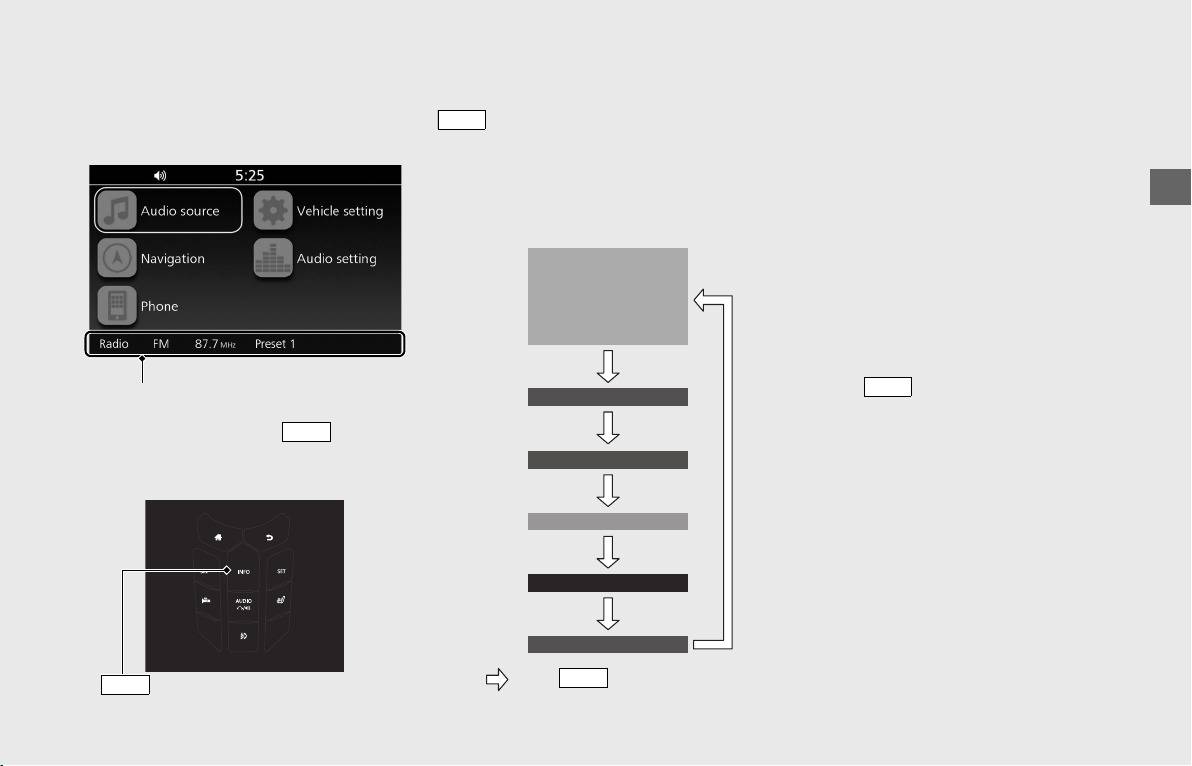
Home Screen
From this screen, you can go to various
functions and setup options.
When the ignition switch is turned ON or
ACC, you will see the screen you used last.
To return to the Home screen:
(P24)
❙
Clock (12-hour display)
To set the clock: (P78)
❙
Audio Source
Enters the current audio mode. (P71)
❙
Vehicle Setting
Enters the vehicle setting menu screen.
(P28)
❙
Navigation
Displays the navigation screen. (Refer to the
Navigation System manual.)
❙
Audio Setting
Enters the audio setting menu screen.
(P73)
❙
Phone
Enters the phone screen. (P104)
❙
Apple CarPlay
™
Appears the menu icon when Apple
CarPlay is available.
(P101)
To select a desired setting menu:
(P24)
switch
ENT
Interface dial ( )
ENTER
Clock
Operation Guide
24
Basic Operations
You can operate and set the various
functions of your vehicle using the interface
dial and buttons on the center panel and/or
switches on the left handlebar. However,
you cannot operate some functions by the
center panel switches/Interface dial while
the vehicle is in motion.
❙
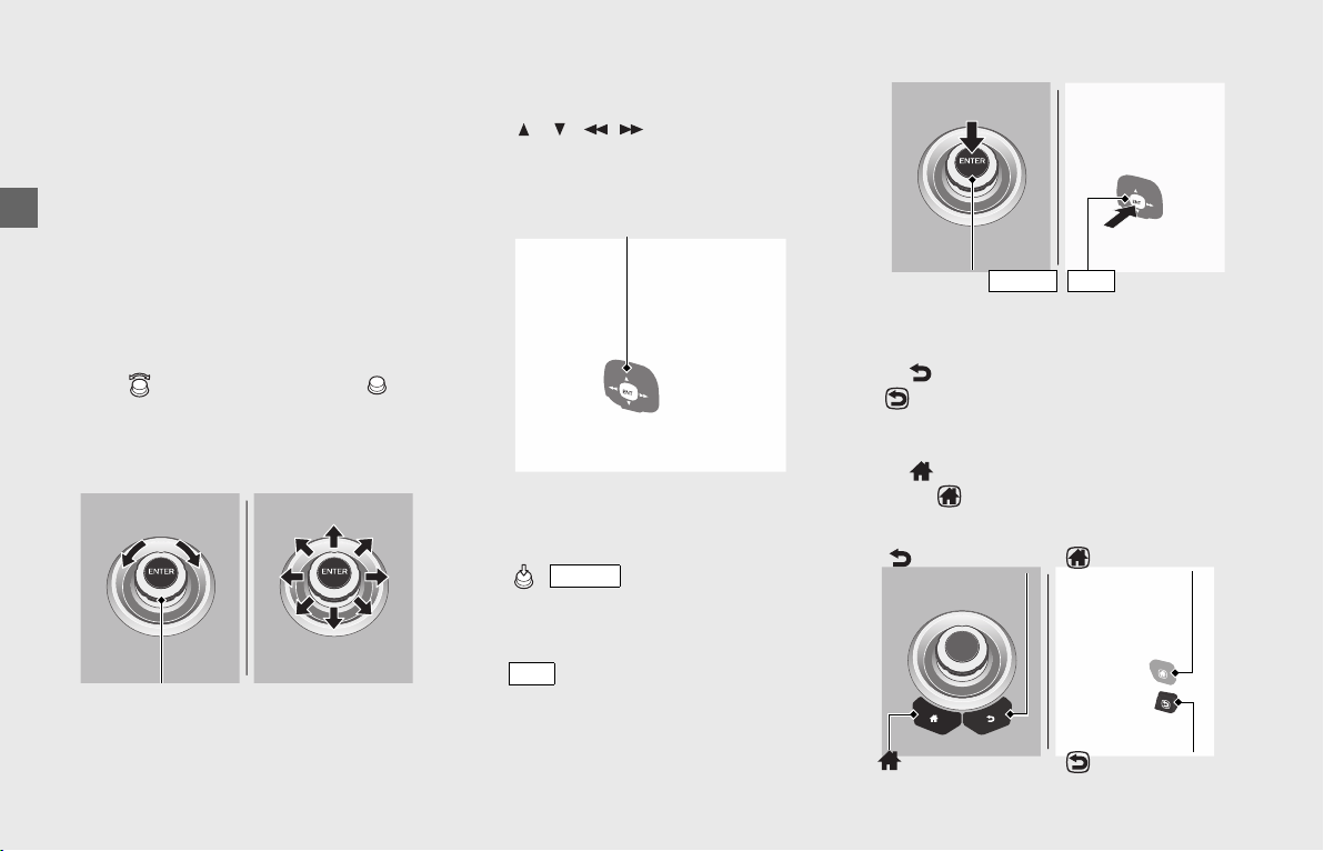
To Select a Desired Setting Menu
To operate with the interface dial on the
center panel:
Rotate (Interface dial) or move in
the eight possible directions to select the
available choices.
To operate with the 4-way key switch on
the left handlebar:
Press / / / to select the
available choices. Some menus will only use
the up and down function.
❙
To Set Your Selection
To operate with the interface dial on the
center panel:
Press (
)) to set your selection.
To operate with the 4-way key switch on
the left handlebar:
Press switch located at the center of
the 4-way key switch to set your selection.
❙
To End the Setting Menu
To return the previous screen:
Press (Back) button on the center panel
or (Back) switch on the left handlebar.
To return to the Home screen:
Press (Home) button on the center
panel or (Home) switch on the left
handlebar.
Interface dial
4-way key switch
ENTER
ENT
Interface dial ( )
ENTER
switch
ENT
(Home) switch
(Back) button
(Back) switch
(Home) button
Instruments (Continued)
Operation Guide
25
continued
Information Bar
Displays various information (current audio
source info., vehicle info., help info., or
system info.) on the information bar.
Normally, when you press button,
the current audio source information or
vehicle information is displayed.
To change the current audio source
information or vehicle information, press
button until the desired information
is displayed.
The information bar cycles through the
information as follows:
In the following cases, the information bar
will appear or change from the current
indication.
• Helpful information
(P27):
When your vehicle has helpful
information to notify you of.
• System information (P27):
When your vehicle has system
information to notify you of.
When your vehicle has information to
notify you of, only the highest priority
information is displayed.
Once you close an interrupt information by
pressing button, it will not be
displayed again until the ignition switch is
turned ON again.
Information bar
INFO
button
INFO
INFO
No indication
Press
button.
INFO
Current audio
source information
Trip A fuel
consumption
Trip B fuel
consumption
Current
Fuel Mileage
Elapsed Time
INFO
Operation Guide
26
Instruments (Continued)
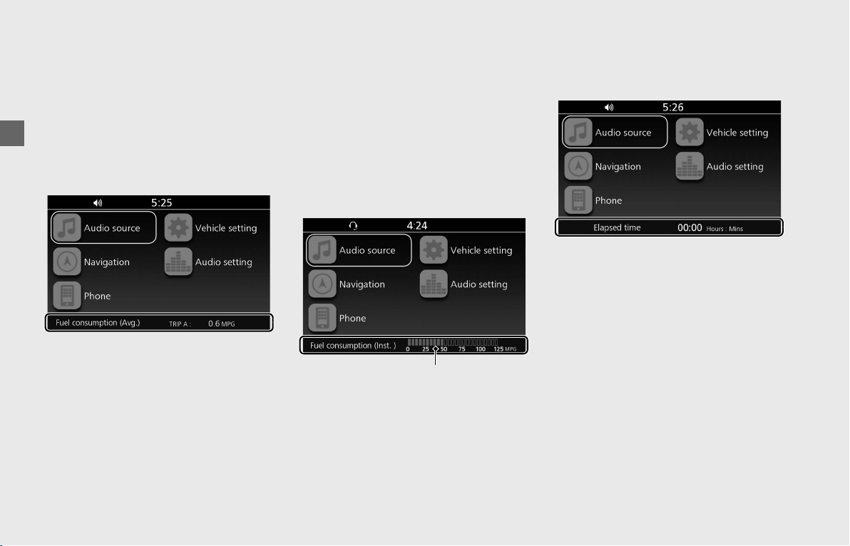
❙
Vehicle Information
Average Fuel Mileage (Trip A/Trip B)
[Fuel Consumption (Avg.)]
Displays the average fuel mileage since the
individual tripmeter was reset.
The average fuel mileage will be calculated
based on the mileage of the individual
tripmeter.
Display range:
0.1 to 99.9 MPG (L/100 km or
km/L)
•
If less than 0.1 MPG (L/100 km or km/L) or
more than 99.9 MPG (L/100 km or km/L):
“--.-” is displayed.
•
When tripmeter A or B is reset: “--.-” is
displayed.
When “--.-” is displayed except for the
above-mentioned cases, go to your dealer
for service.
To change the unit:
(P30)
To reset the average fuel mileage:
(P36)
Current Fuel Mileage [Fuel Consumption
(Inst.)]
Displays the instantaneous fuel mileage as
a bar graph in
MPG
,
L/100 km or km/L
.
• When your speed is less than 2 mph
(3 km/h): The bar graph is not activated.
When the bar graph is not activated except
for the above-mentioned cases, go to your
dealer for service.
To change the unit:
(P30)
Elapsed Time
Displays operating time since the engine
was started. (hours : minutes)
• Above 99:59: returns to 00:00.
When the ignition switch is turned OFF, the
elapsed time is reset.
Bar graph
Operation Guide
27
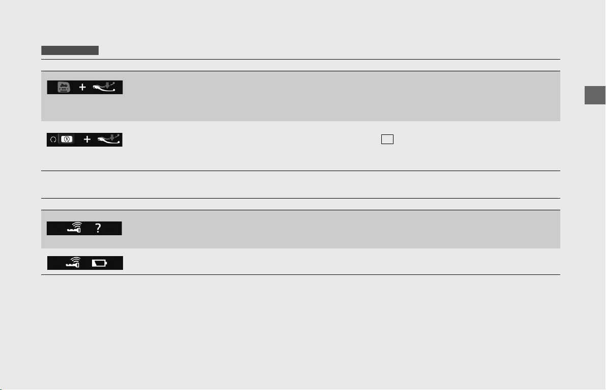
❙
Helpful Information
❙
System Information
Indication Explanation Remedy
Appears when pressing the Walking Speed mode
switch without applying the brake.
Before pressing the Walking Speed mode, apply the
brake.
For more information, refer to “Walking Speed
mode.”
(P117)
Appears when pressing the start button without
applying the brake while the transmission is in gear.
Before pressing the start button, put the gear to
Neutral ( indicator comes on) or Apply the brake.
For more information, refer to “Starting the Engine.”
(P112)
Indication Explanation Remedy
Appears when communication between your vehicle
and Honda SMART Key is interrupted after turning on
the electrical system.
Refer to “When the Honda SMART Key System Does
Not Operate Properly.”
(P188)
Appears when the battery of Honda SMART Key is
weak.
Refer to “Replacing the Honda SMART Key Battery.”
(P174)
GL1800BD/D/DA
N
Operation Guide
28
Instruments (Continued)
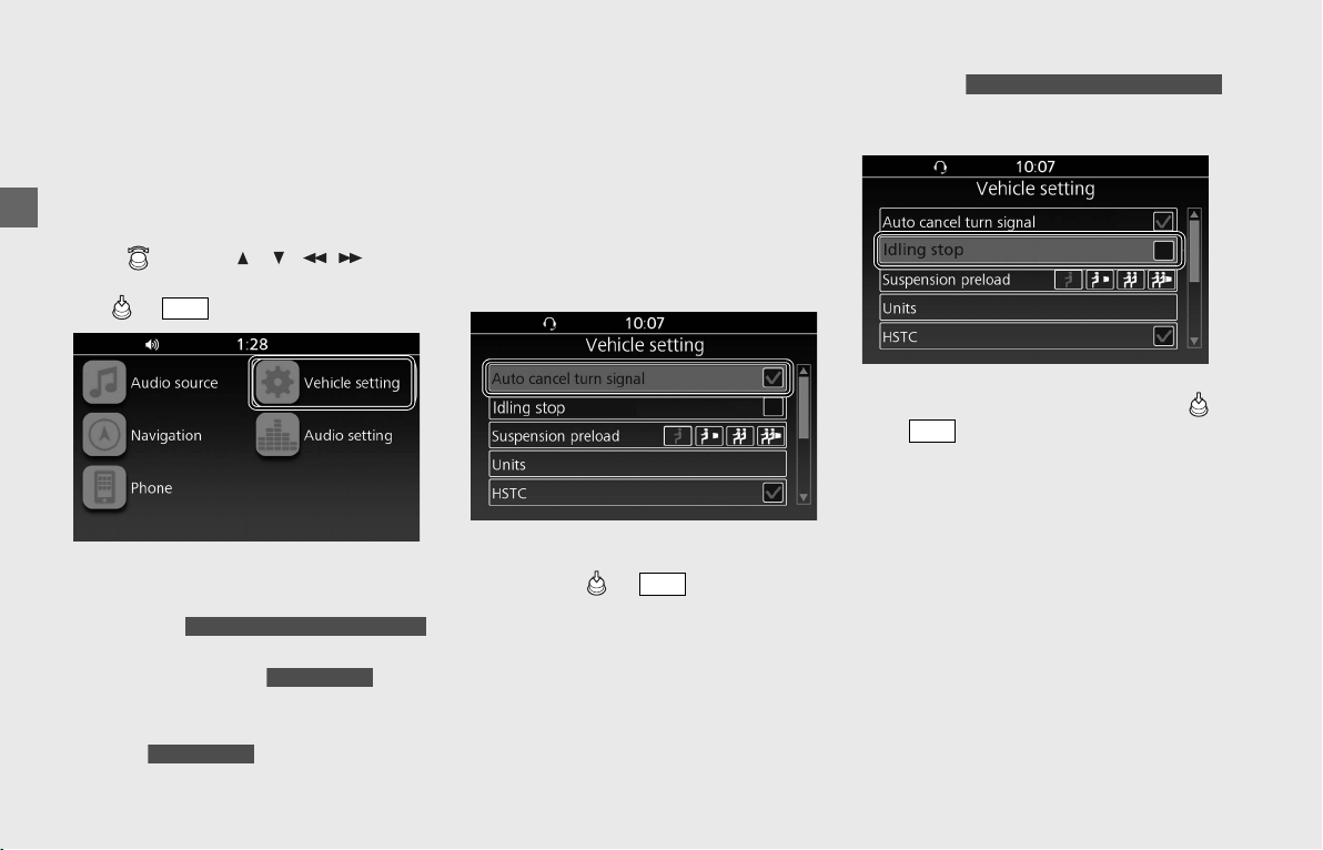
Vehicle Setting
You can configure the vehicle settings.
The vehicle settings are enabled with the
ignition switch in ON.
The vehicle settings are disabled while the
vehicle is in motion.
Rotate or press / / / on the
4-way key switch to select a setting menu.
Press or
switch to set your selection.
The vehicle settings contain the following:
•[Auto cancel turn signal]
(P28)
• [Idling stop]
(P28)
• [Suspension preload]
(P29)
•[Units] (P30)
• [HSTC] (P31)
•
[Auto Dimmer Meter Illumination]
(P32)
•[Day / Night] (P32)
•[Ext. Amp] (P33)
• [EQ1/EQ2] (Equalizer) (P33)
• [Head light opening] (P33)
❙
Auto Cancel Turn Signal
You can enable/disable turn signal
automatic cancellation.
!aSelect [Auto cancel turn signal], and
then press or switch to select
(enable) or deselect (disable) the
function.
!bReturn to the previous screen or the
Home screen.
(P24)
Default: On (selected)
❙
Idling Stop
You can enable/disable the Idling Stop
system.
!aSelect [Idling stop], and then press
or switch to change to select
(enable) or deselect (disable) the
function.
!bReturn to the previous screen or the
Home screen.
(P24)
Default: Off (deselected)
ENT
GL1800BD/D/DA Canada model only
GL1800/D/DA
GL1800/D/DA
ENT
GL1800BD/D/DA Canada model only
ENT
Operation Guide
29
continued
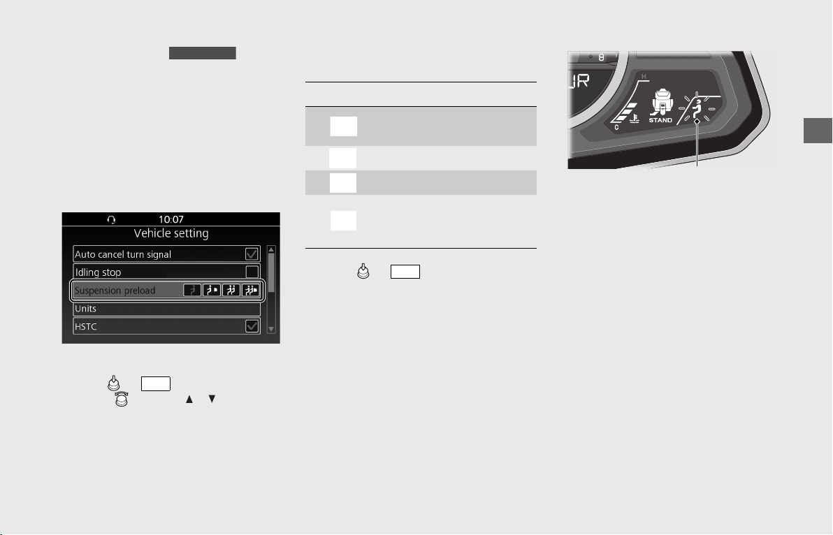
❙
Suspension Preload
You can automatically adjust the rear
suspension spring preload according to the
riding conditions by selecting from the four
pre-programmed settings.
The rear suspension spring preload
adjustment can be changed only when
your vehicle is stopped.
!a Select [Suspension preload], and then
press or switch.
!b Rotate or press / on the 4-
way key switch to select the setting
according to the riding conditions.
The rear suspension adjustment provides
the following settings.
!c Press or switch to set your
selection.
uThe selected status icon on the INFO 3
display flashes while transitioning
between setting modes.
The status icon comes on when the
suspension adjustment is completed.
!dReturn to the previous screen or the
Home screen.
(P24)
Electrical Adjustable Suspension:
(P172)
GL1800/D/DA
ENT
Status icon Riding condition
Rider only
(Minimum preload)
Rider and luggage
Rider and passenger
Rider, passenger and
luggage
(Maximum preload)
ENT
Status icon
Operation Guide
30
Instruments (Continued)
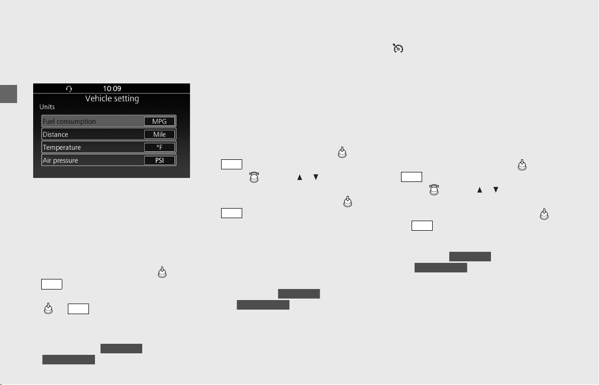
❙
Units
You can change the units used for fuel
consumption, distance, temperature and
air pressure.
To Change the Unit for Fuel Consumption
[Fuel consumption]
If you want to select “L/100 km” or “km/L”
for fuel consumption, “km” must be
selected in the [Distance] menu in advance.
When “Mile” for distance is selected, only
“MPG” can be selected.
!a Select [Units], and then press or
switch.
!b With [Fuel consumption] selected, pres
or switch until the desired
unit is displayed.
Selectable units:
L/100 km, km/L or MPG
Default: MPG ( ) / L/100 km
()
!cReturn to the previous screen or the
Home screen.
(P24)
The units for average fuel mileage [Fuel
consumption (Avg.)] and current fuel
mileage [Fuel consumption (Inst.)] are
changed in the information bar.
To Change the Unit for Distance
[Distance]
!aSelect [Units], and then press or
switch.
!b
Rotate or press / on the 4-way
key switch to select [
Distance
].
!cWith [Distance] selected, press or
switch to select the unit.
uIn conjunction with the change of the
unit for distance, the unit for fuel
consumption switches to “L/100 km
or km/L” or “MPG” automatically.
Selectable unit: km or Mile
Default: Mile ( ) /
km ( )
!dReturn to the previous screen or the
Home screen.
(P24)
The units for the cruise control set speed
( ), odometer [TOTAL], tripmeter A/B
[TRIP A/B] and available driving distance
[RANGE] are changed in the INFO 1 display.
In addition, the units for average fuel
mileage [Fuel consumption (Avg.)] and
current fuel mileage [Fuel consumption
(Inst.)] are changed in the information bar.
To Change the Unit for Air Temperature
Gauge [Temperature]
!aSelect [Units], and then press or
switch.
!b
Rotate or press / on the 4-way
key switch to select [Temperature].
!cWith [Temperature] selected, press
or switch to select the unit.
Selectable unit: °F or °C
Default: °F ( ) /
°C ( )
!dReturn to the previous screen or the
Home screen.
(P24)
The unit for air temperature gauge [AIR] is
changed in the INFO 1 display.
ENT
ENT
USA model
Canada model
ENT
ENT
USA model
Canada model
ENT
ENT
USA model
Canada model
Operation Guide
31
continued
To Change the Unit for Tire Pressure
Gauge [Air pressure]
!a Select [Units], and then press or
switch.
!b
Rotate or press / on the 4-way
key switch to select [Air pressure].
!c With [Air pressure] selected, press
or switch to select the unit.
Selectable unit: PSI or kPa
Default: PSI ( ) /
kPa ( )
!d Return to the previous screen or the
Home screen.
(P24)
The unit for air pressure gauge [Air Pressure]
is changed in the INFO 1 display.
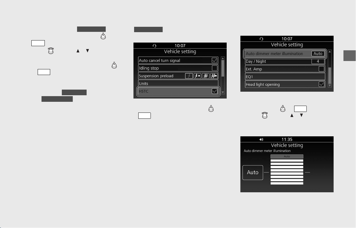
❙
HSTC (Honda Selectable Torque Control)
You can enable/disable the HSTC function.
!a Select [HSTC], and then press or
switch to select (enable) or
deselect (disable) the function.
!b Return to the previous screen or the
Home screen. (P24)
Default: On (selected)
Honda Selectable Torque Control
(Torque Control): (P122)
❙
Auto Dimmer Meter Illumination
You can select the backlight brightness.
!a
Select [Auto dimmer meter illumination],
and then press or
switch.
!b
Rotate or press / on the 4-way
key switch to select [AUTO] (Auto
adjustment) or your preferred level.
GL1800/D/DA
ENT
ENT
USA model
Canada model
GL1800/D/DA
ENT
ENT

Operation Guide
32
Instruments (Continued)
!c Return to the previous screen or the
Home screen. (P24)
Setting range: Level 1 to 8 or [AUTO]
Default: [AUTO]
The display can become dark when the
display is very hot. If it does not restore the
original brightness, contact your dealer.
Automatic Brightness Control:
(P214)
❙
Day / Night
You can adjust the settings for daytime
mode and nighttime mode of the
navigation map or applications such as
Maps (Apple CarPlay).
Changing of Setting Value
When the setting of [Auto dimmer meter
illumination] is [Auto]:
If you set to a higher value, the screen will
switch to nighttime mode at brighter
ambient lighting conditions.
If you set to a lower value, the screen will
switch to nighttime mode at darker
ambient lighting conditions.
When the setting of [Auto dimmer meter
illumination] is not [Auto]:
When the setting value of [Day / Night] is
higher than the setting value of [Auto
dimmer meter illumination], the screen will
switch to nighttime mode.
For example, when the setting value of
[Auto dimmer meter illumination] is 5, the
screen will switch to nighttime mode if [Day
/ Night] is set to 6 or higher.
Auto Dimmer Meter Illumination:
(P31)
Holding the Mode
When [Hold day mode] is selected, the
screen is always displayed in daytime mode.
When [Hold night mode] is selected, the
screen is always displayed in nighttime
mode.
!aSelect [Day / Night], and then press
or switch.
!b
Rotate or press / on the 4-way
key switch to select [Hold day mode],
[Hold night mode] or your preferred level.
!cReturn to the previous screen or the
Home screen.
(P24)
Default: Level 4
ENT
Operation Guide
33
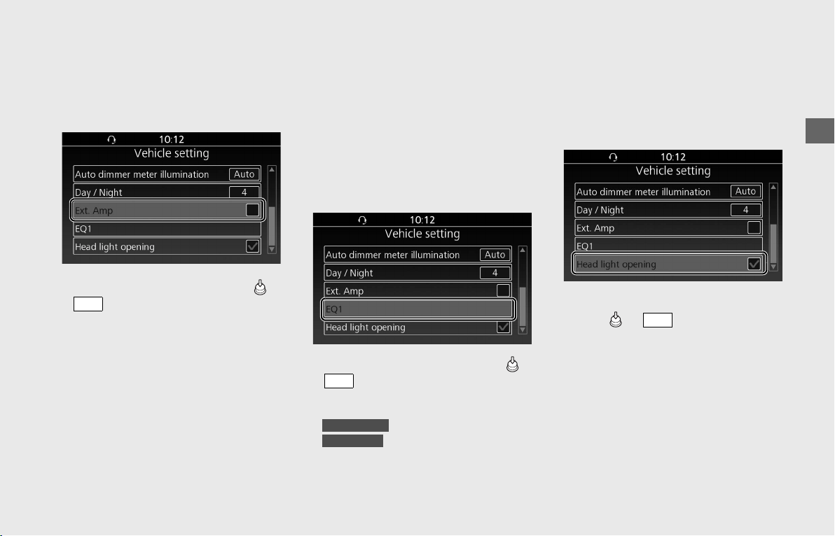
❙
Ext. Amp
You can enable/disable audio output when
an external amplifier is connected.
If you want to install an external amplifier,
contact your dealer.
!a Select [Ext. Amp], and then press or
switch to select (enable) or
deselect (disable) the function.
!b Return to the previous screen or the
Home screen.
(P24)
Default: Off (deselected)
❙
EQ1/EQ2 (Equalizer)
You can select from two equalizer curves
according to the specifications of your vehicle.
• [EQ 1] is an equalizer curve suitable for
the front speakers and rear speakers
mounted on the travel trunk.
• [EQ 2] is an equalizer curve suitable for
the front speakers only or the front
speakers and optional rear speakers
mounted on the saddlebags.
!a
Select [EQ1] or [EQ2], and then press or
switch to change the equalizer curve.
Default:
: [EQ1]
: [EQ2]
!b Return to the previous screen or the
Home screen.
(P24)
❙
Head Light Opening
You can enable/disable the headlight
startup lighting when the ignition switch is
turned ON.
When the setting is enabled, the headlight
gradually lights up.
!aSelect [Headlight opening], and then
press or switch to select
(enable) or deselect (disable) the
function.
!bReturn to the previous screen or the
Home screen.
(P24)
Default: On (selected)
ENT
ENT
GL1800/D/DA
GL1800B/BD
ENT
Operation Guide
34
Instruments (Continued)
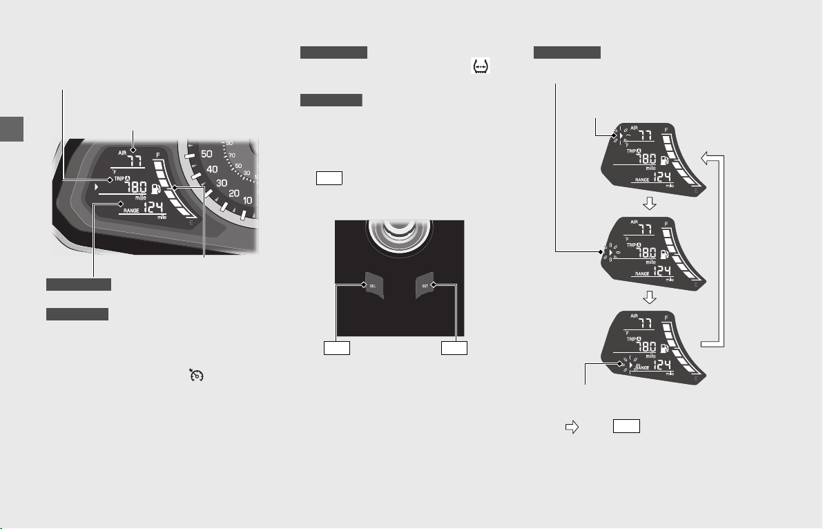
INFO 1 Display
INFO 1 display contains the following:
• Cruise control set speed ( ) and Air
temperature gauge [AIR] display (P35)
• Odometer [TOTAL] & Tripmeter [TRIP A/
TRIP B] display (P36)
• Available driving distance
[RANGE] & Tire pressure gauge [ FR/
RR] display
(P37)
Available driving distance
[RANGE] display (P37)
• Fuel gauge (P38)
Changing the INFO 1 Display
Press button to move the cursor to a
desired display.
Cruise control set speed &
Air temperature gauge display
Odometer & Tripmeter display
Available driving distance
& Tire pressure gauge display
Available driving distance
display
GL1800/D/DA
GL1800B/BD
Fuel gauge
GL1800/D/DA
GL1800B/BD
SEL
button
SEL
button
SET
GL1800/D/DA
Odometer & Tripmeter display
Cruise control set speed &
Air temperature gauge display
Available driving distance &
Tire pressure gauge display
Press button.
SEL
Operation Guide
35
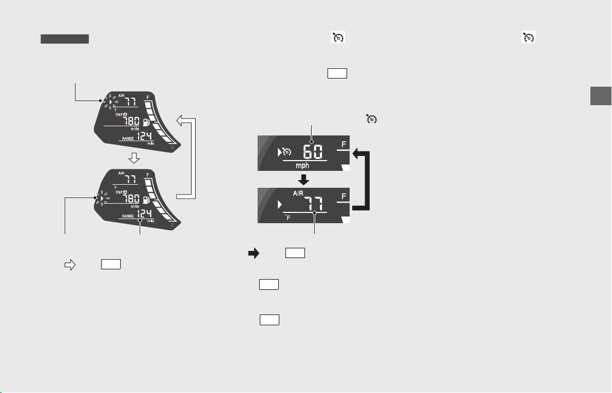
❙
Cruise Control Set Speed ( ) & Air
temperature Gauge [AIR] Display
To select cruise control set speed or Air
temperature gauge, Press button
when the cursor is at cruise control set
speed and Air temperature gauge display.
!a Press button to move the cursor to
the cruise control set speed and air
temperature gauge display.
!b Press button to select the cruise
control set speed or air temperature
gauge.
Cruise Control Set Speed ( )
The speed set for the cruise control is
displayed.
If the cruise control set speed does not
memorized, “---” is displayed.
Cruise Control:
(P123)
Air Temperature Gauge [AIR]
Displays ambient temperature.
Display range: 14 to 122°F (−10 to 50°C)
• Below 13°F (−11°C): “---” is displayed
• Above 122°F (50°C): 122°F or 50°C
flashes
The temperature readout may be incorrect
at low speeds due to reflected heat.
GL1800B/BD
Odometer &
Tripmeter display
Cruise control set speed &
Air temperature gauge display
Press button.
SEL
Available driving
distance display
SET
Cruise control set speed ( )
Air temperature gauge
Press button.
SET
SEL
SET
Operation Guide
36
Instruments (Continued)
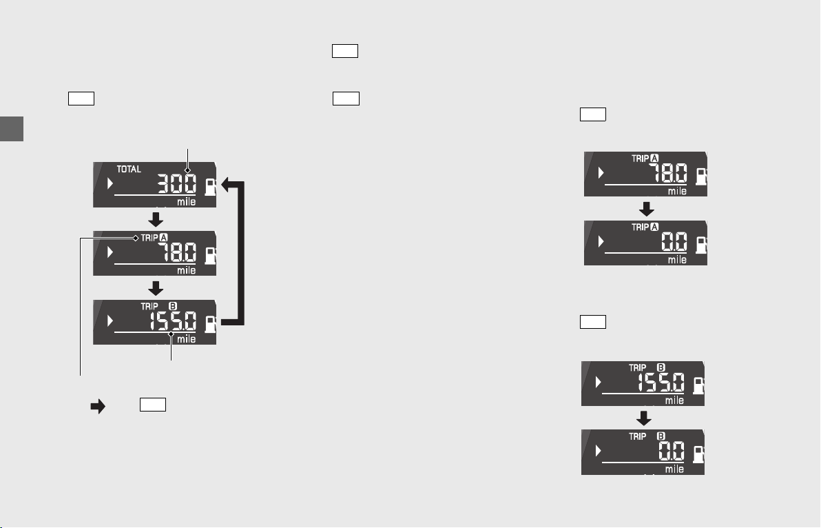
❙
Odometer [TOTAL] & Tripmeter [TRIP A/B]
Display
To select Odometer or Tripmeter A or B,
Press button when the cursor is at the
Odometer and Tripmeter display.
!aPress button to move the cursor to
the odometer, tripmeter A and
tripmeter B display.
!bPress button to select the
odometer, tripmeter A or tripmeter B.
Odometer [TOTAL]
Total distance ridden.
When “------” is displayed, go to your
dealer for service.
Tripmeter A/B [TRIP A/B]
Distance ridden since the tripmeter was
reset.
When “----.-” is displayed, go to your
dealer for service.
To reset the tripmeter:
(P36)
❙
To Reset the Tripmeter and Average
Fuel Mileage
To reset tripmeter A and average fuel
mileage (based on tripmeter A), press and
hold the button while tripmeter A is
displayed.
To reset tripmeter B and average fuel
mileage (based on tripmeter B), press and
hold the button while tripmeter B is
displayed.
SET
Odometer [TOTAL]
Tripmeter [TRIP A]
Tripmeter [TRIP B]
Press button.
SET
SEL
SET
SET
SET
Operation Guide
37
❙
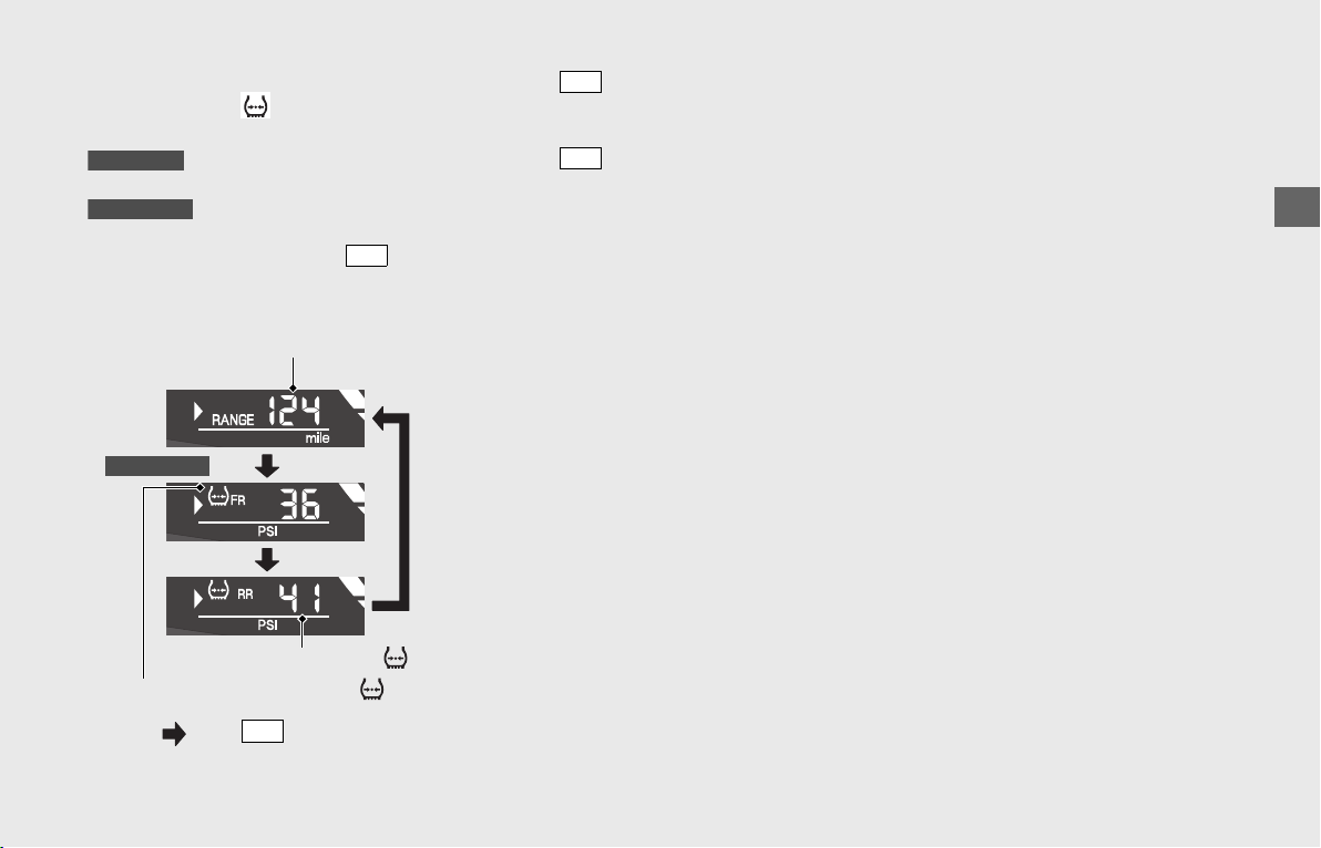
Available Driving Distance [RANGE] & Tire
Pressure Gauge [
FR/RR] Display
Available driving distance is only displayed.
To select Available driving distance, Tire
pressure gauge FR or RR, press button
when the cursor is at the Available driving
distance and Tire pressure gauge display.
!a Press button to move the cursor to
the available driving distance and tire
pressure gauge display.
!b Press button to select the available
driving distance, front tire pressure
gauge or rear tire pressure gauge.
Available Driving Distance [RANGE]
Displays the estimated distance you can
travel on the remaining fuel.
The indicated available driving distance is
calculated based on the driving conditions,
and the indicated figure may not always be
the actual available distance.
• Initial display (factory shipped): “---” is
displayed until riding for 4 minutes at 2
mph (3 km/h) or more.
• After the second time, when the amount
of remaining fuel does not change, the
last driving distance is displayed. When
the amount of remaining fuel is
changed, recalculate and update the
available driving distance.
•
When the calculated distance is below
3 mile (5 km) or the amount of
remaining fuel is below 0.26 US gal
(1.0 liters):
“---” is displayed.
When “---” is displayed except for the
above-mentioned cases, go to your dealer
for service.
GL1800B/BD
GL1800/D/DA
SET
Available driving distance [RANGE]
Front tire pressure gauge [ FR]
Rear tire pressure gauge [ RR]
Press button.
SET
GL1800/D/DA
SEL
SET

Operation Guide
38
Instruments (Continued)
Tire Pressure Gauge [ FR/RR]
Displays tire pressure for the selected tire.
The system does not monitor the tire
pressure at speed below about 16 mph
(25 km/h). “---” is displayed until the
specified speed is reached.
Display range: 0 to 59 PSI (0 to 405 kPa)
Always use the recommended front/rear
tires to ensure correct the tire pressure
reading.
The indicated tire pressures may fluctuate
when riding because the tire pressure varies
according to the temperature.
The tire pressure shown on the display may
be slightly different from the actual tire
pressure as measured by a tire gauge.
If there is a significant difference between
the two values, or if the low tire pressure
indicator and TPMS indicator do not go off
after you have inflated the tire to the
specified pressure, have the system
checked by a dealer.
When “---” is displayed except for the
above-mentioned cases, go to your dealer
for service.
❙
Fuel Gauge
Remaining fuel when only 1st (E) segment
starts flashing: approximately 0.92 US gal
(3.5 liters)
At the same time, the low fuel indicator
comes on.
(P44)
If the fuel gauge flashes in a repeat
pattern or turns off:
(P183)
GL1800/D/DA
1st (E) segment
Operation Guide
39
continued
INFO 2 Display
INFO 2 display contains the following:
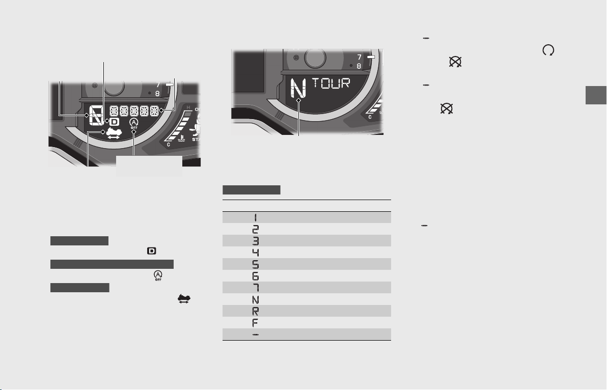
• Gear position indicator (P39)
• Riding mode indicator (P40)
•
D (AT MODE) indicator ( ) (P40)
•
Idling Stop OFF indicator ( )
(P40)
•
Walking Speed mode indicator ( )
(P40)
❙
Gear Position Indicator
The gear position is shown in the gear
position indicator as follows:
u“ ” flashes when the engine stop
switch position is changed from
(Run) to (Stop) position with the
ignition switch in ON.
u“ ” flashes when the ignition switch is
turned ON with the engine stop switch
in the (Stop) position.
The indicator may flash if:
uThe front wheel leaves the ground.
uYou turn the wheel while the vehicle is
upright on the stand.
This is normal. To operate the system again,
turn the ignition switch to OFF, and then to
ON again.
If “ ” is blinking in the gear position
indicator while riding:
(P185)
D (AT MODE) indicator
Gear position
indicator
Riding mode indicator
Idling Stop OFF
indicator
Walking Speed
mode indicator
GL1800BD/D/DA
GL1800BD/D/DA Canada model only
GL1800BD/D/DA
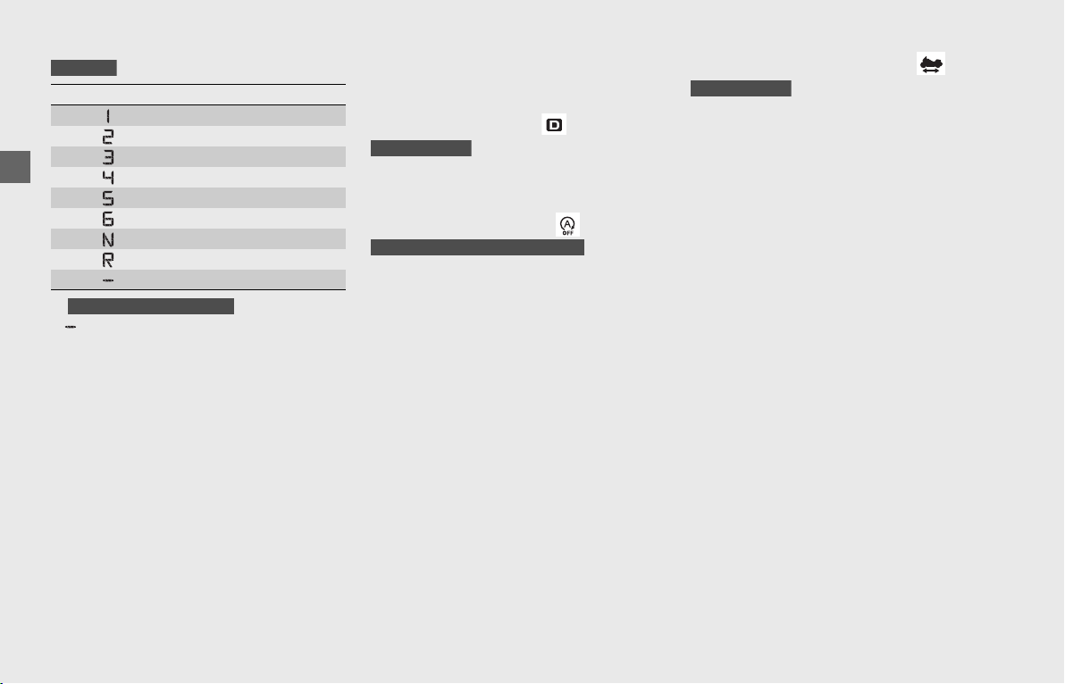
Indication Gear position
1st gear
2nd gear
3rd gear
4th gear
5th gear
6th gear
7th gear
Neutral
Reverse
Forward
Shifting failure
Gear position indicator
GL1800BD/D/DA
Operation Guide
40
Instruments (Continued)
*
“ ” flashes when the transmission is not
shifted properly.
❙
Riding Mode Indicator
Refer to "Riding Mode" (P120)
❙
D (AT MODE) Indicator (
)
Comes on when AT MODE is selected.
(P116)
❙
Idling Stop OFF Indicator (
)
Comes on briefly when the ignition switch
is turned ON.
Comes on when the Idling Stop system is
off.
Idling Stop system:
(P61)
❙
Walking Speed Mode Indicator ( )
Comes on when in Walking Speed mode.
Walking Speed Mode:
(P117)
Indication Gear position
1st gear
2nd gear
3rd gear
4th gear
5th gear
6th gear
Neutral
Reverse*
Shifting failure
GL1800/B
Except GL1800B USA model
GL1800BD/D/DA
GL1800BD/D/DA Canada model only
GL1800BD/D/DA
Operation Guide
41
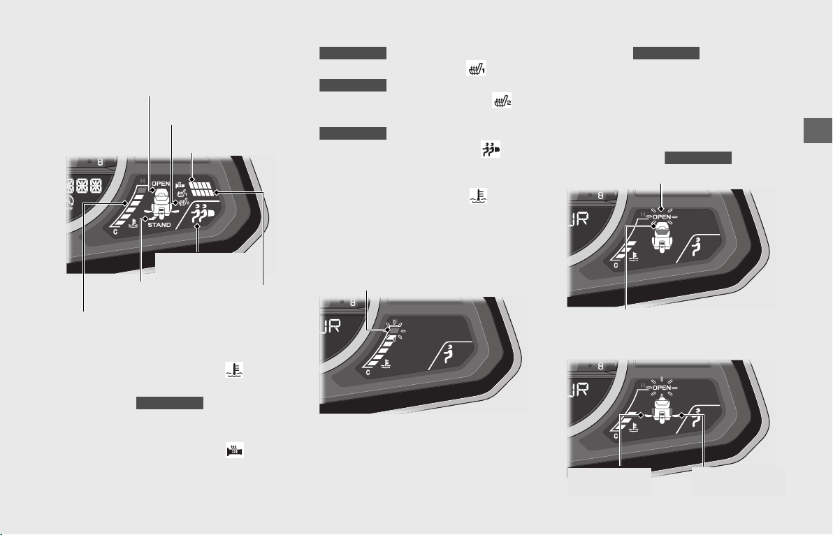
INFO 3 Display
INFO 3 display contains the following:
• Coolant temperature gauge
()
(P41)
• Travel trunk & Saddlebags
open indicator
(P41)
• Side stand indicator (P42)
• Handle grip heater indicator
()
(P42)
•
Rider seat heater indicator
()
(P42)
•
Passenger seat heater indicator
()
(P43)
•
Suspension preload indicator
()
(P43)
❙
Coolant Temperature Gauge ( )
When the coolant is over the specified
temperature, the 6th (H) segment flashes
and the high coolant temperature indicator
comes on.
If the 6th (H) segment flashes while
riding:
(P178)
If the all segments flashes: (P184)
❙
Travel Trunk & Saddlebags
Open Indicator
The segment(s) of open component(s)
flashes with the "OPEN" indicator when
your vehicle’s travel trunk and/or
saddlebags are open.
Travel trunk open
Saddlebag open
Coolant temperature gauge
Travel trunk & Saddlebags
open indicator
Side stand
indicator
Handle grip heater
indicator
Rider seat heater
indicator
Passenger seat heater
indicator
Suspension
preload indicator
GL1800/D/DA
GL1800/D/DA
GL1800/D/DA
GL1800/D/DA
6th (H) segment
GL1800/D/DA
GL1800/D/DA
“OPEN” indicator
Trunk segment
Left saddlebag
segment
Right saddlebag
segment
Operation Guide
42
Instruments (Continued)
❙
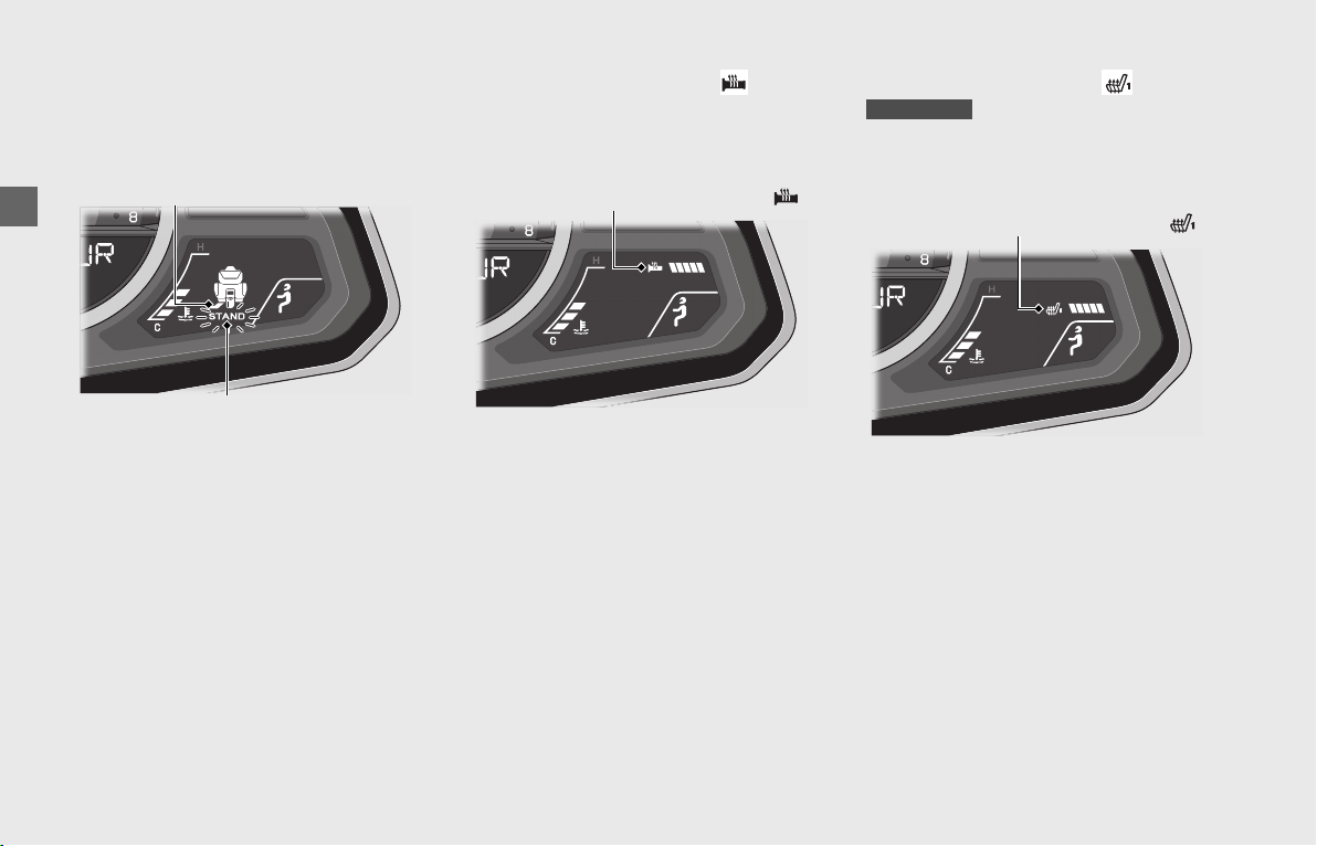
Side Stand Indicator
The side stand segment flashes with the
"STAND" when the side stand is put down.
It goes off when the side stand is raised.
❙
Handle Grip Heater Indicator ( )
Comes on when the handle grip heater is
on and indicates the selected heater level.
The handle grip heater has 5 levels.
When the handle grip heater indicator
flashes, go to your dealer for service.
To operate the handle grip heater:
(P133)
If the handle grip heater indicator
blinks: (P183)
❙
Rider Seat Heater Indicator ( )
Comes on when the rider seat heater is on
and indicates the selected heater level.
The rider seat heater has 5 levels.
When the rider seat heater indicator
flashes, go to your dealer for service.
To operate the rider seat heater:
(P134)
If the rider seat heater indicator blinks:
(P184)
Side stand segment
“STAND” indicator
Handle grip heater indicator ( )
GL1800/D/DA
Rider seat heater indicator ( )
Operation Guide
43
❙
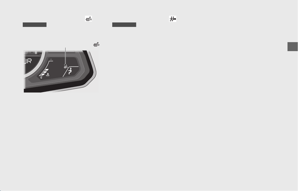
Passenger Seat Heater Indicator ( )
Comes on when the passenger seat heater
is on.
When the passenger seat heater indicator
flashes, go to your dealer for service.
To operate the passenger seat heater:
(P135)
If the passenger seat heater indicator
blinks: (P184)
❙
Suspension Preload Indicator ( )
Shows selected rear suspension spring
preload.
The indicator flashes while transitioning
between setting modes.
When the indicator flashes except for the
above mentioned cases, go to your dealer
for service.
Electrical Adjustable Suspension:
(P172)
GL1800/D/DA
Passenger seat heater indicator ( )
GL1800/D/DA
Operation Guide
44
Indicators
Low fuel indicator
• Comes on briefly when the ignition switch is turned ON.
• Comes on when there is only reserve fuel left in the fuel tank. Remaining fuel
when low fuel indicator comes on: 0.92 US gal (3.5 liters)
If the indicator comes on:
(P127)
Left turn signal indicator
If one of these indicators does not come on when it should, have your dealer check for problems.
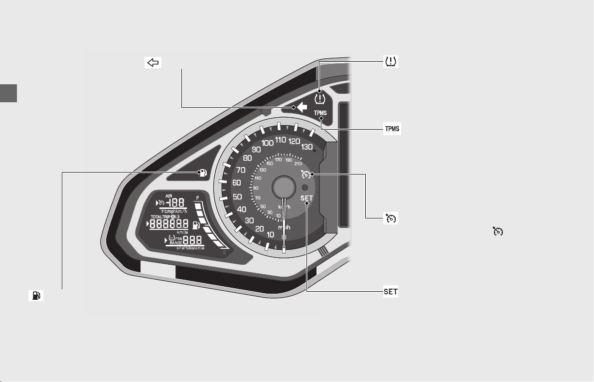
TPMS indicator
Comes on briefly when the ignition switch
is turned ON.
If the indicator comes on:
(P182)
CRUISE SET indicator
Comes on if you have set a speed for
cruise control.
Cruise Control:
(P123)
Low tire pressure indicator
Comes on briefly when the ignition
switch is turned ON.
If the indicator comes on or flashes:
(P181)
CRUISE MAIN indicator
Comes on when you press
(cruise control main) switch.
Cruise Control:
(P123)
Operation Guide
45
Comes on briefly when the ignition
switch is turned ON.
If the indicator comes on while
engine is running: (P179)
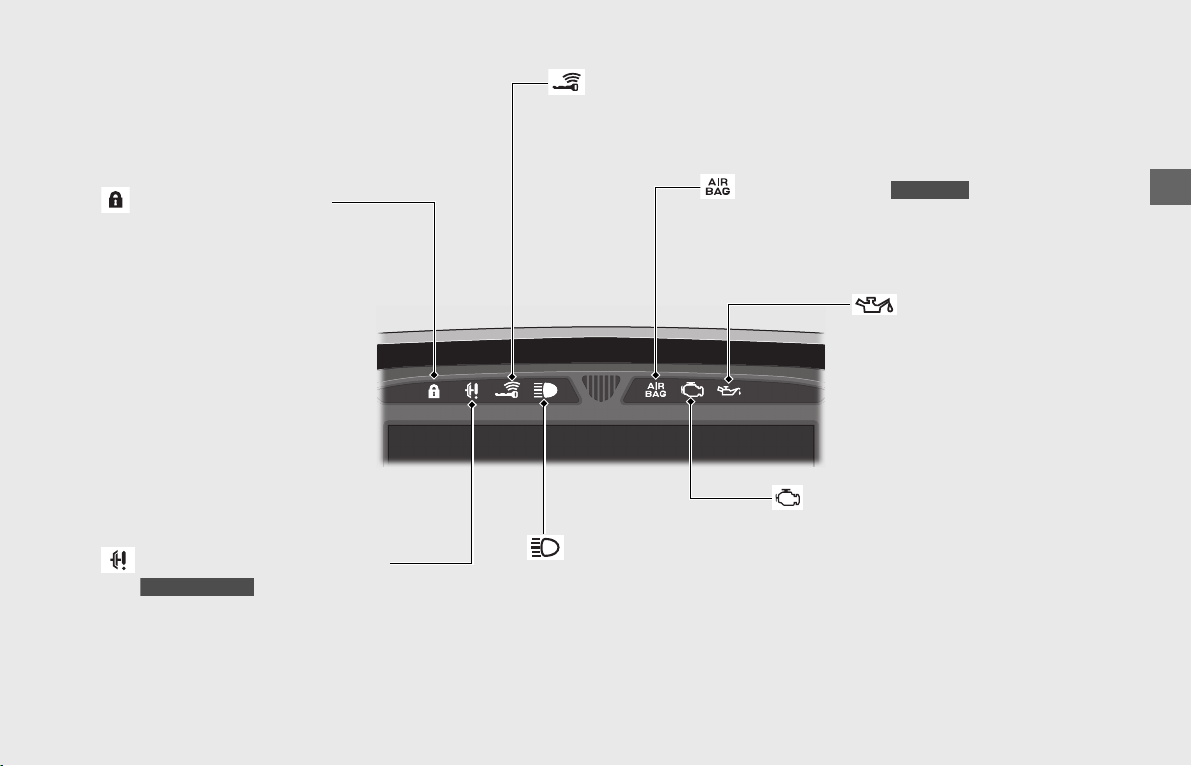
Steering lock indicator
Comes on briefly while the
steering lock is activating.
Steering lock:
(P55)
Clutch temperature indicator
Comes on briefly when the ignition
switch is turned ON.
If the indicator flashes on while
riding:
(P181)
GL1800BD/D/DA
Honda SMART Key indicator
Comes on briefly when the ignition switch is turned ON.
When the Honda SMART Key Indicator Flashes:
(P180)
High beam indicator
AIRBAG indicator
Comes on briefly when the ignition switch is turned
ON.
If the indicator comes on while riding:
(P182)
GL1800DA
PGM-FI (Programmed Fuel
Injection) malfunction indicator
lamp (MIL)
Low oil pressure indicator
Comes on when the ignition switch
is turned ON. Goes off when the
engine starts.
If the indicator comes on while
engine is running:
(P179)
Operation Guide
46
Indicators (Continued)
Torque Control indicator
• Comes on when the ignition switch is turned
ON. Goes off when your speed reaches
approximately 3 mph (5 km/h) to indicate
Torque Control is ready to work.
• Blinks when Torque Control is operating.
If the indicator comes on while riding:
(P180)
GL1800/D/DA
Torque Control OFF indicator
Comes on when Torque Control is turned
off.
GL1800/D/DA
Neutral indicator
Comes on when the transmission
is in Neutral.
Right turn signal indicator
Hill start assist (HSA) indicator
Comes on in white to amber when the ignition
switch is turned ON. Goes off when your speed
reaches approximately 3 mph (5 km/h).
Hill start assist: (P126)
If the indicator comes on in amber while
riding
: (P182)
Idling Stop indicator
Comes on briefly when the ignition
switch is turned ON.
Idling Stop system:
(P61)
GL1800BD/D/DA Canada model only
Operation Guide
47
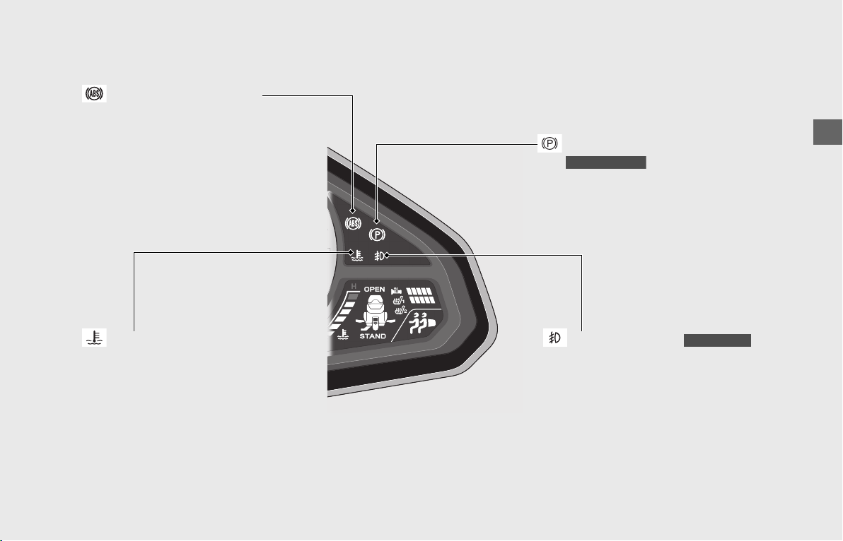
High coolant temperature indicator
Comes on briefly when the ignition switch
is turned ON.
If the indicator comes on while riding:
(P178)
Combined ABS indicator
Comes on when the ignition switch is
turned ON. Goes off when your speed
reaches approximately 3 mph (5 km/h).
If the indicator comes on while riding:
(P179)
Parking brake indicator
Comes on as a reminder that you have not
released the parking brake lever.
(P60)
GL1800BD/D/DA
Fog light indicator
Comes on when the fog lights are on.
GL1800/D/DA
Operation Guide
48
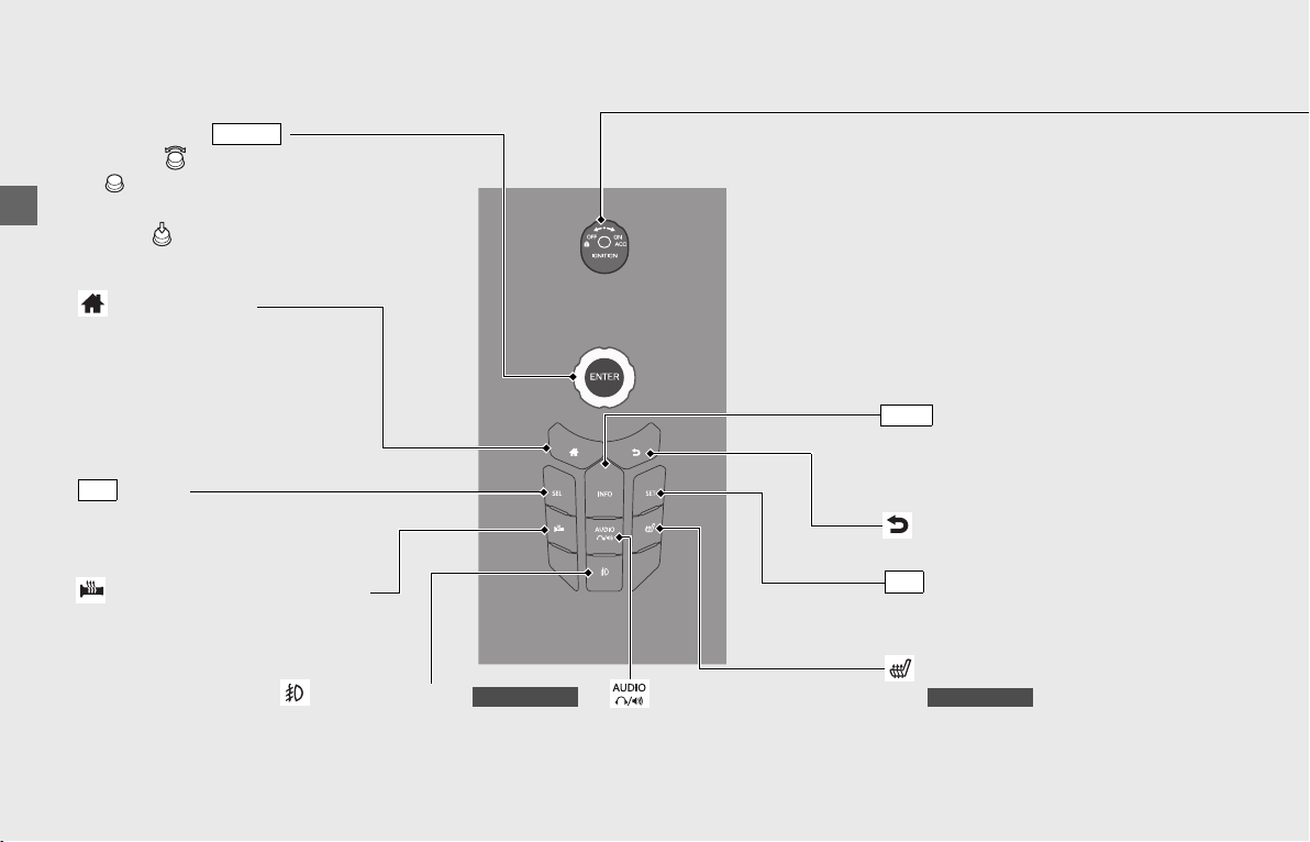
Switches
Center Panel
button
Press to move the cursor on the
INFO 1 display.
(P34)
SEL
Interface dial ( )
• Rotate (Interface dial) or move
in the eight possible directions to
select the available choices.
• Press (Enter) to set your selection.
Basic Operations:
(P24)
ENTER
(Home) button
Press to return to the Home
screen. (P24)
button
Press to switch the audio
output source. (P71)
(Handle grip heater) button
Press to adjust the handle grip
heater level.
(P133)
(Rider seat heater) button
Press to adjust the rider seat heater level.
(P134)
GL1800/D/DA
(Back) button
Press to return the previous screen.
(P24)
button
Press to display the information bar on
the multi-information display.
(P25)
INFO
button
Press to select the desired display
(P34)
or to reset the tripmeter. (P36)
SET
Fog light button
Press to turn the fog lights on or off.
GL1800/D/DA
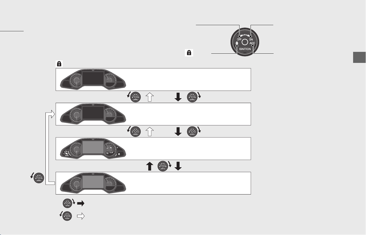
Operation Guide
49
Turns engine off.
Turns electrical system on for starting/riding.
Turns electrical system on for the audio system
and other accessories.
: Turning the ignition switch clockwise.
: Turning the ignition switch counterclockwise.
(Lock)
OFF
ON
ACC
Locks steering. (P55)
Ignition switch
Switches the electrical system on/off, locks the steering.
Make sure that the Honda SMART Key is activated
(P56)
and enter the operating range. (P57)
OFF ON
ACC
(Lock)
Operation Guide
50
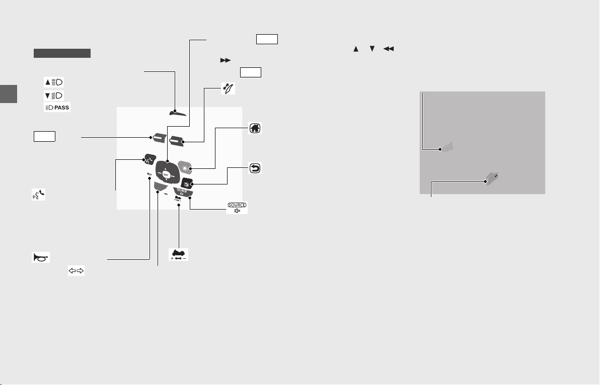
Switches (Continued)
Left handlebar
GL1800BD/D/DA
Headlight dimmer switch
• : High beam
• : Low beam
• : Flashes the high
beam headlight.
lever
Push up or down to
adjust the audio
system volume.
(P71)
VOL
4-way key/ switch
• Press the 4-way key switch in the / / /
directions to select the available choices.
•Press switch to set your selection.
(P24)
ENT
ENT
(Voice control) switch
• Press to receive, reject or
end a call.
(P104)
• Starts Siri
®
if Apple CarPlay
is available. (P103)
Horn button
Turn signal switch
• The turn signal will automatically stop when you complete the turn.
• When used for a lane change, the turn signal automatically stops after 7 seconds or after riding 131 yards (120 m).
u You can manually cancel the turn signal by pressing the switch in.
u In some cases, the timing at which the turn signal stops is changed.
u Always use the recommended tires to ensure correct automatic cancellation operation.
To enable or disable the turn signal automatic cancellation: (P28)
Shift up switch (+)
• Pull to shift up a gear.
(P116)
• Pull to move the vehicle forward
during the Walking Speed mode.
(P117)
Windscreen adjusting lever
Push up or down to adjust the
windscreen height.
(P136)
Walking Speed mode switch
Press to enter the Walking Speed mode.
(P117)
Shift down switch (-)
• Press to shift down a gear.
(P116)
• Press to move the vehicle backward
during the Walking Speed mode.
(P117)
(Home) switch
Press to return to the
Home screen.
(P24)
(Back) switch
Press to return to the
previous screen.
(P24)
(Source/Private Mode) switch
• Press to change the audio mode.
(P71)
• Press and hold to enable/disable the
private mode. (P90)
Operation Guide
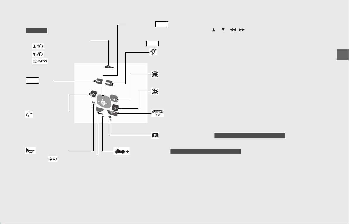
51
GL1800/B
Headlight dimmer switch
• : High beam
• : Low beam
• : Flashes the high
beam headlight.
lever
Push up or down to
adjust the audio
system volume.
(P71)
VOL
4-way key/ switch
• Press the 4-way key switch in the /// directions
to select the available choices.
•Press switch to set your selection.
(P24)
ENT
ENT
(Voice control) switch
• Press to receive, reject or
end a call.
(P104)
• Starts Siri if Apple CarPlay
is available. (P103)
Horn button
Turn signal switch
• The turn signal will automatically stop when you complete the turn.
• When used for a lane change, the turn signal automatically stops after 7 seconds or after riding 131 yards (120 m).
u You can manually cancel the turn signal by pressing the switch in.
u In some cases, the timing at which the turn signal stops is changed.
u Always use the recommended tires to ensure correct automatic cancellation operation.
To enable or disable the turn signal automatic cancellation: (P28)
(Source/Private Mode) switch
• Press to change the audio mode.
(P71)
• Press and hold to enable/disable the private mode. (P90)
Reverse mode switch
Press to enter the reverse mode.
(P119)
GL1800 and GL1800B Canada model
Reverse button
While pressing the switch, your vehicle will back up in the reverse mode.
(P119)
GL1800 and GL1800B Canada model
Windscreen adjusting lever
Push up or down to adjust the
windscreen height.
(P136)
(Home) switch
Press to return to the Home screen.
(P24)
(Back) switch
Press to return to the previous screen.
(P24)
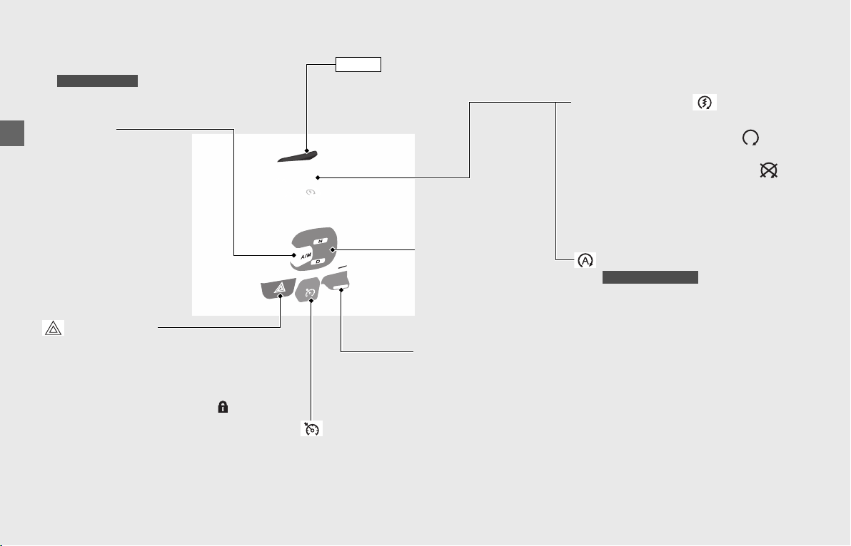
Operation Guide
52
Switches (Continued)
Engine stop switch/ Start
button
Should normally remain in the
(Run) position.
u In an emergency, switch to the
(Stop) position to stop the engine.
u Press the start button to start the
engine.
(P112)
Right handlebar
GL1800BD/D/DA
Hazard switch
Switchable when the ignition switch is
ON. Can be turned to off regardless
of the ignition switch position.
u The signals continue flashing with
the ignition switch in OFF or
(Lock) after the hazard switch is on.
A/M switch
Shifts between AT MODE
and MT MODE.
(P116)
N-D switch
To shift between Neutral
and AT MODE
. (P116)
Cruise control lever
Push up or down to set the
speed or adjust the set speed.
(P123)
button
Changes the riding mode.
(P120)
MODE
Cruise control main switch
Press to activate the cruise control system.
(P123)
Idling stop button
u Press to switch the Idling Stop
system on or off while engine is
running.
(P61)
Canada model only
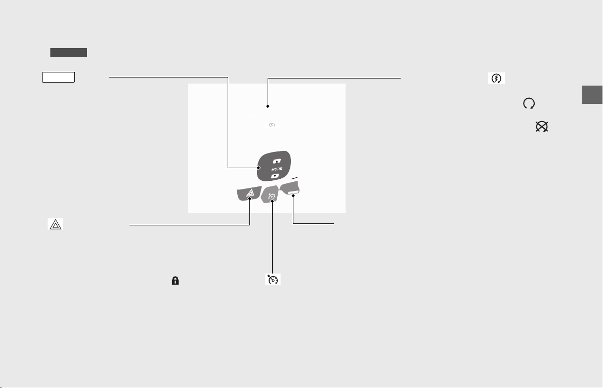
Operation Guide
53
GL1800/B
Hazard switch
Switchable when the ignition switch
is ON. Can be turned to off regardless
of the ignition switch position.
u The signals continue flashing with
the ignition switch in OFF or
(Lock) after the hazard switch is on.
Engine stop switch/ Start
button
Should normally remain in the
(Run) position.
u In an emergency, switch to the
(Stop) position to stop the engine.
u Press the start button to start the
engine.
(P112)
Cruise control lever
Push up or down to set the
speed or adjust the set speed.
(P123)
button
Changes the riding mode.
(P120)
MODE
Cruise control main switch
Press to activate the cruise control system. (P123)
Operation Guide
54
Switches (Continued)
ON/OFF button
This button is used to activate
or deactivate the Honda
SMART Key system and also to
confirm the activation status.
(P56)
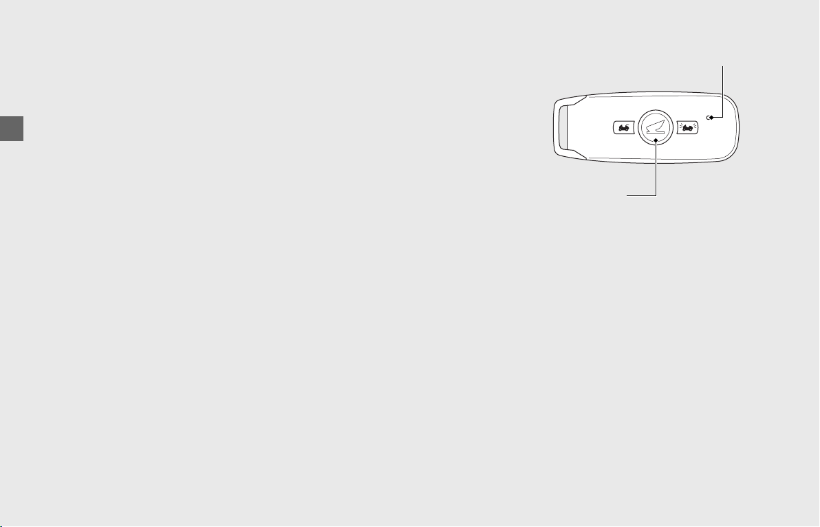
Honda SMART KeyPassenger seat
Answer back button
When pressing and holding the
button with the electrical system
off, your vehicle informs you of its
location by flashing the turn signal
lights and sounding the horn.
(P59)
UNLOCK button
Press this button to unlock the
travel trunk ( ),
saddlebags
(P128) and fairing
pocket. (P129)
GL1800/D/DA
LED
The LED informs you
of current status of
the Honda SMART
Key System.
(P56)
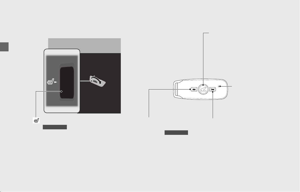
(Passenger seat heater) switch
Turn to adjust the passenger seat heater level.
(P135)
GL1800/D/DA
Operation Guide
55
Steering Lock
Lock the steering when parked to help
prevent theft.
A U-shaped wheel lock or similar device is
also recommended.
u When using a U-shaped wheel lock or
similar device, be careful not to damage
the wheels.
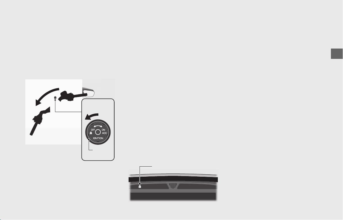
❙
Locking
a Turn the ignition switch to OFF. (P49)
b Turn the handlebars all the way to the
left or right.
c Turn the ignition switch
counterclockwise.
u The steering lock indicator comes on
briefly and the steering is
automatically locked.
u If the steering lock indicator blinks
and the alarm sounds, the steering
has not been locked completely
because the steering was not
positioned all the way to the left or
right.
If this occurs, reposition the
handlebars all the way to the left or
right, then turn the ignition switch
counterclockwise (The steering can
also be locked by positioning it all the
way to the left or right while the
alarm is sounding).
❙
Unlocking
!aMake sure that the
is activated (P56) and enter the
operating range.
(P57)
!bTurn the ignition switch clockwise.
u The steering is unlocked
automatically.
!b
Ignition
switch
!a !c
Steering lock indicator
Operation Guide
56
Honda SMART Key System
The Honda SMART Key system allows you
to operate the vehicle.
The system runs a two-way authentication
between the vehicle and the Honda SMART
Key to verify it is the registered Honda
SMART Key.
The Honda SMART Key system uses low-
intensity radio waves. It may affect medical
equipment such as a cardiac pacemakers.
Activate or Deactivate the Honda
SMART Key System
❙
To Switch the Honda SMART Key
System to Activation or Deactivation
Press and hold the ON/OFF button for more
than 1 second.
❙
To Check the Honda SMART Key
System Status
Press the ON/OFF button for less than 1
second. The LED of the Honda SMART Key
will show the status.
When the LED of the Honda SMART Key:
Blinks 3 times:
(activation)
Honda SMART Key
system authentication
can be performed.
Lights briefly:
(deactivation)
Honda SMART Key
system authentication
can not be performed.
LED
ON/OFF button
Operation Guide
57
continued
Operating Range
The Honda SMART Key system uses low-
intensity radio waves. Therefore its
operating range may become wider or
narrower, or the Honda SMART Key system
may not work properly in the following
environments.
• When the Honda SMART Key battery is
low or depleted.
• When there are facilities nearby that
generate strong radio waves or noise,
such as TV towers, power stations, radio
stations, or airports.
• When you carry the Honda SMART Key
with a laptop or wireless communication
device such as a radio or mobile phone.
• When the Honda SMART Key comes into
contact with or is covered by metal
objects.
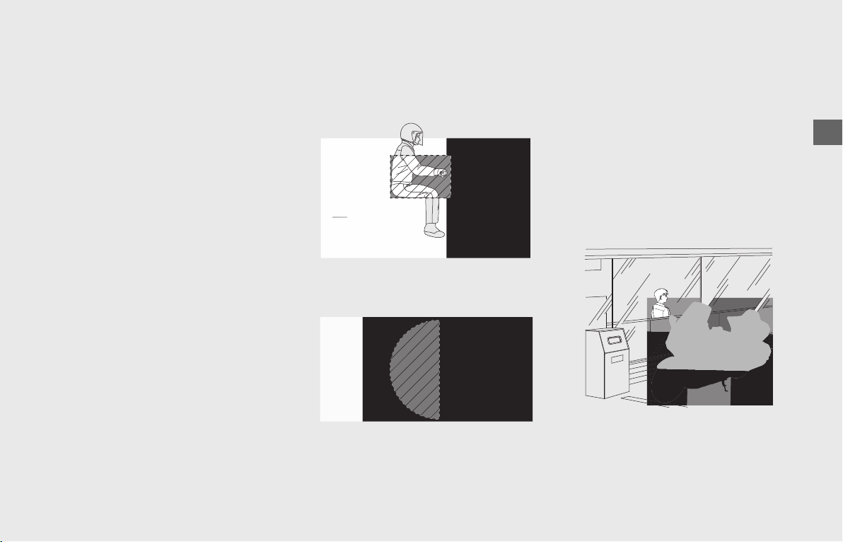
The system can be operated when the
Honda SMART Key is within the shaded
area shown in the illustration.
Anyone can operate the ignition switch and
start the engine if your Honda SMART Key
is within operating range of your vehicle,
even if you are on the other side of a wall
or window. If you will be away from your
vehicle but your Honda SMART Key will still
be within the system’s operating range,
deactivate the Honda SMART Key system.
Activate or Deactivate the Honda
SMART Key System
(P56)
Operation Guide
58
Honda SMART Key System (Continued)
Anyone in possession of the Honda SMART
Key can perform the following operations if
the Honda SMART Key is within the
system’s operating range:
• Unlocking the steering lock
(P55)
• Activating the electrical system (P58)
• Starting the engine (P112)
• Operating the audio system (P67) and
other accessories.
• Opening the travel trunk, saddlebags
and fairing pocket
(P128)
You should always keep the Honda SMART
Key on your person when you get on and
off the vehicle or while riding.
Do not place the Honda SMART Key in the
travel trunk ( ), saddlebags,
shelter case ( ) or fairing
pocket.
If the ignition switch is ON, the vehicle can
be operated even by a person who does
not have a verified Honda SMART Key.
Whenever you leave your vehicle, turn the
ignition switch to OFF and lock the
steering.
(P58)
Operating the Ignition Switch
❙
To Activate the Electrical System
aMake sure that the Honda SMART Key
is activated and enter the operating
range for the vehicle.
(P57)
bTurn the ignition switch to ON. (P49)
u The electrical system activates and
the engine can be started.
❙
To Turn Off the Electrical System
!!aTurn th
(Lock). (P49)
u The windscreen moves to the lowest
position automatically.
!bLeave the operating range
Honda SMART Key (P57) or switch
the Honda SMART Key system to
deactivation.
(P56)
Always make sure the ignition switch is
OFF.
If the Honda SMART Key System
Does Not Work Properly
(P188)
GL1800/D/DA
Except GL1800DA
Honda SMART Key
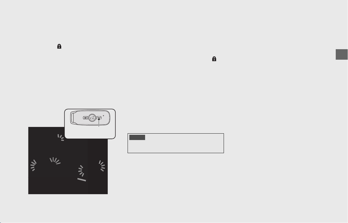
Operation Guide
59
Answer Back System
The answer back system is a device to find
the location of your vehicle. When you
press and hold the answer back button on
the Honda SMART Key with the ignition
switch OFF or (Lock), your vehicle
informs you the location by blinking the
turn signal lights, and sounding the horn
three times.
The answer back system uses low-intensity
radio waves. It may affect medical
equipment such as a cardiac pacemaker.
❙
Operation
Press and hold the answer back button on
the Honda SMART Key.
u The answer back system will not function
when the ignition switch is ON.
If the ignition switch is left in OFF or
(Lock) for more than 30 days, the answer
back system will no longer operate.
During the system is activating, when the
vehicle receives a signal by pressing the
answer back button, the system activation
will be extended for 30 days.
To reset the system, turn the ignition switch
ON once and then OFF.
u To turn the ignition switch ON (P49)
Answer back
button
NOTICE
When the battery in the vehicle is weak, the answer
back system may not function.
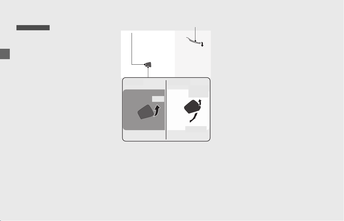
Operation Guide
60
Parking Brake
Parking Brake Lever
Be sure the parking brake is applied when
parked and warming up the engine.
u Make sure the parking brake lever is
released before riding.
To apply the parking brake:
Squeeze the front brake lever and pull the
parking brake lever back to lock the rear
wheel.
u The parking brake lock will not function
if the parking brake is not adjusted
properly.
(P166)
To release the parking brake:
Release the parking brake lever by lightly
pulling in the lever.
u Before riding, check that the parking
brake indicator is turned off and make
sure that the parking brake is fully
released so there is not drag on the rear
wheel.
GL1800BD/D/DA
Parking
brake lever
Squeeze
Front brake lever
Apply: Release:
Pull
Lightly
pull
Release
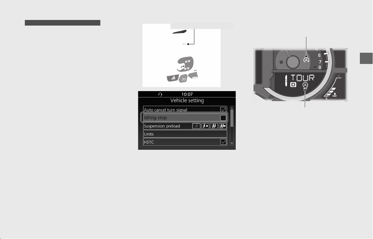
Operation Guide
61
Idling Stop System
The Idling Stop system is designed to help
reduce fuel consumption and noise by
stopping the engine from idling when
stopped, such as when waiting at an
intersection.
Switching the Idling Stop System
On or Off
Switch the Idling Stop system on or off
using the start/Idling Stop button or by the
setting menu in the multi-information
display.
(P28)
Each time the start/Idling Stop button is
pressed, the Idling Stop system is switched
on or off.
The status of the Idling Stop system (on or
off) is maintained when the ignition switch
is turned to OFF and then back to ON.
• ON: Idling Stop OFF indicator does not
come on.
u Idling Stop indicator comes on when
the Idling Stop system becomes ready
to stop the engine while riding. Idling
Stop indicator flashes when the
engine is stopped by the Idling Stop
system.
• OFF: Idling Stop OFF indicator comes on.
u Idling Stop OFF indicator comes on
when the Idling Stop system is off.
GL1800BD/D/DA Canada model only
Start/Idling Stop button
Idling Stop indicator
Idling Stop OFF indicator
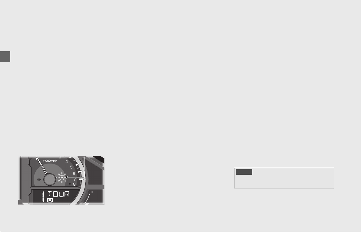
Operation Guide
62
Idling Stop System (Continued)
Activating the Idling Stop System
The Idling Stop system becomes ready to
stop the engine and the Idling Stop
indicator comes on when the following
conditions are satisfied with the Idling Stop
system on.
• Engine is sufficiently warmed up
• Vehicle has been ridden at a speed of
over 6 mph (10 km/h).
Idling Stop Indicator Does Not
Come On:
(P186)
Stopping the engine by the Idling Stop
System
The engine stops and the Idling Stop
indicator flashes after you close the throttle
completely and stop the vehicle while the
Idling Stop system is on.
u While the engine is stopped by the Idling
Stop system, if you press the start/Idling
Stop button, the Idling Stop system is
deactivated and the engine will restarts.
u The following conditions occurs while
the engine is stopped by the Idling Stop
system, the engine will be restarted.
- Hill Start Assist (HSA) is activated.
- Transmission is shifted in Neutral (N
side of the N-D switch is pressed).
- Vehicle moves at about 3 mph (5 km/h)
or more.
- Battery is discharged more than
specified.
u In the following conditions, the engine
will not stop by the Idling Stop system.
- Rider is not sitting astride the vehicle.
- Transmission is in Neutral (N).
- Battery is weak or temperature of
battery is low.
- Hill Start Assist (HSA) is operated.
Safety Precautions for the Idling Stop
System
Do not go away from the vehicle while the
Idling Stop indicator is flashing. When you
go away from the vehicle, always turn the
ignition switch to OFF.
u While the engine is stopped by the Idling
Stop system, do not press against the
seat with your hands or body, and do
not put a load on the seat other than
that of the rider sitting astride the
vehicle.
Even if the rider does not get on the
vehicle, the engine will restart
unexpectedly when the throttle is
opened or when the battery becomes
weak with a load on the seat.
Engine is Not Stopped by the
Idling Stop System While the
Idling Stop Indicator is On:
(P186)
Idling Stop indicator
NOTICE
Stopping by the Idling Stop system for a long time may
cause battery discharge.

Operation Guide
63
Restarting the Engine
Check that the Idling Stop indicator is
flashing, and then open the throttle.
The engine will not restart if the rider is not
sitting astride the vehicle.
When restarting on a slope, release the
brakes after you feel the vehicle begin to
move.
u If the indicator is not flashing, you
cannot restart the engine with the Idling
Stop system, even if you open the
throttle.
u In the following conditions while the
engine is stopped by the Idling Stop
system, the Idling Stop indicator changes
from flashing to off and you cannot
restart the engine, even if you open the
throttle.
- When the side stand is lowered
- When the vehicle has fallen over
- When the rider has not been sitting
astride the vehicle for approx. 3
minutes
To restart the engine when the Idling
Stop indicator not flashing, shift the
transmission into neutral and press the
start/Idling Stop button. (To restart
except in Neutral, apply the brake lever
firmly, and then press the start/Idling
Stop button.)
u The engine starts in the following
conditions without opening the throttle
grip.
- When changing the Idling Stop system
from on to off
- When the gear position is changed to
Neutral (N)
- When the vehicle moves by releasing
the brakes while stopped on a slope
- When the battery is weak
• A few seconds before restarting the
engine, the Idling Stop indicator
flashes quickly. After restarting, the
Idling Stop indicator turns off and the
system does not operate until the
battery voltage has recovered.
• See your dealer for checking the
battery.
- When the Hill Start Assist (HSA) system
is activated with the brakes applied
firmly
❙
Engine Does Not Start Even If the
Throttle is Opened: (P187)

Operation Guide
64
Airbag System
The Airbag System can help cushion the
impact force to the rider’s head and upper
body in certain severe frontal impacts.
For safety precautions, see “Airbag
system.”
(P11)
How Rider Injuries Occur in a
Frontal Crash
“SPEED KILLS,” a saying goes. But not all
vehicle injuries occur at high speeds, and
speed alone does not cause injuries.
In fact, the main cause of injuries in a
collision is a rapid decrease in speed, caused
by the rider impacting an object, such as
another vehicle or the ground. As another
saying goes, “It’s not how fast you go, it’s
how hard you hit.”
Consider, for example, what happens
when a vehicle and rider crash into a
parked car at 30 mph (50 km/h).
• In a 30 mph (50 km/h), head-on crash
into the side of a stationary car, the
vehicle will come to a stop in about 1/
10th of a second-nearly as fast as the
blink of an eye.
Without an airbag, the rider would
continue forward at 30 mph (50 km/h)
until he strikes the car or the ground
with a force that could cause very serious
or fatal injuries.
• In the same situation with an airbag-
equipped vehicle, the bag would slow
the rider’s forward movement and
absorb some of his kinetic energy.*
As a result, the rider would impact the car
and/or the ground at a lower speed and
with less force, and have a better chance of
surviving the crash.
*Kinetic energy (KE) is the energy of motion. For a
rider, it’s a combination of the rider’s mass (m) or
weight, and his speed (v).
Mathematically, KE = (m x v2)/2. At 30 mph (50
km/h), a rider’s kinetic energy is four times greater
than at 15 mph (24 km/h). At 45 mph (72 km/h), it
would be nine times greater.
At 60 mph (100 km/h), it would be sixteen times
greater.
• A crash into a solid barrier at 30 mph (50
km/h) may not seem very serious, but for
the rider it would be similar to falling
from a third-story building directly onto
pavement.
GL1800DA
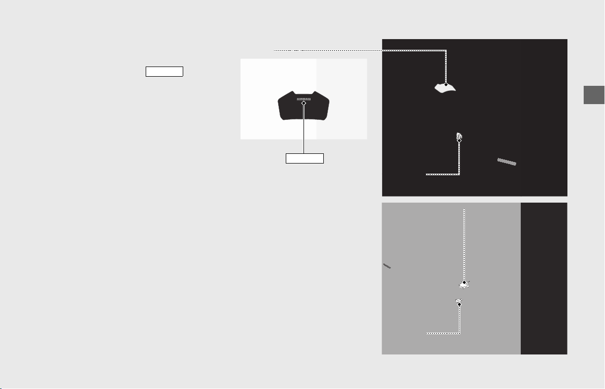
Operation Guide
65
Airbag System Components
Your vehicle airbag system includes:
An airbag that is stored forward of the rider’s
seat, under a cover marked .
The impact sensors that measure the rate of
deceleration during a frontal impact are
located on the left and right of the main
frame under the rider seat.
The control unit evaluates data from the
impact sensors and determines whether or
not the airbag should deploy.
The system continually monitors
information about the sensors, the control
unit, and the airbag inflator whenever the
ignition is in the ON position.
AIRBAG
Impact sensor
Impact sensor
Control unit
Airbag
mark
AIRBAG
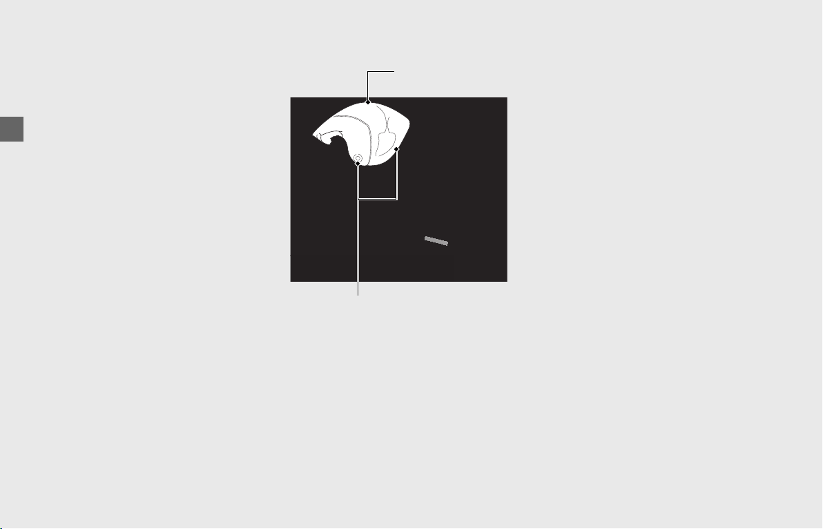
Operation Guide
66
Airbag System (Continued)
How The Airbag System Works
If you ever have a frontal impact, the
impact sensors will detect the vehicle’s
deceleration and send that information to
the control unit.
If the rate of deceleration is high enough,
the control unit will signal the airbag to
instantly inflate.
As the rider’s head and upper body press
into the airbag, the bag immediately begins
deflating, through vents located at the
bottom of the bag.
The airbag slows down the rider’s forward
movement and absorbs some of the rider’s
kinetic energy.
When the rider eventually separates from
the vehicle and contacts the opposing
object or the ground, the forward speed of
the rider and the resulting force of the
impact will be much lower than they would
be without the airbag.
Airbag System Service
Your airbag system is well protected from
the elements. There is no need to take any
special precautions to protect it from rain,
snow, or temperature extremes.
The airbag system is also virtually
maintenance free, and there are no parts
you can safely service. However, you must
have your vehicle checked by a Honda
dealer if:
• The AIRBAG indicator alerts you to a
potential problem with the system. The
indicator, located in the instrument
panel, should come on briefly when you
turn the ignition switch to ON. If it does
not come on, or it comes on and stays
on, or it comes on while you are riding,
the airbag may not deploy when you
need it.
• The airbag ever inflates. Any airbag that
has deployed must be replaced along
with the control unit and other related
parts. Do not try to remove or replace
the airbag by yourself. This must be done
by a Honda dealer.
Airbag
Vents

Operation Guide
67
Audio System
About Your Audio System
The audio system features AM/FM radio.
It can also play USB flash drives and iPod
®
,
iPhone
®
and Bluetooth
®
devices.
You can operate the audio system from the
switches on the left handlebar and buttons
on the center panel. However, you cannot
operate some functions by the center panel
switches/Interface dial while the vehicle is
in motion.
• State or local laws may prohibit the
operation of handheld electronic devices
while operating a vehicle.
• Only operate audio buttons and switches
when safe to do so.
• Set the volume at a level that still allows
horns and emergency vehicles to be
heard.
• Some audio devices, USB flash drives and
Bluetooth
®
audio devices may not be
compatible.
• Use any audio devices, USB flash drives
and Bluetooth
®
audio devices at your
own risk.
• In no event shall Honda be liable for any
damages or troubles that occur in the
use of audio devices and USB flash
drives.
• iPhone, iPad, iPad Air, iPad Mini, iPod,
iPod touch, iPod classic, iPod shuffle and
iPod nano are trademarks of Apple Inc.
•The Bluetooth
®
word mark and logos are
registered trademarks owned by
Bluetooth SIG, Inc., and any use of such
marks by Honda Motors Co., Ltd., is
under license.
• Other trademarks and trade names are
those of their respective owners.
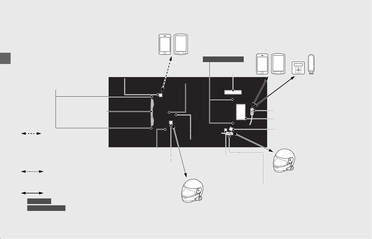
Operation Guide
68
Audio System (Continued)
Audio System Component Locations
iPhone/Mobile
phone, etc.
iPod/USB digital
audio player/USB
flash drive, etc.
Rider Bluetooth
®
headset
Passenger Bluetooth
®
headset
Audio unit
Radio antenna
Main Bluetooth
®
antenna
Front Bluetooth
®
antenna
Rear Bluetooth
®
antenna
Rear speakers
Except GL1800B/BD
Front speakers
GPS antenna
USB 1 connector
*
1
Left handlebar switches
Center panel
Multi-information
display
USB connection
(P94)
iPhone/Mobile
phone/Bluetooth
®
audio device, etc.
Audio system supported
profiles:
•HFP ver. 1.5
• A2DP ver. 1.2
•AVRCP ver. 1.4
• PBAP ver. 1.0
Headset supported profiles:
• HFP ver. 1.6 / ver. 1.5
• A2DP ver. 1.2
Bluetooth
®
connection (P82)
Bluetooth
®
connection (P82)
Bluetooth
®
connection
(P82)
USB connection:
*
1
: USB 1 connector is in the travel trunk.
*
2
: USB 1 connector is in the shelter case.
*
3
: Apple CarPlay cannot be used with USB connection via USB 2 connector.
GL1800DA
Except GL1800DA
USB 1 connector
*
2
USB 2 connector*
3
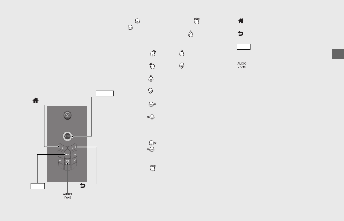
Operation Guide
69
Basic Operations
You can operate and set the various
functions of the audio system using the
interface dial and buttons on the center
panel and/or switches on the left
handlebar. However, you cannot operate
some functions by the center panel
switches/Interface dial while the vehicle is
in motion.
Center Panel
[1] (Interface dial): Rotate or move
in the eight possible directions to select
the available choices. Press to set your
selection.
• When listening to the radio
Rotate or move : Switches to a
higher-frequency
Rotate or move : Switches to a
lower-frequency
Move and hold: Selects the next
station with strong reception.
Move and hold: Selects the previous
station with strong reception.
Move : Selects the next preset radio
station.
Move : Selects the previous preset
radio station.
• When listening to an iPod, USB flash
drive or Bluetooth
®
audio
Move : Skips to the next song.
Move : Goes back to the beginning
of the current or previous song.
• While the vehicle is in motion
Rotate : Adjusts a volume of the
current audio mode.
[2] (Home) button: Select to go to the
home screen.
[3] (Back) button: Press to go return the
previous screen.
[4] button: Press to switch the
information displayed on the information
bar.
[5] button: Press to switch the audio
output between the paired Bluetooth
®
headsets and the speakers.
[1] Interface dial ( )
ENTER
[3] (Back) button
[2] (Home) button
[4] button
INFO
[5] button
INFO
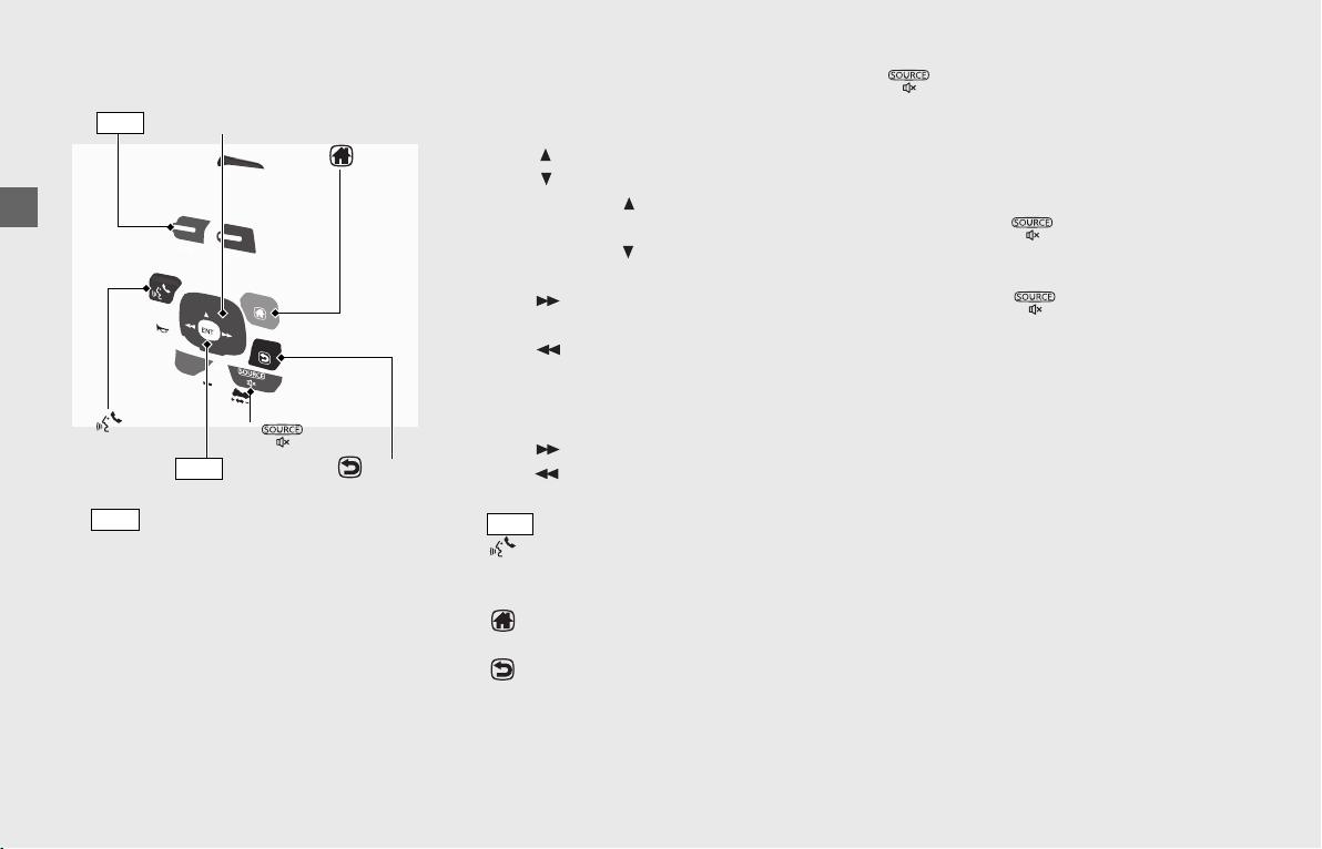
Operation Guide
70
Audio System (Continued)
Left Handlebar
[1] (volume control) lever: Push the
lever up to increase the volume.
• To increase the volume: Push the lever
up.
• To decrease the volume: Push the lever
down.
• To increase the volume rapidly: Push up
and hold the lever.
• To decrease the volume rapidly: Push
down and hold the lever.
[2] 4-way key switch: Press right, left, up or
down to select a menu item.
• When listening to the radio
Press : Switches to a higher-frequency.
Press : Switches to a lower-frequency.
Press and hold : Selects the next
station with strong reception.
Press and hold : Selects the previous
station with strong reception.
Press : Selects the next preset radio
station.
Press : Selects the previous preset
radio station
• When listening to an iPod, USB flash
drive or Bluetooth
®
audio
Press : Skips to the next song.
Press : Goes back to the beginning of
the current or previous song.
[3] switch: Press to set your selection.
[4] (Voice control) switch: Press to
receive, reject or end a call. Starts Siri if
Apple CarPlay is available.
[5] (Home) switch: Select to go to the
home screen.
[6] (Back) switch: Press to return to the
previous screen.
[7] (Source/Private Mode) switch:
Press to change the audio mode. Cycles
through the audio modes as follows:
[FM] → [AM] → [SXM] (option) → [USB] →
[iPod] → [Bluetooth] → [AUX] (option)
• When playing an audio
Press and hold switch to mute the
volume and to pause a track
• When receiving a call
Press and hold switch to enable/
disable the private mode.
[2] 4-way key switch
[3] switch
ENT
[7] switch
[5] switch
[6] switch
[1] lever
VOL
[4] switch
VOL
ENT
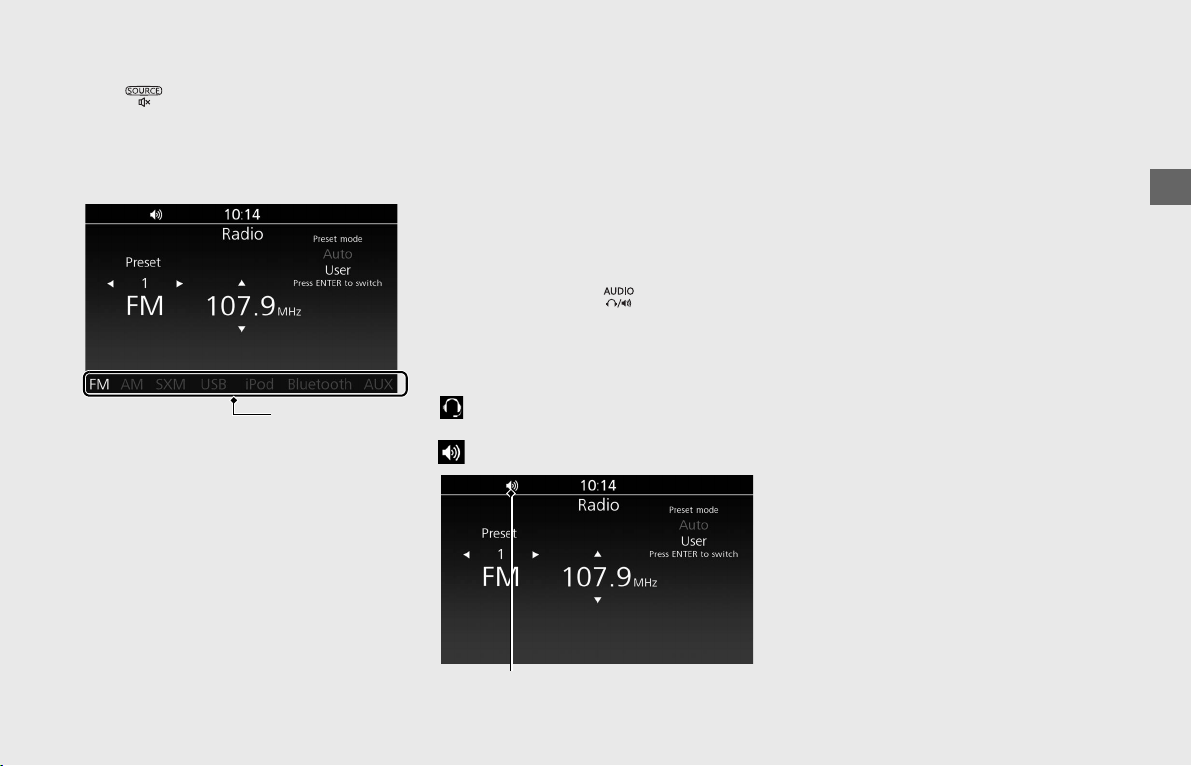
Operation Guide
71
continued
❙
To Change the Audio Mode
Press switch to change the audio
mode. Cycles through the audio modes on
the information bar as follows:
[FM] → [AM] → [SXM] (option) → [USB] →
[iPod] → [Bluetooth] → [AUX] (option)
•[FM] (P92)
•[AM] (P92)
• [SXM]
This function is optional. Optional
antenna kit and subscription of
SiriusXM
®
are required. Contact your
dealer for details.
SiriusXM
®
is a registered trademark of
SiriusXM Radio, Inc.
•[USB]
(P98)
• [iPod] (P98)
• [Bluetooth] (P98)
•[AUX]
This function is optional. Contact your
dealer for details.
❙
To Select the Audio Output Device
You can switch the audio output between
the paired Bluetooth
®
headsets and the
speakers by pressing button on the
center panel.
The selected device is displayed by the
audio output status icon on the screen.
: Audio output is from the Bluetooth
®
headsets.
: Audio output is from the speakers.
❙
To Adjust the Volume
You can adjust the volume settings for the
speakers and headsets separately.
The system has following unique volume
levels. Adjust the volume while in the
individual modes.
[Audio vol.]/[Navi vol.]/[Ring tone vol.]/
[Phone vol.]/[CB vol. (option)]
Each volume can also be set from the
menu.
(P76)
While the vehicle is in motion, you can
adjust the volume of the current audio
mode by rotating the interface dial.
(P69)
Information bar
Audio output status icon
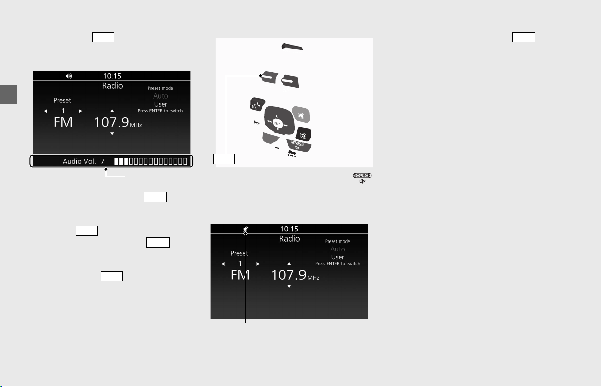
Operation Guide
72
Audio System (Continued)
When you push lever up or down,
the volume control level appears on the
information bar.
To increase the volume: push lever
up.
uTo increase the volume rapidly, push up
and hold lever.
To decrease the volume: push lever
down.
uTo decrease the volume rapidly, push
down and hold lever.
VOLUME level range: Level 0 to 30
To mute the volume: Press and hold
switch.
uA diagonal line appears in the audio
output status icon on the screen.
To resume the volume: Operate lever
while volume is muted.
VOL
Information bar
VOL
VOL
VOL
VOL
lever
VOL
Audio output status icon
VOL
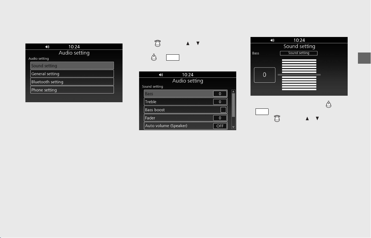
Operation Guide
73
Audio Setting
From this screen, you can go to various
setup options for the audio system.
• [Sound setting]
(P73)
• [General setting] (P77)
• [Bluetooth setting] (P82)
• [Phone setting] (P90)
❙
Sound Setting
You can adjust the sound to fit your
preferences.
Rotate or press / on the 4-way
key switch to select a setting menu.
Press or switch to set your
selection.
The sound settings contain the following:
• [Bass] (P73)
•[Treble] (P74)
• [Bass boost] (P74)
•[Fader] (P74)
• [Auto volume (Speaker)] (P75)
• [Auto volume (Headset)] (P75)
•[Volume] (P76)
• [CB roger beep] (P76)
Bass
Adjusts lower-frequency sound level.
!aSelect [Bass], and then press or
switch.
!bRotate or press / on the 4-
way key switch to select your preferred
level.
!cReturn to the previous screen or the
Home screen.
(P24)
Available setting range: Level -6 to +6
Default: Level 0
The Bass control is automatically adjusted
in accordance with the vehicle speed.
ENT
ENT
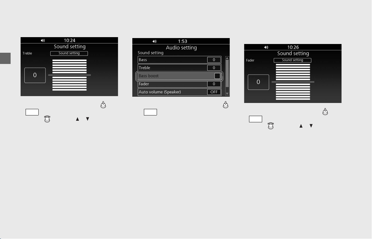
Operation Guide
74
Audio System (Continued)
Treble
Adjusts higher-frequency sound level.
!a Select [Treble], and then press or
switch.
!b Rotate or press / on the 4-
way key switch to select your preferred
level.
!c Return to the previous screen or the
Home screen.
(P24)
Available setting range: Level -6 to +6
Default: Level 0
The Treble control is automatically adjusted
in accordance with the vehicle speed.
Bass Boost
Enables/disables bass boost.
!aSelect [Bass boost], and then press
or switch to select (enable) or
deselect (disable) the function.
!bReturn to the previous screen or the
Home screen. (P24)
Default: Off (deselected)
Fader
Adjusts the front and rear speaker output
balance.
!aSelect [Fader], and then press or
switch.
!bRotate or press / on the 4-
way key switch to select your preferred
level.
uPositive levels increase front output
level and decrease rear output level. If
fader level is set to +7, the rear
speakers are muted.
uNegative levels decrease front output
level and increase rear output level. If
fader level is set to -7, the front
speakers are muted.
ENT
ENT
ENT
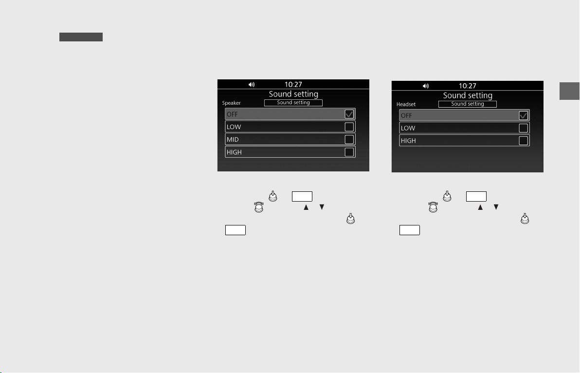
Operation Guide
75
u On models equipped
with the front speakers only, setting
the fader level to a negative level
means the output sound gradually
becomes smaller.
uThe fader setting does not affect the
headsets output.
!c Return to the previous screen or the
Home screen.
(P24)
Available setting range: Level -7 to +7
Default: Level 0
Auto Volume (Speaker)
Selects the volume setting to automatically
increase volume from the speakers as the
speed of the vehicle increases.
!a Select [Auto volume (Speaker)], and
then press or switch.
!b Rotate or press / on the 4-
way key switch, and then press or
switch to set your selection.
!c Return to the previous screen or the
Home screen.
(P24)
Available settings: [OFF]/[LOW]/[MID]/
[HIGH]
Default: [OFF]
Auto Volume (Headset)
Selects the volume setting to automatically
increase volume from the headsets as the
speed of the vehicle increases.
!aSelect [Auto volume (Headset)], and
then press or switch.
!bRotate or press / on the 4-
way key switch, and then press or
switch to set your selection.
!cReturn to the previous screen or the
Home screen.
(P24)
Available settings: [OFF]/[LOW]/[HIGH]
Default: [OFF]
GL1800B/BD
ENT
ENT
ENT
ENT
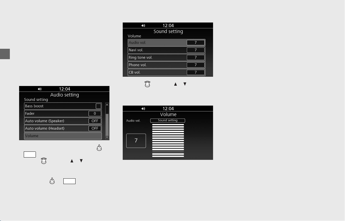
Operation Guide
76
Audio System (Continued)
Volume
Adjusts the volumes in the following modes
individually.
[Audio vol.]/[Navi vol.]/[Ring tone vol.]/
[Phone vol.]/[CB vol. (option)]
This setting is reflected as each volume of
the audio output device (speakers and
headsets) at that time. Select the audio
output device before settings.
(P71)
!a Select [Volume], and then press or
switch.
!b Rotate or press / on the 4-
way key switch to select the mode that
you want to adjust the volume, and
then press or switch to set
your selection.
!cRotate or press / on the 4-
way key switch to select your preferred
level.
!dReturn to the previous screen or the
Home screen.
(P24)
VOLUME level range: Level 0 to 30
Default: Level 7
Each volume can also be adjusted in
individual modes. (P71)
CB Roger Beep
Roger Beep is a beep sound that is sent to
notify you of the end of transmission.
This function is optional. Contact your
dealer for details.
ENT
ENT
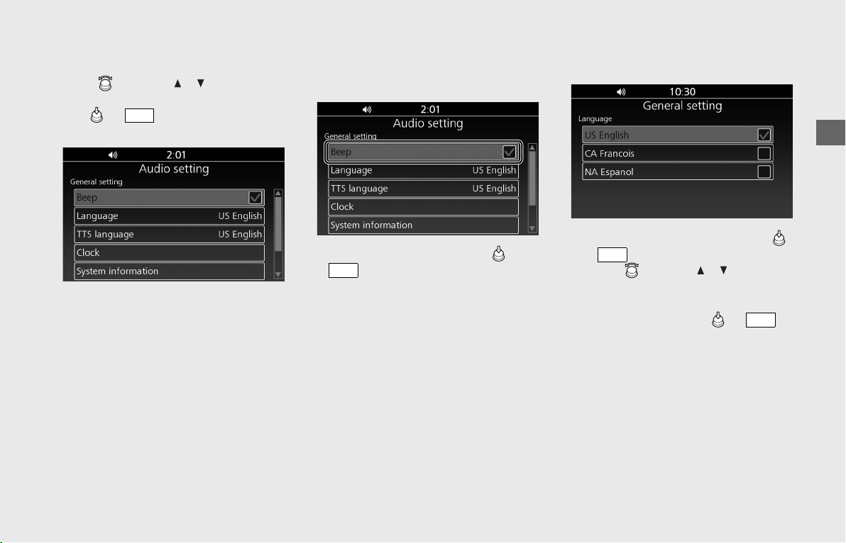
Operation Guide
77
❙
General Setting
Configures system settings.
Rotate , or press / on the 4-way
key switch to select a setting menu.
Press or switch to set your
selection.
The general settings contain the following:
• [Beep] (P77)
• [Language] (P77)
• [TTS Language] (P78)
• [Clock] (P78)
• [System Information] (P80)
• [Apple CarPlay/iPod] (P80)
• [System Reset] (P80)
• [Restore Apple CarPlay Settings] (P81)
Beep
Enables/disables the beep sound when
operating keys.
!a Select [Beep], and then press or
switch to select (enable) or
deselect (disable) the function.
uYou cannot deactivate the beep
sound for error or caution messages.
!b Return to the previous screen or the
Home screen.
(P24)
Default: On (selected)
Language
Changes the system language.
!aSelect [Language], and then press
or switch.
!bRotate or press / on the 4-
way key switch to select the display
language that you want to use on the
screen, and then press or
switch to set your selection.
!cReturn to the previous screen or the
Home screen.
(P24)
Available languages: [US English]/
[CA Francois]/[NA Espanol]
Default: [US English]
ENT
ENT
ENT
ENT
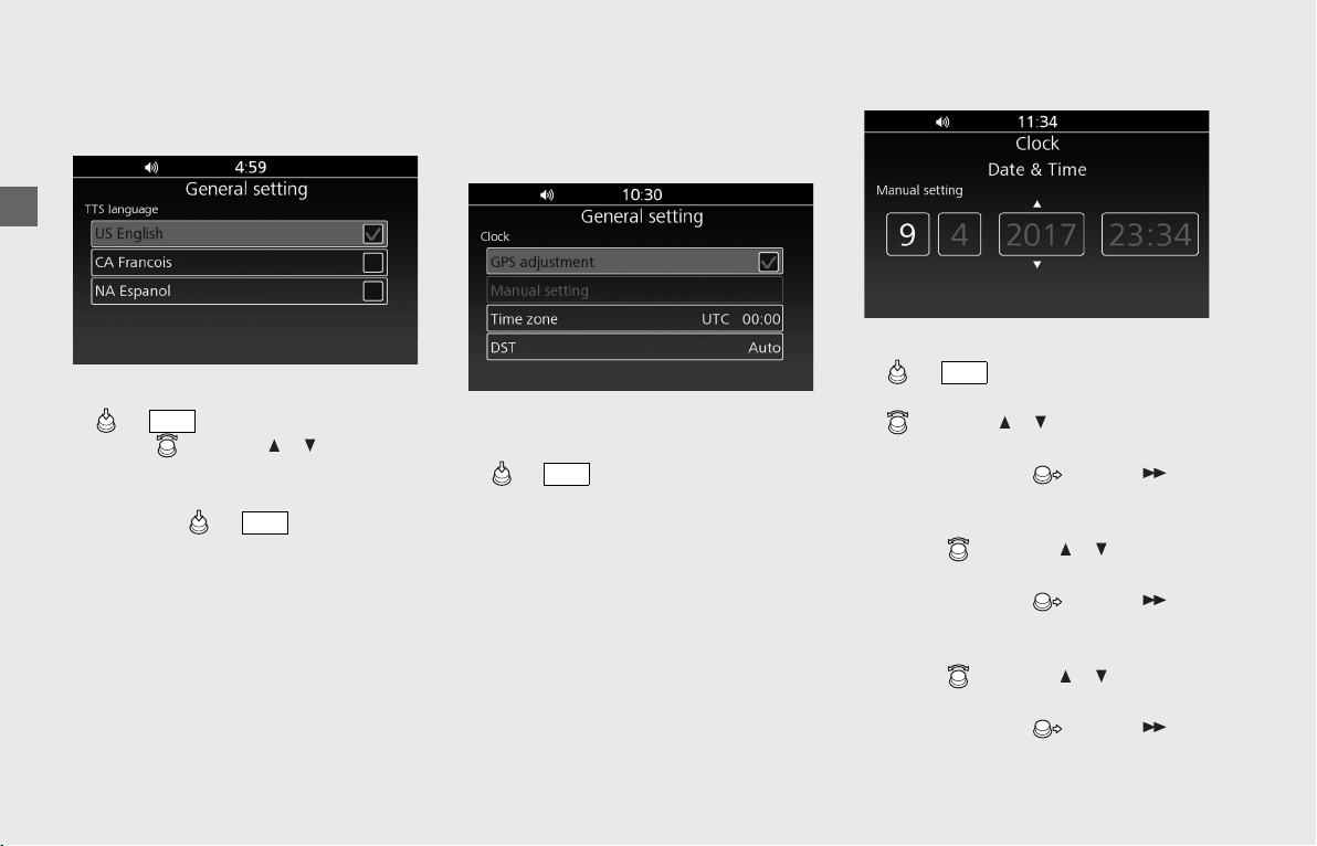
Operation Guide
78
Audio System (Continued)
TTS Language
Changes the TTS (text-to-speech)
language.
!a Select [TTS language], and then press
or switch.
!b Rotate or press / on the 4-
way key switch to select the TTS
language to use the navigation, and
then press or switch to set
your selection.
!c Return to the previous screen or the
Home screen.
(P24)
Available languages: [US English]/
[CA Francois]/[NA Espanol]
Default: [US English]
Clock
The audio system receives signals from GPS
satellites, updating the clock automatically.
You can also adjust the clock manually.
To enable/disable GPS adjustment function:
!aWith [GPS adjustment] selected, press
or switch to select (enable) or
deselect (disable) the function.
!bReturn to the previous screen or the
Home screen.
(P24)
Default: On (selected)
To adjust the clock manually:
!aSelect [Manual setting], and then press
or switch.
!bThe month section is selected. Rotate
or press / on the 4-way key
switch until the desired month is
displayed. Move or press on
the 4-way key switch to set the month.
The selection move to the day section.
!cRotate or press / on the 4-
way key switch until the desired day is
displayed. Move or press on
the 4-way key switch to set the day. The
selection move to the year section.
!dRotate or press / on the 4-
way key switch until the desired year is
displayed. Move or press on
the 4-way key switch to set the year.
The selection move to the hour section.
ENT
ENT
ENT
ENT
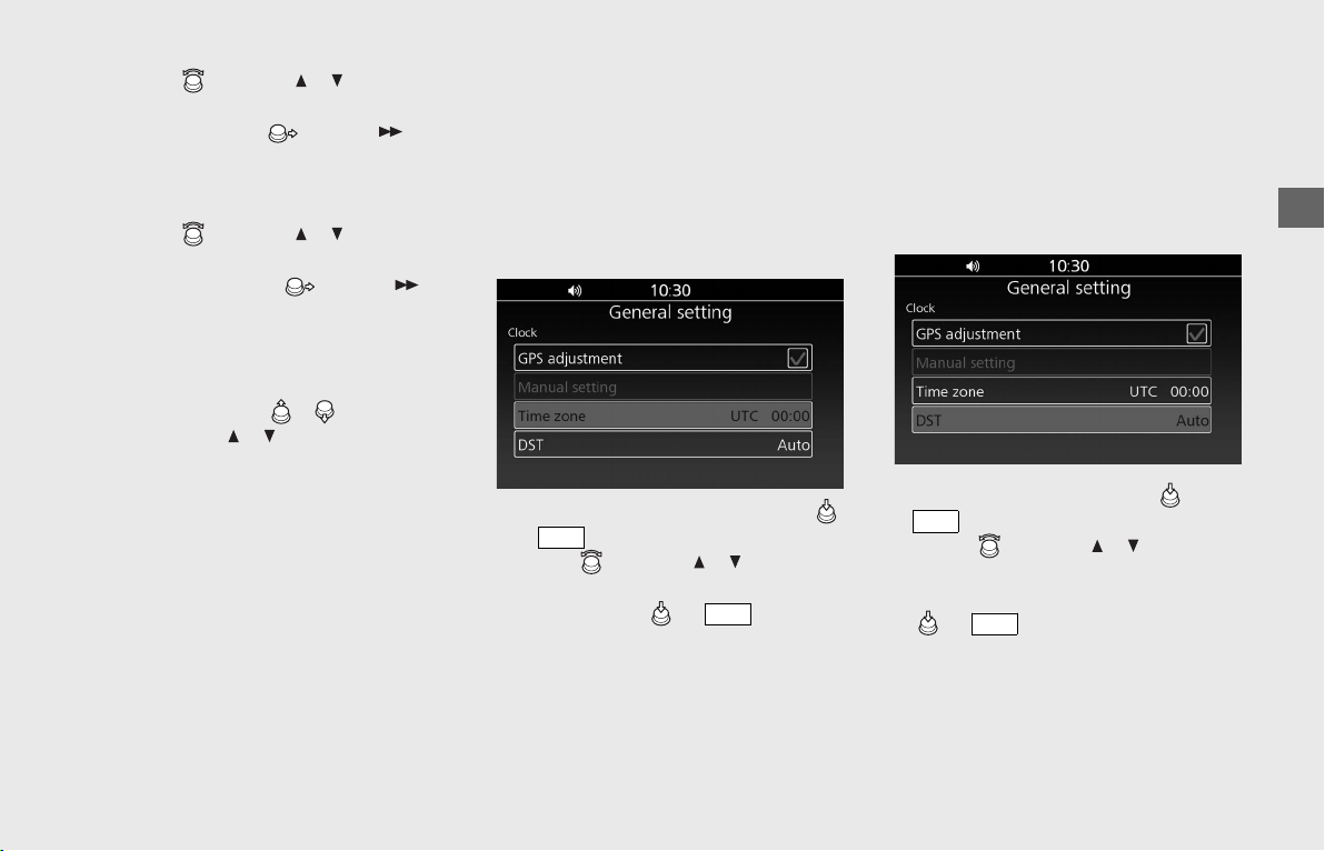
Operation Guide
79
!e Rotate or press / on the 4-
way key switch until the desired hour is
displayed. Move or press on
the 4-way key switch to set the hour.
The selection move to the minute
section.
!f Rotate or press / on the 4-
way key switch until the desired minute
is displayed. Move or press on
the 4-way key switch to set the minute.
!g Return to the previous screen or the
Home screen.
(P24)
Quick setting: Move / and hold, or
press and hold / on the 4-way key
switch until the desired number appears.
The clock setting is 24-hour indication, but
the clock display is 12-hour indication. The
call history is 24-hours indication.
The clock will be reset to 12:00 when the
battery is reconnected.
Time Zone
Selects the offset of local time from UTC
(Coordinated Universal Time).
This function is disabled when [Manual
setting] is selected. If you are in an area
outside the range of the navigation map,
[Auto] is disabled. When no GPS Signal
such as in tunnel will also disable [Auto].
!a Select [Time zone], and then press
or switch.
!b Rotate or press / on the 4-
way key switch to select the time zone,
and then press or switch to
set your selection.
Setting range: [Auto] or [UTC-12:00]
to [UTC +13:00]
!c Return to the previous screen or the
Home screen.
(P24)
DST
Sets the DST (Daylight Saving Time).
This function is disabled when [Manual
setting] is selected. If you are in an area
outside the range of the navigation map,
[Auto] is disabled. When no GPS Signal
such as in tunnel will also disable [Auto].
!aSelect [DST], and then press or
switch.
!bRotate or press / on the 4-
way key switch to select [Auto], ON
(enable) or OFF (disable), and then press
or switch to set your
selection.
!cReturn to the previous screen or the
Home screen.
(P24)
ENT
ENT
ENT
ENT
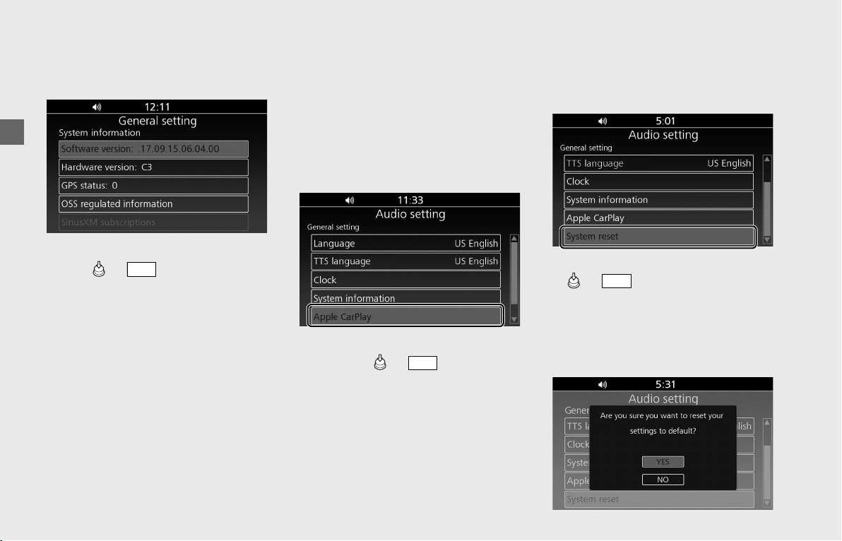
Operation Guide
80
Audio System (Continued)
System Information
Shows various information of the audio
system.
!a Select [System information], and then
press or switch.
!b The following information is displayed.
•Software version
•Hardware version
•GPS reception status
•OSS Regulated Information
•SiriusXM
®
Subscriptions: Displays
information about SiriusXM
®
subscriptions. This function is optional.
Contact your dealer for details.
!c Return to the previous screen or the
Home screen.
(P24)
Apple CarPlay/iPod
Selects whether Apple CarPlay connection
or iPod (USB) connection is used when
connecting your iPhone to the system with
a USB cable.
To change the connection setting,
disconnect the USB cable from your iPhone
once, change the setting menu, and then
connect the USB cable to your iPhone again.
!aSelect [Apple CarPlay] or [iPod], and
then press or switch to
change the connection.
Default: [Apple CarPlay]
!bReturn to the previous screen or the
Home screen. (P24)
Apple CarPlay: (P101)
Playing an audio: (P98)
System Reset
Resets the audio system to the factory
defaults. All settings including preset data
will be reset default values.
!aSelect [System reset], and then press
or switch.
uA confirmation message appears on
the screen.
!bSelect [YES] to reset the settings.
uAfter selecting [YES], the system will
reboot.
ENT
ENT
ENT
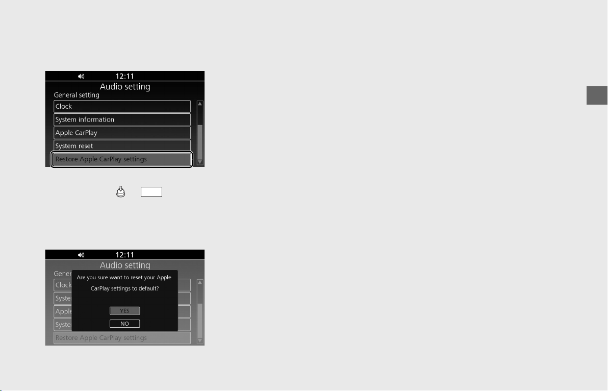
Operation Guide
81
Restore Apple CarPlay Settings
Resets your selection on the Apple CarPlay
disclaimer screen.
!a Select [Restore Apple CarPlay settings],
and then press or switch.
uA confirmation message appears on
the screen.
!b Select [YES] to reset your Apple CarPlay
setting.
!c Return to the previous screen or the
Home screen. (P24)
Apple CarPlay: (P101)
ENT
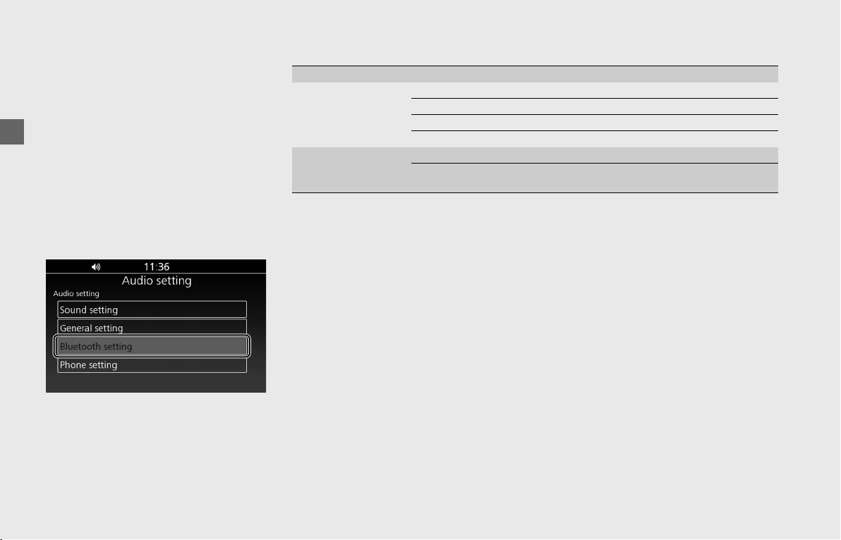
Operation Guide
82
Audio System (Continued)
❙
Bluetooth Setting
You can connect with your iPhone or other
mobile phone and/or Bluetooth
®
headsets
via Bluetooth
®
.
Your vehicle can establish up to 3
Bluetooth
®
connections at the same time.
Available devices are as follows:
• [Phone pairing] (For iPhone or mobile
phone) (P83)
• [Rider HS pairing] (For rider headset)
(P88)
• [Passenger HS pairing] (For passenger
headset) (P88)
Supported Bluetooth
®
version/profiles
• You cannot pair an iPhone/Bluetooth
®
device while the vehicle is moving. When pairing,
park your vehicle in a safe place.
• Bluetooth
®
connection cannot be established while launching Apple CarPlay.
• Your vehicle is not equipped with intercom function. If you want to use intercom
function, use the intercom function of your headset.
• Some local governments prohibit the use of a headset by the operator of a motor
vehicle. Always obey applicable laws and regulations.
Bluetooth
®
version Bluetooth 2.1 + EDR
Bluetooth
®
profiles
(For iPhone, mobile
phone or Bluetooth
®
device)
HFP (Hand Free Profile) ver. 1.5
A2DP (Advanced Audio Distribution Profile) ver. 1.2
AVRCP (Audio/Video Remote Control Profile) ver. 1.4
PBAP (Phone Book Access Profile) ver. 1.0
Bluetooth
®
profiles
(For rider and
passenger headsets)
HFP (Hand Free Profile) ver. 1.6 (recommendation) / ver. 1.5
A2DP (Advanced Audio Distribution Profile) ver. 1.2
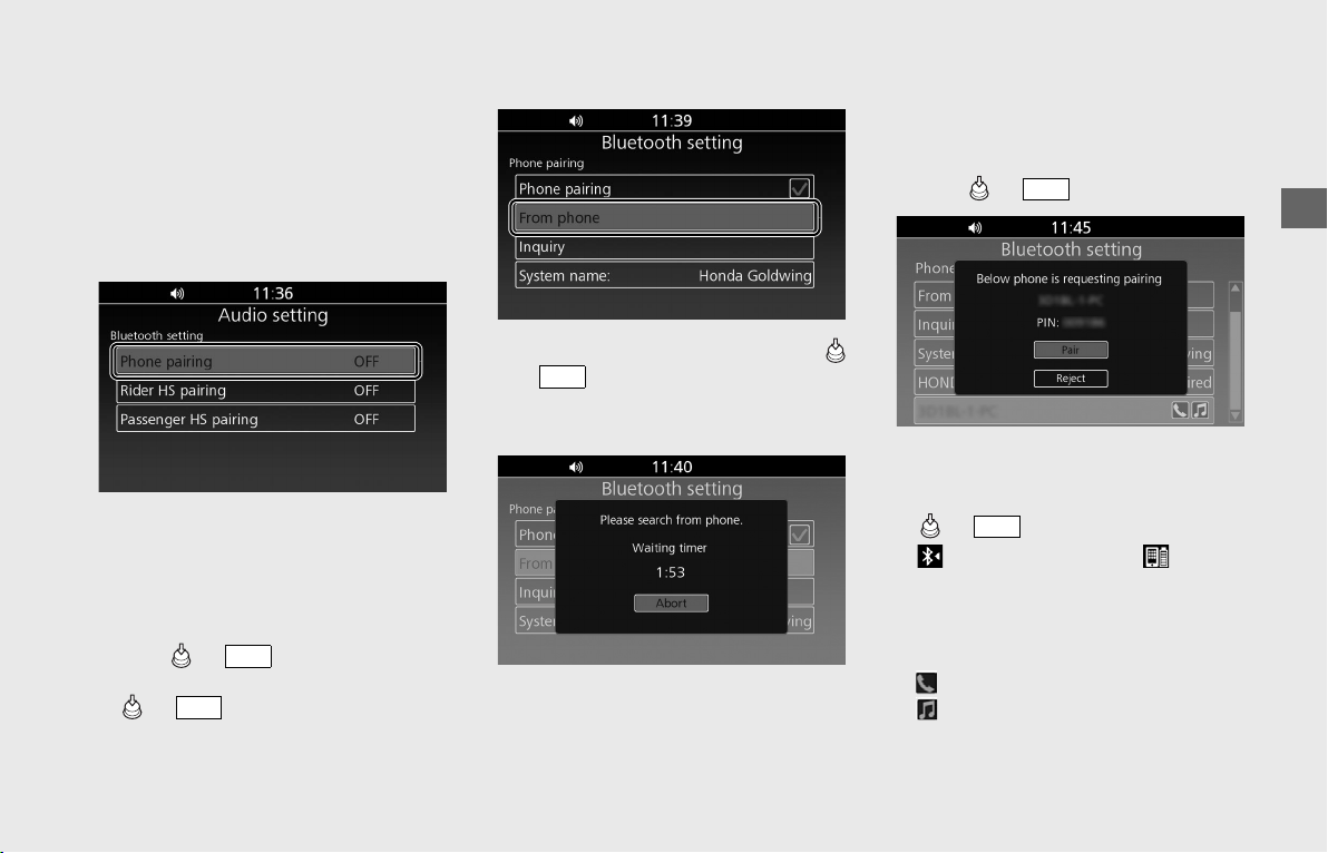
Operation Guide
83
continued
Phone Pairing
You can establish a Bluetooth
®
connection
in two ways.
• [From phone]: Search from the device.
• [Inquiry]: Search from the system.
This function is disabled while the vehicle is
in motion.
!a Enable the Bluetooth
®
function on your
device.
uFor details, refer to the instruction
manual of your device.
!b Select [Bluetooth setting], and then
press or switch.
!c Select [Phone pairing], and then press
or switch to enter the setting
menu.
[From phone]
!d Select [From phone], and then press
or switch.
uThe system waits for a response from
a target device for 2 minutes.
!e Tap “Honda Goldwing (default name)”
on the Bluetooth
®
setting menu of the
target device.
!fWhen a request message appears on
the target device, tap “Pair.”
!gThe device name and PIN code appear
on the screen. Select [Pair], and then
press or switch.
!hWhen the pairing is complete, a
message to inform you that pairing was
successful appears on the screen. Press
or switch.
!i (Bluetooth
®
icon) and (device
icon) appear on the upper part of the
screen, and icons of available functions
appear next to the name of the device
and turn on in light blue.
: Phone
: Music
!jReturn to the previous screen or the
Home screen.
(P24)
ENT
ENT
ENT
ENT
ENT
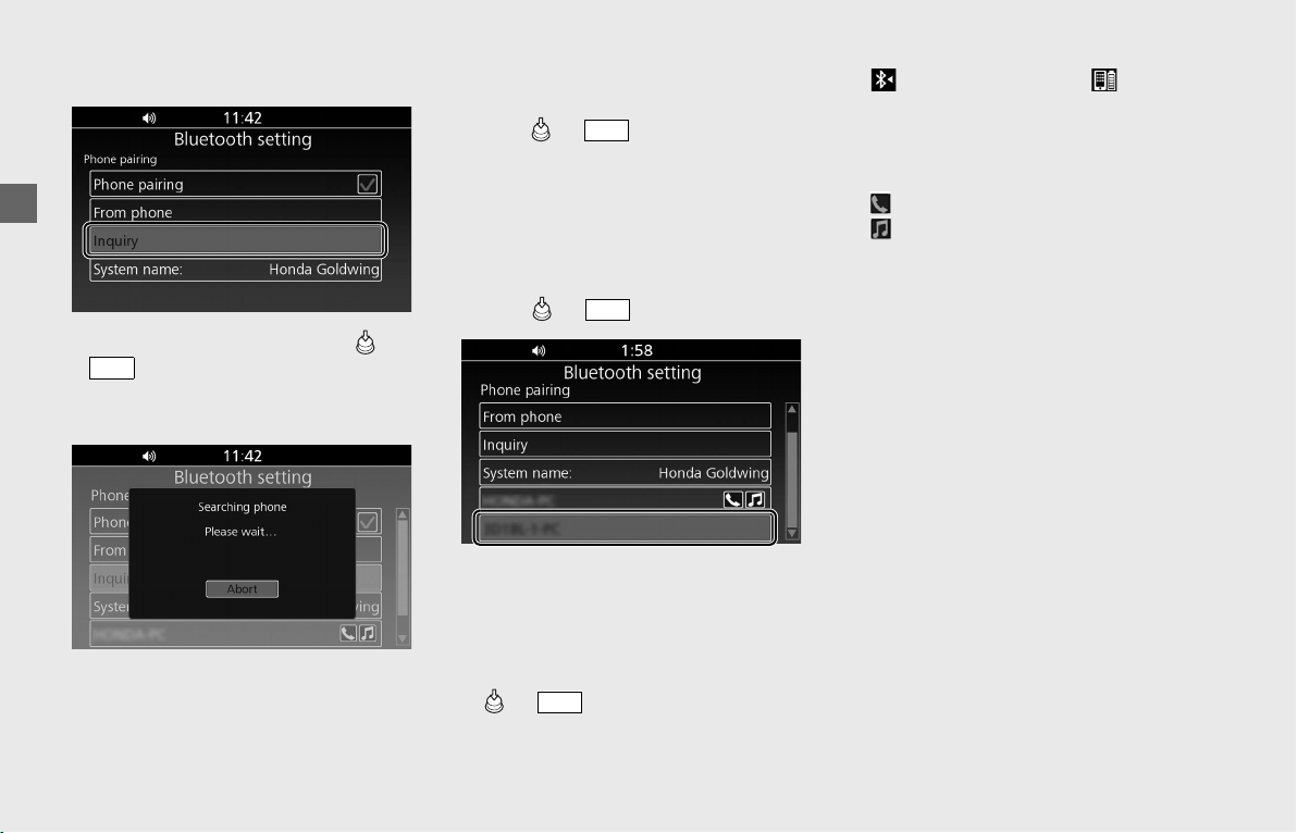
Operation Guide
84
Audio System (Continued)
[Inquiry]
!d Select [Inquiry], and then press or
switch.
uThe system waits for a response from
a target device.
!eThe names of the devices detected are
displayed on the background screen.
Press or switch to exit the
search mode.
uIf many Bluetooth
®
devices are
detected, the target device may be
detected under the list, so exit the
search screen and scroll down the list.
!fSelect a target device name, and then
press or switch.
!gWhen a request message appears on
the target device, tap “Pair.”
!hWhen the pairing is complete, a
message to inform you that pairing was
successful appears on the screen. Press
or switch.
!i (Bluetooth
®
icon) and (device
icon) appear on the upper part of the
screen, and icons of available functions
appear next to the name of the device
and turn on in light blue.
: Phone
: Music
!jReturn to the previous screen or the
Home screen.
(P24)
ENT
ENT
ENT
ENT
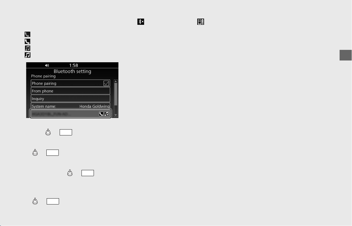
Operation Guide
85
To Connect the Paired Device Manually
Icon status:
(light blue) : phone function connected
: phone function unconnected
(light blue) : music function connected
: music function unconnected
!a Select [Bluetooth setting], and then
press or switch.
!b
Select [Phone pairing], [Rider HS pairing]
or [Passenger HS pairing], and then press
or
switch to enter the setting
menu.
!c Select the device you want to connect,
and then press or switch.
!d When the connection is established, a
message to inform you that pairing was
successful appears on the screen. Press
or switch.
!e (Bluetooth
®
icon) and (device
icon) appear on the upper part of the
screen, and icons of available functions
appear next to the name of the device
and turn on in light blue.
u
The battery status of the device icon is
displayed only when Phone connection
is established.
To Reconnect a Paired Device
Automatically
When the ignition switch is turned ON or
ACC, the system reconnects with
registered device automatically.
u If the system finds multiple paired
devices, the system will reconnect with
the device that was connected last.
u After reconnecting, the song that was
last played will be played automatically.
ENT
ENT
ENT
ENT
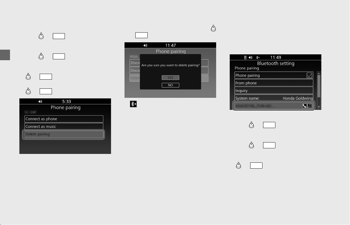
Operation Guide
86
Audio System (Continued)
To Delete the Paired Device
!a Select [Bluetooth setting], and then
press or switch.
!b Select [Phone pairing], [Rider HS pairing]
or [Passenger HS pairing], and then
press or switch to enter the
setting menu.
!c Select the paired device, and then press
or switch.
!d Select [Delete pairing], and then press
or switch.
!eA confirmation message appears on the
screen. Select [YES], and then press
or switch.
!f (Bluetooth
®
icon) disappears from
the screen.
To Connect/Disconnect Available
Functions Individually
Depending on the connected device, this
function may not be able to establish a
connection.
!aSelect [Bluetooth setting], and then
press or switch.
!bSelect [Phone pairing], [Rider HS pairing]
or [Passenger HS pairing], and then
press or switch to enter the
setting menu.
!cSelect the paired device, and then press
or switch.
ENT
ENT
ENT
ENT
ENT
ENT
ENT
ENT
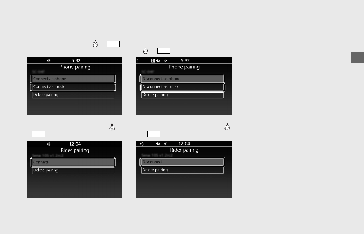
Operation Guide
87
To connect functions:
!d [Phone pairing]
Select [Connect as phone] or [Connect
as music], and
then press or
switch
.
[Rider HS pairing] / [Passenger HS pairing]
Select [Connect], and then press or
switch
.
!e Icon of selected function next to the
name of the device turns on.
To disconnect functions:
!d [Phone pairing]
Select [Disconnect as phone] or
[Disconnect as music], and then press
or switch
.
[Rider HS pairing] / [Passenger HS pairing]
Select [Disconnect], and then press
or switch
.
!e Icon of selected function next to the
name of the device turns off.
ENT
ENT
ENT
ENT
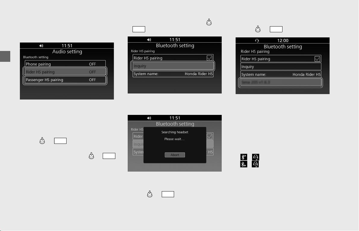
Operation Guide
88
Audio System (Continued)
Rider HS Pairing/Passenger HS Pairing
This function is disabled while the vehicle is
in motion.
!a Enable the Bluetooth
®
function on your
device.
uFor details, refer to the instruction
manual of your device.
!b Select [Bluetooth setting], and then
press or switch.
!c Select [Rider HS pairing] or [Passenger
HS pairing], and then press or
switch to enter the setting menu.
!dSelect [Inquiry], and then press or
switch.
uThe system searches for a target
device.
!eThe names of the devices detected are
displayed on the background screen.
Press or switch to exit the
search mode.
!fSelect a target device name, and then
press or switch.
!gWhen the pairing is complete, a
message to inform you that pairing was
successful appears on the screen.
Depending on the connection, the
following icon appears on the upper
part of the screen, and icons of available
functions appear next to the name of
the device and turn on in light blue.
/ : when pairing rider headset
/ :
when pairing passenger headset
!hReturn to the previous screen or the
Home screen.
(P24)
To connect/disconnect the headset:
(P85)
ENT
ENT
ENT
ENT
ENT
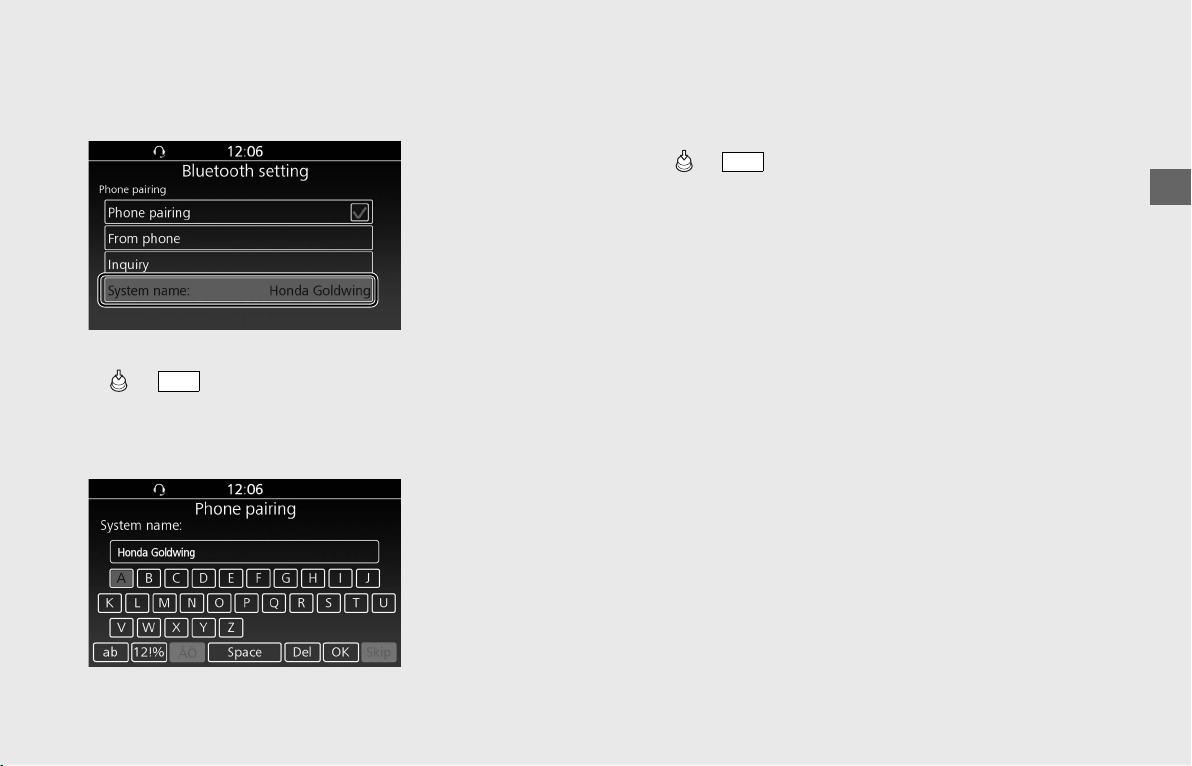
Operation Guide
89
To Edit the System Name
You can edit the system name to be
displayed on a target device.
!a Select [System name:], and then press
or switch.
!b The edit screen appears. Delete the
current name, and then enter the new
name.
System default name: Honda Goldwing
Headset default name: Honda Rider HS /
Honda Passenger HS
!c Select [OK], and then press or
switch.
ENT
ENT
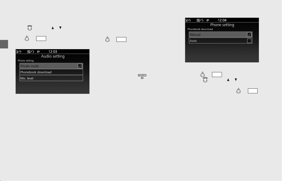
Operation Guide
90
Audio System (Continued)
❙
Phone Setting
You can configure the phone settings.
Rotate or press / on the 4-way
key switch to select a setting menu item.
Press or switch to set your
selection.
The phone settings contain the following:
• [Private mode] (P90)
• [Phonebook download] (P90)
• [Mic. level] (P91)
Private Mode
Enables/disables a call with the passenger's
headset.
!aSelect [Private mode], and then press
or switch to select (enable) or
deselect (disable) the function.
!bReturn to the previous screen or the
Home screen. (P24)
Default: On (selected)
This setting can also be configured by
pressing and holding switch on the
left handlebar during a call.
Phonebook Download
Enables/disables automatic import of your
phonebook and call history when your
phone is paired.
Up to 1,000 phonebook entries can be
stored.
uFor each person, you can store up to
4 numbers (home, office, cell phone and
other) in the phonebook.
Phonebook is updated after every
connection. Call history is updated after
every connection or call.
!aSelect [Phonebook download], and then
press or switch.
!bRotate or press / on the 4-
way key switch to select [Auto] or
[Manual], and then press or
switch.
!cReturn to the previous screen or the
Home screen. (P24)
Default: Auto
ENT
ENT
ENT
ENT
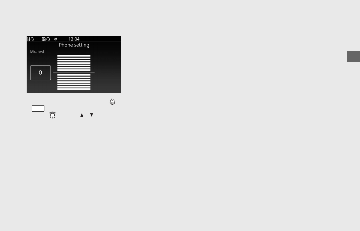
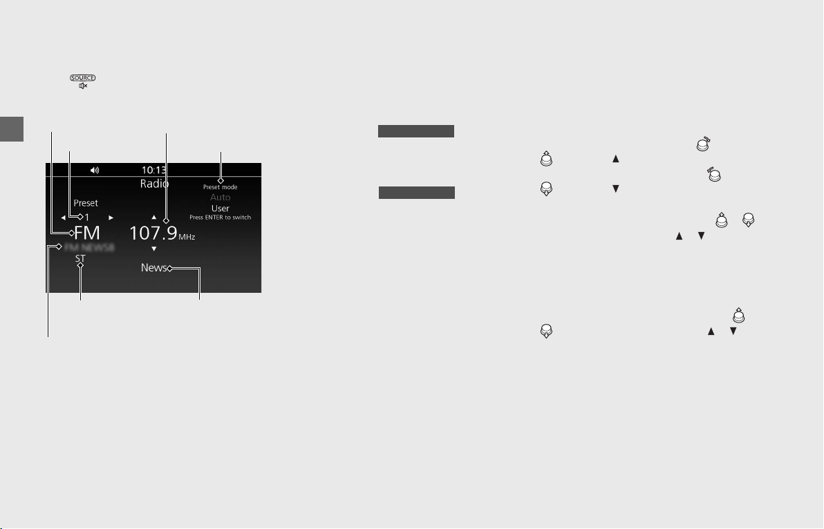
Operation Guide
92
Audio System (Continued)
Playing the FM/AM Radio
The audio system features FM/AM radio.
Press (Source/Private Mode) switch to
select to FM/AM radio. (P71)
Screen Information
[1] Band
[2] Preset number
[3] Current frequency
[4] Preset mode ([Auto]/[User])
[5] Station name
Displays that the station name of the
current station when available (FM radio
only).
[6] Program type
Displays the program type of the
current station when available (FM radio
only).
[7] ST (stereo) indicator
•Reception of a stereo signal is
indicated when the ST indicator
appears in the display. (Stereo
reception is available only for FM
stereo broadcasts.)
As FM stereo reception becomes
weaker, special circuits in the radio
gradually blend the sound toward
mono to maintain some sound quality,
even though the ST indicator remains
on.
❙
Select Station
You can tune the radio frequency one step
at a time.
The FM frequency moves in 200 kHz steps.
The AM frequency moves in 10 kHz steps.
To go up in frequency, rotate , move
or press on the 4-way key switch.
To go down in frequency, rotate , move
or press on the 4-way key switch.
Seek Mode:
Start the auto seek: when you move /
and hold or press and hold / on the 4-
way key switch for more than 1 second and
less than 1.5 seconds, the auto seek starts.
The audio system will seek until a broadcasting
station with a strong signal is detected.
Stop the auto seek: when you
move /
and hold or press and
hold /
on
the 4-way key switch for more than 1.5
seconds during the auto seeking, a beep
sounds once and return to the manual
tuning. The tuning stops at the frequency
when the switch is released.
If the beep setting is disabled, no beep
sounds.
To enable the beep sound:
(P77)
[1] Band
[2] Preset number
[3] Current frequency
[4] Preset mode
[7] ST indicator
(FM radio)
[5] Station name
(FM radio)
[6] Program type
(FM radio)
USA model only
USA model only
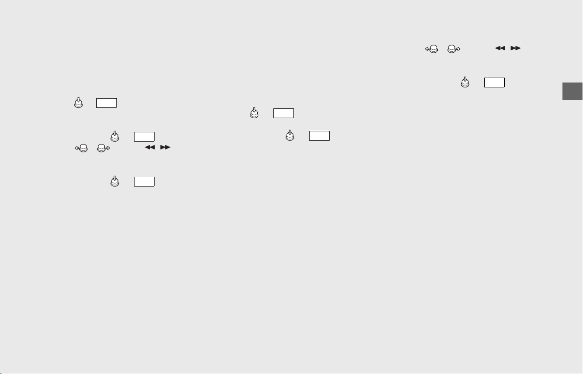
Operation Guide
93
❙
Preset Stations
To Store a Station Manually:
You can store the frequencies of your
favorite radio stations.
You can store 12 AM stations and 12 FM
stations in user preset mode.
!a Press or switch to select [User]
preset mode.
!b Tune in to a station you want to store.
!c Press and hold or switch.
!d Move / or press / on the
4-way key switch to select a preset
number (1 to 12).
!e Press and hold or switch.
To Store a Station Automatically:
If you are traveling far from home and can
no longer receive the stations you preset,
you can use the auto select function to find
stations in the local area.
You can store 12 AM stations and 12 FM
stations in auto preset mode.
!a Press or switch to select
[Auto] preset mode.
!b Press and hold or switch.
The audio system will seek and store
stations with strong signal
automatically.
uTo cancel the scan, select [Abort].
uIf you are in a remote area, the auto
select function may not find 12
stations.
uIf no available station is detected at
all, the stored preset stations are
kept.
uIf even one station is detected, all the
preset stations are overwritten.
To Select a Preset Station:
!aMove / or press / on the
4-way key switch to select a preset
station.
!bPress and hold or switch.
ENT
ENT
ENT
ENT
ENT
ENT
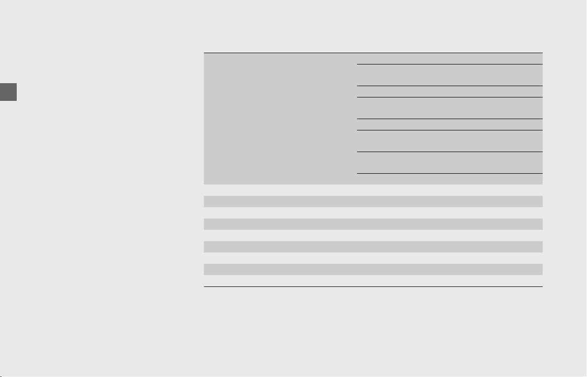
Operation Guide
94
Audio System (Continued)
Connecting your iPhone/iPod/USB
device
You can connect your iPhone/iPod/USB
device using a certified cable to the USB
connector or connect a USB flash drive, etc.
to the USB connector directly.
Make sure to use the factory USB cable that
came with your device.
• Some USB flash drives maybe
unsupported or incompatible and will
cause abnormal audio function, such as
skipping or playing delays.
•
Do not use hard disks, card readers, and
memory readers which may damage the
device and data. If you accidentally
connect the one of them, turn the ignition
switch OFF and remove it.
❙
Compatible Devices
iPhone, iPod and other devices compatible with your audio system are:
The audio system may not be compatible with the latest model and the latest OS version.
USB flash drive Standard USB 2.0/3.0
File systems FAT32 (recommendation),
FAT16, HFS+
Storage capacities From 256 MB to 64 GB
Maximum
hierarchies
8 hierarchies
Maximum folders 512 folders
Maximum files 65,524 files (same limitation
in one folder)
Maximum file/
folder name size
255 characters
Maximum file size 2 GB (in single file)
iPhone
®
5 or later iOS 10 or later
iPod touch
®
(5th generation or later) iOS 9 or later
iPod nano
®
(7th generation or later)
iPad
®
/iPad Air
®
/iPad Mini
®
(all model) Not supported
iPod classic
®
/iPod shuffle
®
(all model) Not supported
Hard disk drive Not supported
Card reader/Memory reader Not supported
CD/DVD/FD drive Not supported
USB hub Not supported

Operation Guide
95
❙
Audio Files on Device
MP3/WMA/WAV files in your device can be played on the following specifications.
• Do not edit other type of extension. Playing a device containing these kind of files can cause troubles such as the device or speakers
failure.
• Depending on the type of the character code used for the music information of audio files, the music information may not be displayed
correctly.
Windows Media is registered trademarks of Microsoft Corporation. in the U.S. and other countries.
MP3
Standard MPEG1 Audio Layer 3
File extension .mp3
Sample rate
(kHz)
32/44.1/48
Bit rates (kbps) 32/40/48/56/64/80/96/112/128/160/
192/224/256/320/VBR
Available tags ID3v2 (v2.2/v2.3/v2.4)
ID3v1 (v1.0/v1.1)
WMA
Standard Windows Media Audio Version 7/8/9
File extension .wma
Digital rights management (DRM) Not supported
Sample rate (kHz) 16/22.05/32/44.1/48
Bit rates (kbps) 5 to 320/VBR
Available tags ASF
WAV
Standard WAVE
File extension .wav
Sample rate (kHz) 16/22.05/32/44.1/48
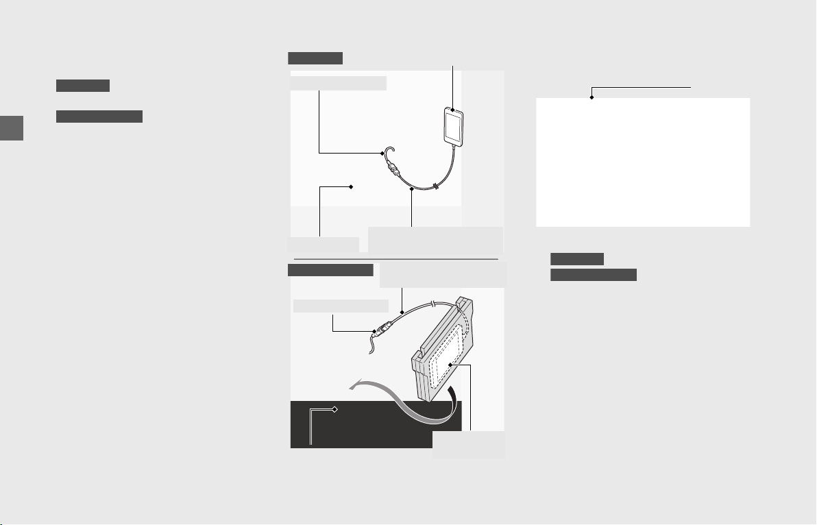
Operation Guide
96
Audio System (Continued)
❙
To Connect Your iPhone/iPod/USB Device
USB 1 connector
!a
Open the travel trunk. (P128)
Open the shelter case. (P131)
!b Connect your iPhone/iPod/USB device
using a certified cable to the USB 1
connector or connect a USB flash drive,
etc. to the USB 1 connector directly.
After connecting, the UBS icon appears
on the screen.
!cStore your device in the travel trunk
() or shelter case
().
!dClose the travel trunk or shelter case.
GL1800DA
Except GL1800DA
Shelter case
iPhone/iPod/USB device
Certified cable for the
device to be connected
USB 1 connector
Certified cable for the
device to be connected
USB 1 connector
iPhone/iPod/
USB device
GL1800DA
Except GL1800DA
Travel trunk
USB icon
GL1800DA
Except GL1800DA
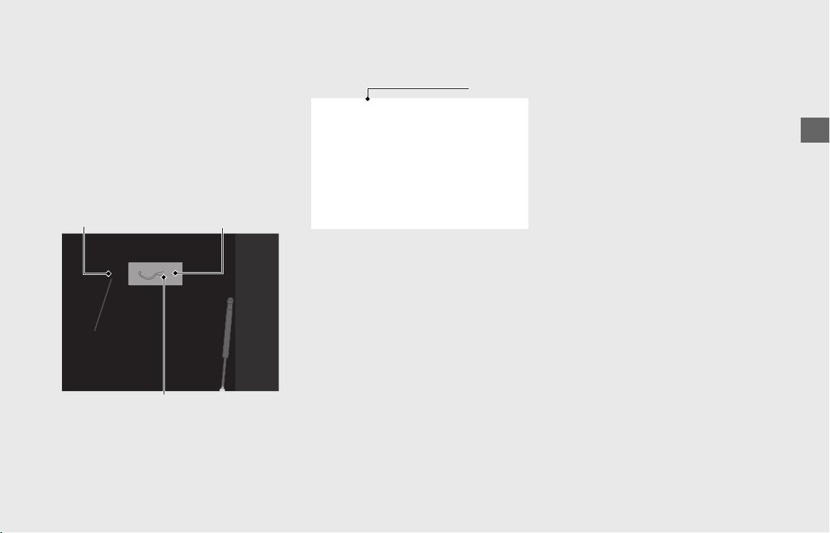
Operation Guide
97
USB 2 connector
• Apple CarPlay cannot be used with USB
connection via USB 2 connector.
!a Open the left saddlebag. (P128)
!b Release the USB 2 connector from the
connector cap.
!c Connect your iPhone/iPod/USB device
using a certified cable to the USB 2
connector or connect a USB flash drive,
etc. to the USB 2 connector directly.
After connecting, the UBS icon appears
on the screen.
!d Store your device in the left saddlebag.
!e Close the left saddlebag.
After using the USB connector, return the
USB connector to the connector cap.
❙
To Disconnect Your iPhone/iPod/USB
Device
You can disconnect your iPhone/iPod/USB
device at any time. Make sure to follow the
device’s instructions on how to disconnect
the device from the cable.
When you disconnect your device, the USB
icon will disappear from the screen.
• Do not leave your device in the vehicle
(travel trunk, shelter case or saddlebag
etc.). High heat will damage it.
• Read precaution statements on the
provided instructions of your device.
• Some USB flash drives (such as devices
with security lockout features, etc.) may
not be used or restricted to its function.
• We recommend backing up your data
before playing it.
• iPhone, iPod or some of USB devices can
be charged with the USB cable when the
ignition switch is in the ON or ACC
position. The charging time may be
longer than usual.
• We recommend covering your devices
with an audio pouch, or soft fabric or
cover to protect from damage.
• Be careful to not get the USB connector
wet.
• Do not connect with a hub.
• Do not connect incompatible devices.
• If the audio system does not recognize
the device, try reconnecting it a few
times or reboot the device.
Connector cap
USB 2 connector
Left saddlebag
USB icon
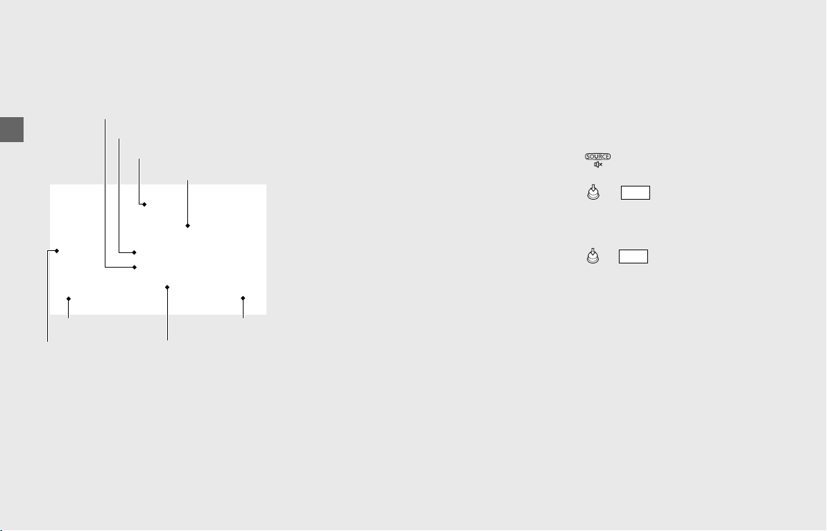
Operation Guide
98
Audio System (Continued)
Playing Audio
The audio system can play music stored on
a device connected via USB or Bluetooth
®
.
Screen Information
The information displayed on the screen
differs depending on the connected device
and the type of file being played back.
The system supports ID3 tag information. If
a track does not have an ID3 tag, the song
title or file name is displayed.
[1] Current audio mode
[2] Song title
[3] Artist name
[4] Album title (Folder name)
[5] Play time
[6] Progress bar
[7] Total time
[8] Album art (Displayed only when the
device is connected via USB and the
track contains artwork.)
❙
To Play a Track
!aConnect the device you want to play
from.
Bluetooth setting:
(P82)
Connecting your iPhone/iPod/USB
device:
(P96)
!bSelect the audio output device. (P71)
!cPress switch to select [USB], [iPod]
or [Bluetooth].
!dPress or switch to display the
playlist.
(P100)
!eSelect the supported audio file you
want to play. (P95)
!fPress or switch to play a track.
[2] Song title
[3] Artist name
[4] Album title
[7] Total time
[6] Progress bar
[8] Album art
[5] Play time
[1] Current audio mode
ENT
ENT
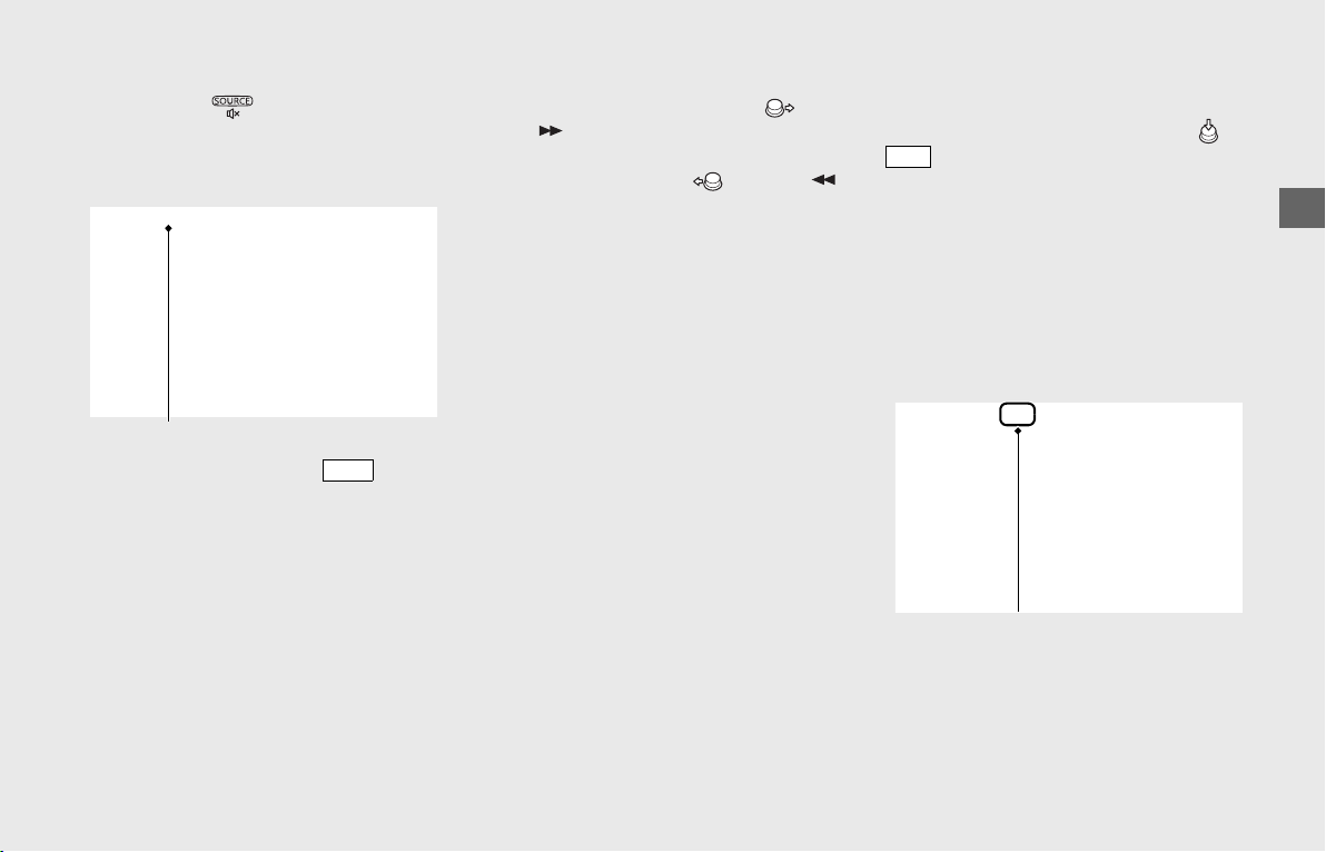
Operation Guide
99
continued
❙
To Pause a Track
Push and hold switch
to pause a track
and mute the volume.
uA diagonal line appears in the audio
output status icon on the screen.
To resume a track, operate lever
while volume is muted.
❙
To Change a Track
To skip to the next track, move or
press on the 4-way key switch.
To go back to the beginning of the current
or previous track, move or press
on the 4-way key switch.
❙
To Select the Play Mode
You can select repeat and random modes.
To switch the mode, press and hold or
switch.
The audio play mode status icon appears
on the upper part of the screen.
Cycles through the play modes as follows:
Normal play mode (blank) → Repeat all play
mode → Track repeat play mode →
Random play mode → Random & Repeat
all play mode → Random & track play
mode
Audio output status icon
VOL
ENT
Audio play mode status icon
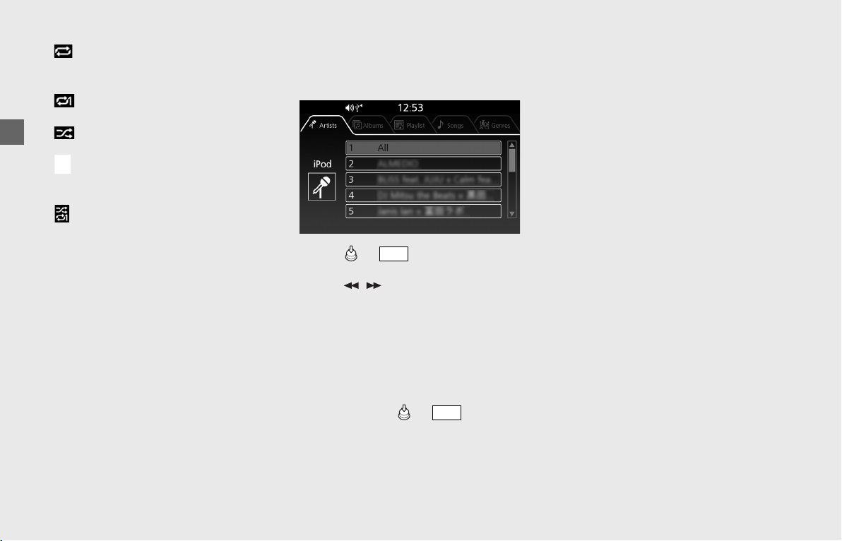
Operation Guide
100
Audio System (Continued)
• Repeat all play mode: Repeats all
tracks in the current playlist ([Artists],
[Albums] or [Folders], etc.).
• Track repeat play mode: Repeats the
current track.
• Random play mode: Plays tracks
randomly from the current playlist.
• Random & Repeat all play mode:
Plays tracks randomly and repeats all
tracks in the current playlist.
• Random & track play mode: Plays
tracks randomly and repeats the current
track.
❙
To Select a Track from the Playlist
You can select a track from various playlists
depending on the connected device.
!aPress or switch to display the
playlist.
!bPress / on the 4-way key switch
to change the playlist tab.
When iPod or Bluetooth
®
device is
connected: [Artists] → [Albums] →
[Playlist] → [Songs] → [Genres]
When USB device is connected:
[Folders] → [Songs]
!cSelect a desired item from the playlist,
and then press or switch.
• Available operating functions may differ
depending on the connected device and
the type of file being played back.
• If an iPhone is connected via Apple
CarPlay, the iPod/USB source is
unavailable and audio files on the phone
can only be played within Apple CarPlay.
ENT
ENT

Operation Guide
101
Apple CarPlay
™
If you connect an Apple CarPlay-
compatible iPhone to the system via USB,
you can use the multi-information display,
instead of the iPhone display, to make a
phone calls, listen to music, view maps
(navigation), and access messages.
• Only iPhone 5 or newer versions with iOS
10 or later are compatible with Apple
CarPlay.
• Park your vehicle in a safe place before
connecting your iPhone to Apple CarPlay
and when launching any compatible
apps.
• In no event shall Honda be liable for any
damages or troubles that occur in the
use of iPhone.
• If a mobile network communication is
unstable due to surrounding conditions
or signal strength conditions, Apple
CarPlay functions may not be available.
• To use Apple CarPlay, a headset
connection is necessary. If headset
connection is broken due to headset
battery depletion or communication
failure, Apple CarPlay cannot be used
until the connection is restored.
• You cannot operate Apple CarPlay by
the center panel switches/Interface dial
while the vehicle is in motion.
• Application and menu items displayed
on the screen may differ depending on
the connected device and iOS version.
• While connected to Apple CarPlay, calls
are only made through Apple CarPlay. If
you want to make a call with Bluetooth
®
handsfree calling, disconnect the USB
cable from your iPhone and connect
your iPhone via Bluetooth
®
.
To connect the paired device:
(P85)
• For details on countries and regions
where Apple CarPlay is available, as well
as information pertaining to function,
refer to the Apple homepage.
• Apple CarPlay cannot be used with USB
connection via USB 2 connector.
• Apple CarPlay is a trademark of Apple
Inc.
❙
Apple CarPlay Operating Requirements &
Limitations
Apple CarPlay requires a compatible iPhone
with an active cellular connection and data
plan. Your carrier’s rate plans will apply.
Changes in operating systems, hardware,
software, and other technology integral to
providing Apple CarPlay functionality, as
well as new or revised governmental
regulations, may result in a decrease or
cessation of Apple CarPlay functionality
and services.
Honda cannot and does not provide any
warranty or guarantee of future Apple
CarPlay performance or functionality.
It is possible to use 3rd party apps if they
are compatible with Apple CarPlay. Refer to
the Apple homepage for information on
compatible apps.
❙
Use of User and Vehicle Information
The use and handling of user and vehicle
information transmitted to/from your
iPhone by Apple CarPlay is governed by the
Apple iOS terms and conditions and
Apple’s Privacy Policy.
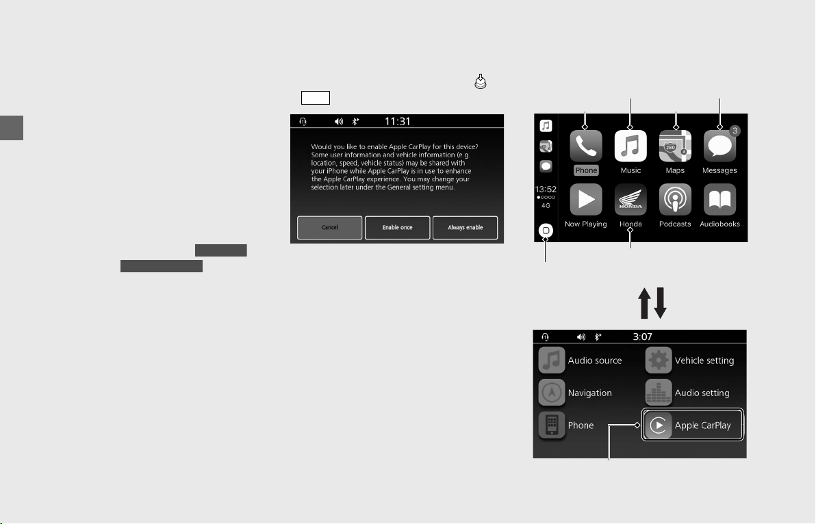
Operation Guide
102
Audio System (Continued)
❙
To Setup Apple CarPlay
Use of Apple CarPlay will result in the
transmission of certain user and vehicle
information (such as vehicle location,
speed, and status) to your iPhone to
enhance the Apple CarPlay experience. You
will need to consent to the sharing of this
information on the screen.
!a Enable the Apple CarPlay setting.
(P80)
!b Pair the headsets. (P88)
!c Connect your iPhone to the USB port
located in the travel trunk or
shelter case . (P96)
uWhen connecting your iPhone, if it is
recognized as iPod, disconnect the
USB cable once, enable the Apple
CarPlay
(P80), and then reconnect
the USB cable again.
!dWhen the disclaimer message appears
on the screen, select [Enable once] or
[Always enable], and then press or
switch.
[Enable once]: Allows only once.
(Prompt shows again next time.)
[Always enable]: Allows anytime.
(Prompt does not show again.)
[Cancel]: Does not allow this consent.
If select [Cancel] and do not allow this
consent, need to reconnect as iPod.
!eApple CarPlay menu screen appears.
❙
Apple CarPlay Menu
GL1800DA
Except GL1800DA
ENT
Go back to Apple CarPlay
menu screen
Phone
Go back to Home screen
Messages
Music
Maps
Home screen
Apple CarPlay menu screen
Go to Apple CarPlay menu screen
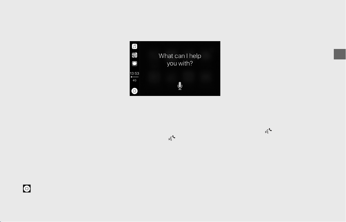
Operation Guide
103
Phone
Access the contact list, make phone calls,
or listen to voice mail.
Music
Play music stored on your iPhone.
Maps
Display Apple CarPlay map and use the
navigation function just as you would on
your iPhone.
u
Only one navigation system (pre-installed
navigation or Apple CarPlay) can give
directions at a time. When you are using
one system, directions to any prior
destination set on the other system will be
canceled, and the system you are currently
using will direct you to your destination.
Messages
Check and reply to text messages, or have
messages read to you.
HONDA
Go back to the Home screen.
Go back to the Apple CarPlay menu screen.
❙
Operating Apple CarPlay with Siri
To activate Siri, pairing with device such as
a headset must be paired. (P88)
To Activate Siri
!a Start Apple CarPlay.
(P102)
!b Unlock your iPhone and enable Siri.
uFor details, refer to the iPhone User
Guide, etc.
!c Press and hold switch on the left
handlebar.
!d Say a voice command through the
paired headset.
Siri may not be recognized correctly due to
the effect of wind noise during running or
external noise. In that case, try to change
the position of the microphone or to adjust
the windscreen height.
(P136)
Below Are Examples of Questions and
Commands for Siri
• Call dad at work.
• What song is this?
• How’s the weather tomorrow?
• Read my latest email.
• Find a table for four tonight in Chicago.
For more information, please visit
www.apple.com/ios/siri.
To Deactivate Siri
Press and hold switch on the left
handlebar.
Siri is a trademark of Apple Inc.

Operation Guide
104
Audio System (Continued)
Using Bluetooth
®
Handsfree Call-
ing
Bluetooth
®
handsfree calling allows you to
make and receive phone calls using your
vehicle's audio system, without handling
your mobile phone.
To use
the handsfree calling
, you need a
Bluetooth
®
compatible mobile phone and
Bluetooth
®
headsets.
• You cannot operate the handsfree
calling functions by the center panel
switches/Interface dial while the vehicle
is in motion.
•If Bluetooth
®
connection is unstable due
to surrounding conditions or radio wave
conditions, the handsfree calling
functions may not be available.
• While talking, you may be hard to hear
due to wind noise during running or
external noise. In that case, try to change
the position of the microphone or to
adjust the windscreen height.
(P136)
• The audio output will switch from
speaker to headset automatically when
making or receiving a phone call. (Even if
the headset is not connected).
❙
Preparation
!aConnect with the paired mobile phone.
(P82)
uWhen the phonebook import
function is enabled, the contents of
the mobile phone's phonebook and
call history are automatically
imported to the system.
The phonebook is updated after every
connection. Call history is updated
after every connection or call.
Phonebook Download:
(P90)
!bConnect the paired headsets (for rider
and passenger if necessary). (P88)
!cEnter the phone screen. (P23)
❙
Making a Call
You can make calls by inputting any phone
number or by using the imported
phonebook, call history or speed dial
entries.
To change the call mode, press / on
the 4-way key switch.
Changes the call modes as follows:
[Speed Dial]
(P105) → [Phonebook]
(P108) → [Call History] (P108) → [Dial
by Number] (P105)
To adjust the phone volume: (P71)
To enable/disable a call with
passenger's headset:
(P90)
• Certain manual functions are disabled
while the vehicle is in motion. You
cannot select a grayed-out option until
the vehicle is stopped.
• Only previously stored speed dial entries
and call history can be called while the
vehicle is in motion. However, if CarPlay
is running, you can make a call using the
Siri voice control system while the vehicle
is in motion.
(P103)
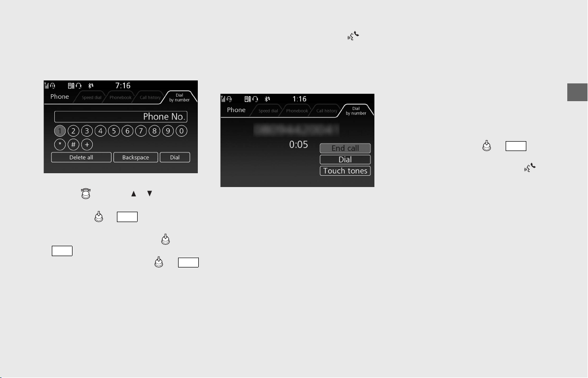
Operation Guide
105
To Make a Call Using a Phone Number
[Dial by number]
This function is disabled while the vehicle is
in motion.
!a Select [Dial by number].
!b Rotate or press / on the 4-
way key switch to enter a number, and
then press or switch to set the
number.
!c Select [Dial], and then press or
switch to make a call.
uTo cancel the call, press or
switch.
!d To end the call, press and hold
(Voice control) switch on the left
handlebar.
u
The same action can be done by
selecting [End call] on the screen.
To Make a Call Using a Speed Dial Entry
[Speed dial]
You can make a call using the speed dial
while the vehicle is in motion.
To make a call using the speed dial, you
need to store the speed dial number in
advance.
(P106)
Up to 20 speed dial numbers can be stored.
!aSelect [Speed dial].
!bSelect the phone number you want to
call, and then press or switch.
Dialing starts automatically.
!cTo end the call, press and hold
(Voice control) switch on the left
handlebar.
u
The same action can be done by
selecting [End call] on the screen.
ENT
ENT
ENT
ENT
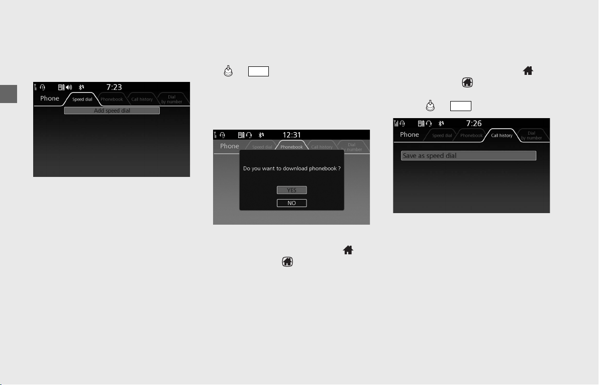
Operation Guide
106
Audio System (Continued)
To Store a Phone Number in the Speed
Dial List
Speed dial numbers can be stored in three
ways.
From [Speed Dial]:
!aSelect [Speed dial].
!bSelect [Add speed dial], and then press
or switch.
!cThe phonebook appears.
uIf the phonebook import function is
disabled, select [YES] to import the
phonebook manually.
!dSelect the phone number you want to
store, and then press and hold
(Home) button/ (Home) switch.
The phone number will be stored in the
speed dial list.
From [Call history]/[Phonebook]:
!aSelect [Call history] or [Phonebook].
!bSelect the phone number you want to
store, and then press and hold
(Home) button/ (Home) switch.
!cSelect [Save as Speed Dial], and then
press or switch.
The phone number will be stored in the
speed dial list.
ENT
ENT
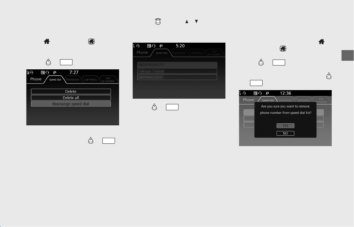
Operation Guide
107
To Rearrange the Order of the Speed
Dial List
!a Select [Speed dial], and then press and
hold (Home) button/ (Home)
switch.
!b Select [Rearrange speed dial], and then
press or switch.
!c Select the phone number you want to
arrange, and then press or
switch.
!d Rotate or press / on the 4-
way key switch to change the order of
the speed dial list.
!e Press or switch to set your
selection.
To Delete a Stored Speed Dial Number
!aSelect [Speed dial].
!bSelect the phone number you want to
delete, and then press and hold
(Home) button/ (Home) switch.
!cSelect [Delete] or [Delete all], and then
press or switch.
!dA confirmation message appears on the
screen. Select [YES], and then press
or switch.
ENT
ENT
ENT
ENT
ENT
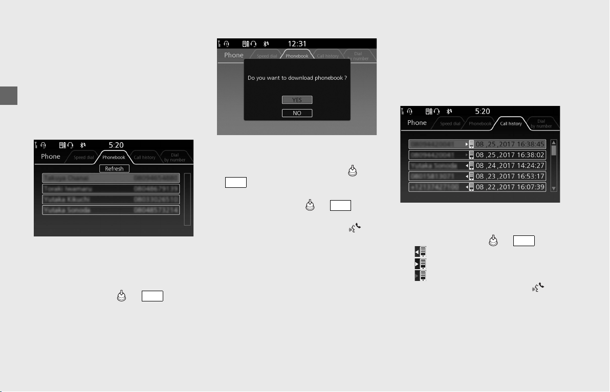
Operation Guide
108
Audio System (Continued)
To Make a Call Using the Imported
Phonebook [Phonebook]
This function is disabled while the vehicle is
in motion.
When the phonebook import function is
enabled, the contents of the phone's
phonebook is automatically imported to
the system.
Phonebook Download:
(P90)
If the phonebook import function is
disabled, a popup message will be
displayed on the screen.
To import the phonebook manually, select
[YES], and then press or switch.
!aSelect [Phonebook].
!bThe phonebook is stored alphabetically.
Select a name, and then press or
switch.
!cSelect the phone number you want to
call, and then press or switch.
Dialing starts automatically.
!dTo end the call, press and hold
(Voice control) switch on the left
handlebar.
u
The same action can be done by
selecting [End call] on the screen.
To Make a Call Using the Call History
[Call history]
You can make a call using the call history
while the vehicle is in motion.
Call history displays the last 30 dialed,
received, or missed calls.
!aSelect [Call history].
!bSelect the phone number you want to
call, and then press or switch.
• : Dialed call
• : Received call
• (red): Missed call
!cTo end the call, press and hold
(Voice control) switch on the left
handlebar.
u
The same action can be done by
selecting [End call] on the screen.
ENT
ENT
ENT
ENT
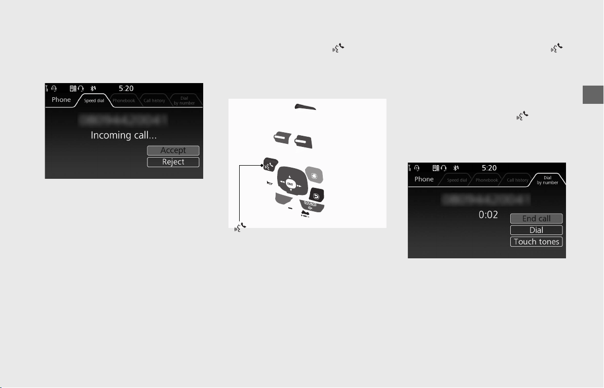
Operation Guide
109
❙
Receiving a Call
When there is an incoming call, an audible
notification sounds and the Incoming Call
screen appears.
Ring Tone
If the connected mobile phone supports “in
band ring tone”, the ring tone stored on
the phone sounds automatically while
receiving a call automatically.
If “in band ring tone” is not supported, the
ring tone stored in the audio system
sounds.
To Receive a Call
When a call comes in, press switch on
the left handlebar to receive the call.
u
The same action can be done by selecting
[Accept] on the screen.
To adjust the phone volume: (P71)
To enable/disable a call with
passenger's headset:
(P90)
To Reject a Call
When a call comes in, press and hold
switch on the left handlebar to reject a call.
u
The same action can be done by selecting
[Reject] on the screen.
To End a Call
While talking, press and hold switch on
the left handlebar to end the call.
u
The same action can be done by selecting
[End call] on the screen.
switch
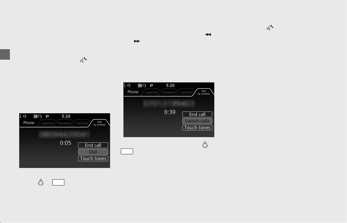
Operation Guide
110
Audio System (Continued)
❙
Making Multiple Calls
You can handle multiple calls at the same
time if the connected mobile phone
supports the call waiting function.
To Receive a Second Call
When a call comes in, press switch on
the left handlebar to receive the call.
If the recipient answers, the first call is put
on hold.
u
The same action can be done by selecting
[Accept] on the screen.
To Make a Second Call
!a During a call, select [Dial], and then
press or switch.
!b Select a phone number from [Speed
dial], [Phonebook] or [Call history] or
enter a phone number in [Dial by
number].
uTo change the call mode, press /
on the 4-way key switch.
!cThe second outgoing call will start. If
the recipient answers, the first call is put
on hold.
To Switch Between Multiple Calls
Select [Switch calls], and then press or
switch.
To End a Call in Progress
!aPress and hold switch on the left
handlebar to end the second call.
u
The same action can be done by
selecting [End call] on the screen
.
!bThe system will return to the first call on
hold.
ENT
ENT
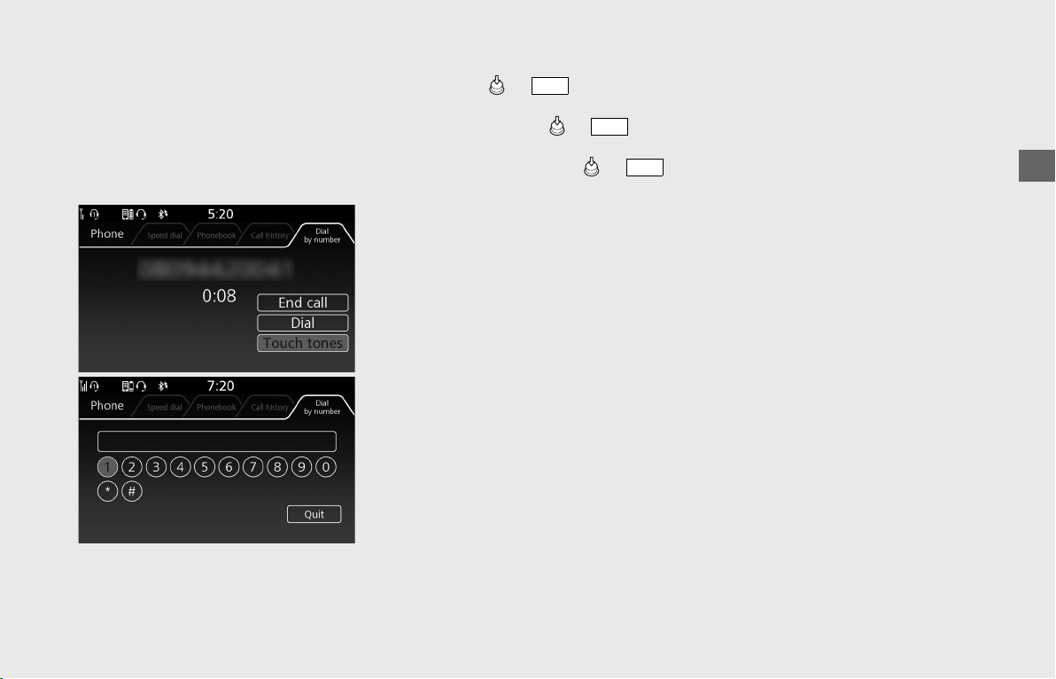
Operation Guide
111
❙
Sending DTMF tones during a call
You can send DTMF (Dual Tone Multi
Frequency) tones during a call.
This is useful when you call a menu-driven
phone system.
This function is disabled while the vehicle is
in motion.
!a During a call, select [Touch tones], and
then press or switch.
!b To send a DTMF tone, select a number
key, and then press or switch.
u
T
o return to the previous screen,
select [Quit] and press or
switch.
ENT
ENT
ENT
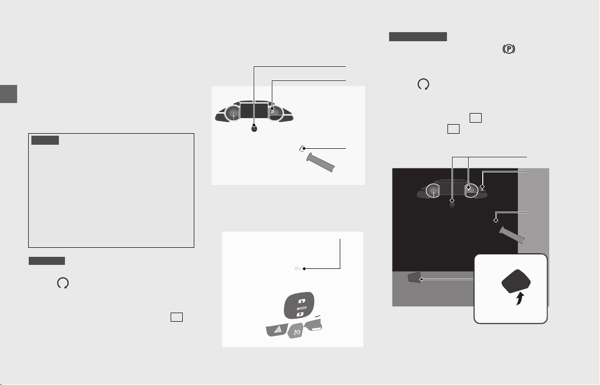
Operation Guide
112
Starting the Engine
Start your engine using the following
procedure, regardless of whether the
engine is cold or warm.
This vehicle is equipped with a Honda
SMART Key system. Always keep Honda
SMART Key on you when you ride the
vehicle.
(P56)
!a Make sure the engine stop switch is in
the (Run) position.
!b Unlock the steering.
(P55)
!c Turn the ignition switch to ON. (P49)
!d Shift the transmission to Neutral (
indicator comes on). Alternatively, pull
in the clutch lever to start your vehicle
with the transmission in gear so long as
the side stand is raised.
!ePress the start button with the throttle
completely closed.
!aCheck the parking brake ( parking
brake indicator comes on).
!bMake sure the engine stop switch is in
the (Run) position.
!cUnlock the steering. (P55)
!dTurn the ignition switch to ON. (P49)
u Make sure the indicator comes
on. If the indicator does not come
on.
(P115)
NOTICE
• If the starter operates but the engine does not start,
turn the ignition switch to OFF and wait 10 seconds
before trying to start the engine again to recover
battery voltage.
• Extended fast idling and revving the engine can
damage the engine, and the exhaust system.
• Snapping the throttle or fast idling for more than
about 5 minutes may cause exhaust pipe
discoloration.
• The engine will not start if the throttle is fully open.
GL1800/B
N
!b!c
!d
!a
!e
GL1800BD/D/DA
N
N
!a
!c!d
!a
!b

Operation Guide
113
!e Press the start button with the throttle
completely closed.
!f Make sure the parking brake lever is
released before riding.
If the engine does not start:
!a Open the throttle fully an
start button once.
!b Repeat the normal starting procedure.
!c If the engine starts, open the thrott
slightly if idling is unstable.
!d If the engine does not st
seconds before trying steps !a & !b
again.
❙
If Engine Will Not Start
(P177)
Quick Engine Starting
You can also start the engine by the
following procedure.
!a Make sure the status of the Honda
SMART Key is active
(P56) and enter
the operating range. (P57)
!b While applying the brake lever or pedal
firmly, press and hold the start button
until engine starts.
u The steering lock is automatically
unlocked at the same time.
u The quick engine starting will not
operate if the transmission is in gear.
The process will stop with the
ignition switch ON.
Start the engine with normal starting
procedure.
(P112)
u The engine will not start unless you
perform the quick starting with
correct conditions such as applying
the brake. The process will stop with
the ignition switch ON.
Start the engine with normal starting
procedure.
(P112)
When You Stop the Engine
!aTo stop the engine, put the g
Neutral ( indicator comes on).
!bTurn the ignition switch to OFF.
u If you turn the
ignition switch to OFF when the
vehicle in gear, the engine will shut
off with the clutch disengaged.
!c Set the parking brake
when you park the vehicle.
(P60)
!e
N
GL1800BD/D/DA
GL1800BD/D/DA
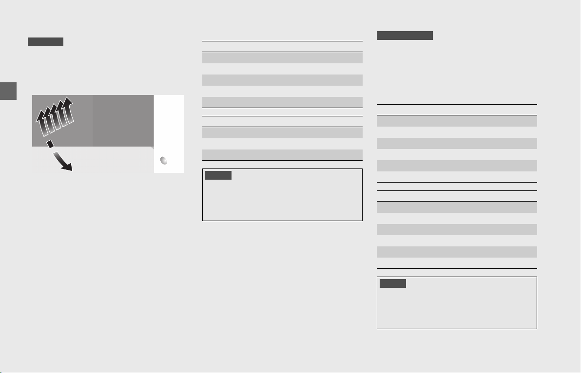
Operation Guide
114
Shifting Gears
Your vehicle transmission has 6 forward
gears in a one-down, five-up shift pattern.
If you put the vehicle in gear with the side
stand down, the engine will shut off.
❙
Recommended Shift Points
Your vehicle is equipped with an
automatically controlled 7-speed
transmission. It can be shifted automatically
(by AT MODE) or manually (by MT MODE).
❙
Recommended Shift Points
GL1800/B
1
6
2
5
4
3
N
Shifting Up
From 1st to 2nd 12 mph (20 km/h)
From 2nd to 3rd 19 mph (30 km/h)
From 3rd to 4th 25 mph (40 km/h)
From 4th to 5th 31 mph (50 km/h)
From 5th to 6th 37 mph (60 km/h)
Shifting Down
From 6th to 5th 28 mph (45 km/h)
From 5th to 4th 22 mph (35 km/h)
From 4th to 3rd 16 mph (25 km/h)
NOTICE
Improper shifting can damage the engine,
transmission, and drive train. Also, coasting or towing
the vehicle for long distances with the engine off can
damage the transmission.
Shifting Up
From 1st to 2nd 15 mph (24 km/h)
From 2nd to 3rd 20 mph (32 km/h)
From 3rd to 4th 27 mph (43 km/h)
From 4th to 5th 35 mph (56 km/h)
From 5th to 6th 45 mph (72 km/h)
From 6th to 7th 55 mph (88 km/h)
Shifting Down
From 7th to 6th 45 mph (72 km/h)
From 6th to 5th 35 mph (56 km/h)
From 5th to 4th 25 mph (40 km/h)
From 4th to 3rd 18 mph (29 km/h)
From 3rd to 2nd 13 mph (21 km/h)
From 2nd to 1st 10 mph (16 km/h)
NOTICE
Improper shifting can damage the engine,
transmission, and drive train. Also, coasting or towing
the vehicle for long distances with the engine off can
damage the transmission.
GL1800BD/D/DA
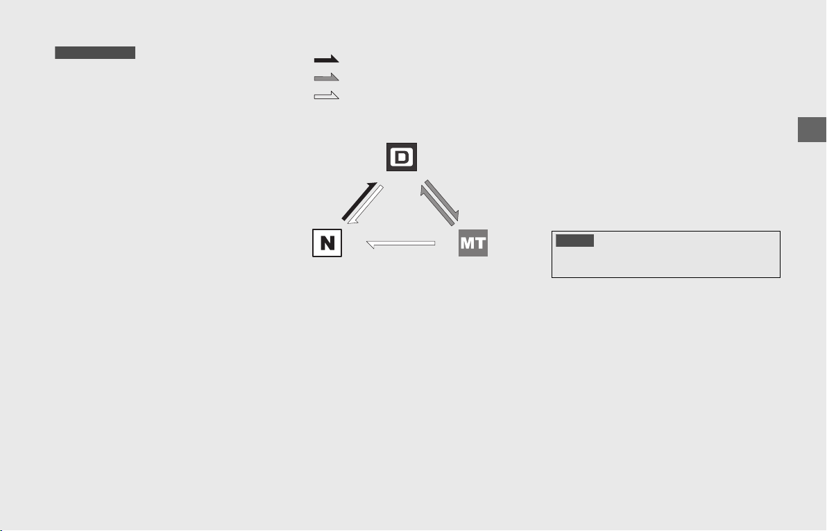
Operation Guide
115
continued
Dual Clutch Transmission
In order to respond to rider demands in a
broad range of situations, the transmission
is equipped with two operating modes, AT
MODE (D) (automatic shift for regular
operation); and MT MODE (for 7-speed
manual operation), which delivers the same
shift feel as a manual transmission.
u Always use the recommended tires to
ensure correct Dual Clutch Transmission
operation.
The Dual Clutch Transmission system runs a
self check immediately after starting the
engine.
“-” appears in the gear position indicator
for a few seconds, then goes out.
While “-” appears, you cannot shift into
gear.
Neutral (N):
Neutral is selected automatically
when you turn the ignition switch to ON.
If neutral is not selected when you
turn the ignition switch to ON:
u Turn the ignition OFF and ON again.
You may hear (click) noises when the
transmission shifts to Neutral (N). This is
normal.
u If the Neutral (N) is still not selected after
turning the ignition switch on, start the
engine while applying the brake with
side stand raised. If Neutral (N) is still not
selected.
(P185)
When you can change between
Neutral (N) and AT MODE (D):
u Vehicle is stopped and the engine is
idling.
u Throttle is completely closed. It is not
possible to change from Neutral (N) to
AT mode (D) while the throttle is applied.
u You cannot change between Neutral (N)
and AT MODE (D) while the wheels are
rotating.
u Side stand is raised.
AT MODE (D): In this mode the gears are
shifted automatically according to your
riding conditions.
And also using the shift up switch (+) or
shift down switch (-), you can temporarily
shift up or down. These switches are
convenient when you want to temporarily
down-shift in front of a curve, etc.
(P116)
MT MODE: You can choose between 7
gears in this mode.
GL1800BD/D/DA
Press the N side of the N-D switch
Press the D side of the N-D switch
Press the A/M switch
AT MODE (D)
MT MODE
NOTICE
To prevent clutch damage, do not use the throttle to
keep the vehicle stopped uphill.
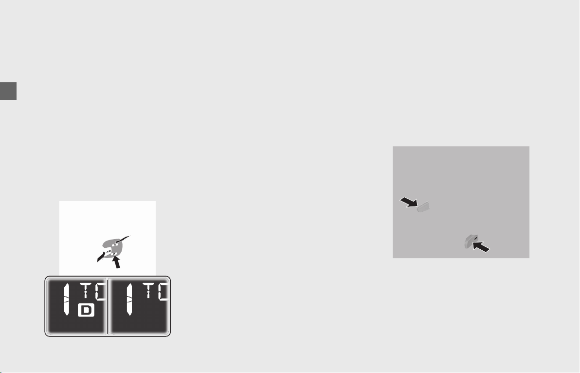
Operation Guide
116
Shifting Gears (Continued)
Changing between Neutral and AT
MODE/MT MODE
Changing from Neutral (N) to AT MODE (D)
Press the D side of the N-D switch (!a).
The D (AT MODE) indicator comes on, ”1”
is shown in the gear position indicator and
first gear is selected.
Changing from AT MODE or MT MODE
to Neutral (N)
Press the N side of the N-D switch (!b).
Changing between AT MODE and MT
MODE
Press the A/M switch (!c).
The D (AT MODE) indicator goes out while
MT MODE is selected (!d).
Riding in MT MODE
Shift up and down with the shift up switch
(+) and shift down switch (-).
The selected gear is shown on the gear
position indicator.
u If the MT MODE is selected, the
transmission does not shift up
automatically. Do not allow the engine
revs to go into the red zone.
u The transmission automatically shifts
down when you slow down, even in MT
MODE.
u You will start from 1st gear even if MT
MODE is selected.
Downshifting Blipping Control
In MT MODE, this system controls down
shifting with the throttle completely closed
by increasing engine revs automatically to
match the gear ratio.
u This system may not increase engine revs
in some running conditions.
Gear shift operation
Shifting Up:
Press the shift up switch (+) (!e).
Shifting Down:
Press the shift down switch (-) (!f).
You cannot continue shifting gear by
keeping the shift switch pressed.
To continue shifting gear release the switch
and press it again.
Shift Limit
You cannot downshift if the engine will
exceed the rev limit.
!a
!a
!b
!c
!d
!e
!f
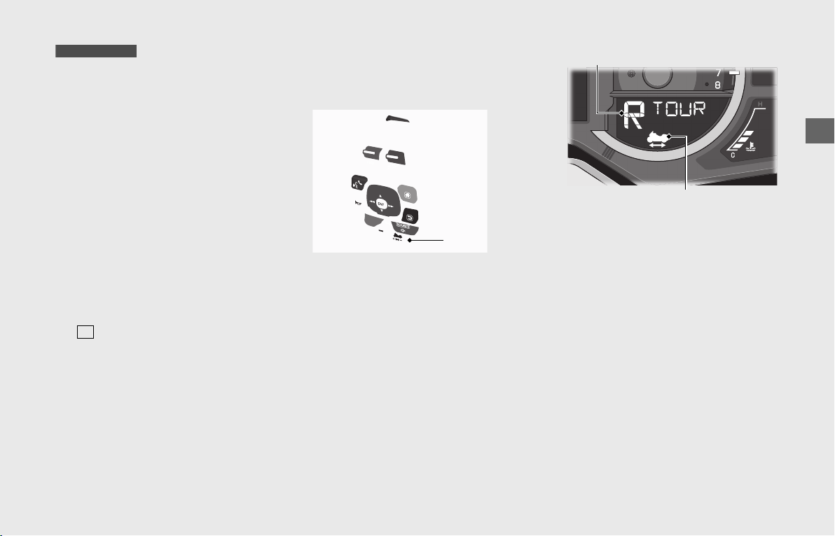
Operation Guide
117
Walking Speed Mode
The Walking Speed mode assists the rider
with getting the vehicle into or out of tight
areas by maneuvering the vehicle at slow
speed.
u Operate the vehicle’s engine only in a
well-ventilated area.
Make sure there are no obstacles or people
in the area. Avoid steep or uneven surfaces.
Carrying a passenger while in Walking
Speed mode is not recommended because
it makes balance and control more difficult
to maintain.
!a Sit astride the vehicle, in your normal
riding position, with both feet on the
ground.
!b Make sure the transmission is in neutral
( indicator comes on) and the side
stand is up.
!c Start the engine.
(P112)
!d Press the Walking Speed mode switch
while applying the brake lever or pedal.
The Walking Speed mode indicator is
displayed.
GL1800BD/D/DA
N
Walking Speed
mode switch
Walking Speed mode indicator
Gear position indicator
continued
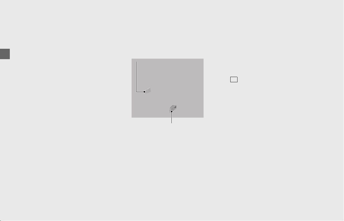
Operation Guide
118
Walking Speed Mode (Continued)
!e To move the vehicle backward, press
and hold the shift down switch (-), and
then release the brakes.
To move the vehicle forward, press and
hold the shift up switch (+), and then
release the brakes.
u The vehicle will move forward/
backward as long as you hold the
switch down.
u When the shift up switch (+)
(forward) is pressed, “F” is displayed
on the gear position indicator.
When the shift down switch (-)
(backward) is pressed, “R” is
displayed on the gear position
indicator.
u It may take a few seconds before the
vehicle starts to move.
u When operating the vehicle in
Walking Speed mode, be sure to sit
on the vehicle in your normal riding
position.
u When the engine is stopped in
Walking Speed mode, the clutch will
disengage. This will cause the vehicle
to abruptly lose traction.
u While in Walking Speed mode, do
not press the engine stop switch
except in an emergency. This will
cause the vehicle to abruptly lose
traction.
Guide the vehicle cautiously, using your
legs to maintain balance.
Use extreme care to maintain balance
while in Walking Speed mode on loose
surfaces (sand, dirt, gravel) or slick
pavement.
!fTo stop the vehicle, apply the brake
lever or pedal.
!gTo end Walking Speed mode, apply the
brake lever or pedal. After the vehicle
has stopped, press the Walking Speed
mode switch while operating the brake
lever or pedal, or press the N side of the
N-D switch. Make sure the Walking
Speed mode indicator turns off and the
indicator comes on.
Shift up switch (+)
Shift down switch (-)
N
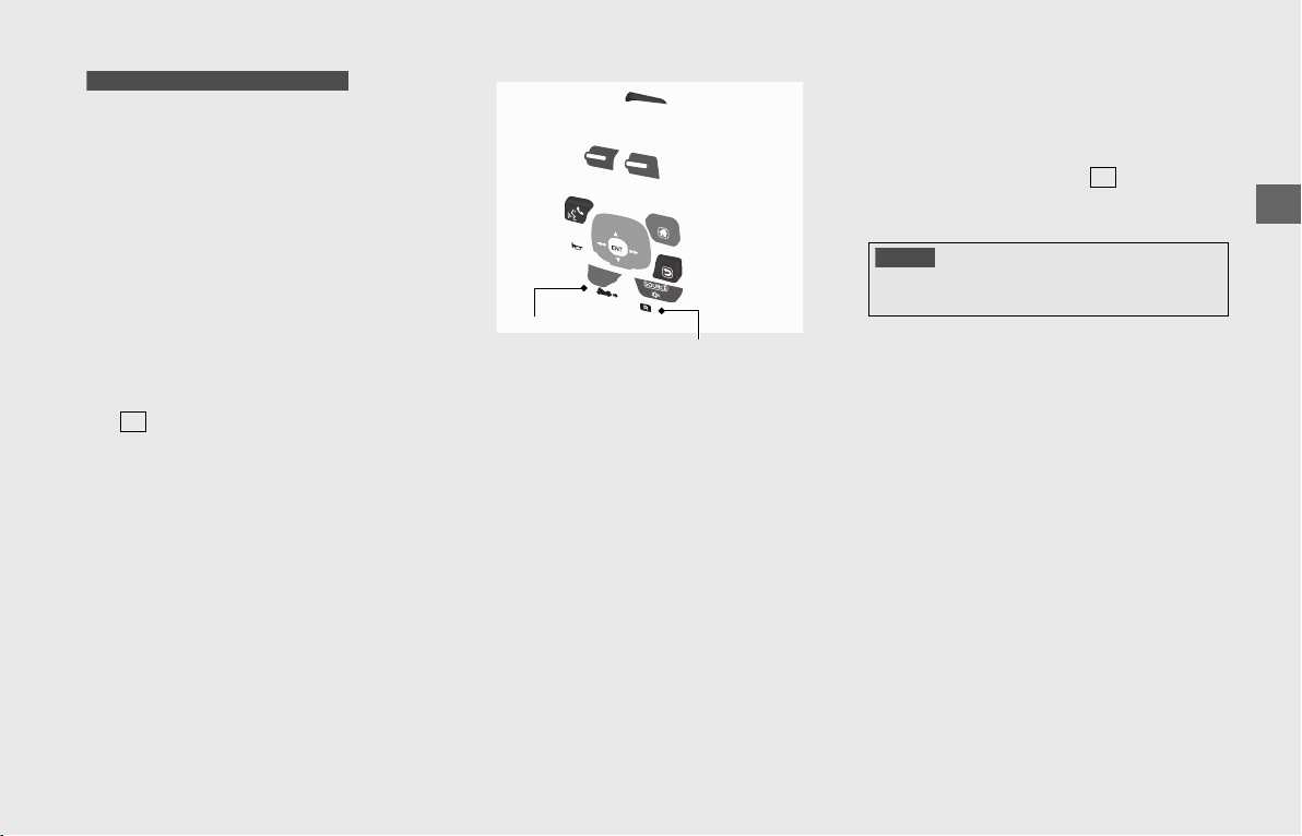
Operation Guide
119
Moving in Reverse
Your vehicle’s reverse system allows you to
back out of a parking space at slow speed.
Make sure there are no obstacles or people
in the direction of travel. Avoid steep or
uneven surfaces. Carrying a passenger
while reversing is not recommended
because it makes balance and control more
difficult to maintain.
!a Sit astride the vehicle, in your normal
riding position, with both feet on the
ground.
!b Make sure the transmission is in neutral
( indicator comes on) and the side
stand is up.
!c Start the engine.
(P112)
!d Press the Reverse mode switch to turn
on the reverse mode.
u If the engine is not running, the
reverse system cannot be activated.
!e When you are ready to back up, press
and hold the Reverse button.
The vehicle will move in reverse as long
as you hold the button down. (“R” is
displayed on the gear position
indicator.)
To prevent battery discharge, do not
press the Reverse button for more than
1 minute.
!f Guide the vehicle backward cautiously,
using your legs to maintain balance.
Use extreme care to maintain balance
while reversing on loose surfaces (sand,
dirt, gravel) or slick pavement.
!gRelease the Reverse button, and the
vehicle will stop.
!hAfter your vehicle has stopped, press
the Reverse mode switch to turn off the
system. Make sure the indicator
comes on.
Reverse System Overload
The Reverse mode is designed to move the
vehicle at a constant slow speed.
If the vehicle begins moving slower or
faster than this speed because of obstacles
or a steep pavement angle, press the
Reverse mode switch to turn off the system
and carefully roll the vehicle to a more level,
unobstructed surface, and then start again.
GL1800 and GL1800B Canada model
N
Reverse
button
Reverse mode switch
NOTICE
To avoid damaging the reverse system, do not engage
or disengage reverse when the vehicle is moving.
N
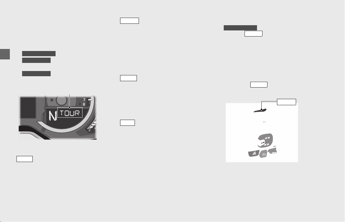
Operation Guide
120
Riding Mode
You can change the riding mode.
The following parameters change
according to each riding mode.
• Engine output characteristic
• Brake feel
• DCT characteristic
• Toque Control operating
level
• Suspension damping
characteristic
The following riding modes are available:
mode:
TOUR mode provides an engine and
braking feel and suspension damping
characteristics optimized for comfortable
riding in situations such as long distance
touring.
mode:
SPORT mode has a quicker and more
powerful engine feel, harder braking feel,
and harder suspension damping
characteristics than with TOUR mode.
For models equipped with DCT, shifting
characteristics are oriented to maintain
middle and high engine speeds.
mode:
ECON mode has a gentler engine feel than
with TOUR mode.
For models equipped with DCT, shifting
characteristics are oriented to maintain low
and middle engine speeds.
mode:
RAIN mode has a gentler engine feel and
softer suspension damping characteristics
than with TOUR mode.
For models equipped with DCT, shifting
characteristics are gentler than those with
TOUR mode.
Selecting the Riding Mode
Press the button while the throttle
is fully closed.
u The riding mode indicator blinks until the
riding mode is changed.
u The riding mode does not change until
the throttle is fully closed.
u Each time the ignition switch is turned to
ON, the riding mode will automatically
be set to mode.
GL1800BD/D/DA
GL1800/D/DA
GL1800/D/DA
Riding mode indicator
TOUR
SPORT
ECON
RAIN
GL1800BD/D/DA
MODE
TOUR
button
MODE
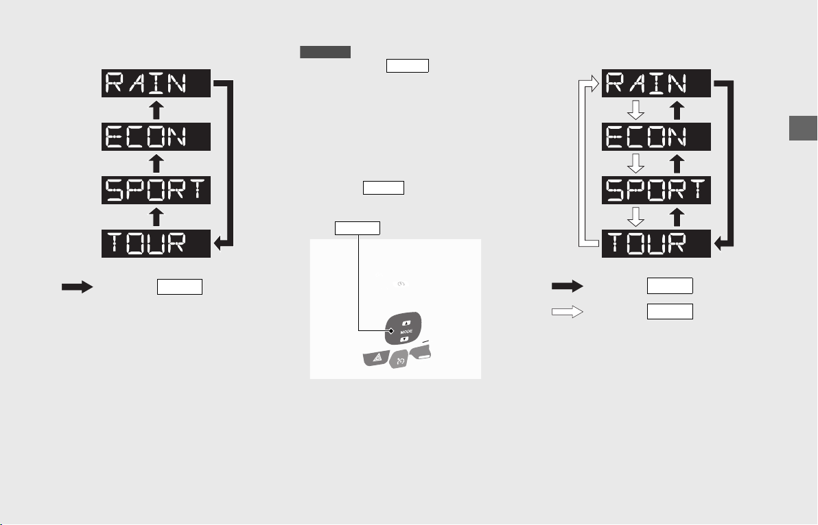
Operation Guide
121
Press one of the buttons ( or )
while the throttle is fully closed.
u The riding mode indicator blinks until the
riding mode is changed.
u The riding mode does not change until
the throttle is fully closed.
u Each time the ignition switch is turned to
ON, the riding mode will automatically
be set to mode.
If all the segments of the riding mode
indicator are displayed, see your dealer for
servicing.
: Press the button
MODE
GL1800/B
MODE
TOUR
buttons
MODE
: Press the () button
MODE
: Press the () button
MODE

Operation Guide
122
Honda Selectable Torque Control (Torque Control)
Toque Control will limit the amount of
torque applied to the rear wheel when the
system detects the rear wheel spin during
acceleration.
Toque Control can be turned on or off in
the multi-information display.
(P31)
u Torque Control mode (on/off) cannot be
changed while riding.
Stop the vehicle first and select the
Torque Control mode (on/off) in the
multi-information display.
u Each time the ignition switch is turned
ON, the Torque Control is automatically
turned to on.
u When the Riding mode is changed, the
Torque Control characteristic also
changes according to each mode.
GL1800/D/DA
HSTC (Honda Selectable
Torque Control)
Torque Control indicator
Torque Control OFF indicator
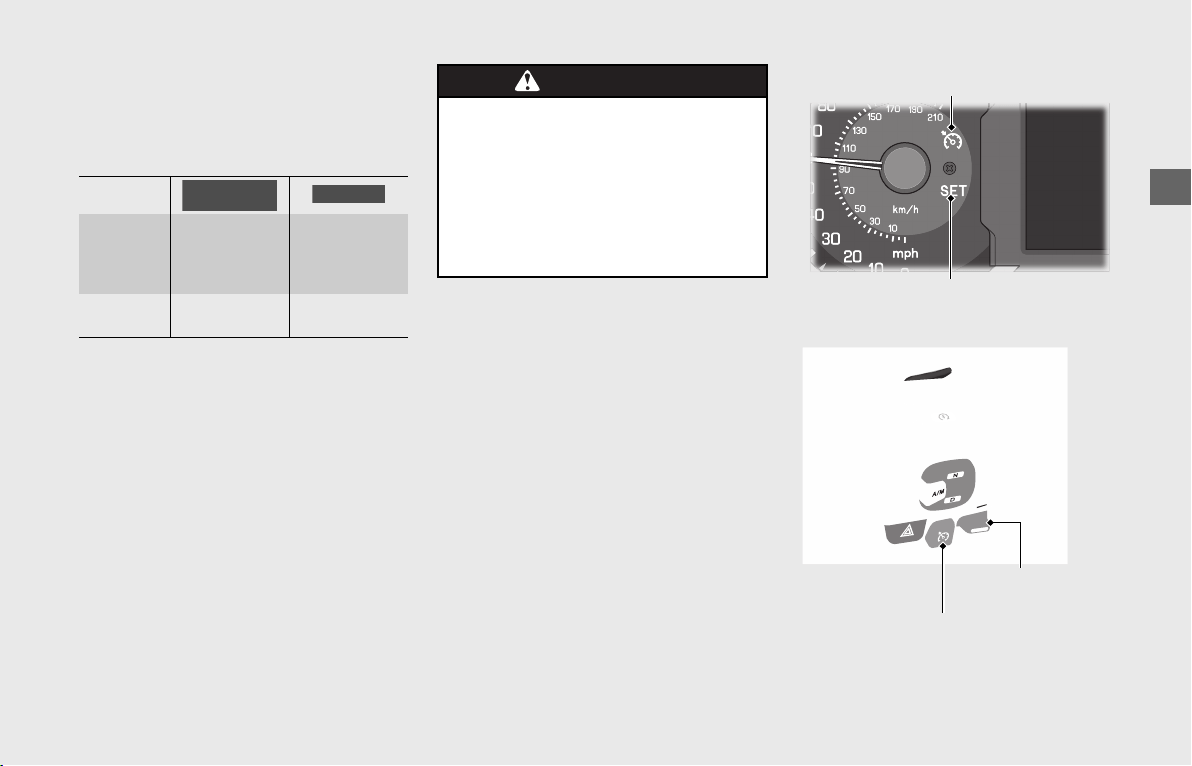
Operation Guide
123
Cruise Control
The cruise control system allows you to
maintain a steady speed within specified
range.
The available speed setting range and
operating gear are listed below:
When cruise control is on, your speed will
still vary slightly, particularly going up and
down hills.
Cruise control is intended for use only on
straight, uncongested highways. Do not
use cruise control on city streets, winding
roads, during bad weather, or at any other
time when you need total control of the
throttle.
To Set Cruise Control
!a Make sure the traveling speed and
operating gear are conformed to
requirement of the system.
Any speed other than available range
will not be memorized.
!b Press the cruise control main switch.
(The CRUISE MAIN indicator will come
on.)
!c Accelerate to the desired speed.
!d Push the cruise control lever to [SET/-]
side. (The CRUISE SET indicator will
come on.)
Your current traveling speed is
memorized.
Available
speed
setting
range
20 - 100 mph
(30 - 160 km/h)
30 - 100 mph
(50 - 160 km/h)
Operating
gear
From 3rd to
7th gear
From 3rd to
6th gear
GL1800BD/D/
DA
GL1800/B
WARNINGWARNING
Improper use of the cruise control
can lead to a crash in which you
could be seriously hurt or killed.
Use the cruise control only when
traveling on open highways in good
weather.
CRUISE MAIN indicator
CRUISE SET indicator
Cruise control main switch
Cruise control
lever

Operation Guide
124
Cruise Control (Continued)
To Change the Set Speed
To Fine Tune the Set Speed
Display the cruise control set speed on the
INFO 1 display. (P34)
• To increase the set speed: tap the cruise
control lever to [RES/+] side.
• To decrease the set speed: tap the cruise
control lever to [SET/-] side.
The set speed is displayed in the INFO 1
display.
Each quick tap (brief push and release) on
either side will change your speed by 1 mph
or 1 km/h (depending on mileage meter set
unit).
Any speed other than possible setting
range will not be indicated (stops at the
upper or lower limit speed).
To Change the Set Speed Continuously
• To increase the set speed: push and hold
the cruise control lever to [RES/+] side.
The system will accelerate your vehicle
automatically. When you reach the
desired speed, release the cruise control
lever.
If the cruise control lever is pushed and
held to [RES/+] side continuously, the set
speed indicated in the INFO 1 display
stops at the upper limit of the possible
setting range.
• To decrease speed: push and hold the
cruise control lever to [SET/-] side. The
system will automatically slow your
vehicle. When you reach the desired
speed, release the cruise control lever.
If the cruise control lever is pushed and
held to [SET/-] side continuously, the set
speed indicated in the INFO 1 display
stops at the lower limit of the possible
setting range.
To Manually Increase the Set Speed
!aUse the throttle to accelerate until you
reach the desired speed.
!bPush and release the cruise control lever
to [SET/-] side.
To Manually Increase Vehicle Speed
!aUse the throttle in the normal manner
to accelerate.
!bTo return to the set speed, close the
throttle and coast without applying the
brakes. The cruise system will maintain
the speed you previously set.
To Cancel Cruise Control
To Disengage the System
• Press the cruise control main switch. (The
CRUISE MAIN indicator goes off and the
set speed will be erased from memory.)
Cruise control set speed

Operation Guide
125
To Temporarily Disengage the System
!a Perform one of the following operations
to disengage the system temporarily.
(CRUISE SET indicator temporarily goes
off but the set speed remains in
memory.)
• Apply the brake lever or pedal.
• Rotate the throttle grip past the
automatically closed position in the
deceleration direction.
• Disengage the clutch or
operate the shift lever.
!b To resume cruise control:
• If you are still over 20
mph (30 km/h), push and release the
cruise control lever to [RES/+] side.
If you are still over 30 mph
(50 km/h), push and release the cruise
control lever to [RES/+] side.
• If you are under 20
mph (30 km/h), use the throttle to
increase road speed above 20 mph (30
km/h) and then push and release the
cruise control lever to [RES/+] side.
If you are under 30 mph (50
km/h), use the throttle to increase
road speed above 30 mph (50 km/h)
and then push and release the cruise
control lever to [RES/+] side.
GL1800/B
GL1800BD/D/DA
GL1800/B
GL1800BD/D/DA
GL1800/B
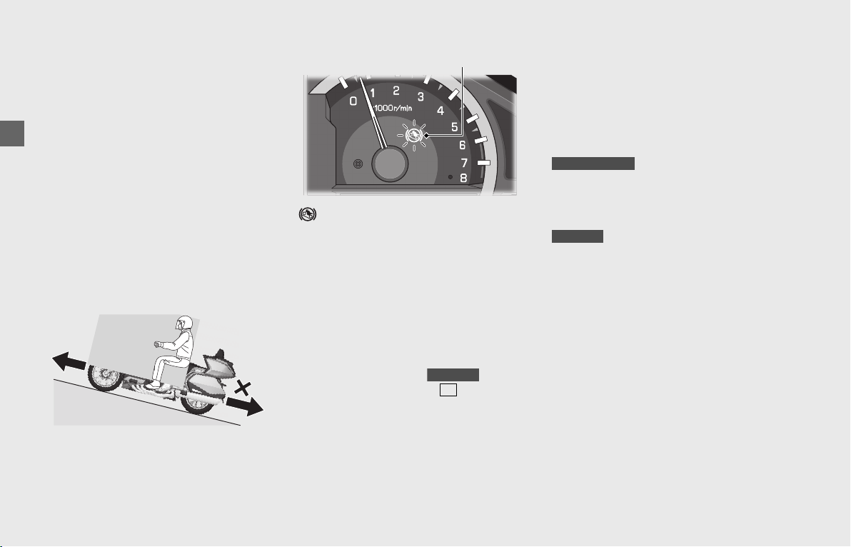
Operation Guide
126
Hill Start Assist
The Hill Start Assist (HSA) temporarily keeps
the vehicle from rolling backward (or
forward) if the brake lever or pedal is
released when stopped on an incline such
as a hill or parking lot slope. Brake hydraulic
pressure is maintained for about 3 seconds
after releasing the brake lever or pedal. This
helps keep the vehicle from rolling
backward (or forward) when first opening
the throttle grip, thereby assisting smooth
movement and lessening the burden
placed on the rider.
HSA is not a replacement for the parking
brake.
Hill start assist (HSA) indicator:
Comes on in white when the HSA is ready
to work, and flashes while the HSA is
working.
The HSA is activated in the following
conditions:
• Combined ABS indicator goes off
• Vehicle is stopped completely
• Throttle grip is closed
• Clutch lever is pulled
• Transmission is in gear ( indicator
goes off)
• Side stand is retracted
❙
Activating the HSA
To activate the HSA, squeeze the brake
lever quickly until the Hill start assist (HSA)
indicator comes on in white and hold the
brake lever.
❙
Releasing the HSA
To start the vehicle, release the brake lever
and gently open the throttle. (The HSA
works about 3 seconds after releasing the
brake lever)
To start the vehicle, release the brake lever,
and then open the throttle grip while
releasing the clutch lever. (The HSA works
about 3 seconds after releasing the brake
lever)
If you lower the side stand or shift the
transmission to neutral while the HSA is
working, the HSA will be cancelled.
HSA may not prevent the vehicle from rolling
backward (or forward) if the vehicle is on a
steep slope.
If the Hill start assist (HSA) indicator
comes on in amber while riding
(P182)
Hill start assist (HSA) indicator
GL1800/B
N
GL1800BD/D/DA
GL1800/B
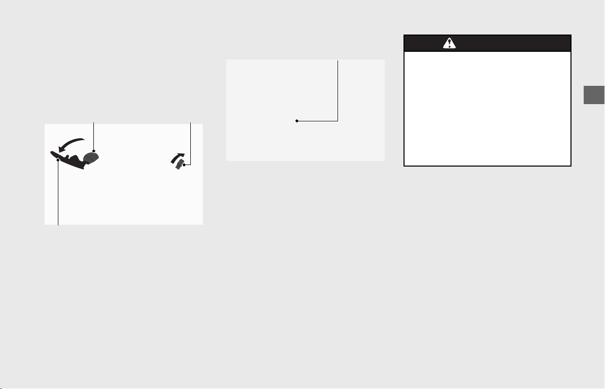
Operation Guide
127
Refueling
Opening the Fuel Fill Cap
!a Open the fairing pocket. (P129)
!b Slide the fuel lid opener to open the fuel
lid.
!c Turn the fuel fill cap counterclockwise
and remove it.
Do not fill with fuel above the lower edge
of the filler neck.
Fuel type: Unleaded gasoline only
Recommended fuel octane number:
Pump Octane Number (PON) 86 or higher.
Tank capacity: 5.5 US gal (21 liters)
❙
Refueling and Fuel Guidelines
(P15)
Closing the Fuel Fill Cap
!a After refueling, be sure to tighten th
fuel fill cap firmly by tighten it clockwise
until it clicks.
!b Close the fuel lid by pushing it un
locks.
!c Close the fairing pocket.
Fuel lid
Fuel lid openerFuel fill cap
Lower edge of
filler neck
WARNINGWARNING
Gasoline is highly flammable and
explosive. You can be burned or
seriously injured when handling
fuel.
• Stop the engine, and keep heat,
sparks, and flame away.
• Handle fuel only outdoors.
• Wipe up spills immediately.
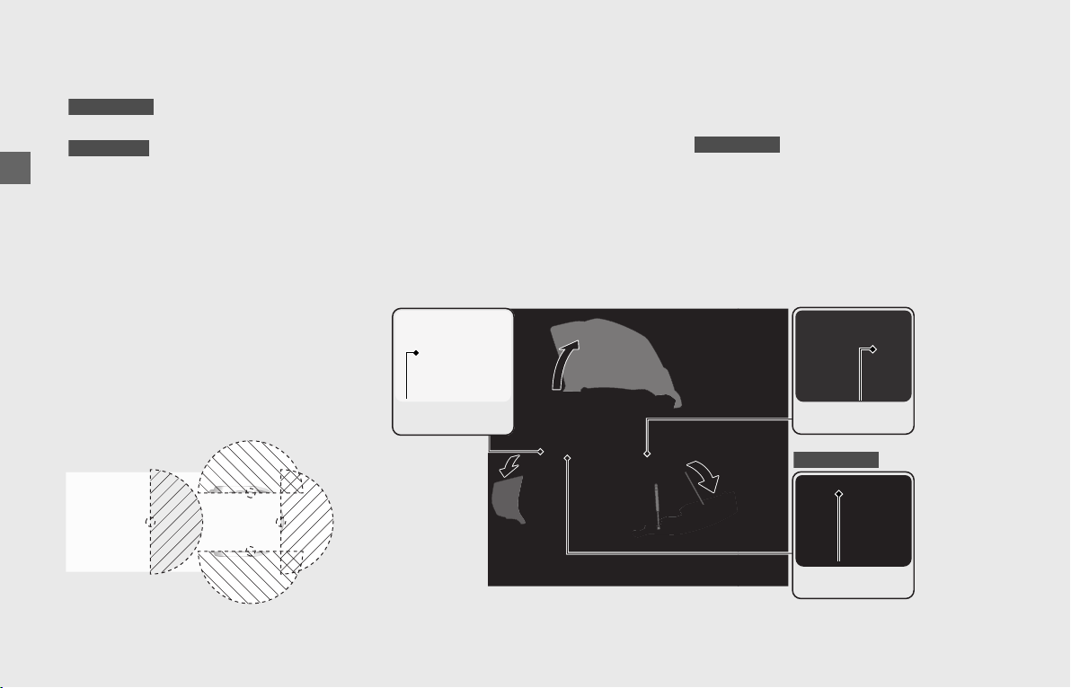
Operation Guide
128
Storage Equipment
Travel Trunk, Saddlebags and
Fairing Pocket
• equipped with the travel
trunk, saddlebags and fairing pocket.
• equipped with the
saddlebags and fairing pocket.
When you enter the operating range of the
Honda SMART Key system with the Honda
SMART Key on you, the travel trunk,
saddlebags and fairing pocket can be
opened.
Using the UNLOCK button on the Honda
SMART Key, you can enable those who
don't possess the key to open the
compartments.
Each compartment can be opened when
the Honda SMART Key is within the shaded
area shown in the illustration.
❙
To Open the Travel Trunk and Saddlebags
The travel trunk and saddlebags are for
lightweight items.
Cargo in the travel trunk and both
saddlebags should not exceed:
20.0 lb (9.0 kg) each
However, regardless of compartment
capacity, be sure you do not exceed the
maximum load and cargo weight limits.
(P237, 239)
Make sure the Honda SMART Key is activated
(P56)
, and then enter the operating range
with the Honda SMART Key.
To open the travel trunk, press the travel
trunk release button.
u The travel trunk unlocks and can be
opened.
To open the saddlebags, press the
saddlebag release button.
u Each saddlebag unlocks and opens.
GL1800/D/DA
GL1800B/BD
GL1800/D/DA
Saddlebag
release button
Saddlebag
release button
Travel trunk
release button
GL1800/D/DA
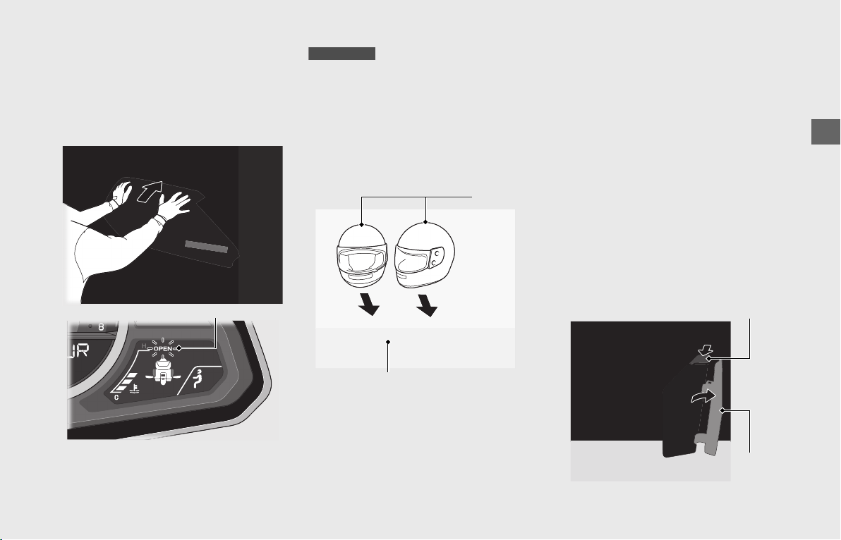
Operation Guide
129
❙
To Close the Travel Trunk and Saddlebags
To close a compartment, place your hands
flat on the edges of its lid and press down
until it is firmly closed. Make sure the travel
trunk and saddlebags “OPEN” indicator is
not blinking before riding.
If the Saddlebags or Travel Trunk
Won’t Open
(P191)
You can store rider and passenger helmets
in the travel trunk.
Store helmets as shown in the illustration.
u Make sure the front of the helmets are
facing rearward.
u Some helmets may not fit in the
compartment due to their size or design.
❙
To Open the Fairing Pocket
Make sure the Honda SMART Key is
activated (P56), and then enter the
operating range with the Honda SMART
Key.
Take care not to store the deactivated
Honda SMART Key in the fairing pocket.
The fairing pocket is for lightweight items.
Cargo in the fairing pocket should not
exceed:
4.5 lb (2.0 kg)
To open the fairing pocket, press the fairing
pocket opener.
“OPEN” indicator
GL1800/D/DA
Helmets
Travel trunk
Fairing pocket opener
Fairing
pocket lid
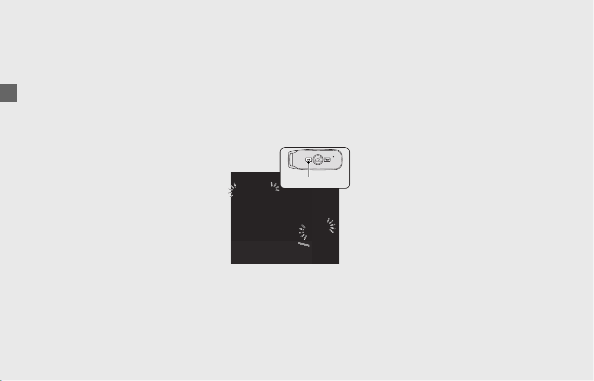
Operation Guide
130
Storage Equipment (Continued)
❙
To Close the Fairing Pocket
To close the fairing pocket, push the lid
until it is firmly closed.
u Do not store valuables in the fairing
pocket.
u Make sure the fairing pocket is closed
before riding.
u Be careful not to flood this area when
washing your vehicle.
Using the remote transmitter
To allow a person who does not possess
the Honda SMART Key to open
compartments, press the UNLOCK button
on the Honda SMART Key (Turn signals
blink 2 times).
When the UNLOCK button is pressed, the
compartments can be opened by someone
who does not have the Honda SMART Key.
If you press the UNLOCK button, but
nobody opens any of the compartments
within about 30 seconds or about 30
seconds have passed after an opened
compartment is closed, the compartments
automatically will relock (Turn signals blinks
once).
u When the 30 days have passed after the
ignition switch is turned to OFF or after the
buttons of the Honda SMART Key is
operated, the remote transmitter will no
longer operate. To reset the system, turn
the ignition switch ON once and then OFF.
UNLOCK button
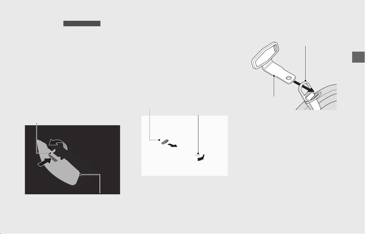
Operation Guide
131
continued
Shelter Case
The shelter case is for lightweight items.
Cargo should not exceed:
6.6 lb (3.0 kg)
Press the shelter case opener, the shelter
case lid opens.
To close the shelter case, push the lid until
it is firmly closed.
u Do not store valuables in the shelter case.
u Make sure the shelter case is closed before
riding.
u Be careful not to flood this area when
washing your vehicle.
Helmet Holder
The helmet holder is located on the left
grab rail.
u Use the helmet holder only when parked.
!a Open the left saddlebag (P128) and
take up the helmet holder hanger.
(P132)
!b Pull the helmet holder release lever
backward to unlock the helmet holder
pin.
!cInsert the helmet holder hanger into the
helmet D-ring.
Except GL1800DA
Shelter case opener
Shelter case lid
Helmet holder
release lever
Helmet holder pin
Helmet D-ring
Helmet holder
hanger
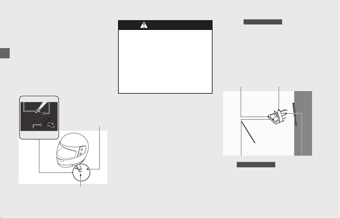
Operation Guide
132
Storage Equipment (Continued)
!d Insert the helmet holder hanger in the
direction shown into the slit on the left
grab rail.
!e To lock the helmet holder, push the
helmet holder button while putting the
helmet holder pin through the hole of
the helmet holder hanger.
!f Close the left saddlebag.
After using the helmet holder hanger,
make sure to store it in the left saddlebag.
Tool Kit , Owner’s
Manual and Helmet Holder Hanger
The tool kit (Canada model only), owner’s
manual and helmet holder hanger are
stored in the left saddlebag.
Secure them with the rubber strap.
Store the Navigation System manual with
the owner’s manual.
❙
Opening the Left Saddlebag
(P128)
Helmet holder hanger
Hole
Pin
Helmet holder
button
Slit
WARNINGWARNING
Riding with a helmet attached to the
holder can interfere with your ability
to safely operate the vehicle and
could lead to a crash in which you
can be seriously hurt or killed.
Use the helmet holder only while
parked. Do not ride with a helmet
secured by the holder.
Canada model only
Tool kit
Canada model only
Owner’s manual
Rubber strap
Helmet holder
hanger
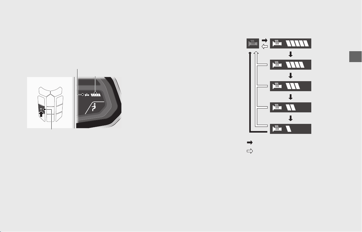
Operation Guide
133
Comfort & Convenience Adjustment
Handle Grip Heater
This vehicle is equipped with a handle grip
heater that warms up your hands during
ride.
Wear gloves to protect your hands from the
heated grips.
❙
Heater Level:
The selected heater level is changed each
time the handle grip heater button is
pressed.
❙
Handle Grip Heater Indicator:
Displayed when the handle grip heater is
on.
If the handle grip heater indicator
blinks:
(P183)
❙
To Operate the Handle Grip Heater
!a Start the engine. (P112)
!b Press the handle grip heater button. The
handle grip heater is on.
!c Select the heater level by pressing the
switch.
uDo not leave the handle grip heater in
the high position for a long time on a
warm day.
❙
To Turn Off the Handle Grip Heater
Press and hold the handle grip heater
button until the handle grip heater
indicator and heater level display goes off.
Do not use the handle grip heater with the
engine at idle for a long time. It may result
in a low (or dead) battery.
Maintains the selected level when the
ignition switch is turned OFF and back to
ON.
Handle grip heater button
Heater level
Handle grip heater indicator
: Press the handle grip heater button
: Press and hold the handle grip heater button
Off
(blank)
Level 5
highest
temperature
Level 1
lowest
temperature
Level 4
Level 3
Level 2
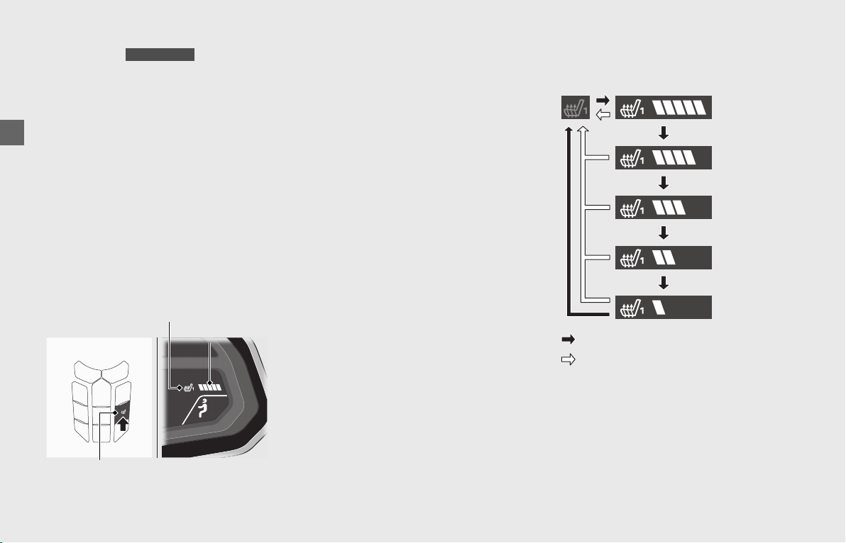
Operation Guide
134
Comfort & Convenience Adjustment (Continued)
Seat Heater
This vehicle is equipped with the seat
heaters that warms up the rider’s seat and
passenger’s seat for comfortable riding on
a cold day.
To operate, adjust the seat heater buttons
with the engine started.
Do not use the seat heaters with the engine
at idle for a long time. It may result in a low
(or dead) battery.
❙
Rider Seat Heater Button
The rider seat heater button is located on
the center panel.
The selected heater level is changed each
time the seat heater button is pressed.
❙
To Operate the Rider Seat Heater
!aStart the engine. (P112)
!bPress the rider seat heater button. The
rider seat heater is on.
!cSelect the heater level by pressing the
rider seat heater button.
u Do not leave the seat heater in the
high position for a long time on a
warm day.
❙
To Turn Off the Rider Seat Heater
Press and hold the rider seat button until
rider seat heater indicator and heater level
display goes off.
Maintains the selected level when the
ignition switch is turned OFF and then back
ON.
Do not use the seat heaters with the engine
at idle for a long time. It may result in a low
(or dead) battery.
Do not use the seat heater when the seat is
torn, cut or damaged as you can get
burned.
Do not apply excessive stress to the seat,
e.g. by securing articles to it with tie-down
straps during transportation.
GL1800/D/DA
Rider seat heater button
Rider seat heater indicator
Heater level
: Press the rider seat heater button
Level 5
highest
temperature
Level 4
Off
(blank)
Level 3
Level 2
Level 1
lowest
temperature
: Press and hold the rider seat heater button
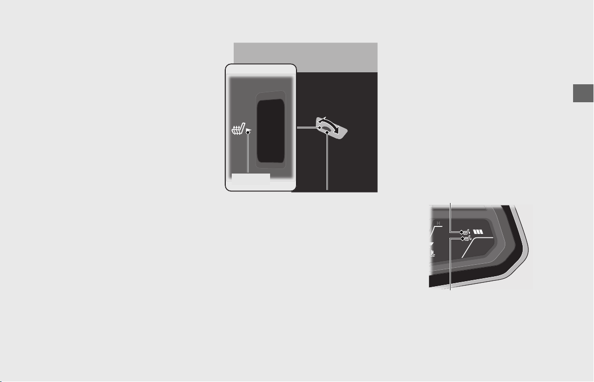
Operation Guide
135
❙
Passenger Seat Heater Switch
The passenger seat heater switch is located
on the left saddlebag.
The passenger seat heater switch has 6
positions (OFF, 1, 2, 3, 4, 5 indicated on the
switch).
❙
To Operate the Passenger Seat Heater
!a Start the engine. (P112)
!b Select the heater level by rotating the
passenger seat heater switch.
To set the desired heater level, align the
number on the switch with the mark
nearby the switch.
u The highest temperature is 5 and the
lowest temperature is 1.
u Do not leave the seat heater in the
high position for a long time on a
warm day.
❙
To Turn Off the Passenger Seat Heater
Rotate the passenger seat heater switch
and align the OFF on the switch with the
mark.
The passenger seat heater indicator goes
off.
Do not use the seat heater with the engine
at idle for a long time. It may result in a low
(or dead) battery.
Do not use the seat heater when the seat is
torn, cut or damaged as you can get
burned.
Do not apply excessive stress to the seat,
e.g. by securing articles to it with tie-down
straps during transportation.
❙
Seat Heater Indicators
Displayed when each seat heater is on. If
the seat heater indicator blinks, see your
dealer for servicing.
If the seat heater indicators blink:
(P184)
Passenger seat
heater switch
mark
Passenger seat
heater indicator
Rider seat heater indicator
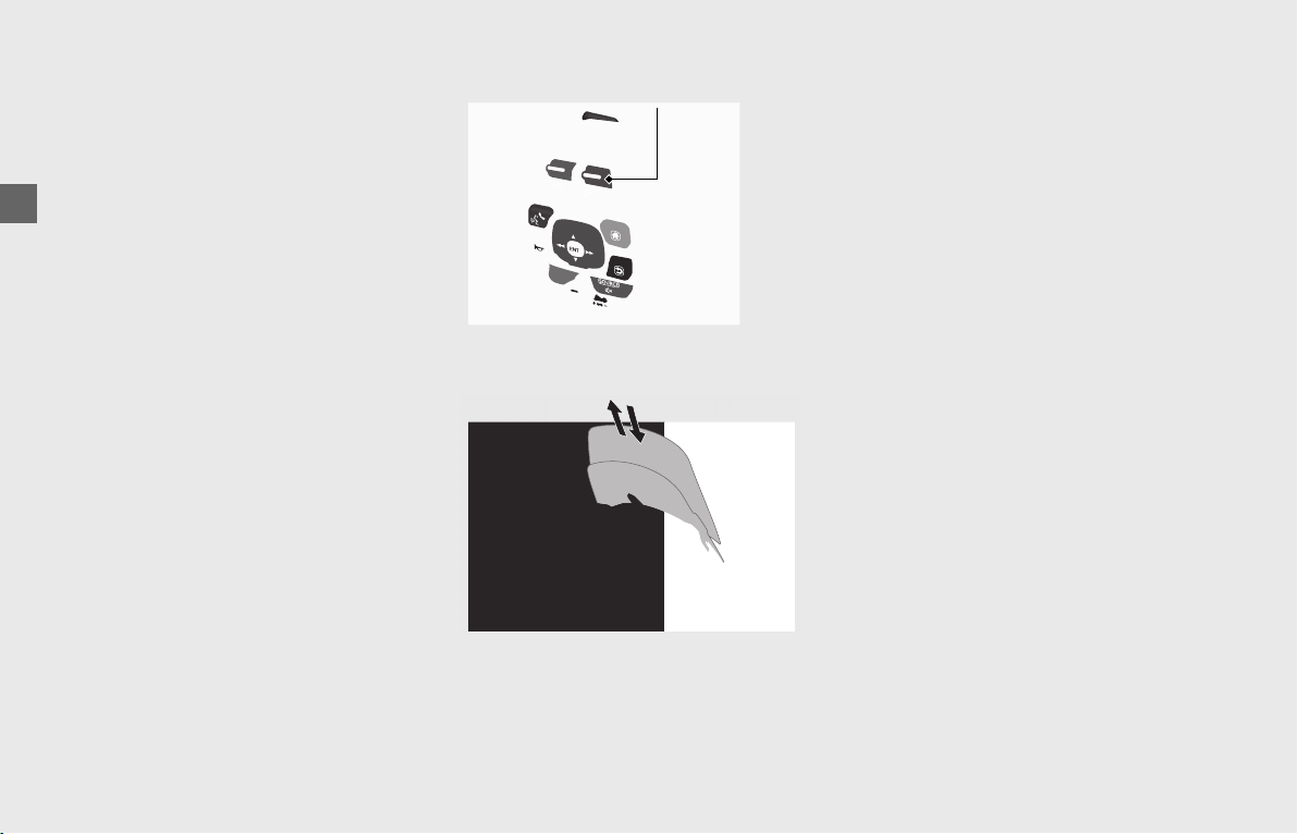
Operation Guide
136
Comfort & Convenience Adjustment (Continued)
Adjustable Windscreen
You can adjust your windscreen height
higher or lower according to your
preference.
If possible, you should adjust your
windscreen height to below eye level for
better visibility.
❙
To Adjust Windscreen Height
Turn the ignition switch to ON. When
traveling faster than 3 mph (5 km/h), the
windscreen automatically adjusts to the
position it was at when the ignition switch
was last turned to OFF.
Pushing the windscreen adjusting lever
upwards raises the windscreen, and
pushing it downwards lowers the
windscreen.
The windscreen will be raised or lowered
while the adjusting lever is being pressed.
When you lower the windscreen, make
sure the new position will allow safe
operation of the vehicle.
Turning the ignition switch to OFF will
automatically lower the windscreen to its
original position.
To keep the windscreen raised after turning
off the electrical system, such as when
washing it, turn the ignition switch to OFF
while pushing the windscreen adjusting
lever upwards.
Windscreen adjusting lever
Pushing lever
upward
Pushing lever
downward

Operation Guide
137
Windscreen Ventilation Louver
You can utilize the windscreen ventilation
louver to direct the flow of fresh air.
❙
To Operate the Windscreen Ventilation
Louver
Press the release button, then the
windscreen ventilation louver pops-up.
❙
To Close the Windscreen Ventilation
Louver
Push the center of the louver until the
louver is firmly closed.
Windscreen ventilation louver
Release button

Maintenance
Please read “Importance of Maintenance” and “Maintenance Fundamentals” carefully before attempting any maintenance.
Refer to “Specifications” for service data.
An optional larger tool kit may be available. Check with your Honda dealer’s parts department.
Importance of Maintenance ................ P. 139
Maintenance Schedule......................... P. 140
Maintenance Fundamentals ................ P. 143
Removing & Installing Body Components
... P. 153
Battery ................................................ P. 153
Cylinder Head Side Cover.................... P. 154
Fog Light Cover................................... P. 155
Left Engine Side Cover ........................ P. 155
Side Cover........................................... P. 156
Spark Plug............................................. P. 157
Engine Oil ............................................. P. 158
Coolant.................................................. P. 162
Final Drive Oil ....................................... P. 163
Brakes .................................................... P. 164
Side Stand ............................................ P. 167
Clutch.................................................... P. 168
Throttle................................................. P. 169
Crankcase Breather.............................. P. 170
Other Adjustments .............................. P. 171
Headlight Aim ................................... P. 171
Clutch and Brake Levers .................... P. 171
Electrical Adjustable Suspension
................................. P. 172
Rear Suspension ......... P. 173
Other Replacement .............................. P. 174
Honda SMART Key Battery................. P. 174
GL1800/D/DA
GL1800B/BD
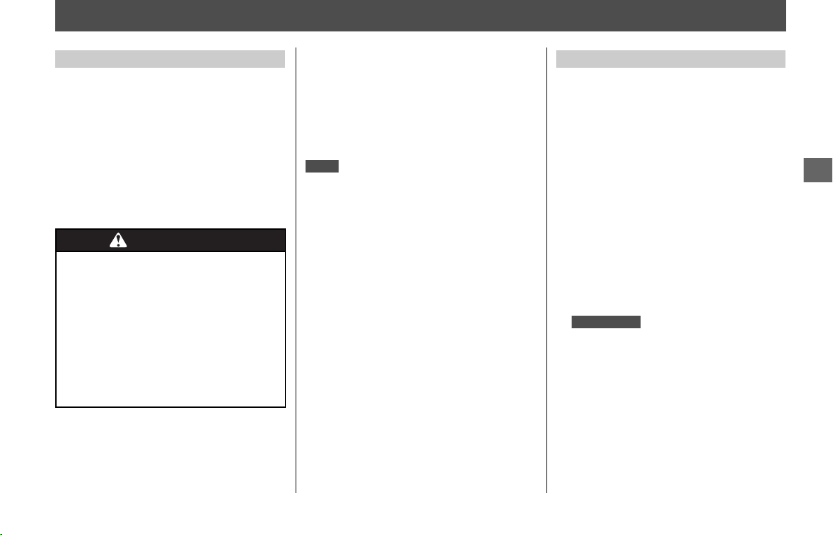
139
Maintenance
Importance of Maintenance
Keeping your vehicle well-maintained is
absolutely essential to your safety and to
protect your investment, obtain maximum
performance, avoid breakdowns, and
reduce air pollution. Maintenance is the
owner’s responsibility. Be sure to inspect
your vehicle before each ride, and perform
the periodic checks specified in the
Maintenance Schedule.
2 P. 140
For information about the exhaust emission
and noise emission requirements of the
U.S. Environmental Protection Agency
(EPA), the California Air Resources Board
(CARB), and the Environment and Climate
Change Canada (ECCC).
2 P. 227
Maintenance, replacement or repair of
the emission control devices and
systems may be performed by any
vehicle repair establishment or
individual using parts that are
“certified“ to EPA standards.
Always read the maintenance instructions
before you begin each task, and make sure
that you have the tools, parts, and skills
required.
We cannot warn you of every conceivable
hazard that can arise in performing
maintenance. Only you can decide whether
or not you should perform a given task.
Follow these guidelines when performing
maintenance.
● Stop the engine and turn the ignition
switch to OFF.
● Place your vehicle on a firm, level surface
using the side stand, center stand
( ) or a maintenance stand to
provide support.
● Allow the engine, muffler, brakes, and
other high-temperature parts to cool
before servicing as you can get burned.
● Run the engine only when instructed,
and do so in a well-ventilated area.
Importance of Maintenance
WARNINGWARNING
Improperly maintaining your vehicle
or failing to correct a problem
before you ride can cause a crash in
which you can be seriously hurt or
killed.
Always follow the inspection and
maintenance recommendations and
schedules in this owner’s manual.
USA
Maintenance Safety
GL1800/D/DA

140
Maintenance
Maintenance Schedule
The maintenance schedule specifies the
maintenance requirements necessary to
ensure safe, dependable performance, and
proper emission control.
Maintenance work should be performed in
accordance with Honda’s standards and
specifications by properly trained and
equipped technicians. Your dealer meets all
of these requirements. All scheduled
maintenance is considered a normal owner
operating cost and will be charged to you
by your dealer. Keeping an accurate
maintenance record will help ensure your
vehicle is properly maintained.
2 P. 142
Make sure whoever performs the
scheduled maintenance completes the
maintenance record. Retain all service
documents. If you sell your vehicle, these
service documents should be transferred
with the vehicle to the new owner.
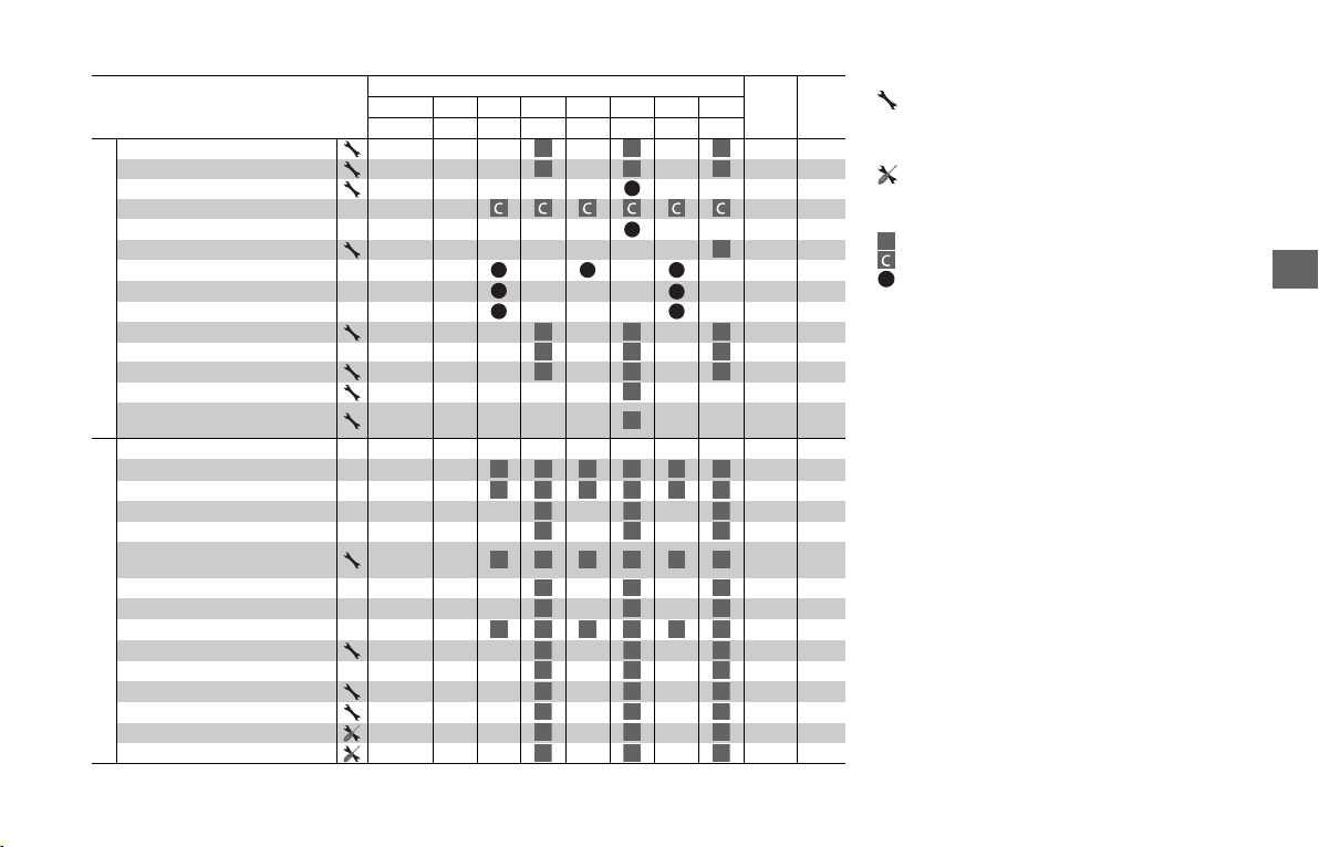
141
Maintenance
Items
Frequency*
1
Regular
Replace
Refer
to
page
x 1,000 mi 0.6 4 8 12 16 20 24
x 1,000 km 1.0 6.4 12.8 19.2 25.6 32.0 38.4
Emission-related Items
Fuel Line –
Throttle Operation 169
Air Cleaner
*
2
–
Crankcase Breather
*
3
170
Spark Plug 157
Valve Clearance –
Engine Oil
1 Year
158
Engine Oil Filter 159
Clutch Oil Filter (GL1800BD/D/DA) 161
Engine Idle Speed –
Radiator Coolant
*
5
3 Years 162
Cooling System –
Secondary Air Supply System –
Evaporative Emission Control
System
*
4
–
Non-Emission-Related Items
Final Drive Oil 3 Years 163
Brake Fluid
*
5
2 Years
164
Brake Pads Wear 165
Brake System 143
Brake Light Switch 166
Brake Lock Operation
(GL1800BD/D/DA)
166
Headlight Aim 171
Clutch System (GL1800/B) 171
Clutch Fluid
*
5
(GL1800/B)
2 Years
168
Reverse Operation (GL1800/B) –
Side Stand 167
Suspension –
Nuts, Bolts, Fasteners –
Wheels/Tires –
Steering Head Bearings –
I I I
I I I
R
R
I
R
R
R
R
R
R R
I I I
I I I
I I I
I
I
I I I I I I
I
I
I
I
I
I
I
I
I
I
I
I
I I I I I I
I I I
I I I
I I I I I I
I
I
I
I
I
I
I
I
I
I
I
I
I
I
I
I
I
I
Maintenance Level
: Intermediate. We recommend service by your dealer, unless
you have the necessary tools and are mechanically skilled.
Procedures are provided in an official Honda Service Manual.
(2 P. 232)
: Technical. In the interest of safety, have your vehicle serviced
by your dealer.
Maintenance Legend
: Inspect (clean, adjust, lubricate, or replace, if necessary)
:Clean
:Replace
Notes:
*1 : At higher odometer reading, repeat at the frequency interval
established here.
*2 : Service more frequently when riding in unusually wet or dusty
areas.
*3 : Service more frequently when riding in rain or at full throttle.
*4 : 50 STATE (meets California)
*5 : Replacement requires mechanical skill.
I
R
Maintenance Schedule
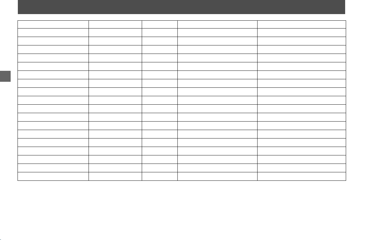
142
Maintenance
Maintenance Record
Distance Odometer Date Performed By: Notes
600 miles (1,000 km)
4,000 miles (6,400 km)
8,000 miles (12,800 km)
12,000 miles (19,200 km)
16,000 miles (25,600 km)
20,000 miles (32,000 km)
24,000 miles (38,400 km)
28,000 miles (44,800 km)
32,000 miles (51,200 km)
36,000 miles (57,600 km)
40,000 miles (64,000 km)
44,000 miles (70,400 km)
48,000 miles (76,800 km)
52,000 miles (83,200 km)
56,000 miles (89,600 km)
60,000 miles (96,000 km)
64,000 miles (102,400 km)
68,000 miles (108,800 km)

143
Maintenance
Maintenance Fundamentals
To ensure safety, it is your responsibility to
perform a pre-ride inspection and make
sure that any problem you find is corrected.
A pre-ride inspection is a must, not only for
safety, but because having a breakdown, or
even a flat tire, can be a major
inconvenience.
Check the following items before you get
on your vehicle:
● Tire tread wear and air pressures are
within limits. 2 P. 150
● Lights, horn, and turn signals operate
normally.
Check the following items if you are
carrying a passenger or cargo:
● Combined weight is within load limits.
2 P. 237, 239
● Cargo is secured properly.
● Suspension is adjusted to suit load.
2 P. 172, 173
Check the following items after you get on
your vehicle:
● Throttle action moves smoothly without
binding. 2 P. 169
● Brake lever and pedal operate normally.
● Check the fuel level and refuel when
needed. 2 P. 15, 127
● Engine stop switch functions properly.
2 P. 48
Check the following items at regular
intervals:
● Oil level is between the upper and lower
level marks. 2 P. 158
● Brake fluid level is
Front: above the LWR mark. 2 P. 164
Rear: above the LWR mark. 2 P. 164
● Clutch fluid level is above the
LWR mark. 2 P. 168
● Engine coolant level is between the
UPPER and LOWER level marks.
2 P. 162
● Side stand functions properly. 2 P. 167
● Parking brake works
properly.
2 P. 166
Pre-ride Inspection
GL1800/B
GL1800BD/D/DA
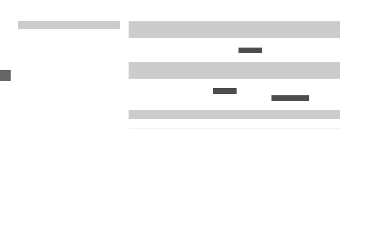
Maintenance Fundamentals
144
Maintenance
You should also perform other periodic
maintenance checks at least once a month
regardless of how often you ride, or more
often if you ride frequently.
Also, check the odometer reading against
the Maintenance Schedule and perform all
maintenance that is due.
2 P. 140
Periodic Checks
Tires and wheels
Check the air pressure (2 P. 150), examine tread for wear and
damage (2 P. 150), and check the wheels for damage.
Fluid levels
Check the engine oil level (2 P. 158), engine coolant level (2 P.
162), clutch fluid level ( ) (2 P. 168), final drive oil level
(
2 P. 163) and brake fluid level (2 P. 164).
Lights
Check that the headlight, brake light, taillight, turn signals and
license plate light are working properly.
Controls
Check the freeplay of the throttle grip (2 P. 169). Check the
clutch lever ( ) (
2 P. 171), front brake lever (2 P. 171),
rear brake pedal, and parking brake ( ) (2 P. 166)
operate properly.
Fuses Check that you have a full supply of spare fuses.
Nuts & bolts Check the major nuts and bolts, and tighten as needed.
GL1800/B
GL1800/B
GL1800BD/D/DA
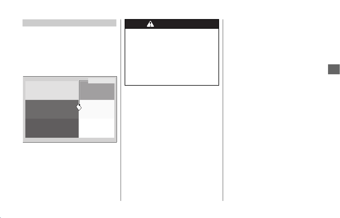
Maintenance Fundamentals
145
Maintenance
Always use Honda Genuine Parts or their
equivalents to ensure reliability and safety.
When ordering colored components,
specify the model name, color and code
mentioned on the color label.
The color label is attached on the reverse
side of the fuel lid.
2 P. 127
Replacing Parts
Color label
WARNINGWARNING
Installing non-Honda parts may
make your vehicle unsafe and cause
a crash in which you can be seriously
hurt or killed.
Always use Honda Genuine Parts or
equivalents that have been designed
and approved for your vehicle.
Maintenance Fundamentals
146
Maintenance
Your vehicle has a maintenance-free type
battery. You do not have to check the
battery electrolyte level or add distilled
water. Clean the battery terminals if they
become dirty or corroded.
Do not remove the battery cap seals. There
is no need to remove the cap when
charging.
❙
What to do in an emergency
If any of the following occur, immediately
see your doctor.
● Electrolyte splashes into your eyes:
u Wash your eyes repeatedly with cool
water for at least 15 minutes. Using
water under pressure can damage
your eyes.
● Electrolyte splashes onto your skin:
u Remove affected clothing and wash
your skin thoroughly using water.
● Electrolyte splashes into your mouth:
u Rinse mouth thoroughly with water,
and do not swallow.
WARNING: Battery posts, terminals, and
related accessories contain lead and lead
compounds.
Wash your hands after handling.
Battery
NOTICE
An improperly disposed of battery can be harmful to
the environment and human health.
Always confirm local regulations for proper battery
disposal instruction.
WARNINGWARNING
The battery gives off explosive
hydrogen gas during normal
operation.
A spark or flame can cause the
battery to explode with enough
force to kill or seriously hurt you.
Wear protective clothing and a face
shield, or have a skilled mechanic do
the battery servicing.
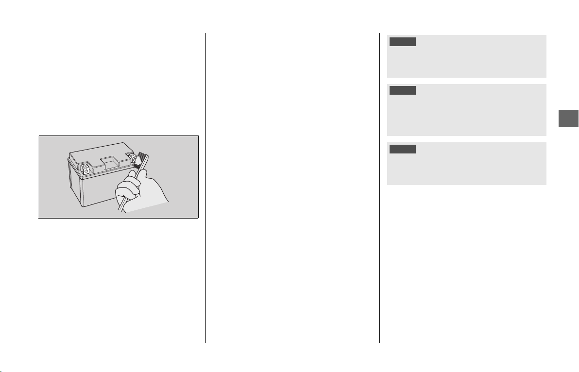
Maintenance Fundamentals
147
Maintenance
❙
Cleaning the Battery Terminals
1.
Remove the battery. 2 P. 153
2.
If the terminals are starting to corrode
and are coated with a white substance,
wash with warm water and wipe clean.
3.
If the terminals are heavily corroded,
clean and polish the terminals with a
wire brush or sandpaper. Wear safety
glasses.
4.
After cleaning, reinstall the battery.
The battery has a limited life span. Consult
your dealer about when you should replace
the battery. Always replace the battery with
another maintenance-free battery of the
same type.
❙
Charging
If you use electrical accessories that drain
the battery or you do not ride frequently,
we recommend that you charge the battery
every 30 days using a charger designed
specifically for your Honda, which can be
purchased from your dealer. Read the
information that came with your battery
charger and follow the instructions on the
battery. Avoid using an automobile-type
battery charger, as these can overheat a
vehicle battery and cause permanent
damage.
Make sure the ignition switch is turned to
OFF before charging the battery.
NOTICE
Improper charging can damage the battery. If you can’t
charge the battery or it appears unable to hold a
charge, contact your dealer.
NOTICE
Jump starting using an automobile battery can damage
your vehicle’s electrical system and is not
recommended. Bump starting is also not
recommended.
NOTICE
Installing non-Honda electrical accessories can
overload the electrical system, discharging the battery
and possibly damaging the system.
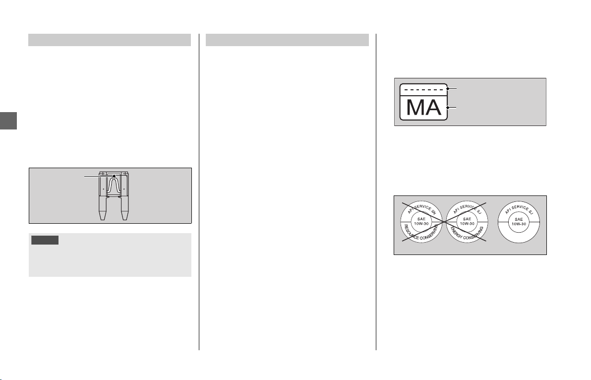
Maintenance Fundamentals
148
Maintenance
Fuses protect the electrical circuits on your
vehicle. If something electrical on your
vehicle stops working, check for and
replace any blown fuses.
2 P. 209
❙
Inspecting and Replacing Fuses
Turn the ignition switch OFF to remove and
inspect fuses. If a fuse is blown, replace
with a fuse of the same rating. For fuse
ratings, see “Specifications.”
2 P. 238, 240
If a fuse fails repeatedly, you likely have an
electrical fault. Have your vehicle inspected
by your dealer.
Engine oil consumption varies and oil quality
deteriorates according to riding conditions
and time elapsed.
Check the engine oil level regularly, and add
the recommended engine oil if necessary.
Dirty oil or old oil should be changed as soon
as possible.
❙
Selecting the Engine Oil
For recommended engine oil, see
“Specifications.” 2 P. 237, 239
If you use non-Honda engine oil, check the
label to make sure that the oil satisfies all of
the following standards:
● JASO T 903 standard*
1
: MA
● SAE standard*
2
: 10W-30
● API classification*
3
: SG or higher
*1.
The JASO T 903 standard is an index for engine
oils for 4-stroke motorcycle engines. There are
two classes: MA and MB. For example, the
following label shows the MA classification.
*2.
The SAE standard grades oils by their viscosity.
*3.
The API classification specifies the quality and
performance rating of engine oils. Use SG or
higher oils, excluding oils marked as “Energy
Conserving” or “Resource Conserving” on the
circular API service symbol.
Fuses
NOTICE
Replacing a fuse with one that has a higher rating
greatly increases the chance of damage to the electrical
system.
Blown fuse
Engine Oil
Oil code
Oil classification
RecommendedNot recommended
Maintenance Fundamentals
149
Maintenance
Do not add or replace brake fluid, except in an
emergency. Use only fresh brake fluid from a
sealed container. If you do add fluid, have the
brake and clutch system serviced by your
dealer as soon as possible.
Pro Honda HP Coolant is a pre-mixed
solution of antifreeze and distilled water.
A concentration of antifreeze below 40%
will not provide proper corrosion and cold
temperature protection.
A concentration of up to 60% will provide
better protection in colder climates.
Service more frequently when riding in rain,
at full throttle, or after the vehicle is
washed or overturned. Service if the
deposit level can be seen in the transparent
section of the drain tube.
If the drain tube overflows, the air filter
may become contaminated with engine oil
causing poor engine performance.
2 P. 170
Brake Fluid (Clutch Fluid)
NOTICE
Brake fluid can damage plastic and painted surfaces.
Wipe up spills immediately and wash thoroughly.
Recommended brake fluid:
Honda DOT 4 Brake Fluid or equivalent
WARNINGWARNING
Clean filler cap before removing.
Use only DOT 4 fluid from a sealed
container.
Final Drive Oil
Recommended final drive oil:
Hypoid gear oil SAE 80
Recommended Coolant
Concentration:
50% antifreeze and 50% distilled
water
NOTICE
Using coolant not specified for aluminum engines or
tap/mineral water can cause corrosion.
Crankcase Breather

Maintenance Fundamentals
150
Maintenance
❙
Checking the Air Pressure
Even though your vehicle is equipped with
tire pressure monitoring system (TPMS),
visually inspect your tires and use an air
pressure gauge to measure the air pressure
at least once a month or any time you think
the tires look low. Always check air
pressure when your tires are cold.
Do not adjust tire pressure using the values
indicated on the tire pressure gauge of the
INFO 1 display.
The tire pressure values indicated on the
tire pressure gauge of the INFO 1 display
may not match actual values, because the
tire pressure gauge indication is not
updated instantly and is updated only at a
certain period.
Even if the direction of the valve stem is
changed, do not return it to the original
position. Have your vehicle inspected by
your dealer.
❙
Inspecting for Damage
Inspect the tires for
cuts, slits, or cracks
that exposes fabric
or cords, or nails or
other foreign
objects embedded
in the side of the
tire or the tread. Also inspect for any
unusual bumps or bulges in the side walls
of the tires.
❙
Inspecting for Abnormal Wear
Inspect the tires for
signs of abnormal
wear on the
contact surface.
Tires (Inspecting/Replacing)
GL1800/D/DA
Left side
Valve stem
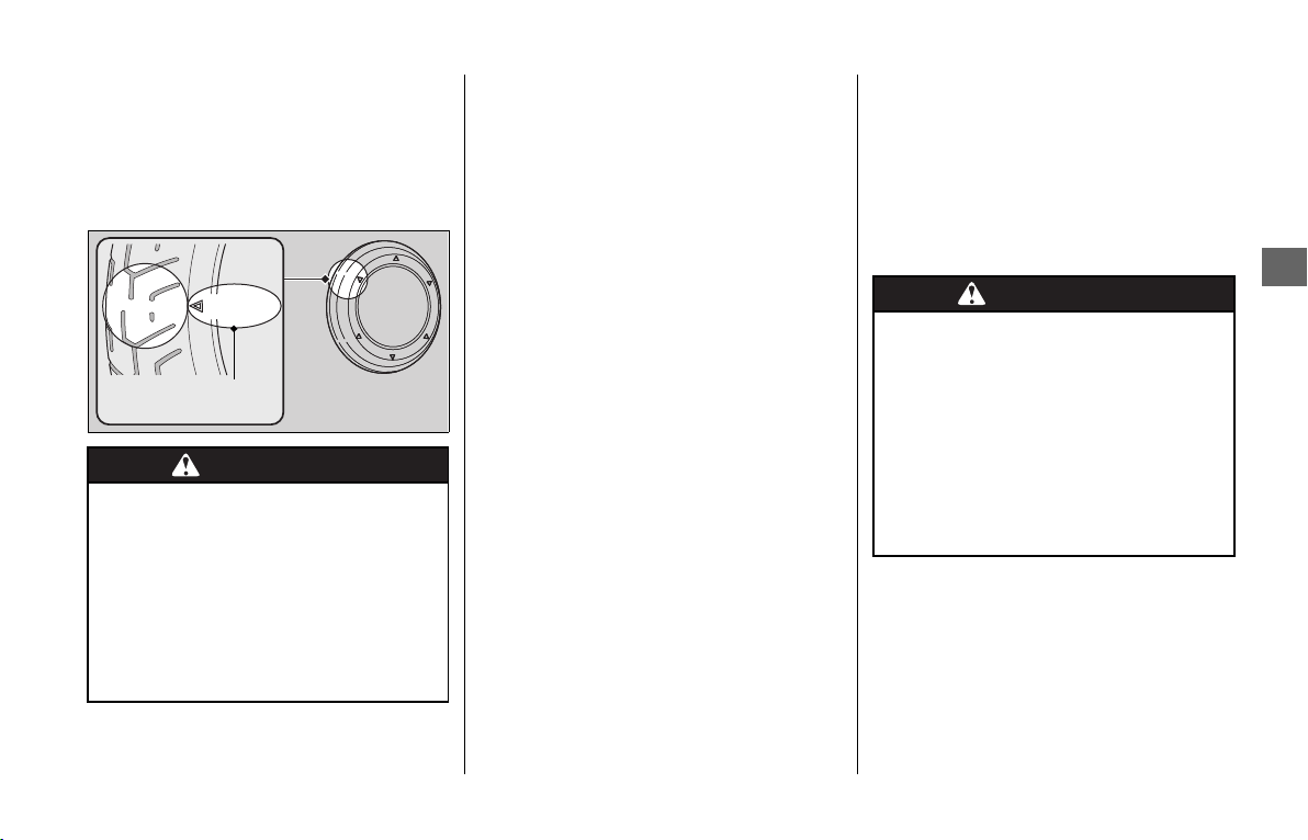
Maintenance Fundamentals
151
Maintenance
❙
Inspecting Tread Depth
Inspect the tread wear indicators. If they
become visible, replace the tires
immediately.
For safe riding, you should replace the tires
when the minimum tread depth is reached.
Have your tires replaced by your dealer.
For recommended tires, air pressure and
minimum tread depth, see
“Specifications.”
2 P. 237, 239
Follow these guidelines whenever you
replace tires.
● Use the recommended tires or
equivalents of the same size,
construction, speed rating, and load
range.
● Have the wheel balanced with Honda
Genuine balance weights or equivalent
after the tire is installed.
● Do not install a tube inside a tubeless tire
on this vehicle. Excessive heat build-up
can cause the tube to burst.
● Use only tubeless tires on this vehicle.
The rims are designed for tubeless tires,
and during hard acceleration or braking,
a tube-type tire could slip on the rim and
cause the tire to rapidly deflate.
● Each wheel is equipped with a tire
pressure sensor mounted inside the tire
behind the valve stem. You must use
TPMS specific wheels. Not using TPMS
specific wheels can cause an air leak, a
tire pressure monitoring system failure,
or both.
WARNINGWARNING
Riding on tires that are excessively
worn or improperly inflated can
cause a crash in which you can be
seriously hurt or killed.
Follow all instructions in this owner’s
manual regarding tires inflation and
maintenance.
Wear indicator
location mark
or TWI
WARNINGWARNING
Installing improper tires on your
vehicle can adversely affect handling
and stability, and can cause a crash
in which you can be seriously hurt or
killed.
Always use the size and type of tires
recommended in this owner’s
manual.

Maintenance Fundamentals
152
Maintenance
The service life of your tires is dependent on
many factors, including, but not limited to,
riding habits, road conditions, vehicle
loading, tire air pressure, maintenance
history, speed, and environmental
conditions (even when the tires are not in
use).
In addition to your regular inspections and
maintenance, it is recommended that you
have annual inspections performed once
the tires reach 5 years old. It is also
recommended that all tires be removed
from service after 10 years from the date of
manufacture, regardless of their condition
or state of wear.
The last four digits of the TIN (tire
identification number) indicate the date of
manufacture.
❙
Tire Identification Number (TIN)
The tire identification number (TIN) is a
group of numbers and letters located on
the sidewall of the tire.
This vehicle is equipped with a viscous type
air cleaner element which cannot be
cleaned with compressed air or otherwise
without degrading its performance.
If the filter becomes dirty, replace it with a
new one.
Tire Service Life
DOT XXXX XXXX 22 09
DOT: This indicates that the tire meets
all requirements of the U.S.
Department of Transportation.
!
a XXXX: Factory code
!b XXXX: Tire type code
!
c 22 09:
year).
Example: week 22 in year 09.
!a !b !c
Tire Labeling Example
Tire identification
number (TIN)
Air Cleaner
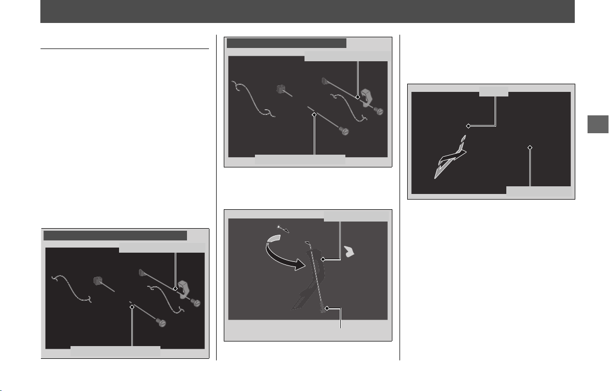
153
Maintenance
Removing & Installing Body Components
Battery
❙
Removal
Make sure the ignition switch is turned to
OFF.
After turning the ignition switch OFF, wait
more than 60 seconds and then remove the
negative cable of the battery. Because the
electrical system may not function
correctly.
1.
Remove the left side cover. 2 P. 156
2.
Disconnect the negative - terminal
from the battery.
3.
Disconnect the positive + terminal from
the battery.
4.
Remove the battery holder bolt.
5.
Swing the battery holder as shown to
avoid interference against the seat.
6.
Remove the battery holder from the
hook.
7.
Remove the battery taking care not to
drop the terminal nuts.
Positive + terminal
Except GL1800BD/D/DA Canada model
Negative - terminal
GL1800BD/D/DA Canada model
Positive + terminal
Negative - terminal
Battery holder bolt
Battery holder
Battery holder
Hook
continued
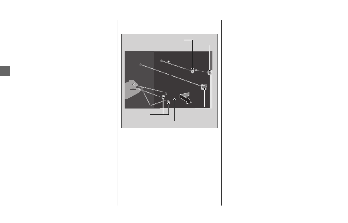
Removing & Installing Body Components u Cylinder Head Side Cover
154
Maintenance
❙
Installation
Install the parts in the reverse order of
removal. Always connect the positive +
terminal first. Make sure that bolts and nuts
are tight.
Make sure the clock information is correct
after the battery is reconnected.
2 P. 78
For proper handling of the battery, see
“Maintenance Fundamentals.”
2 P. 143
“Battery Goes Dead.” 2 P. 207
Cylinder Head Side Cover
The right and left cylinder head side cover
can be removed in the same way.
❙
Removal
1.
Remove the fog light cover. 2 P. 155
2.
Remove the screw A and B.
3.
Remove the prongs from the lower
cover.
4.
Pull the grommet from the boss on the
cylinder head and slide the cylinder head
side cover forward, then remove it.
❙
Installation
Install the parts in the reverse order of
removal.
Screw A
Screw B
Cylinder head side cover
Prongs
Grommet
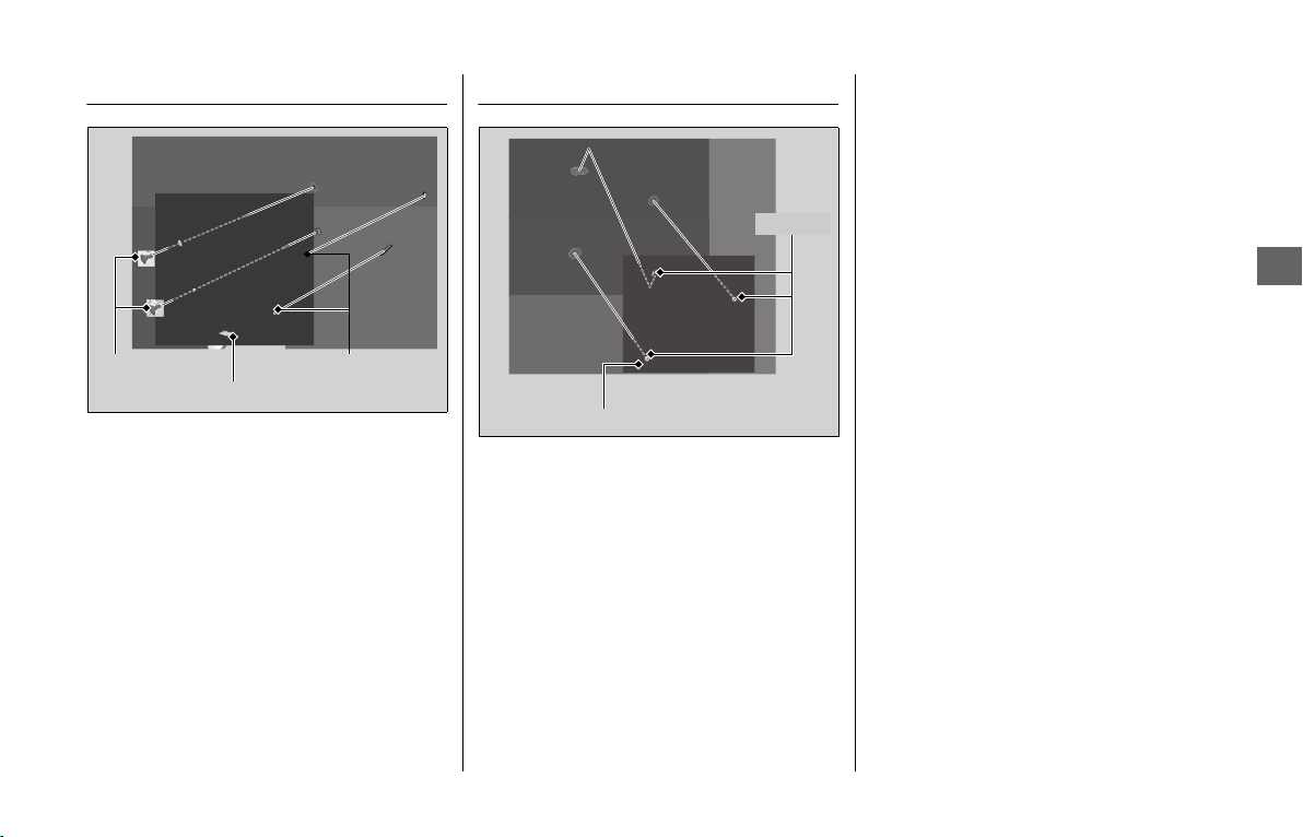
Removing & Installing Body Components u Fog Light Cover
155
Maintenance
Fog Light Cover
The right and left fog light cover can be
removed in the same way.
❙
Removal
1.
Remove the screws.
2.
Release the tabs from the cylinder head
side cover.
3.
Remove the fog light cover.
❙
Installation
Install the parts in the reverse order of
removal.
Left Engine Side Cover
❙
Removal
1.
Release the bosses from the grommets.
2.
Remove the left engine side cover.
❙
Installation
Install the parts in the reverse order of
removal.
Screws Tabs
Fog light cover
Bosses
Left engine side cover
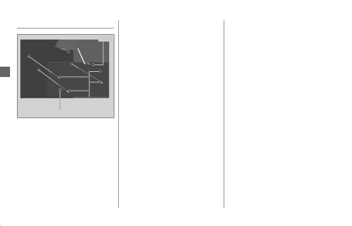
Removing & Installing Body Components u Side Cover
156
Maintenance
Side Cover
The right and left side cover can be
removed in the same way.
❙
Removal
1.
Open the saddlebag. 2 P. 128
2.
Remove the bosses.
3.
Release the tab from the saddlebag
cover.
4.
Remove the side cover.
❙
Installation
Install the parts in the reverse order of
removal.
Bosses
Tab
Side cover
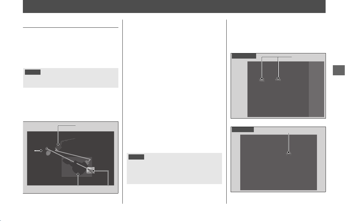
157
Maintenance
Spark Plug
Changing Spark Plug
For the recommended spark plugs, see
“Specifications.”
2 P. 237, 239
Use only the recommended type of spark
plugs in the recommended heat range.
1.
Remove the left and right fog light
covers. 2 P. 155
2.
Remove the left and right cylinder head
side covers. 2 P. 154
3.
Disconnect the connectors from the
direct ignition coils.
4.
Remove the bolts and direct ignition
coils.
5.
Clean any dirt around the spark plug
bases.
6.
Remove the spark plugs using a suitable
spark plug wrench.
7.
Install new spark plugs. With the plug
washers attached, thread the spark
plugs in by hand to prevent cross-
threading.
8.
Tighten the spark plugs.
• Installing a new plug, tighten it twice
to prevent loosening:
a) First, tighten the plug:
1 turn after it seats.
b)Then loosen the plug.
c) Next, tighten the plug again:
1/8 turn after it seats.
9.
Install the parts in the reverse order of
removal.
u When reinstalling, make sure the wire
grommets are installed in place as
shown.
NOTICE
Using a spark plug with an improper heat range can
cause engine damage.
BoltDirect ignition coil
ConnectorSpark plug
NOTICE
An improperly tightened spark plug can damage the
engine. If a plug is too loose, a piston may be
damaged. If a plug is too tight, the threads may be
damaged.
Right side
Grommets
Left side
Grommet
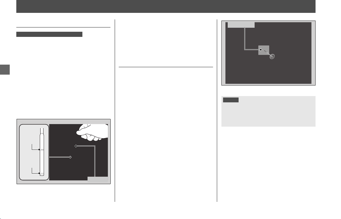
158
Maintenance
Engine Oil
Checking the Engine Oil
Check the engine oil with the Idling Stop
system disabled. 2 P. 61
1.
If the engine is cold, idle the engine for
3 to 5 minutes.
2.
Turn the ignition switch OFF and wait
for 2 to 3 minutes.
3.
Place your vehicle in an upright position
on a firm, level surface.
4.
Remove the dipstick and wipe it clean.
5.
Insert the dipstick until it seats, but don't
screw it in.
6.
Check that the oil level is between the
upper level and lower level marks on the
dipstick.
7.
Securely install the dipstick.
Adding Engine Oil
If the engine oil is below or near the lower
level mark, add the recommended engine
oil.
2 P. 148, 237, 239
1.
Remove the oil fill cap. Add the
recommended oil until it reaches the
upper level mark.
u Place your vehicle in an upright
position on a firm, level surface when
checking the oil level.
u Do not overfill above the upper level
mark.
u Make sure no foreign objects enter
the oil filler opening.
u Wipe up any spills immediately.
2.
Securely reinstall the oil fill cap.
For the recommended oil and oil selection
guidelines, see “Maintenance
Fundamentals.” 2 P. 148
GL1800BD/D/DA Canada model
Lower
level
Dipstick
Upper
level
NOTICE
Overfilling with oil or operating with insufficient oil can
cause damage to your engine. Do not mix different
brands and grades of oil. They may affect lubrication
and clutch operation.
Oil fill cap
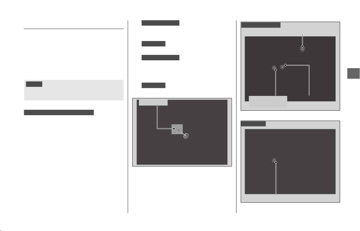
Engine Oil u Changing Engine Oil & Filter
159
Maintenance
Changing Engine Oil & Filter
Changing the oil and filter requires special
tools. We recommend that you have your
vehicle serviced by your dealer.
Use a new Honda Genuine oil filter or
equivalent specified for your model.
Check the engine oil with the Idling Stop
system disabled.
1.
If the engine is cold, idle the engine for
3 to 5 minutes.
2.
Turn the ignition switch OFF and wait
for 2 to 3 minutes.
3.
Place your vehicle on a firm, level
surface.
4.
Place a drain pan
under the drain bolt A, drain bolt B,
drain bolt C and engine oil filter.
Place a drain pan under the
drain bolt and engine oil filter.
5.
Remove the oil fill
cap, drain bolt A, drain bolt B, drain
bolt C and sealing washers to drain the
oil.
Remove the oil fill cap, drain
bolt and sealing washer to drain the oil.
NOTICE
Using the wrong oil filter can result in serious damage
to the engine.
GL1800BD/D/DA Canada model
GL1800BD/D/DA
GL1800/B
GL1800BD/D/DA
GL1800/B
Oil fill cap
Drain bolt A/
sealing washer
Drain bolt B/
sealing washer
Drain bolt C/sealing washer
GL1800BD/D/DA
Drain bolt/sealing washer
GL1800/B
continued
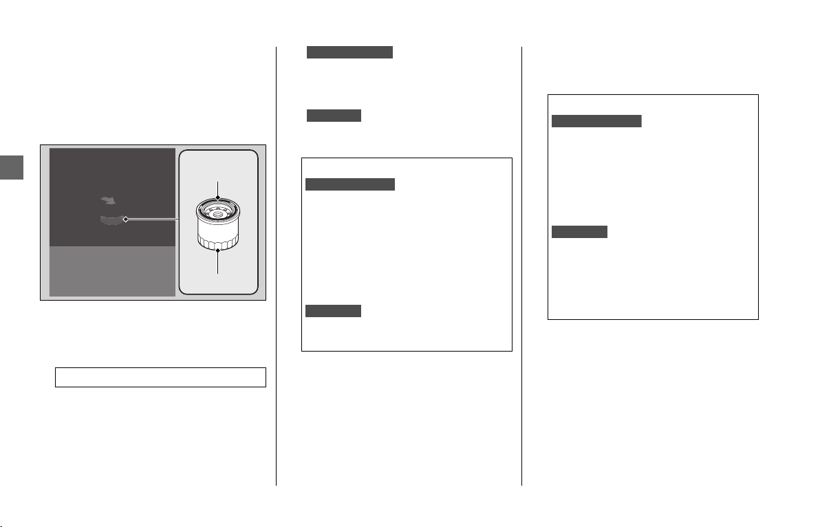
Engine Oil u Changing Engine Oil & Filter
160
Maintenance
6.
Remove the oil filter with a filter
wrench and let the remaining oil drain
out. Make sure the prior seal is not
stuck to the engine.
u Discard the oil and oil filter at an
approved recycling center.
7.
Apply a thin coat of engine oil to the
rubber seal of a new oil filter.
8.
Install the new oil filter and tighten.
9.
Install new sealing
washers onto the drain bolt A, drain
bolt B and drain bolt C. Tighten the
drain bolts to the specified torque.
Install new sealing washer
onto the drain bolt. Tighten the drain
bolt to the specified torque.
10.
Fill the crankcase with the
recommended oil (2 P. 148, 237, 239)
and install the oil fill cap.
11.
Check the oil level. 2 P. 158
12.
Check that there are no oil leaks.
Torque: 19 lbf·ft (26 N·m, 2.7 kgf·m)
Seal
rubber
Oil filter
Torque:
Drain bolt A:
22 lbf·ft (30 N·m, 3.1 kgf·m)
Drain bolt B:
22 lbf·ft (30 N·m, 3.1 kgf·m)
Drain bolt C:
22 lbf·ft (30 N·m, 3.1 kgf·m)
Drain bolt:
22 lbf·ft (30 N·m, 3.1 kgf·m)
GL1800BD/D/DA
GL1800/B
GL1800BD/D/DA:
GL1800/B:
Required oil:
When changing oil & engine oil
filter:
4.9 US qt (4.6 liters)
When changing oil only:
4.6 US qt (4.4 liters)
When changing oil & engine oil
filter:
3.9 US qt (3.7 liters)
When changing oil only:
3.7 US qt (3.5 liters)
GL1800BD/D/DA:
GL1800/B:
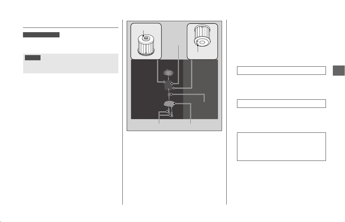
Engine Oil u Changing Clutch Oil Filter
161
Maintenance
Changing Clutch Oil Filter
Use a new Honda Genuine clutch oil filter
or equivalent specified for your model.
1.
Follow the steps 1- 6 of Changing
Engine Oil & Filter.
2 P. 159
2.
Place a drain pan under the clutch oil
filter cover.
3.
Remove the clutch oil filter cover,
spring and clutch oil filter by removing
the oil filter cover bolts.
u Discard the oil and clutch oil filter at
an approved recycling center.
4.
Install a new clutch oil filter with the
rubber seal facing in, toward the
engine. You will see “OUT-SIDE” mark
on the clutch oil filter body, toward the
filter cover.
5.
Replace the O-ring and apply a thin
coat of engine oil to new O-ring before
installing it.
6.
Install the spring and the clutch oil filter
cover.
7.
Install the clutch oil filter cover bolts
and tighten.
8.
Apply a thin coat of engine oil to the
rubber seal of a new engine oil filter.
2 P. 160
9.
Install the new engine oil filter and
tighten.
10.
Replace the sealing washers with new
ones. Install the drain bolts and tighten
them.
2 P. 159
11.
Fill the crankcase with the
recommended oil (
2 P. 148, 237, 239)
and install the oil fill cap.
12.
Check the oil level. (2 P. 158)
13.
Check that there are no oil leaks.
NOTICE
Using the wrong clutch oil filter can result in serious
damage to the transmission.
GL1800BD/D/DA
Oil filter cover/O-ringCover bolts
Clutch
oil filter
Spring
“OUT-SIDE”
Rubber seal
Torque: 19 lbf·ft (26 N·m, 2.7 kgf·m)
Torque: 22 lbf·ft (30 N·m, 3.1 kgf·m)
Required oil:
When changing oil, engine oil
filter & clutch oil filter:
4.9 US qt (4.6 liters)
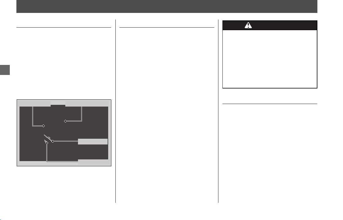
162
Maintenance
Coolant
Checking the Coolant
Check the coolant level in the reserve tank
while the engine is cold.
1.
Place your vehicle on a firm, level
surface.
2.
Remove the left engine side cover. 2 P.
155
3.
Hold your vehicle in an upright position.
4.
Check that the coolant level is between
the UPPER level and LOWER level marks
in the reserve tank.
If the coolant level is dropping noticeably or
the reserve tank is empty, you likely have a
serious leak. Have your vehicle inspected by
your dealer.
Adding Coolant
If the coolant level is below the LOWER
level mark, add the recommended coolant
(
2 P. 149) until the level reaches the UPPER
level mark.
Add fluid only from the reserve tank cap
and do not remove radiator cap.
1.
Remove the left engine side cover. 2 P.
155
2.
Remove the reserve tank cap and add
fluid while monitoring the coolant level.
u Do not overfill above the UPPER level
mark.
u Make sure no foreign objects enter
the reserve tank opening.
3.
Securely reinstall the reserve tank cap.
4.
Install the left engine side cover.
Changing Coolant
Have your dealer change the coolant unless
you have the proper tools and are
mechanically qualified.
UPPER level
Reserve tank
LOWER level
Reserve tank cap
WARNINGWARNING
Removing the radiator cap while the
engine is hot can cause the coolant
to spray out, potentially scalding
you.
Always let the engine and radiator
cool down before removing the
radiator cap.
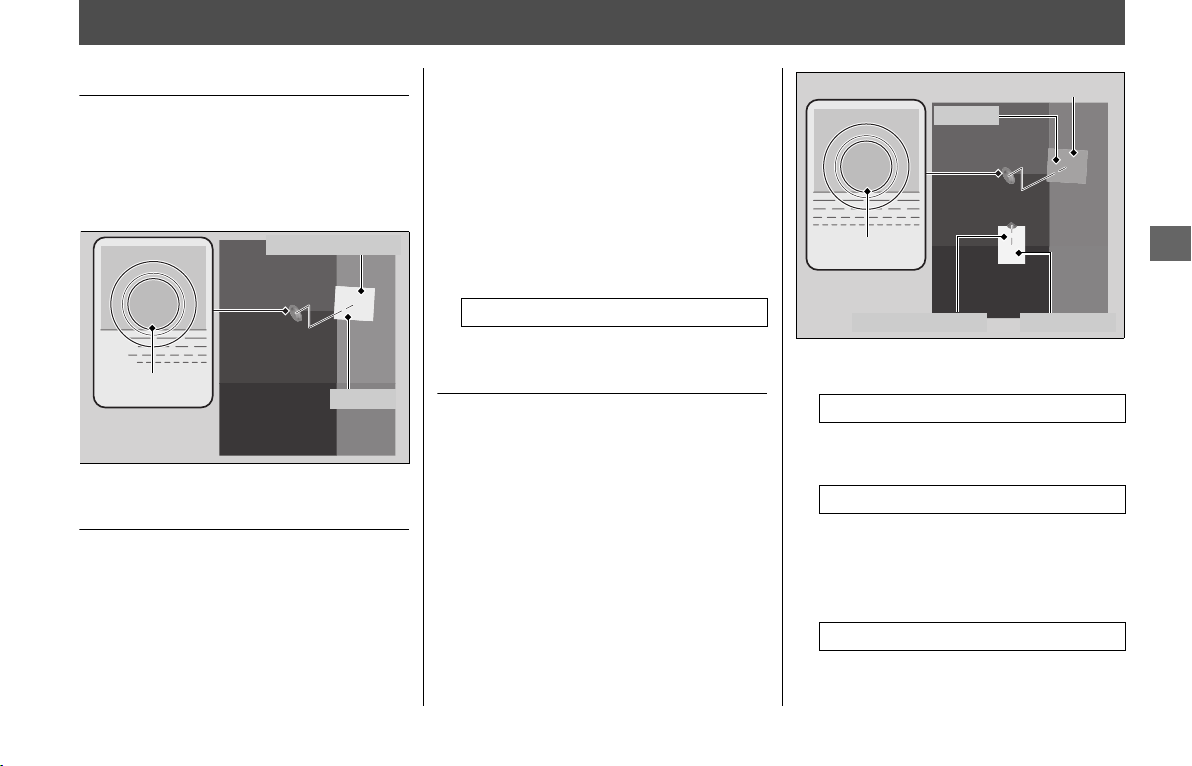
163
Maintenance
Final Drive Oil
Checking the Final Drive Oil
1.
Hold the vehicle upright on firm level
ground.
2.
Remove the oil fill hole cap and O-ring.
3.
Check the oil level. It should be flush
with the lower edge of the oil fill hole.
Adding Final Drive Oil
If the final drive oil level is low, check for oil
leaks. Add the recommended final drive oil
(
2 P. 149) until it reaches the lower edge of
the opening.
1.
Pour the final drive oil into the oil fill
hole until it reaches the lower edge of
the opening.
u Do not over fill above the lower edge
of oil fill hole.
u Make sure no foreign objects enter
the oil fill hole.
u Wipe up any spills immediately.
2.
Install a new O-ring onto the oil fill hole
cap. Tighten the oil fill hole cap.
Changing Final Drive Oil
1.
Hold the vehicle upright on firm level
ground.
2.
Place a drain pan under the drain bolt.
3.
Remove the oil fill hole cap, O-ring,
drain bolt, and sealing washer to drain
the oil.
4.
Install a new sealing washer onto the
drain bolt. Tighten the drain bolt.
5.
Fill the final gear with the recommended
oil. 2 P. 149
6.
Check the oil level. It should be flush
with the lower edge of the oil fill hole.
7.
Install a new O-ring onto the oil fill hole
cap. Tighten the oil fill hole cap.
8.
Check that there are no oil leaks.
Lower edge
Oil fill hole cap
O-ring
Torque: 5.9 lbf·ft (8 N·m, 0.8 kgf·m)
Torque: 9 lbf·ft (12 N·m, 1.2 kgf·m)
Required oil: 4.7 US oz (140 cm
3
)
Torque: 5.9 lbf·ft (8 N·m, 0.8 kgf·m)
Oil fill hole cap
O-ring
Sealing washer Drain bolt
Lower edge
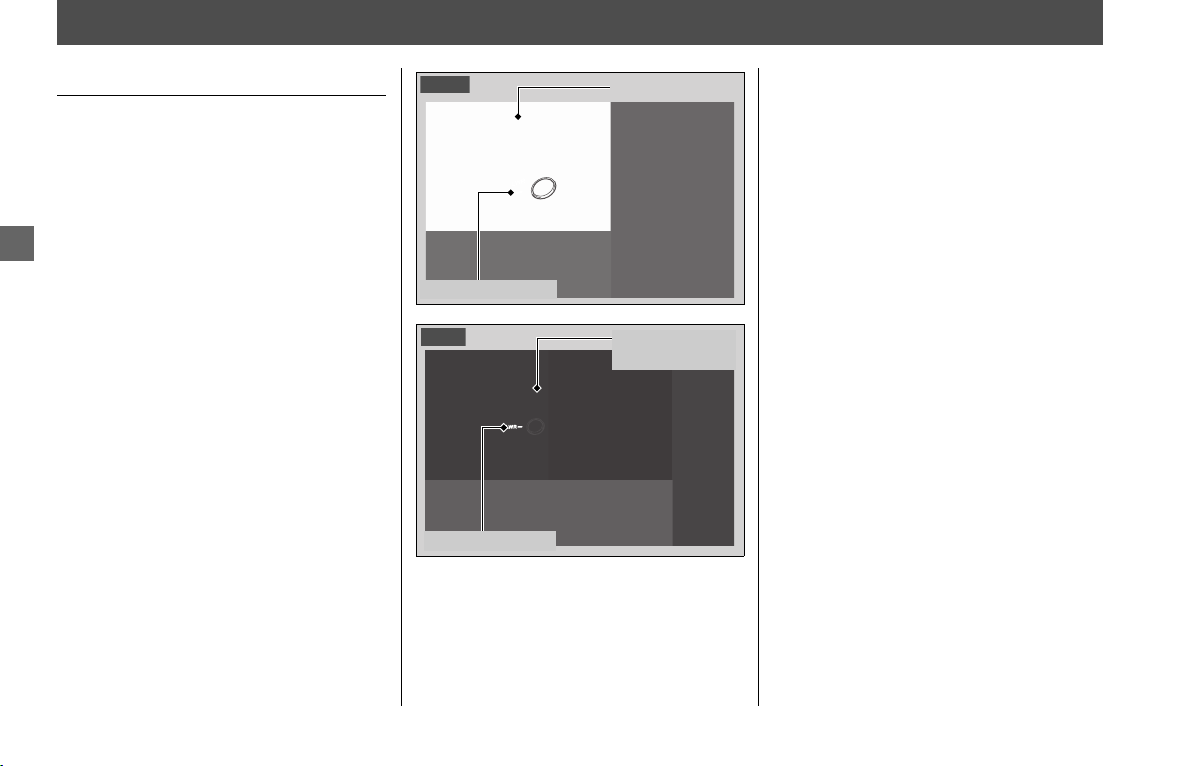
164
Maintenance
Brakes
Checking Brake Fluid
1.
Place your vehicle in an upright position
on a firm, level surface.
2.
Check that the brake fluid reservoir is
horizontal and that the fluid level is
above the LWR mark.
If the brake fluid level in either reservoir is
below the LWR mark or the brake lever and
pedal freeplay becomes excessive, inspect
the brake pads for wear. If the brake pads
are not worn, you most likely have a leak.
Have your vehicle inspected by your dealer.
Front brake
fluid reservoir
LWR level mark
Front
Rear brake
fluid reservoir
LWR level mark
Rear
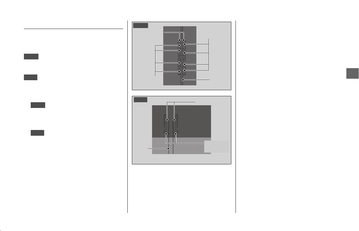
Brakes u Inspecting the Brake Pads
165
Maintenance
Inspecting the Brake Pads
Check the condition of the brake pad wear
indicators.
The pads need to be replaced if a brake pad
is worn to the bottom of the indicator.
The pads need to be replaced if a brake pad
is worn to the indicator.
1.
Inspect the brake pads from in
front of the brake caliper.
u Always inspect both left and right
brake calipers.
2.
Inspect the brake pads from
below the brake caliper.
If necessary have the pads replaced by your
dealer.
Always replace both left and right brake
pads at the same time.
Front
Rear
Front
Rear
Brake pads
Disc
Wear
indicators
Wear
indicators
Front
Brake pads
Disc
Wear
indicator
Rear
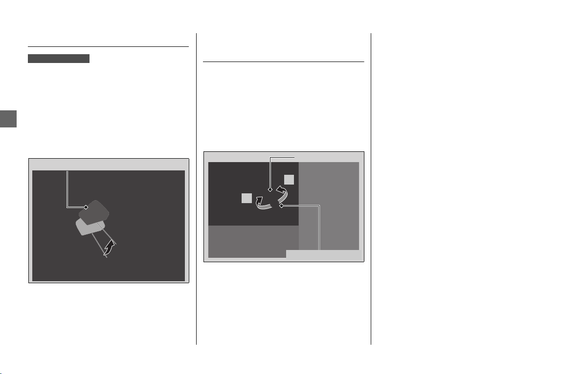
Brakes u Checking the Parking Brake
166
Maintenance
Checking the Parking Brake
Place your vehicle on a firm, level surface.
Stop the engine and push your vehicle
while set the parking brake to check the
efficacy of the parking brake.
If the efficacy of the parking brake
becomes weak, have the brake adjusted by
your dealer.
Adjusting the Brake Light
Switch
Check the operation of the brake light
switch.
Hold the brake light switch and turn the
adjusting nut in the direction A if the switch
operates too late, or turn the nut in the
direction B if the switch operates too soon.
GL1800D/BD/DA
Parking brake lever
Brake light switch
Adjusting nut
B
A

167
Maintenance
Side Stand
Checking the Side Stand
1.
Check that the side stand operates
smoothly. If the side stand is stiff or
squeaky, clean the pivot area and
lubricate the pivot bolt with clean
grease.
2.
Check the spring for damage or loss of
tension.
3.
Sit on the vehicle, shift the transmission
to Neutral, and raise the side stand.
Sit on the vehicle and raise the side
stand.
4.
Start the engine, pull the clutch lever in,
and shift the transmission into gear.
Start the engine and press the D side of
N-D switch to switch the transmission
into AT MODE (D).
5.
Lower the side stand all the way. The
engine should stop as you lower the side
stand. If the engine doesn’t stop, have
your vehicle inspected by your dealer.
Side stand spring
GL1800/B
GL1800D/BD/DA
GL1800/B
GL1800D/BD/DA
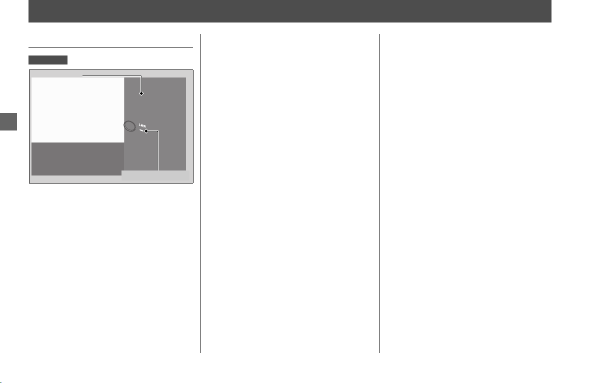
168
Maintenance
Clutch
Checking Clutch Fluid
1.
Place your vehicle in an upright position
on a firm, level surface.
2.
Check that the clutch fluid reservoir is
horizontal and that the fluid level is
above the LWR mark.
If the fluid level is low or if you find fluid
leaks, or deterioration or cracks in the
hoses and fittings, have the clutch system
serviced by your dealer.
GL1800/B
Clutch fluid
reservoir
LWR level mark

169
Maintenance
Throttle
Checking the Throttle
With the engine off, check that the throttle
rotates smoothly from fully closed to fully
open. If the throttle does not move
smoothly, close automatically, have the
vehicle inspected by your dealer.
Throttle
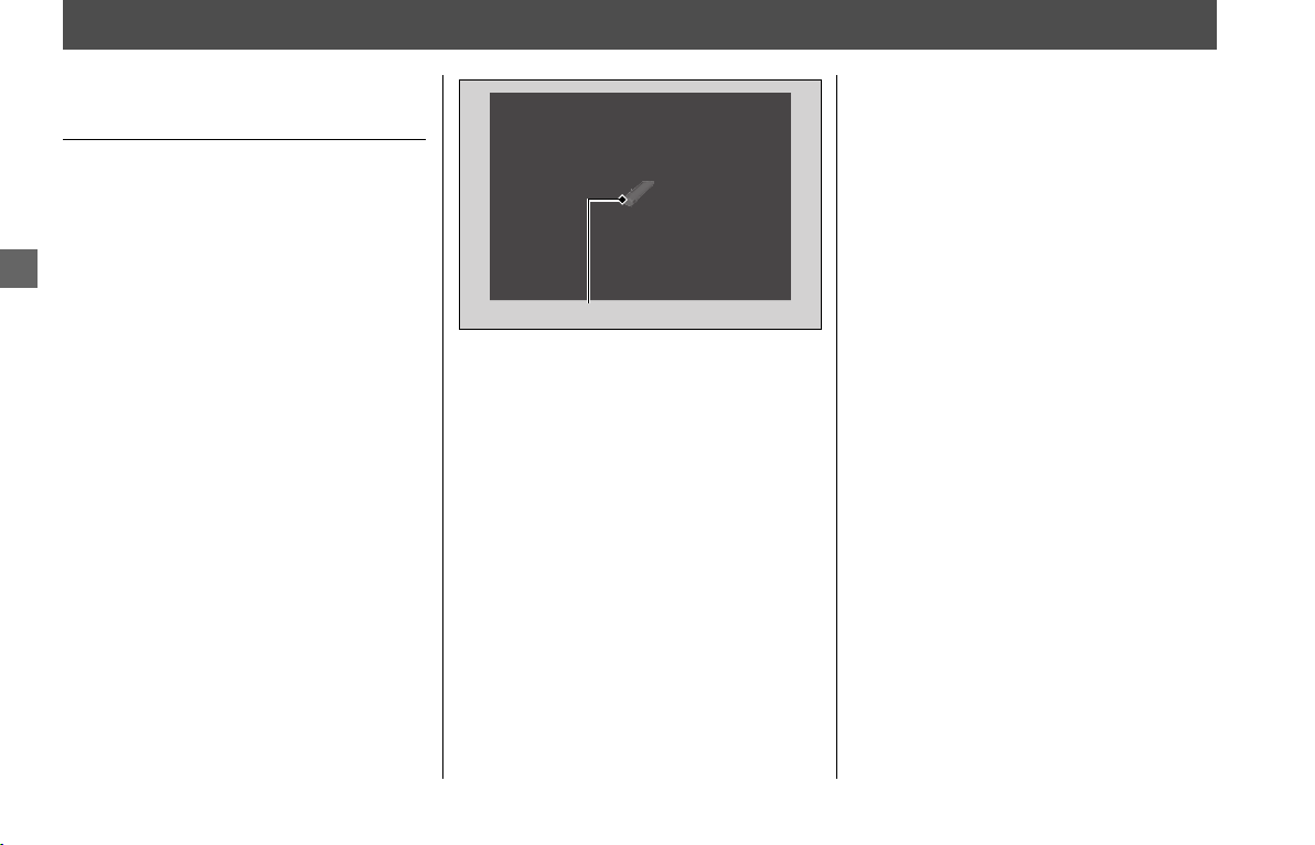
170
Maintenance
Crankcase Breather
Cleaning the Crankcase
Breather
1.
Remove the left fog light cover. 2 P. 155
2.
Remove the left cylinder head side
cover. 2 P. 154
3.
Place a suitable container under the
crankcase breather tube.
4.
Remove the crankcase breather tube
plug from the tube.
5.
Drain deposits into a suitable container.
6.
Install the crankcase breather tube plug.
7.
Install the parts in the reverse order of
removal.
Crankcase breather tube plug
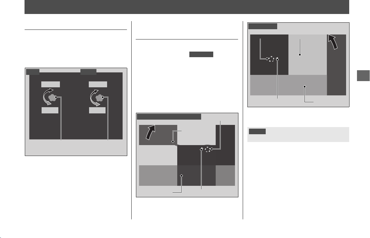
171
Maintenance
Other Adjustments
Adjusting the Headlight Aim
You can adjust vertical aim of the headlight
for proper alignment. Turn the adjusting
knob in or out as necessary.
Obey local laws and regulations.
Adjusting the Clutch and
Brake Levers
You can adjust the distances between the
tip of the clutch lever ( ) and
handle grip, and between the tip of the
brake lever and handle grip.
❙
Adjustment method
Turn the adjuster until the numbers align
with the index mark while pushing the lever
forward in the desired position.
After adjustment, check that the lever
operates correctly before riding.
Right adjusting
knob
LowerLower
RaiseRaise
Left adjusting
knob
Left
Right
GL1800/B
Clutch lever
Forward
Handle grip
Adjuster
Index mark
Clutch lever (GL1800/B only)
NOTICE
Do not turn the adjuster beyond its natural limit.
Adjuster
Brake lever
Handle grip
Index mark
Forward
Brake lever
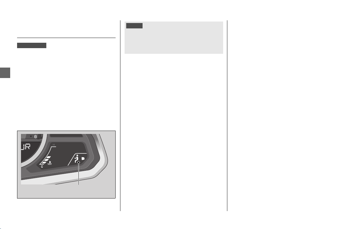
Other Adjustments u Selecting the Electrical Adjustable Suspension
172
Maintenance
Selecting the Electrical
Adjustable Suspension
The electrical adjustable suspension allows
the preload of the rear suspension to be
adjusted in four levels according to riding
and load conditions.
Preload can be adjusted on the multi-
information display.
2 P. 29
When the riding mode is changed, front
and rear suspension damping is
automatically adjusted to a setting
corresponding to the mode.
2 P. 120
GL1800/D/DA
Suspension
preload indicator
NOTICE
The front and rear shock absorber damper units contain
high pressure nitrogen gas. Do not attempt to
disassemble, service, or improperly dispose of the
damper. See your dealer.
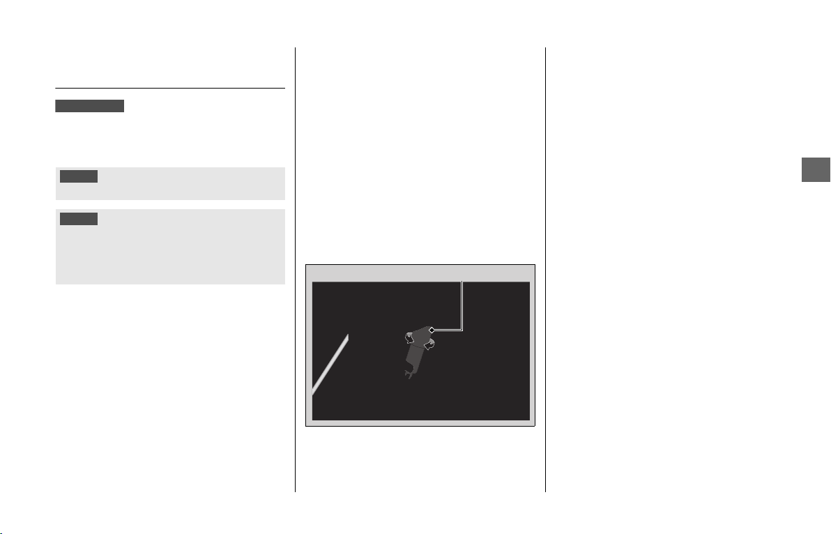
Other Adjustments u Adjusting the Rear Suspension
173
Maintenance
Adjusting the Rear
Suspension
You can adjust the spring preload of the
rear suspension to suit the load or the road
surface.
❙
Spring Preload
Remove the right side cover. 2 P. 156
Turn the adjuster clockwise to increase
spring preload (hard), or turn the adjuster
counterclockwise to decrease spring
preload (soft).
To set the standard position, turn the
adjuster counterclockwise until it will no
longer turn (lightly seat), and then turn the
adjuster clockwise until it clicks. This click is
position 0 (minimum setting). The standard
position is 9 clicks from the minimum
setting (total setting: 33 clicks).
NOTICE
Do not turn the adjuster beyond its limits.
NOTICE
The rear shock absorber damper unit contains high
pressure nitrogen gas. Do not attempt to disassemble,
service, or improperly dispose of the damper. See your
dealer.
GL1800B/BD
Preload adjuster
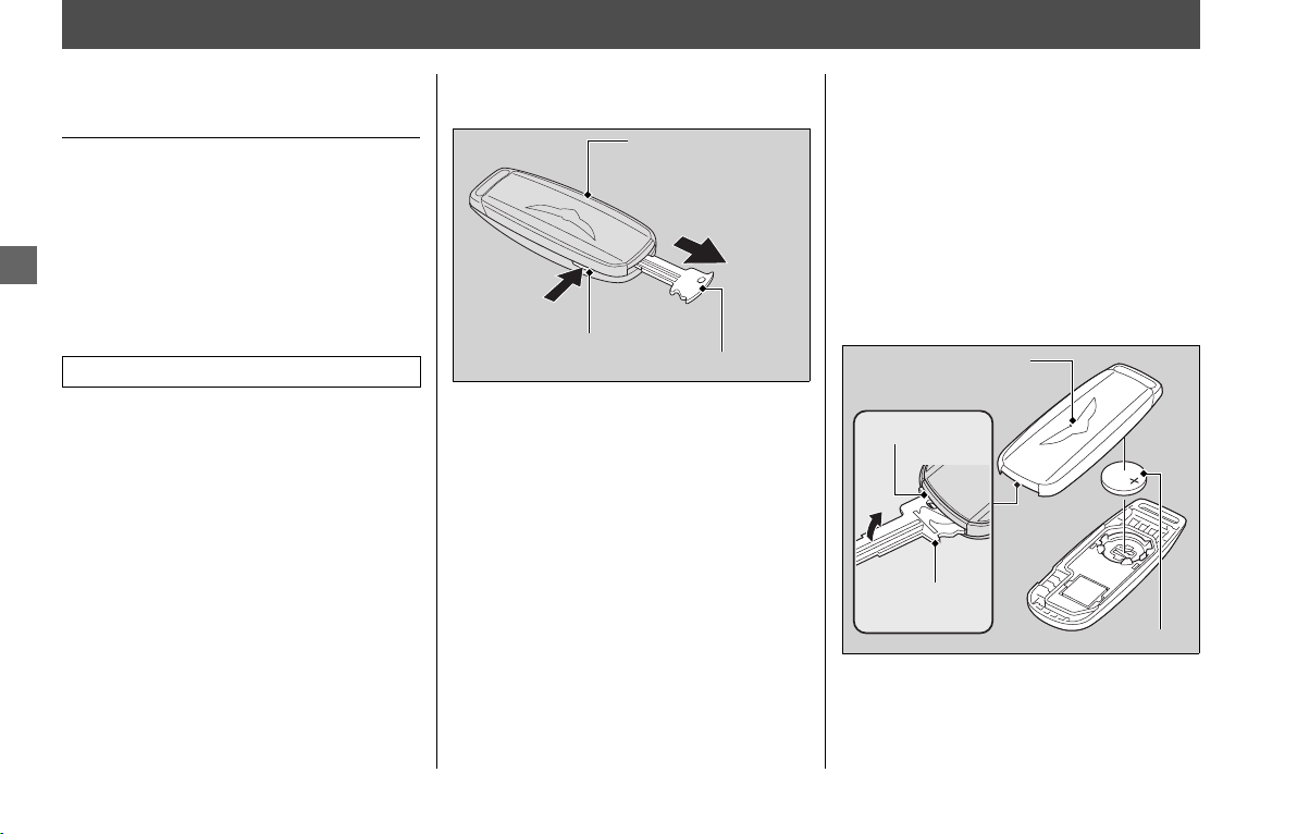
174
Maintenance
Other Replacement
Replacing the Honda SMART
Key Battery
If the Honda SMART Key indicator flashes 5
times when the ignition switch is turned
ON, the low battery pop-up information
appears, or the operating range becomes
unstable, replace the battery as soon as
possible.
We recommend to see your dealer for this
service.
1.
Push the release button and remove the
built-in key from the Honda SMART Key.
2.
Slightly insert the built-in key from the
opposite side into the key hole.
3.
With the emblem upward, separate the
Honda SMART Key by prying the built-in
key as shown in the illustration.
u Do not pry the built-in key forcibly.
u Do not touch the circuit or terminal.
This may cause problems.
u Be careful to avoid scratching the
waterproof covering or allowing dust
to enter.
u Do not forcibly dismantle the Honda
SMART Key body.
Battery type: CR2032
Honda SMART Key
Release button
Built-in key
Emblem
Key hole
Built-in key
Battery
Other Replacement u Replacing the Honda SMART Key Battery
175
Maintenance
4.
Replace the old battery with a new one
with the positive + side facing up.
5.
Assemble the parts in the reverse order
of disassembly.
WARNINGWARNING
Chemical Burn Hazard: do not
swallow battery.
If swallowed, the battery can cause
severe internal burns and even
death.
• Keep battery away from children
and battery compartment
securely closed.
• If the battery compartment does
not close securely, stop using the
product and keep it away from
children.
• Immediately seek medical
attention if a child may have
swallowed battery.

Troubleshooting
Engine Will Not Start........................... P. 177
Overheating (High coolant temperature
indicator is on) ................................... P. 178
Warning Indicators On or Flashing
..... P. 179
Low Oil Pressure Indicator................... P. 179
PGM-FI (Programmed Fuel Injection)
Malfunction Indicator Lamp (MIL) ..... P. 179
Combined ABS Indicator..................... P. 179
Torque Control Indicator
.............................. P. 180
Honda SMART Key Indicator ............... P. 180
Clutch Temperature Indicator
............................... P. 181
Low Tire Pressure Indicator.................. P. 181
TPMS Indicator.................................... P. 182
AIRBAG Indicator .............. P. 182
Other Warning Indications.................. P. 183
Fuel Gauge Failure Indication .............. P. 183
Handle Grip Heater Failure Indication
... P. 183
Seat Heaters Failure Indication
................................... P. 184
Coolant Temperature Gauge Failure Indication
... P. 184
If the “-” is Blinking in the Gear Position Indicator
While Riding (GL1800BD/D/DA)
............ P. 185
When the Idling Stop System Does Not Operate
Properly (GL1800BD/D/DA Canada model)
... P. 186
When the Honda SMART Key System Does
Not Operate Properly ........................ P. 188
Activating the Electrical System in an
Emergency.......................................... P. 189
If the Saddlebags or Travel Trunk Won't Open
... P. 191
Tire Puncture......................................... P. 193
Audio System Trouble.......................... P. 199
Electrical Trouble .................................. P. 207
Battery Goes Dead............................... P. 207
Burned-out Light Bulb ......................... P. 207
Blown Fuse.......................................... P. 209
GL1800/D/DA
GL1800BD/D/DA
GL1800DA
GL1800/D/DA

177
Troubleshooting
Engine Will Not Start
Starter Operates But Engine
Does Not Start
Check the following items:
● Check the correct engine starting
sequence 2 P. 112
● Check that there is gasoline in the fuel
tank
● Check if the PGM-FI (Programmed Fuel
Injection) Malfunction Indicator Lamp
(MIL) is on
u If the indicator lamp is on, contact
your dealer as soon as possible.
Starter Does Not Operate
Check the following items:
● Check the correct engine starting
sequence 2 P. 112
● Check for a blown fuse 2 P. 209
● Check for a loose battery connection
(2 P. 153) or battery terminal corrosion
(2 P. 146)
● Check the condition of the battery
2 P. 207
If the problem continues, have your vehicle
inspected by your dealer.
178
Troubleshooting
Overheating (High coolant temperature indicator is on)
The engine is overheating when the
following occurs:
● High coolant temperature indicator
comes on.
● The 6th (H) segment flashes in the
coolant temperature gauge.
● Acceleration becomes sluggish.
If this occurs, pull safely to the side of the
road and perform the following procedure.
Extended fast idling may cause the high
coolant temperature indicator to come on.
Also the 6th (H) segment will flash.
1.
Stop the engine (2 P. 49), and then turn
the ignition switch to ON.
2.
Check that the radiator fan is operating,
and then turn the ignition switch to OFF.
Suspect a fault. Do not start the engine.
Transport your vehicle to your dealer.
Allow the engine to cool with the
ignition switch turned OFF.
3.
After the engine has cooled, inspect the
radiator hose and check if there is a leak.
2 P. 162
Do not start the engine. Transport your
vehicle to your dealer.
4.
Check the coolant level in the reserve
tank. 2 P. 162
u Add coolant as necessary.
5.
If 1 - 4 check normal, you may continue
riding, but closely monitor the coolant
temperature gauge.
NOTICE
Continuing to ride with an overheated engine can
cause serious damage to the engine.
If the fan is not operating:
If the fan is operating:
If there is a leak:

179
Troubleshooting
Warning Indicators On or Flashing
Low Oil Pressure Indicator
If the low oil pressure indicator comes on,
pull safely to the side of the road and stop
the engine.
1.
Check the engine oil level, and add oil as
necessary. 2 P. 158
2.
Start the engine.
u Only continue riding if the low oil
pressure indicator goes off.
Rapid acceleration may momentarily cause
the low oil pressure indicator to come on,
especially if the oil is at or near the low
level.
If the low oil pressure indicator stays on
when the oil level is at the proper level, stop
the engine and contact your dealer.
If the engine oil level goes down rapidly,
your vehicle may have a leak or another
serious problem. Have your vehicle
inspected by your dealer.
PGM-FI (Programmed Fuel
Injection) Malfunction
Indicator Lamp (MIL)
If the indicator comes on while riding, you
may have a serious problem with the PGM-
FI system. Reduce speed and have your
vehicle inspected by your dealer as soon as
possible.
Combined ABS Indicator
If the Combined ABS indicator operates in
one of the following ways, your brakes will
continue to work as a conventional system,
but without the Combined ABS function.
Reduce your speed and have your vehicle
inspected by your dealer as soon as
possible.
● Indicator does not come on when the
ignition switch is turned ON
● Indicator does not go off at speeds above
3 mph (5 km/h)
● Indicator comes on or starts flashing
while riding
The combined ABS indicator may flash if:
● The front wheel leaves the ground for
1 second or more
● You turn the rear wheel while your
vehicle is lifted off the ground.
This is normal but the Combined ABS is not
in operation. To activate the system again,
turn the ignition switch to OFF, and then to
ON again.
NOTICE
Continuing to ride with low oil pressure can cause
serious damage to the engine.

Warning Indicators On or Flashing u Torque Control Indicator
180
Troubleshooting
Torque Control Indicator
If the indicator operates in one of the
following ways, you may have a serious
problem with the Torque Control. Reduce
your speed and have your vehicle inspected
by your dealer as soon as possible.
● Indicator comes on while riding.
● Indicator does not come on when the
ignition switch is turned on.
● Indicator does not go off at speeds above
3 mph (5 km/h).
Even when the Torque Control indicator is
on, your vehicle will have normal riding
ability without Torque Control function.
u When the indicator comes on while the
Torque Control is in operation, you will
have to completely close the throttle to
regain normal riding ability.
The Torque Control indicator may come on
if you rotate the rear wheel while your
vehicle is lifted off the ground. In this case,
turn the ignition switch to OFF and then ON
again. The Torque Control indicator will go
off after your speed reaches 3 mph (5 km/h).
Honda SMART Key Indicator
❙
If the Honda SMART Key Indicator
Flashes 5 times When the Ignition
Switch is Turned ON
Replacing the Honda SMART Key
Battery 2 P. 174
❙
When the Honda SMART Key
Indicator is Flashing While the
Electrical System is On
The Honda SMART Key indicator flashes
when communication between your
vehicle and Honda SMART Key stops after
turning on the ignition switch.
It is probably caused by the following:
● Strong radio waves or noise are affecting
the system
● You lost the Honda SMART Key while
riding
However, this does not affect the operation
of your vehicle until the ignition switch
turned OFF.
You may not be able to turn off the
electrical system when losing the Honda
SMART Key while riding, or if the battery is
low, or because the system is affected by
strong radio waves or noise. If this occurs,
turn the ignition switch counterclockwise
and hold it until the electrical system shut
off.
If you do not have the Honda SMART Key,
the electrical system can be activated by
means of emergency procedures.
2 P. 189
GL1800/D/DA

Warning Indicators On or Flashing
u
Clutch Temperature Indicator
181
Troubleshooting
Clutch Temperature Indicator
The clutch temperature indicator flashes if
the clutch temperature becomes unusually
high.
If the indicator flashes, pull safely to the
side of the road and shift the transmission
to neutral, then idle the engine.
When the indicator goes off, riding can be
restarted.
If this occurs frequently, contact your
dealer.
Low Tire Pressure Indicator
If the low tire pressure indicator flashes,
check your tires as soon as possible.
If the low tire pressure indicator lights
constantly, one or more of your tires is
significantly underinflated. You should stop
and check your tires as soon as possible.
For more information on temporary repair,
refer to “Emergency Repair Using a Tire
Repair Kit.”
2 P. 193
Check the air pressure when the tires are
cold. (This means the vehicle has been
parked for at least 3 hours.)
Adjust to the recommended tire pressures
if necessary.
2 P. 237, 239
When the low tire pressure indicator
flashes or comes on, but you continue to
ride, the low tire pressure indicator will go
off in some cases. It is still necessary to
check the air pressures of both tires after
the tires cool because air in the tires is
expanded with heat.
If the low tire pressure indicator does not
go off after inflating the tires to the
specified values, have your dealer to check
the system as soon as possible.
Riding on an underinflated tire causes the
tire to overheat and can lead to tire failure.
Under-inflation also reduces fuel efficiency
and tire tread life, and may affect the
vehicle’s handling and stopping ability.
Because tire pressure varies by temperature
and other conditions, the low tire pressure
indicator may turn on unexpectedly.
Please note that the TPMS is not a
substitute for proper tire maintenance, and
it is the rider’s responsibility to maintain
correct tire pressure, even if under-inflation
has not reached the level of turning on the
low tire pressure indicator.
For example, if you check and fill your tires
in a warm area, then ride in extremely cold
weather, the tire pressure will be lower
than measured and could be underinflated
NOTICE
Continuing to ride with high clutch temperature can
cause serious damage to the clutch.
GL1800BD/D/DA
continued
Warning Indicators On or Flashing u TPMS Indicator
182
Troubleshooting
and cause the low tire pressure indicator to
turn on. Or, if you check and adjust your
tire pressure in cooler conditions, and ride
into extremely hot conditions, the tire may
become overinflated. However, the low tire
pressure indicator will not turn on if the
tires are overinflated.
TPMS Indicator
The TPMS indicator comes on if there is a
problem with the tire pressure monitoring
system.
If this occurs, the system will shut off and
no longer monitor tire pressure.
Have the system checked by your dealer as
soon as possible.
Also the TPMS indicator may light for the
following reasons:
● Interference of other electronic devices
by using the same radio frequency.
● Using replacement wheels not equipped
with tire pressure sensors.
AIRBAG Indicator
The AIRBAG indicator comes on if there is a
problem with the airbag system.
If the indicator does not come on, or comes
and stays on when the ignition switch is
turned on, or comes on while you are
riding, have your vehicle inspected by your
dealer as soon as possible as the airbag may
not deploy when it could help save your
life.
Hill Start Assist (HSA)
Indicator
If the Hill start assist (HSA) indicator comes
on in amber in one of the following ways,
you may have a serious problem with the
HSA system.
Reduce speed and have your vehicle
inspected by your dealer as soon as
possible.
● Indicator comes on in amber while riding.
● Indicator does not come on when the
ignition switch is turned to ON.
● Indicator does not go off at speeds above
3 mph (5 km/h).
● Even when the Hill start assist (HSA)
indicator comes on in amber, your
vehicle will have normal riding ability
without HSA function.
If the Hill start assist (HSA) indicator comes
on in white while stopping the vehicle, this
is normal and the HSA is working properly.
WARNINGWARNING
Ignoring the airbag indicator can
result in serious injury or death in a
severe frontal impact if the airbag
system does not work properly.
Have your vehicle checked by a
dealer as soon as possible if the
airbag indicator alerts you to a
possible problem.
GL1800DA
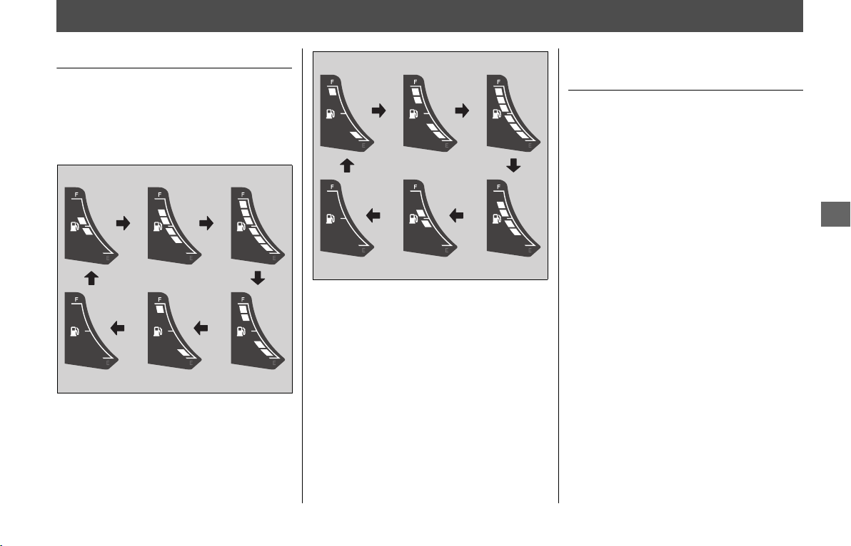
183
Troubleshooting
Other Warning Indications
Fuel Gauge Failure Indication
If the fuel system has an error, the fuel
gauge segments will be displayed as shown
in the illustration.
If this occurs, see your dealer as soon as
possible.
Handle Grip Heater Failure
Indication
If the handle grip heater system has an
error, the handle grip heater indicator will
blink.
If this occurs, see your dealer as soon as
possible.
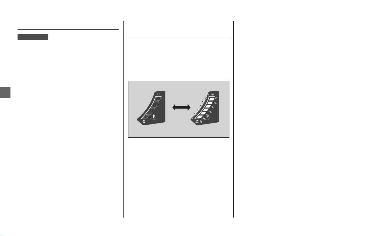
Other Warning Indications u Seat Heaters Failure Indication
184
Troubleshooting
Seat Heaters Failure Indication
If the seat heater system has an error, the
seat heater indicator will blink.
If this occurs, see your dealer as soon as
possible.
Coolant Temperature Gauge
Failure Indication
If the cooling system has an error, all
segments will blink as shown in the
illustration.
If this occurs, see your dealer as soon as
possible.
GL1800/D/DA

185
Troubleshooting
If the “-” is Blinking in the Gear Position Indicator While Riding (GL1800BD/D/DA)
If the “-” is blinking in the gear position
indicator while riding, you may have a
serious problem with the Dual Clutch
Transmission system.
Park your vehicle in a safe place and have
your vehicle inspected by dealer
immediately.
It may be possible to ride your vehicle by
following the steps below.
1.
Turn the ignition switch to OFF.
2.
Turn the ignition switch to ON and start
the engine.
Turn the ignition switch to OFF and move
the vehicle back and forth slightly (to
disengage the gears).
Turn the ignition switch to ON again and
start the engine.
Start the engine while applying the brake
lever or pressing the brake pedal.
When a gear position is shown in the gear
position indicator, you can ride in that gear.
Take your vehicle to your dealer riding at a
safe speed.
Possible damage to the DCT is preventing
you from riding.
Have your vehicle inspected by your dealer
immediately.
If you cannot start the engine:
If you still cannot start the engine:
If you can shift from N to D range:
If you can't shift from N to D range and
the “-” is blinking:
186
Troubleshooting
When the Idling Stop System Does Not Operate Properly (GL1800BD/D/DA Canada model)
Idling Stop Indicator Does Not
Come On
When the Idling Stop indicator does not
come on, perform the followings.
Press the start/Idling Stop button or set the
Idling Stop system at the multi-information
display.
Warm up the engine.
The Idling Stop system does not operate
when the engine is cold.
Ride the vehicle at speeds of over 6 mph
(10 km/h). The Idling Stop system does not
operate until you ride once.
When the PGM-FI malfunction indicator
lamp (MIL) lights, the Idling Stop system
does not operate for protection of the
engine. See your dealer.
Ride the vehicle for a while, then stop the
engine and then restart the engine,
referring to the correct engine starting
procedure (
2 P. 112). The Idling Stop
system may not operate if the battery
voltage is low.
If this occurs frequently, contact your
dealer.
Ride the vehicle for a while.
The Idling Stop system does not operate
when the battery is cold.
Engine is Not Stopped by the
Idling Stop System While the
Idling Stop Indicator is On
When the engine is not stopped by Idling
Stop system while the Idling Stop indicator
is on, perform the following.
Stop the vehicle completely. The Idling Stop
system operates if the speed is only at 0
mph (0 km/h).
Close the throttle completely.
The Idling Stop system does not stop the
engine while the HSA is operated.
The Idling Stop system does not stop the
engine when the transmission is shifted in
Neutral (N side of the N-D switch is
pressed).
If the Idling Stop system is off:
If the engine is cold:
If you did not ride the vehicle after engine starts:
If PGM-FI malfunction indicator lamp (MIL) lights:
If the battery voltage is low:
If the temperature of the battery is cold:
If the vehicle does not stop completely:
If the throttle is not closed completely:
If the Hill start assist (HSA) is operated:
When the transmission is shifted in Neutral:

When the Idling Stop System Does Not Operate Properly (GL1800BD/D/DA Canada model)
u
Engine Does Not Start Even If the Throttle is Opened
187
Troubleshooting
Engine Does Not Start Even If
the Throttle is Opened
Engine does not start even if the throttle is
opened, perform the followings.
While the engine is stopped by the Idling
Stop system, if you operate the side stand,
the flashing Idling Stop indicator changes
flashing to off, and the Idling Stop system is
cancelled. Restart the engine with the start/
Idling Stop button, referring to the starting
procedure (
2 P. 112) for standard engine
starting.
When the rider has not been sitting astride
the vehicle for approx. 3 minutes, the Idling
Stop indicator changes from flashing to off
and you cannot restart the engine, even if
you open the throttle.
Restart the engine with the start/Idling Stop
button, referring to the starting procedure
for standard engine starting.
While the engine is stopping by the Idling
Stop system, if you press the start/Idling
Stop button, the Idling Stop system will be
cancelled.
Restart the engine with the start/Idling Stop
button, referring to the starting procedure
(
2 P. 112) for standard engine starting.
If the Idling Stop indicator flashes, but
engine does not start even if the throttle is
opened, perform the followings.
Check the battery terminals.
If the side stand is down:
If the rider does not sit astride the vehicle:
If the start/Idling Stop button is operated:
Battery lead is loose:

188
Troubleshooting
When the Honda SMART Key System Does Not Operate Properly
When the Honda SMART Key system does
not work properly, perform the following.
● Check that the Honda SMART Key
system is activated.
Lightly press the ON/OFF button on the
Honda SMART Key.
If the LED of the Honda SMART Key does
not blink 3 times, switch the Honda
SMART Key system to activation.
2 P. 56
If the LED of the Honda SMART Key does
not respond, replace the battery of the
Honda SMART Key.
2 P. 174
● Check that there is no communication
failure in the Honda SMART Key system.
The Honda SMART Key system uses low-
intensity radio waves. The Honda SMART
Key system may not work properly in the
following environments:
u When there are facilities nearby that
generate strong radio waves or noise
such as TV towers, power stations,
radio stations, or airports.
u When you carry the Honda SMART
Key with a laptop or wireless
communication device such as a radio
or mobile phone.
u When the Honda SMART Key comes
into contact with or is covered by
metal objects.
● Check that a registered Honda SMART
Key is used.
Use a registered Honda SMART Key.
The Honda SMART Key system cannot be
activated without a registered Honda
SMART Key.
● Make sure that you do not use a broken
Honda SMART Key.
If you use a broken Honda SMART Key,
the Honda SMART Key system cannot be
activated. Bring the emergency key and
ID tag to your dealer.
● Check the battery condition and battery
lead in your vehicle.
Check the battery and battery terminals.
If the battery is weak, contact your
dealer.
If the Honda SMART Key system cannot be
activated due to other causes, contact your
dealer.
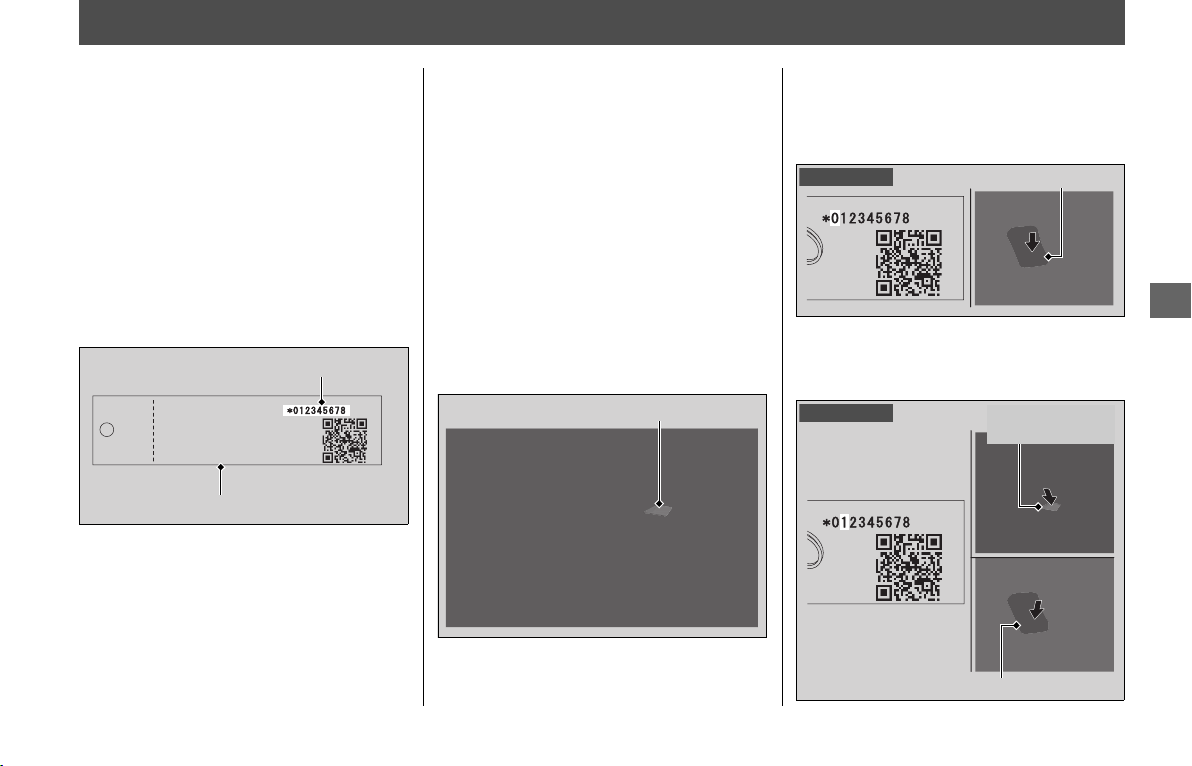
189
Troubleshooting
Activating the Electrical System in an Emergency
The electrical system can be activated by
inputting the ID number.
❙
Set to ID number input mode
1.
Open the left and right saddlebags by
the emergency procedures. 2 P. 191
2.
Press and hold the start button for more
than 4 seconds.
u The buzzer sounds and the system
enters the ID number input mode.
3.
Check the ID number on the ID tag.
❙
ID number input
You can input your ID number by pressing
the fairing pocket opener and the start
button. Input the ID number on the ID tag
starting with the digit on the left by
pressing the fairing pocket opener.
The ID number is input according to the
number of times the fairing pocket opener
is pressed.
Press the fairing pocket opener the desired
number of times, then press the start
button to fix the current digit (the buzzer
sounds), and input the next digit, and then
repeat until all the digits are input.
While inputting the ID number, if the
button is not pressed for about 20 seconds,
the inputted ID number is cancelled and the
system returns to the state before ID
number input (the buzzer sounds).
Example:
• To input “0”, press the start button
without pressing the fairing pocket
opener, and then input next digit.
• To input “1”, press the fairing pocket
opener once, and then press the start
button to input the next digit.
ID tag
ID number
Fairing pocket opener
To input “0”
Start button
To input “1”
Fairing pocket
opener
Start button
continued

Activating the Electrical System in an Emergency
190
Troubleshooting
ID number input success:
After the last digit of the ID number is
inputted and the start button is pressed,
the ID number is authenticated. The
steering will be unlocked (if it is locked) and
the electrical system activated.
You can start the engine.
You can turn off the engine and electrical
system and also lock the steering using the
ignition switch.
To activate the electrical system again,
repeat the procedures for ID number input.
ID number input failure:
If the ID number is not authenticated after
inputting, the steering cannot be unlocked
and the electrical system will not activate.
Repeat the procedures for ID number input
from the beginning.
ID number input cancel
If you input the wrong number, you can
cancel ID number input by not pressing the
button for about 20 seconds (the buzzer
sounds).
Repeat the procedures for ID number input
from the beginning.
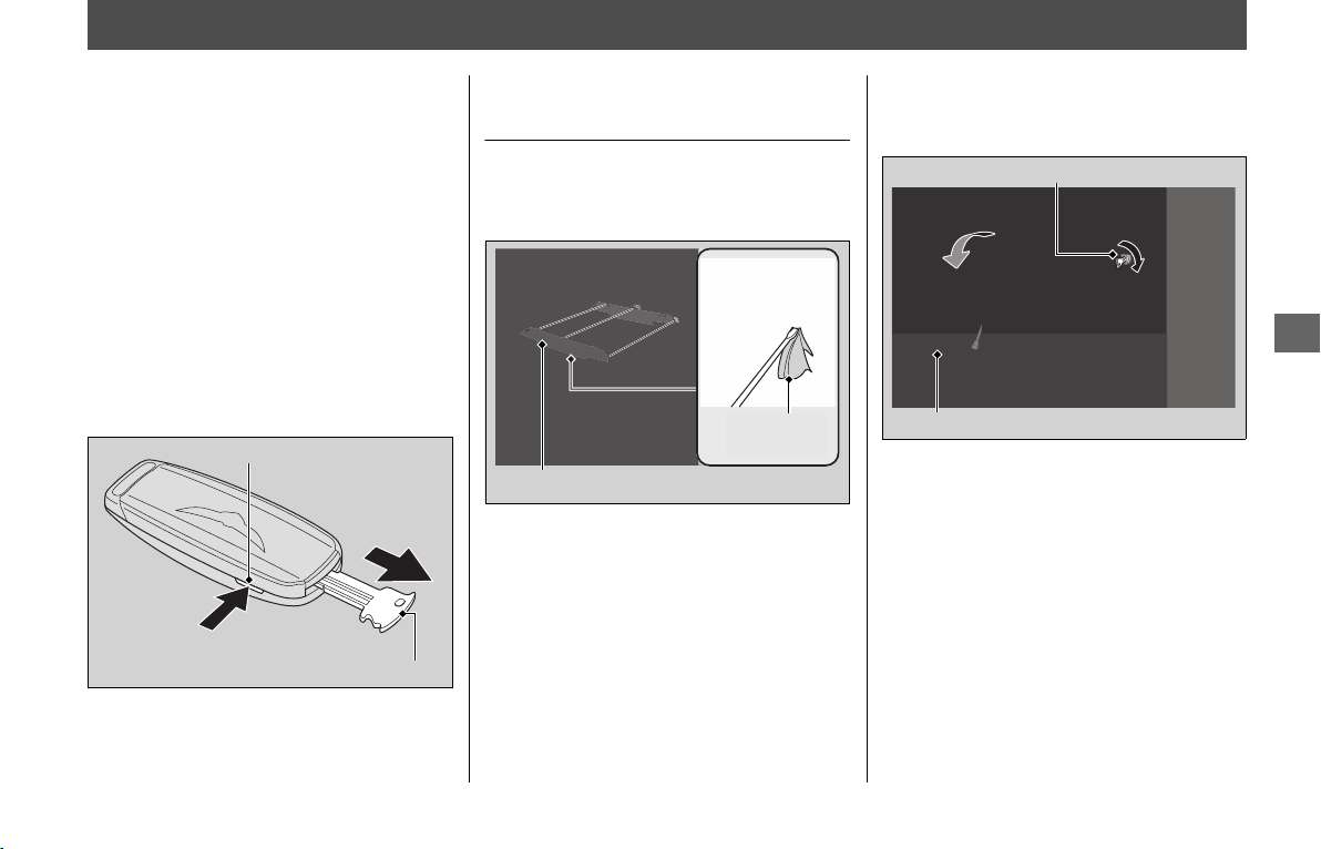
191
Troubleshooting
If the Saddlebags or Travel Trunk Won't Open
The built-in key can be used to open the
left saddle bag when the Honda SMART
Key battery becomes weak.
If you lose the Honda SMART Key, the left
saddlebag can be unlocked using the
emergency key.
2 P. 212
To remove the built-in key, pull it out by
pressing the release button on the Honda
SMART Key.
To reinstall the built-in key, push the built-
in key into the Honda SMART Key until it
clicks.
To Open the Saddlebags
Emergency
1.
Remove the rear center lid by using a flat
head screwdriver covered with a
protective cloth.
2.
Remove the built-in key from the Honda
SMART Key.
3.
Insert the built-in key or emergency key
in the left saddlebag opener and turn it
clockwise to open the left saddlebag.
Release button
Built-in key
Protective
cloth
Rear center lid
Left saddlebag opener
Left saddlebag lid
continued
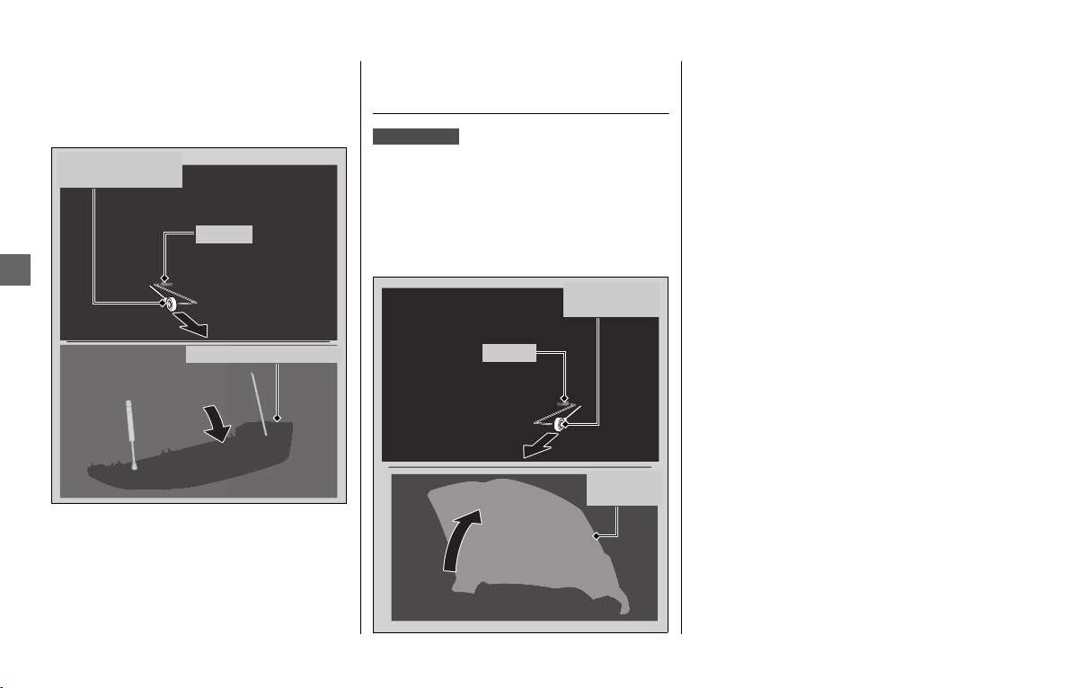
If the Saddlebags or Travel Trunk Won't Open u To Open the Travel Trunk Emergency
192
Troubleshooting
4.
Release the right saddlebag opener from
the prong in the left saddlebag. Pull the
right saddlebag opener to open the
right saddlebag.
5.
Install the right saddlebag opener onto
the prong before closing the
saddlebags.
To Open the Travel Trunk
Emergency
1.
Open the left and right saddlebags.
2 P. 191
2.
Release the travel trunk opener from the
prong in the right saddlebag. Pull the
travel trunk opener to open the travel
trunk.
3.
Install the travel trunk opener onto the
prong before closing the right
saddlebag.
Right saddlebag lid
Right saddlebag
opener
Prong
GL1800/D/DA
Travel trunk
opener
Travel
trunk lid
Prong
193
Troubleshooting
Tire Puncture
Repairing a puncture or removing a wheel
requires special tools and technical
expertise.
We recommend you have this type of
service performed by your dealer.
After an emergency repair, always have the
tire inspected/replaced by your dealer.
Emergency Repair Using a Tire
Repair Kit
If your tire has a minor puncture, you can
make an emergency repair using a tubeless
tire repair kit.
Follow the instructions provided with the
emergency tire repair kit.
Riding your vehicle with a temporary tire
repair is very risky. Do not exceed 30 mph
(50 km/h). Have the tire replaced by your
dealer as soon as possible.
Removing Wheels
Follow these procedures if you need to
remove a wheel in order to repair a
puncture.
When removing and installing the wheel,
be careful not to damage the wheel speed
sensor and pulser ring.
NOTICE
Using a puncture-repairing agent can damage the
TPMS sensors, causing the TPMS indicator to turn on.
Have your vehicle checked by your dealer as soon as
possible.
NOTICE
Use caution not to damage the TPMS sensor if an
internal plug patch must be used to repair the tire. If
you have a tire professionally repaired at a non-Honda
facility, we recommend that you have the work
checked by your dealer. TPMS wheels require special
handling when changing the tire. Failure to follow the
proper tire replacement procedure can result in
damage to the TPMS sensor.
WARNINGWARNING
Riding your vehicle with a temporary
tire repair can be risky. If the
temporary repair fails, you can crash
and be seriously injured or killed.
If you must ride with a temporary
tire repair, ride slowly and carefully
and do not exceed 30 mph (50 km/h)
until the tire is replaced.
continued
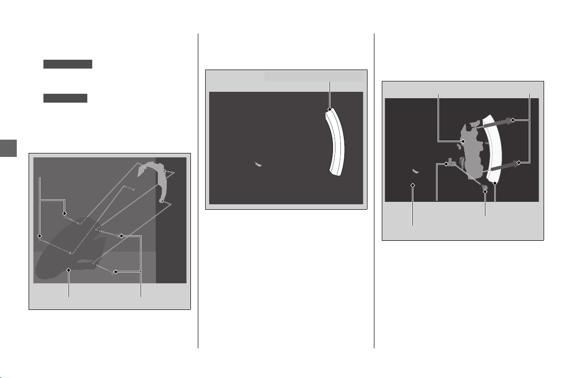
Tire Puncture u Removing Wheels
194
Troubleshooting
❙
Front Wheel
Removal
1.
Place your vehicle on its center stand
on a firm, level surface.
Place your vehicle on a firm, level
surface.
2.
Remove the bolts, and then remove the
front fender A forward.
3.
Cover both sides of the front wheel
and brake calipers with protective tape
or cloth.
4.
Remove the bolt and wheel speed
sensor.
5.
On the left side, remove the mounting
bolts and remove the brake caliper.
GL1800/D/DA
GL1800B/BD
Front fender A Bolts
Bolts
Protective tape or cloth
Wheel speed
sensor
Brake caliper
Mounting bolts
Tape or cloth
Pulser ring
Wheel speed
sensor bolt
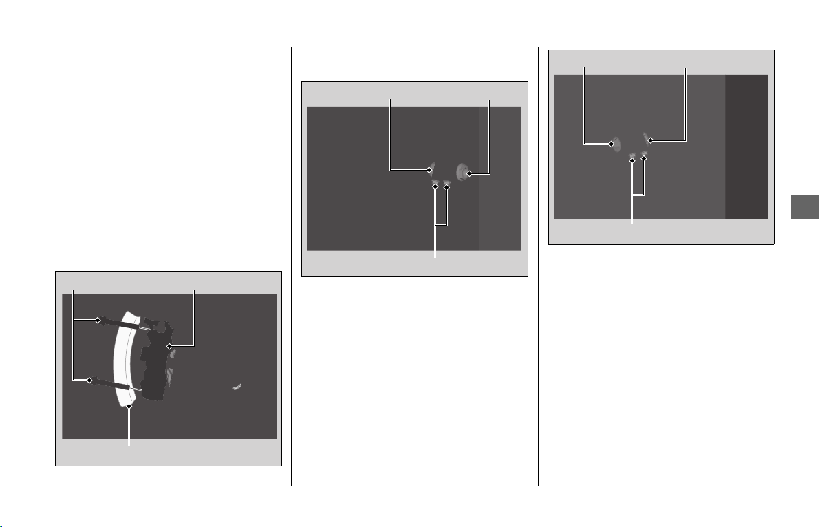
Tire Puncture
u
Removing Wheels
195
Troubleshooting
6.
On the right side, remove the
mounting bolts and remove the brake
caliper.
u Support the brake caliper assembly
so that it doesn't hang from the
brake hose. Do not twist the brake
hose.
u Avoid getting grease, oil, or dirt on
the disc or pad surfaces.
u Do not pull the front brake lever
while the brake caliper is removed.
u Take care to prevent the brake
caliper from scratching the wheel
during removal.
7.
Remove the front axle bolt.
8.
Loosen the left axle pinch bolts.
9.
Support your vehicle securely and raise
the front wheel off the ground using a
maintenance stand or a hoist.
10.
Loosen the right axle pinch bolts.
11.
On the right side, withdraw the front
axle shaft, and remove the side collars
and front wheel.
Installation
1.
Attach the side collars to the front
wheel.
2.
On the right side, place the front wheel
between the fork legs and insert the
lightly greased front axle shaft to the
end, through the right fork leg and
wheel hub.
3.
Align the end of the front axle shaft
with the surface of the fork leg.
4.
Tighten the right axle pinch bolts to
hold the axle.
Mounting bolts Brake caliper
Tape or cloth
Left axle pinch bolts
Left side collar
Front axle bolt
Right axle pinch bolts
Right side collarFront axle shaft
continued
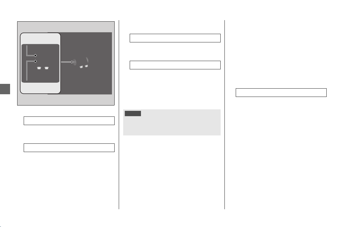
Tire Puncture u Removing Wheels
196
Troubleshooting
5.
Install and tighten the axle bolt.
6.
Loosen the right axle pinch bolts.
7.
Tighten the left axle pinch bolts.
8.
Install the right brake caliper and
tighten the mounting bolts.
9.
Install the left brake caliper and tighten
the mounting bolts.
u Take care to prevent the brake
caliper from scratching the wheel
during installation.
u Use new mounting bolts when
installing the brake caliper.
10.
Install the wheel speed sensor and
tighten the bolt securely.
11.
Lower the front wheel on the ground.
12.
Apply the brake lever and pedal several
times. Then, pump the fork several
times.
13.
Make sure the end of the front axle
shaft align with the surface of the right
fork leg.
Retighten the right axle pinch bolts.
14.
Raise the front wheel off the ground
again, and check that the wheel
rotates freely after you release the
brake.
15.
Uncover the protective tape or cloth.
16.
Install the front fender A and tighten
the bolts securely.
If a torque wrench was not used for
installation, see your dealer as soon as
possible to verify proper assembly.
Improper assembly may lead to loss of
braking capacity.
Torque: 44 lbf·ft (59 N·m, 6.0 kgf·m)
Torque: 16 lbf·ft (22 N·m, 2.2 kgf·m)
Surface of
fork leg
End of front
axle shaft
Torque:
31 lbf·ft (42.5 N·m, 4.3 kgf·m)
Torque:
31 lbf·ft (42.5 N·m, 4.3 kgf·m)
NOTICE
When installing a wheel or caliper into original
position, carefully fit the brake disc between the pads
to avoid scratching them.
Torque: 16 lbf·ft (22 N·m, 2.2 kgf·m)
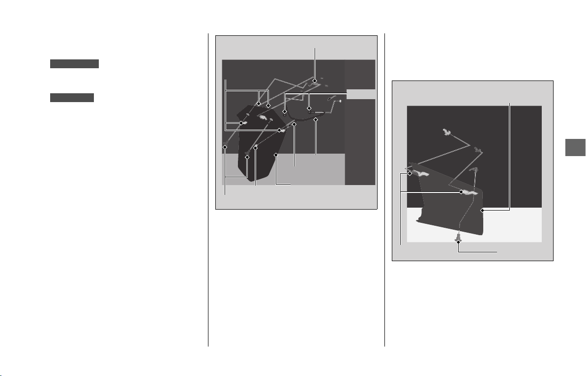
Tire Puncture
u
Removing Wheels
197
Troubleshooting
❙
Rear Wheel
Removal
1.
Place your vehicle on its center stand on
a firm, level surface.
Place your vehicle on a firm, level
surface.
2.
Remove the bolts A and pull out the rear
fender A while releasing the tabs from
the slots and the prong from the
grommet.
3.
Remove the rear fender A, then
disconnect the connector.
4.
Remove the bolts B and rear cross pipe.
5.
Remove the bolt C and pull the left
muffler inner cover forward to release
the hooks.
6.
Remove the left muffler inner cover.
GL1800/D/DA
GL1800B/BD
Rear fender A
Bolts A
Tabs
Prong
Grommet
Connector
Bolts B
Rear cross pipe
Bolt C
Hooks
Left muffler
inner cover
continued
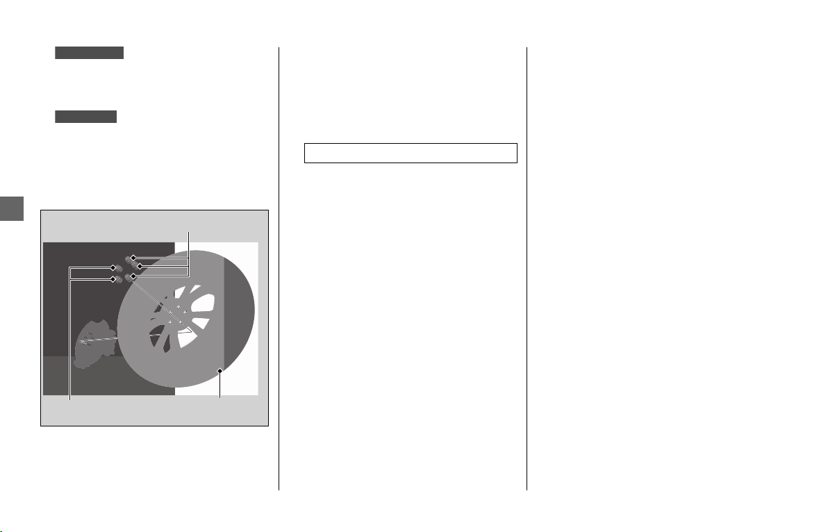
Tire Puncture u Removing Wheels
198
Troubleshooting
7.
Support your vehicle securely and raise
the rear wheel off the ground using the
center stand or a hoist.
Support your vehicle securely and raise
the rear wheel off the ground using a
maintenance stand or a hoist.
8.
Remove the rear wheel nuts, and
remove the rear wheel.
Installation
1.
To install the rear wheel, reverse the
removal procedure.
2.
Install the rear wheel and tighten the
rear wheel nuts equally in the crisscross
pattern in two or three steps.
3.
Install the parts in the reverse order of
removal.
4.
Check that the wheel rotates freely.
If a torque wrench was not used for
installation, see your dealer as soon as
possible to verify proper assembly.
Improper assembly may lead to loss of
braking capacity.
GL1800/D/DA
GL1800B/BD
Rear wheel nuts
Rear wheel nuts Rear wheel
Torque:
80 lbf·ft (108 N·m, 11.0 kgf·m)
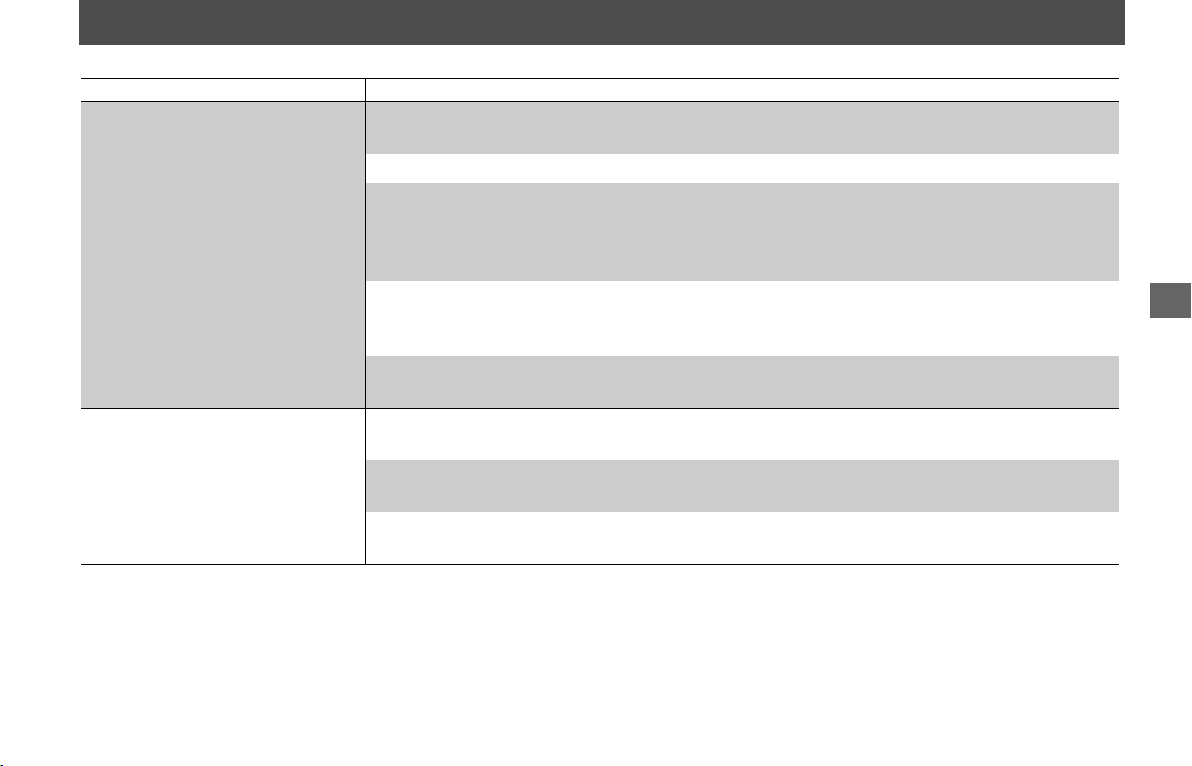
199
Troubleshooting
Audio System Trouble
Symptom Cause/remedy
Unable to pair Bluetooth
®
device
Some Bluetooth
®
devices and application software you use may be incompatible with the audio
system and/or the operable functions may be limited.
Check that the audio system and Bluetooth
®
device are both in the pairing mode. 2 P. 83, 88
The audio system may not be properly connected when another Bluetooth
®
device is being paired
at the same time. Check your surroundings to make sure no other device being paired is present
before re-pairing. Presence of a Bluetooth
®
device in the vicinity sometimes affects the pairing due
to radio wave interference, etc.
When connecting a Bluetooth
®
device, make sure no other Bluetooth
®
device readied for pairing
is present. Presence of a Bluetooth
®
device in the vicinity sometimes affects the pairing due to
radio wave interference, etc.
When you repeatedly fail in pairing, delete the paired device once, then try pairing again.
2 P. 83, 86
Unable to connect Bluetooth
®
device
Depending on the Bluetooth
®
device and application software you use, it may take some time for
the audio system to connect to a device and to start playing an audio file.
The connection may be temporarily disconnected when starting the engine, which is normal and
not a malfunction. The Bluetooth
®
device will be reconnected after the engine is started.
Check that your Bluetooth
®
device has been paired. Referring to the instruction manual of your
Bluetooth
®
device, check that your Bluetooth
®
device is in connectable state.
continued
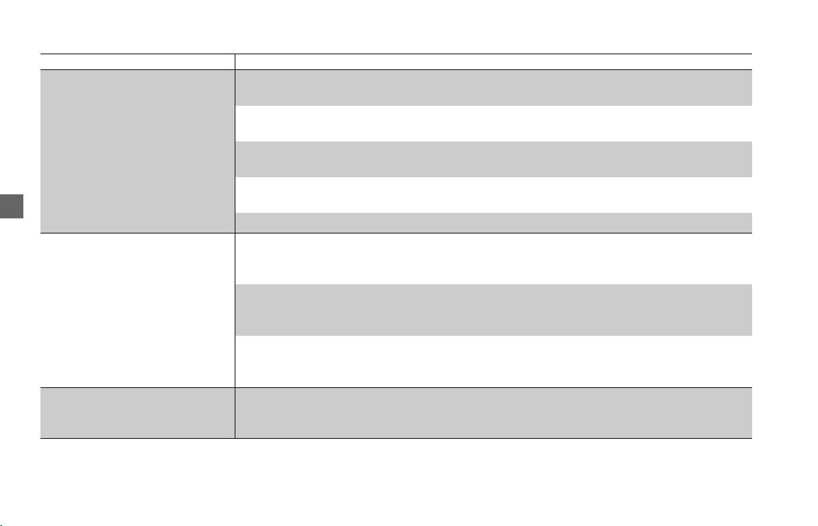
Audio System Trouble
200
Troubleshooting
Symptom Cause/remedy
Unable to connect Bluetooth
®
phone device
Some Bluetooth
®
devices and application software you use may not connect automatically. For
connecting, follow the instructions in the instruction manual of your Bluetooth
®
device.
The Bluetooth
®
devices that can be connected at the same time are limited to one Bluetooth
®
device and two Bluetooth
®
headsets.
If the problem continues after the above-described inspection, delete the paired device once, then
try pairing again. 2 P. 83, 86, 88
The Bluetooth
®
connection cannot be established while launching Apple CarPlay. Quit Apple
CarPlay, then try pairing again.
2 P. 83, 86
While connected to Apple CarPlay, Bluetooth function is disabled.
Connected, but does not play.
Some Bluetooth
®
devices and application software you use may be incompatible with the audio
system and/or audio files may not be played properly. Check the recommended specifications.
2 P. 82
Depending on the Bluetooth
®
device and application software you use, an audio file may not play
automatically. For playing, follow the instructions in the instruction manual of your Bluetooth
®
device.
Depending on the Bluetooth
®
device and application software you use, an audio file may not play
normally after receiving a telephone call, etc. Check that your Bluetooth
®
device is in playable
state.
Takes some time to start playing
after turning the power on or
changing the audio mode.
Right after the power is turned on or the audio mode is changed, the audio system may take some
time to connect to an audio device and to start playing an audio file. Also, the audio system may
not allow any audio control operation while preparing to play an audio file.

Audio System Trouble
201
Troubleshooting
Symptom Cause/remedy
Sounds skip
Noises mix
Presence of another Bluetooth
®
device or a device that emits electromagnetic waves such as
communication equipment in the vicinity sometimes affects the communication.
Due to the characteristics of Bluetooth
®
, though in rare cases, the system operation may become
unstable. When it remains unstable, turn off the power to the audio system or the device being
used, and then turn it on again.
The storage location of the Bluetooth
®
device sometimes affects the audio system and
communication. When sounds skip or noises mix, change the location of the device. For example,
when the device is kept in a pocket of clothing sandwiched in between the rider and passenger,
the communication may be affected. For Bluetooth
®
antenna locations, refer to Audio System
Location. 2 P. 68
Also, weather, buildings in the vicinity, road conditions, etc. can sometimes affect the
communication.
Depending on the Bluetooth
®
device and application software you use, an audio file may not play
normally after receiving a telephone call, etc. Change the audio mode (
2 P. 71) or turn off the
power to the audio system and then turn it on again. If the skipping of sounds or mixing of noises
continues, check the status of your Bluetooth
®
device.
If the skipping of sounds or mixing of noises continues, delete the paired device once, then try
pairing again. 2 P. 83, 86
Check the recommended specifications.
2 P. 82
Noise sometimes mixes at the place where radio wave is weak.
Audio volume from headset is
small/big.
Adjust the volume while in the individual modes.
2 P. 71
Check the volume setting of the paired headset.
continued
Audio System Trouble
202
Troubleshooting
Symptom Cause/remedy
No or inaccurate display
Depending on the audio device and the audio file, nothing may be displayed or the display may
be inaccurate in some cases. Check the information on available tags.
2 P. 95
When the information in an audio file such as the artist name and track title is in a non-compliant
tag format, it may be indicated by “.” or no information will be shown.
Depending on the type of the album art used for the music information of audio files, the album
art may not be displayed. The system supports ID3v2 as available tag for album art. Check the
album art format of the audio file.
The system does not support album art display via Bluetooth
®
connection.
About USB device
Some USB devices may be incompatible with the audio system and/or their operable functions
may be limited.
When the audio system does not recognize the USB device connected to the USB connector, turn
the ignition switch OFF and then turn it on again.
When a large number of files are stored in the USB device, it sometimes takes a long time before
an audio file starts playing. Reduce the number of files in the USB device.
Check that the audio files stored in the USB device is in a playable file format.
2 P. 95
USB failure
USB function may be unusable when the system failure occurs. USB connection may recover by
turning the ignition switch OFF, and then ON again.
Audio System Trouble
203
Troubleshooting
Symptom Cause/remedy
Bluetooth
®
handsfree calling
cannot be available.
Connected Bluetooth
®
device may be unsupported device. Check the supported Bluetooth
®
version/profiles.
2 P. 82
When the Bluetooth
®
connection is unstable due to surrounding conditions or radio wave
conditions, the handsfree calling functions may not be available.
To use the Bluetooth
®
handsfree calling, a headset connection is necessary. Connect a paired
headset. 2 P. 86
During a call, headset volume is
small/big.
Adjust the volume during a call.
2 P. 71
Passenger's headset is no sound.
If [Private mode] is enabled, no sound comes from the passenger's headset. Check [Private mode]
setting. 2 P. 90
About Phonebook
Since the phonebook is stored in the system, it may be displayed even when connecting another
phone.
Bluetooth
®
Handsfree Calling
Depending on the connection status, the times displayed in call history on the vehicle side or the
phone side may differ.
Depending on your mobile carrier plan, available functions may differ.
A display delay may occur depending on the number of phone books, call history and music data
etc. stored in the connected device.
continued
Audio System Trouble
204
Troubleshooting
Symptom Cause/remedy
Apple CarPlay cannot be available.
Connected iPhone may be unsupported model. Check the compatible model with Apple CarPlay.
2 P. 101
Connected iPhone may be unsupported iOS version. Update the iPhone to the newer version.
To use Apple CarPlay, a headset connection is necessary. Connect a paired headset. 2 P. 86
When connecting your iPhone, if it is recognized as iPod, disconnect the USB cable once, enable
the Apple CarPlay (
2 P. 80), and then reconnect the USB cable again.
When a mobile network communication is unstable due to surrounding conditions or signal
strength conditions, Apple CarPlay functions may not be available.
When the paired headset connection is broken due to headset battery depletion or
communication failure, Apple CarPlay cannot be used until the connection is restored.
The screen will not switch to Apple CarPlay automatically, other than when the ignition switch is
turned to OFF with Apple CarPlay is activated.
Apple CarPlay cannot be available with USB connection via the USB2 connector. Check the USB
connection, and then reconnect the USB 1 connector if necessary.
Some USB cables may be incompatible with Apple CarPlay. Use certified cable to connect the
iPhone.
You have not agreed to enable Apple CarPlay. Reconnect the iPhone and enable to use CarPlay
on the disclaimer screen.
2 P. 102
Apple CarPlay setting on your iPhone may be disabled. Disconnect iPhone and enable the Apple
CarPlay setting on your iPhone.
Audio System Trouble
205
Troubleshooting
Symptom Cause/remedy
Connected, but does not operate
Apply CarPlay.
You cannot operate Apple CarPlay by the center panel switches/Interface dial while the vehicle is
in motion. Operate with the left handlebar switches or park your vehicle in a safe place, then
operate.
Some functions of Apple CarPlay is
not available.
Some functions may be limited due to condition of mobile network communication.
Apple CarPlay screen is too dark/
bright
Selecting [Day / Night] menu in [Vehicle setting], you can select daytime mode or nighttime mode
in the navigation map or an application such as Maps (2 P. 32), also adjust backlight brightness
by [Auto dimmer meter illumination] menu in [Vehicle setting] (
2 P. 31).
The multi-function display is too
dark/bright
When the ignition switch is in the ACC, [Auto Dimmer Meter Illumination] function does not
work. Turn the ignition switch to ON.
The map color tone has Day/Night color tones and it changes according to the surrounding
brightness. You can select daytime mode or nighttime mode. 2 P. 32
continued
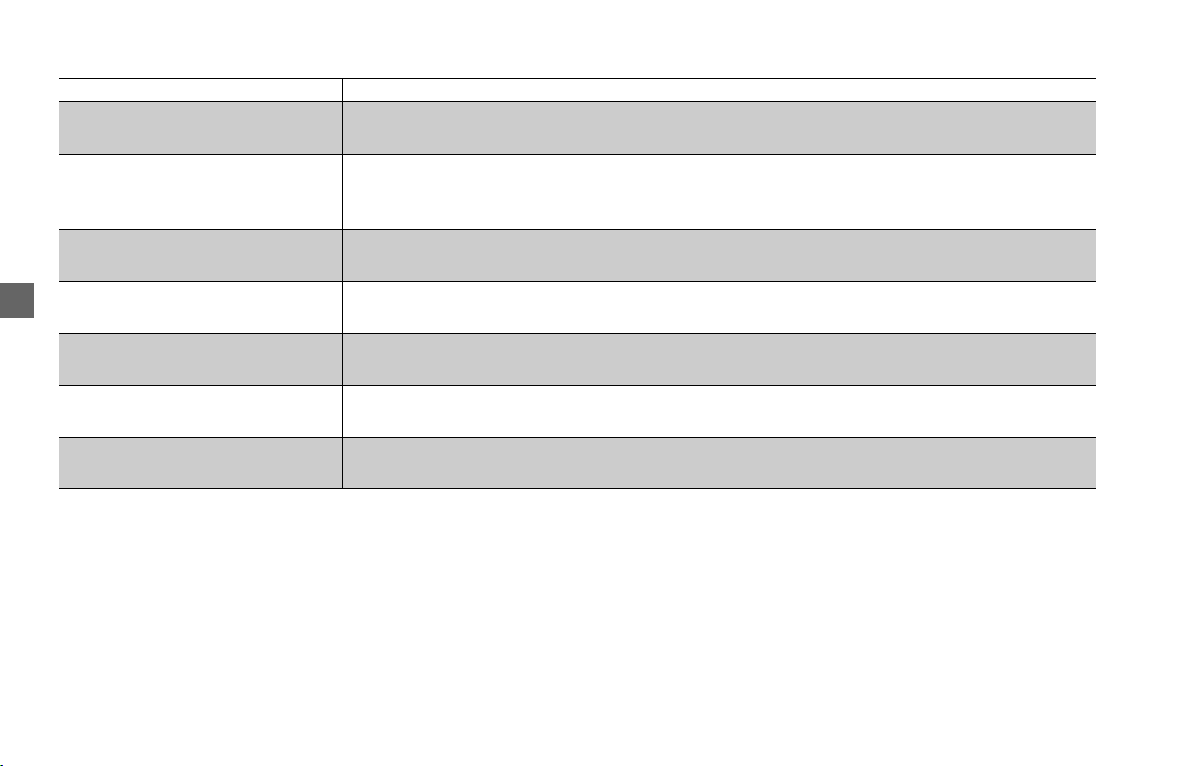
Audio System Trouble
206
Troubleshooting
If the problem continues after the above-described inspection, have your vehicle inspected by your dealer.
Symptom Cause/remedy
Audio system cannot operate.
Certain manual functions and settings are disabled or inoperable while the vehicle is in motion.
You cannot select a grayed-out menu until the vehicle is stopped.
Set menu in [Vehicle setting] does
not be reflected or inoperable.
In [Vehicle setting], certain items cannot be selected and display information is limited when the
ignition switch is in ACC. The set menu will be reflected to the previous setting when the ignition
switch is turned ON.
When turning the ignition switch
OFF and ON continuously.
Since the system restart takes time, it may take time until the screen is appeared.
High temperature/overcurrent
protection
To protect the system, some operations may be limited temporarily. The system automatically
recovers after the cause is solved.
About Idling Stop system
(GL1800D/DA Canada model)
When the Idling Stop system is activated, sound may not come out temporarily for system
protection, but sound will recover automatically.
Radio receiver sensitivity
The sensitivity of receiver is affected by the object which interrupts a radio wave nearby the radio
antenna (top of the right saddlebag).
Software update
The statements in this owner's manual may not match your vehicle's Audio System after
performing the software update (map data update).
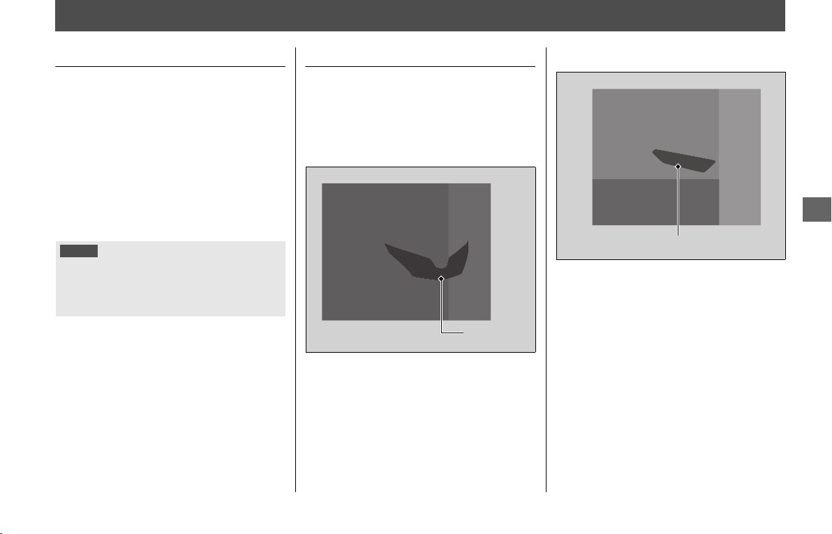
207
Troubleshooting
Electrical Trouble
Battery Goes Dead
Charge the battery using a motorcycle
battery charger.
Remove the battery from the vehicle before
charging.
Do not use an automobile-type battery
charger, as these can overheat a
motorcycle battery and cause permanent
damage.
If the battery does not recover after
recharging, contact your dealer.
Burned-out Light Bulb
All light bulbs on the vehicle are LEDs.
If there is an LED which is not turned on,
see your dealer for servicing.
❙
Headlight
The headlight uses several LEDs.
If there is an LED which is not turned on,
see your dealer for servicing.
❙
Front Turn Signal
The front turn signals use several LEDs.
If there is an LED which is not turned on,
see your dealer for servicing.
NOTICE
Jump starting using an automobile battery is not
recommended, as this can damage your vehicle’s
electrical system.
Bump starting is also not recommended.
Headlight
Front turn signal
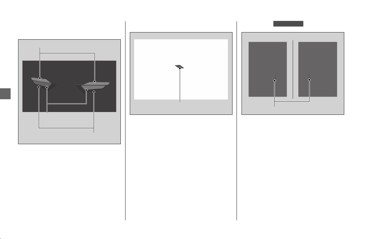
Electrical Trouble u Burned-out Light Bulb
208
Troubleshooting
❙
Brake light/Taillight/Rear Turn
Signal
The brake lights, taillights and rear turn
signals use several LEDs.
If there is an LED which is not turned on,
see your dealer for servicing.
❙
License Plate Light
The license plate light uses an LED.
If there is an LED which is not turned on,
see your dealer for servicing.
❙
Fog Light
The fog lights use several LEDs.
If there is an LED which is not turned on,
see your dealer for servicing.
Taillights
Brake lights
Rear turn signals
License plate light
GL1800/D/DA
Fog lights
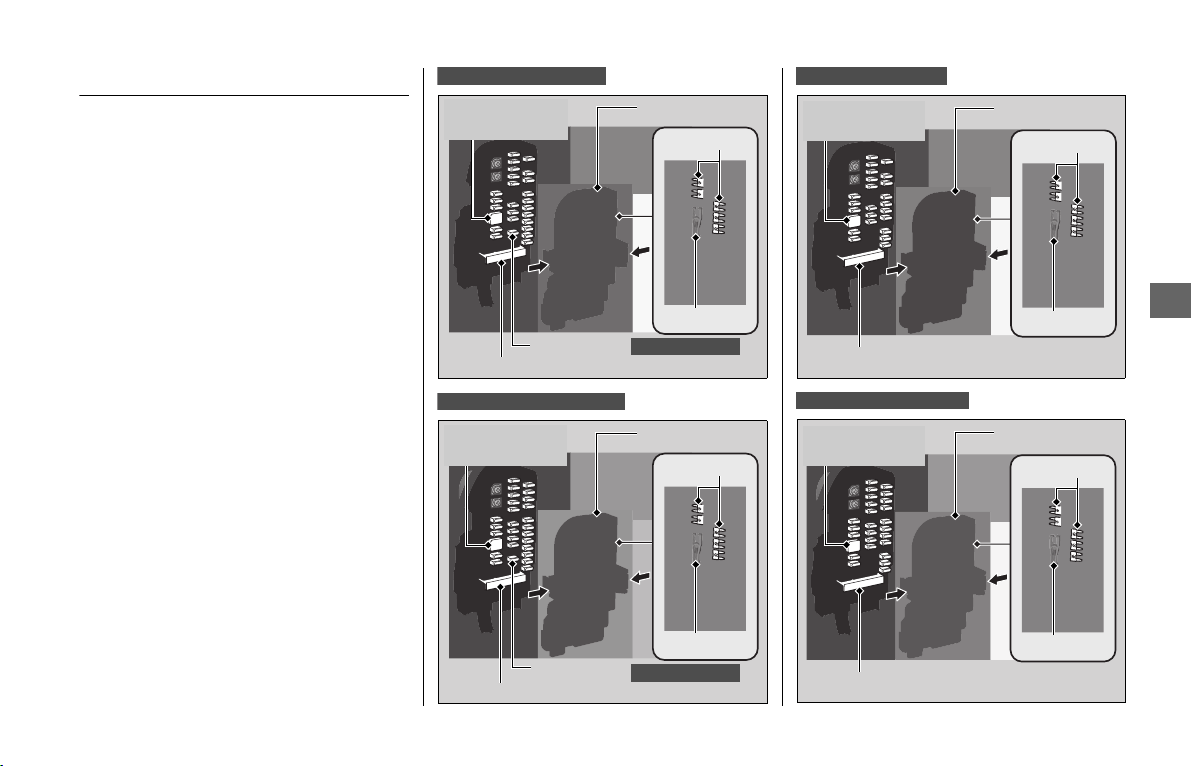
Electrical Trouble
u
Blown Fuse
209
Troubleshooting
Blown Fuse
Before handling fuses, see “Inspecting and
Replacing Fuses.”
2 P. 148
❙
Fuse Box Fuses
1.
Remove the left side cover. 2 P. 156
2.
Remove the fuse box cover.
3.
Pull the fuses out one by one with the
fuse puller and check for a blown fuse.
Always replace a blown fuse with a
spare fuse of the same rating.
u Spare fuses and fuse puller are provided
on back side of the fuse cover.
4.
Install the parts in the reverse order of
removal.
❙
Main Fuse B, Speed Limiter Fuse
and External Amplifier Fuse
To check and replace the main fuse B,
speed limiter fuse and external amplifier
fuse, see your dealer for servicing.
GL1800D/DA USA model
Spare fuses
Fuse puller
Main fuse B
Airbag fuse
GL1800DA only
Fuse box coverExternal
amplifier fuse
GL1800D/DA Canada model
Spare fuses
Fuse puller
Main fuse B
Airbag fuse
GL1800DA only
Fuse box coverExternal
amplifier fuse
GL1800BD USA model
Spare fuses
Fuse puller
Main fuse B
Fuse box cover
External
amplifier fuse
GL1800BD Canada model
Spare fuses
Fuse puller
Main fuse B
Fuse box cover
External
amplifier fuse
continued
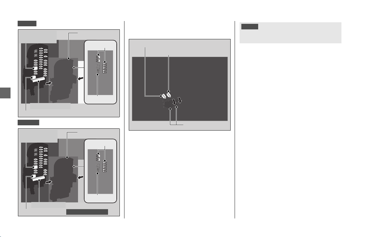
Electrical Trouble u Blown Fuse
210
Troubleshooting
❙
Ignition Main Fuse & ACC Main
Fuse
1.
Remove the left side cover. 2 P. 156
2.
Remove the fuse case covers.
3.
Pull the fuses out one by one with the
fuse puller and check for a blown fuse.
Always replace a blown fuse with a
spare fuse of the same rating.
u Spare fuses and fuse puller are provided
on back side of the fuse box cover.
4.
Install the parts in the reverse order of
removal.
GL1800
Spare fuses
Fuse puller
Main fuse B
Fuse box cover
External
amplifier fuse
Speed limiter fuse
GL1800B
Spare fuses
Fuse puller
Fuse box coverExternal
amplifier fuse
Main fuse B
Speed limiter fuse
Canada model only
Ignition main fuse
Fuse case covers
ACC main fuse
NOTICE
If a fuse fails repeatedly, you likely have an electrical
problem. Have your vehicle inspected by your dealer.

Information
Keys ....................................................... P. 212
Instruments, Controls, & Other Features
.... P. 214
Legal Information on Apple CarPlay ... P. 218
Caring for Your Vehicle........................ P. 220
Storing Your Vehicle ............................ P. 222
Transporting Your Vehicle ................... P. 223
You & the Environment ....................... P. 224
Vehicle Identification Number............. P. 225
Tire Pressure Monitoring System (TPMS)
Explanation ........................................... P. 226
Emission Control Systems .................... P. 227
Catalytic Converter............................... P. 230
Oxygenated Fuels .................................P. 231
Authorized Manuals .............................P. 232
Warranty Coverage and Service ..........P. 233
Honda Contacts.....................................P. 234
Customer Support.................................P. 235
Reporting Safety Defects ...........P. 236
USA
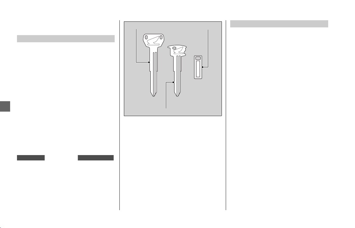
Keys
212
Information
Keys
This vehicle has emergency key, built-in key
and a key tag with a key number. Store the
emergency key and key tag in a safe
location.
Normally, the built-in key should be stored
in the Honda SMART Key.
2 P. 191
To make a duplicate key, take the key and
key tag to your dealer or a locksmith.
The emergency key and built-in key are
used to unlock the left saddle bag in an
emergency. 2 P. 191
Do not store the emergency key in the
saddlebags, fairing pocket, travel trunk
or shelter case .
Carrying the Honda SMART Key allows you
to perform the following operations:
● Locking or unlocking the steering and
activating or deactivating the electrical
system
● Releasing the left and right saddlebags
and travel trunk
● Releasing the fairing pocket
The ID number of the Honda SMART Key is
on the ID tag. You can also unlock the
steering (if it is locked) and activate the
electrical system by inputting the ID
number.
Always carry both the emergency key and
ID tag, but separate from the Honda
SMART Key, to avoid losing all of them at
the same time.
Also store a copy of your ID number in a
safe place other than your vehicle.
Emergency Key
GL1800/D/DA
Except GL1800DA
Emergency key
Built-in key
Key tag
Honda SMART Key
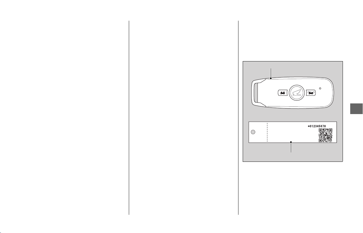
Keys
213
Information
The Honda SMART Key contains electronic
circuits. If the circuits are damaged, the
Honda SMART Key will not allow you to
perform any operations.
● Do not drop the Honda SMART Key or
set heavy objects on them.
● Protect the Honda SMART Key from
direct sunlight, high temperature, and
high humidity.
● Do not scratch or puncture.
● Do not store near any magnetized
products such as a magnetized key chain.
● Always keep the Honda SMART Key
away from electric appliances such as a
TV, radio, PC or low-frequency massage
device.
● Keep the Honda SMART Key away from
liquids. If it gets wet, dry it immediately
with a soft cloth.
● Keep the Honda SMART Key away from
the vehicle while washing the vehicle.
● Do not burn.
● Do not wash in an ultrasonic cleaner.
● If fuel, wax, or grease adhere to the
Honda SMART Key, wipe it off
immediately to avoid cracking or
warping.
● Do not disassemble the Honda SMART
Key other than when changing a battery.
Only the case of the Honda SMART Key
can be disassembled. Do not disassemble
other parts.
● Do not lose your Honda SMART Key. If
you lose it, you will need to register a
new Honda SMART Key. See your dealer
with your emergency key and ID tag for
registration.
The battery in the Honda SMART Key
system normally lasts about 2 years.
To get add additional Honda SMART Key,
take the Honda SMART Key and the vehicle
to your dealer.
Honda SMART Key
ID tag
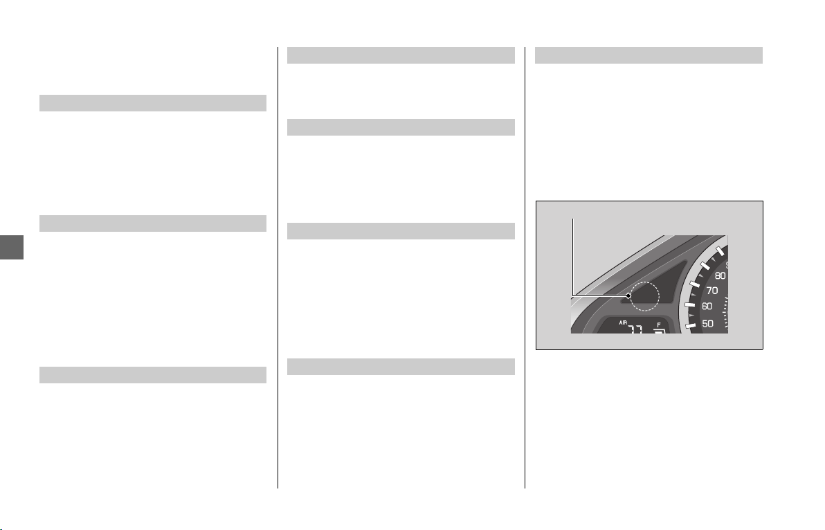
Instruments, Controls, & Other Features
214
Information
Instruments, Controls, &
Other Features
Leaving the ignition switch in ON or ACC
with the engine stopped will drain the
battery.
Do not turn the ignition switch while riding.
Do not use the engine stop switch except in
an emergency. Doing so when riding will
cause the engine to suddenly turn off,
making riding unsafe.
If you stop the engine using the engine
stop switch, turn the ignition switch OFF.
Failing to do so will drain the battery.
The display locks at 999,999 when the
read-out exceeds 999,999.
The tripmeters return to 0.0 when each
read-out exceeds 9,999.9.
The owner’s manual, Navigation System
manual, registration and insurance
information can be stored in the left
saddlebag.
A banking (lean angle) sensor automatically
stops the engine and fuel pump if the
vehicle falls over. To reset the sensor, you
must turn the ignition switch to OFF and
back to ON before the engine can be
restarted.
This model is equipped with a Throttle by
Wire System.
Do not put magnetized items or items
susceptible to magnetic interference near
the right handlebar switches.
The backlight brightness of the meter will
be controlled automatically when “AUTO”
is selected on the brightness setting.
Ambient brightness is detected by the
photosensor.
Do not damage or cover the photosensor.
Otherwise, the automatic brightness
control may not work properly.
Ignition Switch
Engine Stop Switch
Odometer
Tripmeter
Owner’s Manual
Ignition Cut-off System
Throttle by Wire System
Automatic Brightness Control
Photosensor

Instruments, Controls, & Other Features
215
Information
The audio systems on your vehicle emit
radio waves when in operation.
This device complies with Part 15 of the
FCC Rules. Operation is subject to the
following two conditions:
(1) this device may not cause harmful
interference, and
(2) this device must accept any interference
received, including interference that may
cause undesired operation.
FCC CAUTION:
Changes or modifications not expressly
approved by the party responsible for
compliance could void the user's authority
to operate the equipment.
This equipment complies with FCC’s RF
radiation exposure limits set forth for an
uncontrolled environment. The antenna(s)
used for this transmitter must be installed
and operated to provide a separation
distance of at least 20 cm from all persons
and must not be collocated or operating in
conjunction with any other antenna or
transmitter. Installers must ensure that
20 cm separation distance will be
maintained between the device (excluding
its handset) and users.
This Class B digital apparatus complies with
Canadian ICES-003.
This device complies with Industry Canada’s
licence-exempt RSSs. Operation is subject
to the following two conditions:
(1) This device may not cause interference,
and
(2) This device must accept any
interference, including interference that
may cause undesired operation of the
device.
This radio transmitter (12339A-MKCAU)
has been approved by Industry Canada to
operate with the antenna types with the
maximum permissible gain indicated in test
report.
Antenna types not included in the report,
having a gain greater than the maximum
gain indicated for that type, are strictly
prohibited for use with this device.
La operación de este equipo está sujeta a
las siguientes dos condiciones:
(1) es posible que este equipo o dispositivo
no cause interferencia perjudicial y
(2) este equipo o dispositivo debe aceptar
cualquier interferencia, incluyendo la que
pueda causar su operación no deseada.
Audio System
USA
Canada
Mexico
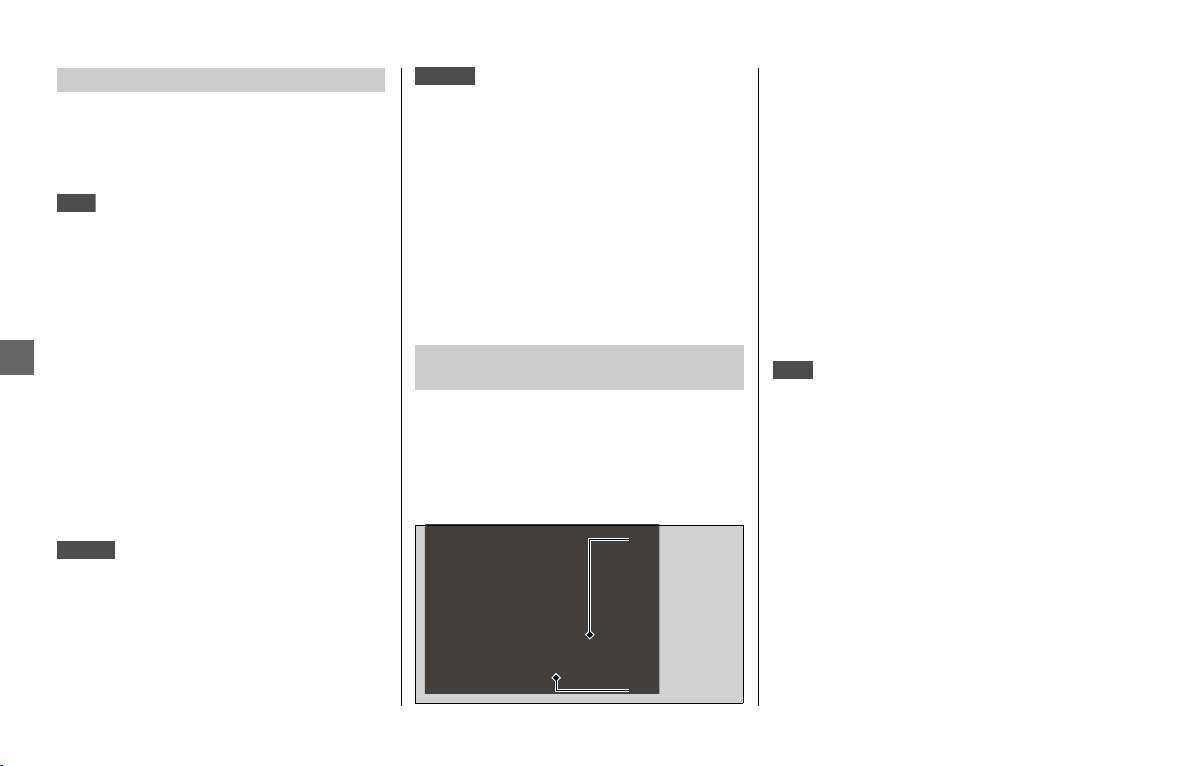
Instruments, Controls, & Other Features
216
Information
The Honda SMART Key system on your
vehicle emit radio waves when in
operation.
FCC CAUTION:
Changes or modifications not expressly
approved by the party responsible for
compliance could void the user’s authority
to operate the equipment.
This device complies with part 15 of the
FCC Rules. Operation is subject to the
following two conditions: (1) This device
may not cause harmful interference, and
(2) this device must accept any interference
received, including interference that may
cause undesired operation.
<GHR-H014-R>
IFETEL RLVOMGH17-1178
<GHR-H014-T>
IFETEL RLVOMGH17-1176
This device complies with Industry Canada’s
applicable licence-exempt RSSs.
Operation is subject to the following two
conditions:
(1) This device may not cause interference;
and
(2) This device must accept any
interference, including interference that
may cause undesired operation of the
device.
Your vehicle is equipped with a tire
pressure monitoring system (TPMS) that
turns on every time you start to ride the
vehicle and it monitors the pressure in your
tires while riding.
Each tire has its own pressure sensor. If the
air pressure of a tire becomes significantly
low while riding, the sensor in that tire
sends a signal that causes the low tire
pressure indicator to turn on.
Modifying the TPMS on your vehicle could
make the systems ineffective.
The Tire Pressure Monitoring System
(TPMS) on your vehicle emit radio waves
when in operation.
As required by the FCC:
This device complies with Part 15 of the
FCC rules. Operation is subject to the
following two conditions: (1) This device
may not cause harmful interference, and
(2) this device must accept any interference
received, including interference that may
cause undesired operation.
FCC CAUTION:
Changes or modifications not expressly
approved by the party responsible for
compliance could void the user’s authority
to operate the equipment.
Honda SMART Key System
USA
Mexico
Tire Pressure Monitoring System
(TPMS)
Canada
Tire pressure
sensor
Valve stem
USA

Instruments, Controls, & Other Features
217
Information
This device complies with Industry Canada
licence-exempt RSS standard(s). Operation
is subject to the following two conditions:
(1) this device may not cause interference,
and (2) this device must accept any
interference, including interference that
may cause undesired operation of the
device.
The assist-slipper clutch system helps to
prevent the rear tire from locking up when
the deceleration of your vehicle produces a
strong engine braking effect. It also makes
the clutch lever operation feel lighter.
Use only MA classification engine oil for
your vehicle. Using engine oil other than
MA classification oil could result in damage
to the assist-slipper clutch system.
❙
Event Data Recorders
Your vehicle is equipped with one or more
devices commonly referred to as event data
recorders.
These devices record airbag deployment
data, and the failure of any airbag system
component.
This data belongs to the vehicle owner and
may not be accessed by anyone else except
as legally required or with the permission of
the vehicle owner.
Canada
Assist-slipper Clutch System
GL1800/B
Airbag System
GL1800DA

Legal Information on Apple CarPlay
218
Information
Legal Information on
Apple CarPlay
USE OF APPLE CARPLAY IS SUBJECT TO
YOUR AGREEMENT TO THE CARPLAY
TERMS OF USE, WHICH ARE INCLUDED AS
PART OF THE APPLE iOS TERMS OF USE. IN
SUMMARY, THE CARPLAY TERMS OF USE
DISCLAIM APPLE AND ITS SERVICE
PROVIDERS’ LIABILITY IF THE SERVICES FAIL
TO PERFORM CORRECTLY OR ARE
DISCONTINUED, STRICTLY LIMIT APPLE
AND ITS SERVICE PROVIDERS’ OTHER
LIABILITIES, DESCRIBE THE KINDS OF USER
INFORMATION (INCLUDING, FOR
EXAMPLE, VEHICLE LOCATION, VEHICLE
SPEED, AND VEHICLE STATUS) BEING
GATHERED AND STORED BY APPLE AND
ITS SERVICE PROVIDERS, AND DISCLOSE
CERTAIN POSSIBLE RISKS ASSOCIATED
WITH THE USE OF CARPLAY, INCLUDING
THE POTENTIAL FOR DRIVER DISTRACTION.
SEE APPLE’S PRIVACY POLICY FOR DETAILS
REGARDING APPLE'S USE AND HANDLING
OF DATA UPLOADED BY CARPLAY.
YOU EXPRESSLY ACKNOWLEDGE AND
AGREE THAT USE OF APPLE CARPLAY
(“THE APPLICATIONS”) IS AT YOUR SOLE
RISK AND THAT THE ENTIRE RISK AS TO
SATISFACTORY QUALITY, PERFORMANCE,
ACCURACY AND EFFORT IS WITH YOU TO
THE MAXIMUM EXTENT PERMITTED BY
APPLICABLE LAW, AND THAT THE
APPLICATIONS AND INFORMATION ON
THE APPLICATIONS IS PROVIDED “AS IS”
AND “AS AVAILABLE,” WITH ALL FAULTS
AND WITHOUT WARRANTY OF ANY KIND,
AND HONDA HEREBY DISCLAIMS ALL
WARRANTIES AND CONDITIONS WITH
RESPECT TO THE APPLICATIONS AND
INFORMATION ON THE APPLICATIONS,
EITHER EXPRESS, IMPLIED OR STATUTORY,
INCLUDING, BUT NOT LIMITED TO, THE
IMPLIED WARRANTIES AND/OR
CONDITIONS OF MERCHANTABILITY,
SATISFACTORY QUALITY, FITNESS FOR A
PARTICULAR PURPOSE, ACCURACY,
QUIET ENJOYMENT, AND
NONINFRINGEMENT OF THIRD PARTY
RIGHTS. NO ORAL OR WRITTEN
INFORMATION OR ADVICE GIVEN BY
HONDA OR AN AUTHORIZED
REPRESENTATIVE SHALL CREATE A
WARRANTY. AS EXAMPLES, AND
WITHOUT LIMITATION, HONDA
DISCLAIMS ANY WARRANTY REGARDING
THE ACCURACY OF DATA PROVIDED BY
THE APPLICATIONS, SUCH AS THE
ACCURACY OF DIRECTIONS, ESTIMATED
TRAVEL TIME, SPEED LIMITS, ROAD
CONDITIONS, NEWS, WEATHER, TRAFFIC,
OR OTHER CONTENT PROVIDED BY APPLE,
THEIR AFFILIATES, OR THIRD PARTY
PROVIDERS; HONDA DOES NOT
GUARANTEE AGAINST LOSS OF
APPLICATION DATA, WHICH MAY BE LOST
AT ANY TIME; HONDA DOES NOT
GUARANTEE THAT THE APPLICATIONS OR
ANY SERVICES PROVIDED THROUGH
THEM WILL BE PROVIDED AT ALL TIMES OR
THAT ANY OR ALL SERVICES WILL BE
AVAILABLE AT ANY PARTICULAR TIME OR
LOCATION. FOR EXAMPLE, SERVICES MAY
BE SUSPENDED OR INTERRUPTED
WITHOUT NOTICE FOR REPAIR,
MAINTENANCE, SECURITY FIXES,
UPDATES, ETC., SERVICES MAY BE
OWNER’S MANUAL LICENSE/LIABILITY
STATEMENTS
DISCLAIMER OF WARRANTIES;
LIMITATION ON LIABILITY

Legal Information on Apple CarPlay
219
Information
UNAVAILABLE IN YOUR AREA OR
LOCATION, ETC. IN ADDITION, YOU
UNDERSTAND THAT CHANGES IN THIRD
PARTY TECHNOLOGY OR GOVERNMENT
REGULATION MAY RENDER THE SERVICES
AND/OR APPLICATIONS OBSOLETE AND/
OR UNUSABLE.
TO THE EXTENT NOT PROHIBITED BY LAW,
IN NO EVENT SHALL HONDA OR ITS
AFFILIATES BE LIABLE FOR PERSONAL
INJURY, OR ANY INCIDENTAL, SPECIAL,
INDIRECT OR CONSEQUENTIAL DAMAGES
WHATSOEVER, INCLUDING, WITHOUT
LIMITATION, DAMAGES FOR LOSS OF
PROFITS, CORRUPTION OR LOSS OF DATA,
FAILURE TO TRANSMIT OR RECEIVE ANY
DATA, BUSINESS INTERRUPTION OR ANY
OTHER COMMERCIAL DAMAGES OR
LOSSES, ARISING OUT OF OR RELATED TO
THE APPLICATIONS OR YOUR USE OF OR
INABILITY TO USE THE APPLICATIONS OR
INFORMATION ON THE APPLICATIONS,
HOWEVER CAUSED, REGARDLESS OF THE
THEORY OF LIABILITY (CONTRACT, TORT
OR OTHERWISE) AND EVEN IF HONDA
WERE ADVISED OF THE POSSIBILITY OF
SUCH DAMAGES. SOME STATES AND
JURISDICTIONS DISALLOW THE
EXCLUSION OR LIMITATION OF LIABILITY
FOR DAMAGES, SO THESE LIMITATIONS
AND EXCLUSIONS MAY NOT APPLY TO
YOU. IN NO EVENT SHALL HONDA’S
TOTAL LIABILITY TO YOU FOR ALL
DAMAGES (OTHER THAN AS MAY BE
REQUIRED BY APPLICABLE LAW IN CASES
INVOLVING PERSONAL INJURY) EXCEED
THE AMOUNT OF FIVE DOLLARS ($5.00).
THE FOREGOING LIMITATIONS WILL APPLY
EVEN IF THE ABOVE STATED REMEDY FAILS
OF ITS ESSENTIAL PURPOSE.

Caring for Your Vehicle
220
Information
Caring for Your Vehicle
Frequent cleaning and polishing is
important to ensure the life of your Honda.
A clean vehicle makes it easier to spot
potential problems.
In particular, seawater and salts used to
prevent ice on roads promote the
formation of corrosion. Always wash your
vehicle thoroughly after riding on coastal or
treated roads.
Allow the engine, muffler, brakes, and
other high-temperature parts to cool
before washing.
1.
Rinse your vehicle thoroughly using a low
pressure garden hose to remove loose
dirt.
2.
If necessary, use a sponge or a soft towel
with mild cleaner to remove road grime.
u
Clean the windscreen, headlight lens,
panels, and other plastic components
with extra care to avoid scratching
them. Avoid directing water into the air
cleaner, muffler, and electrical parts.
3.
Thoroughly rinse your vehicle with plenty
of clean water and dry with a soft, clean
cloth.
4.
After the vehicle dries, lubricate any
moving parts.
u Make sure that no lubricant spills onto
the brakes or tires. Brake discs, pads,
drum or shoes contaminated with oil
will suffer greatly reduced braking
effectiveness and can lead to a crash.
5.
Apply a coat of wax to prevent corrosion.
u Avoid products that contain harsh
detergents or chemical solvents. These
can damage the metal, paint, and
plastic on your vehicle.
Keep the wax clear of the tires and
brakes.
u If your vehicle has any matte painted
parts, do not apply a coat of wax to
the matte painted surface.
❙
Washing Precautions
Follow these guidelines when washing:
● Do not use high-pressure washers:
u High-pressure water cleaners can
damage moving parts and electrical
parts, rendering them inoperable.
u Water in the air intake can be drawn
into the throttle body and/or enter the
air cleaner.
● Do not direct water at the muffler:
u Water in the muffler can prevent
starting and causes rust in the muffler.
● Dry the brakes:
u Water adversely affects braking
effectiveness. After washing, apply the
brakes intermittently at low speed to
help dry them.
● Do not direct water in the left saddlebag:
u Water in the left saddlebag can
damage your documents and other
belongings.
● Do not direct water at the air cleaner:
u Water in the air cleaner can prevent
the engine from starting.
Washing

Caring for Your Vehicle
221
Information
● Do not direct water near the headlight.
u The headlight's inside lens may fog
temporarily after washing or while
riding in the rain. This does not impact
the headlight function.
However, if you see a large amount of
water or ice accumulated inside the
lens(es), have your vehicle inspected
by your dealer.
● Do not use wax or polishing compounds
on matte painted surface:
u Use a soft cloth or sponge, plenty of
water, and a mild detergent to clean
matte painted surfaces. Dry with a soft
clean cloth.
Aluminum will corrode from contact with
dirt, mud, or road salt. Clean aluminum parts
regularly and follow these guidelines to avoid
scratches:
● Do not use stiff brushes, steel wool, or
cleaners containing abrasives.
● Avoid riding over or scraping against
curbs.
Follow these guidelines to prevent
scratches and blemishes:
● Wash gently using a soft sponge and
plenty of water.
● To remove stubborn stains, use diluted
detergent and rinse thoroughly with
plenty of water.
● Avoid getting gasoline, brake fluid, or
detergents on the instruments, panels, or
headlight.
Keep the windscreen raised after turning
off the electrical system to make it easy to
clean.
2 P. 136
Using plenty of water, clean the
windscreen with a soft cloth or sponge.
(Avoid using detergents or any kind of
chemical cleaner on the windscreen.) Dry
with a soft, clean cloth.
For a dirtier windscreen, use a diluted
neutral detergent with a sponge and plenty
of water. Make sure to wash off all the
detergent. (Detergent residue may cause
windscreen cracks.)
Replace the windscreen if scratches cannot
be removed and they obstruct clear vision.
Take care to keep battery electrolyte, brake
fluid, or other chemical solvents off the
windscreen and screen garnish. They will
damage the plastic.
Aluminum Components
Panels
Windscreen
NOTICE
To avoid possible scratching or other damage, use only
water and a soft cloth or sponge to clean the
windscreen.

Storing Your Vehicle
222
Information
The instrument panel is coated with a
special surface treatment to prevent
reflection and glare.
Wipe any moisture (including rainwater) on
the instrument panel with a dry, soft cloth
immediately.
Using plenty of water, clean the instrument
panel with a soft cloth or sponge.
For a dirtier instrument panel, use a diluted
neutral detergent with a sponge and plenty
of water. Make sure to wash off all the
detergent. Dry with a soft, clean cloth.
Take care to keep battery electrolyte, brake
fluid, or other chemical solvents off the
instrument panel. They will damage the
special surface treatment of the instrument
panel.
The exhaust pipe and muffler are stainless
steel but may become stained by mud or
dust.
To remove mud or dust, use a wet sponge
and a liquid kitchen abrasive, then rinse
well with clean water. Dry with chamois or
a soft towel.
If necessary, remove heat stains by using a
commercially available fine texture
compound. Then rinse by the same manner
as removing mud or dust.
When the exhaust pipe and muffler are
painted, do not use a commercially
available abrasive kitchen cleaning
compound. Use a neutral detergent to
clean the painted surface on the exhaust
pipe and muffler. If you are not sure if your
exhaust pipe and muffler are painted,
contact your dealer.
Storing Your Vehicle
If you store your vehicle outdoors, you
should consider using a full-body cover.
If you won’t be riding for an extended
period, follow these guidelines:
● Wash your vehicle and wax all painted
surfaces (except matte painted surfaces).
Coat chrome pieces with rust-inhibiting
oil.
●
Place your vehicle on its center stand and
position a block so that both tires are off
the ground.
Place your vehicle on a maintenance stand
and position a block so that both tires are
off the ground.
● After rain, remove the body cover and
allow the vehicle to dry.
● Remove the battery (2 P. 153) to prevent
discharge. Charge the battery in a
shaded, well-ventilated area.
u If you leave the battery in place,
disconnect the negative
- terminal to
prevent discharge.
Instrument Panel Exhaust Pipe and Muffler
NOTICE
Even though the exhaust is made of stainless steel, it
can become stained. Remove all marks and blemishes
as soon as they are noticed.
GL1800/D/DA
GL1800B/BD
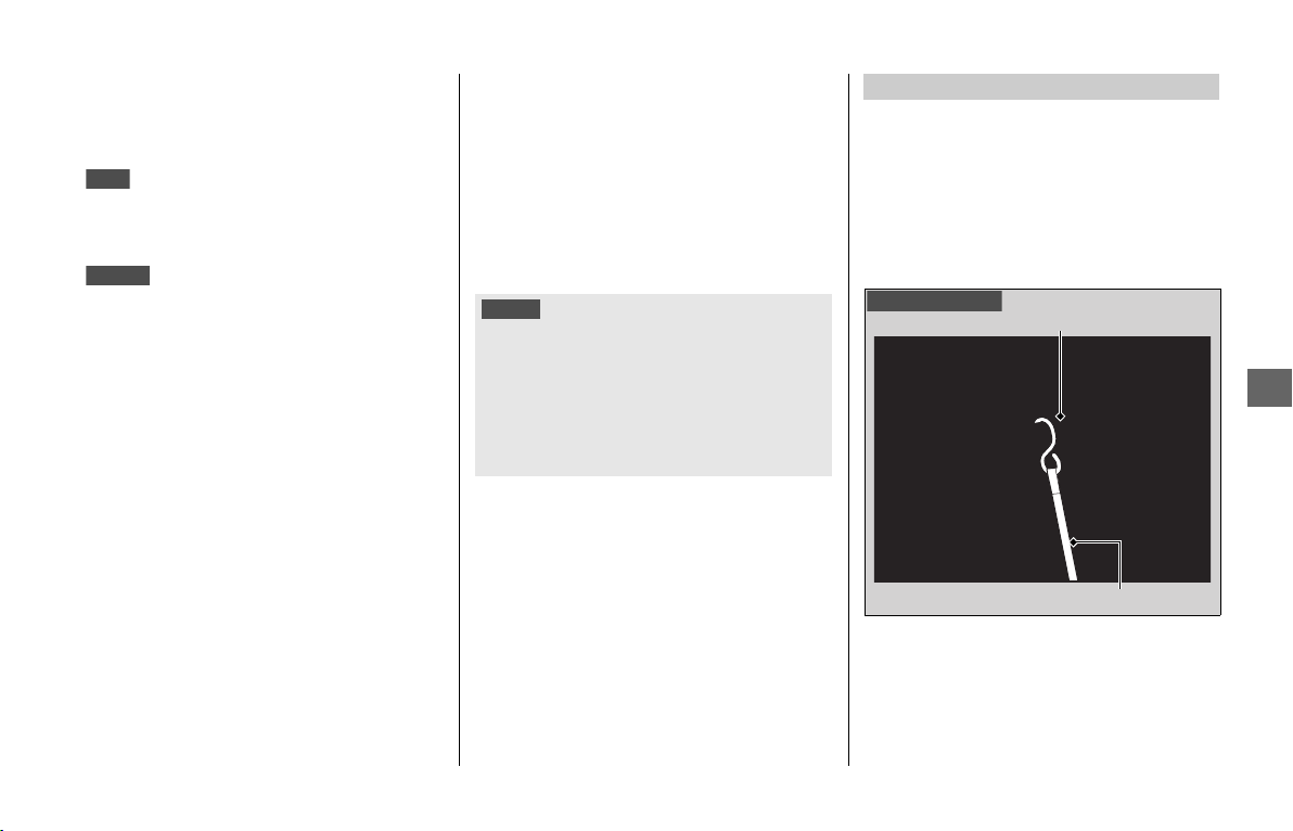
Transporting Your Vehicle
223
Information
After removing your vehicle from storage,
inspect all maintenance items required by
the Maintenance Schedule.
For more information about storage,
refer to the Honda Winter Storage Guide,
available from your dealer.
For more information about
storage, visit our website at www.honda.ca
and look up “Storage Tips” under the
“Honda Warranty” in the Warranty tab for
your Model.
Transporting Your Vehicle
If your vehicle needs to be transported, it
should be carried on a motorcycle trailer or
a flatbed truck or trailer that has a loading
ramp or lifting platform, and motorcycle
tie-down straps. Never try to tow your
vehicle with a wheel or wheels on the
ground.
1.
Remove both sides of the cylinder head
side covers. 2 P. 154
2.
Secure the vehicle using a buckle or ratchet
style tie-down strap to the engine guards
and affix the other ends to an anchor point.
u Make sure the tie-downs straps are tight
and the vehicle is secure.
USA
Canada
NOTICE
• Towing your vehicle can cause serious damage to
the transmission.
• When tying down the vehicle for transportation,
do not use tie-downs or straps on the handlebars
or handgrips. Doing so may cause damage to the
steering system, heated grips and/or handlebar
switches.
Tie-down Method
Engine guard
Left side shown
Tie-down strap
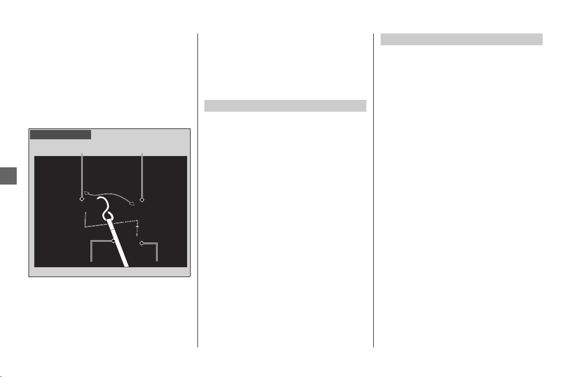
You & the Environment
224
Information
3.
Remove both left and right saddlebag
guard covers by removing the clips to
expose the saddlebag guards.
4.
Secure the vehicle using a buckle or ratchet
style tie-down strap to the saddlebag
guards and affix the other ends to an
anchor point.
u Make sure the tie-downs straps are tight
and the vehicle is secure.
You & the Environment
Owning and riding a vehicle can be
enjoyable, but you must do your part to
protect the environment.
Use a biodegradable detergent when you
wash your vehicle. Avoid aerosol spray
cleaners that contain chlorofluorocarbons
(CFCs) which damage the atmosphere’s
protective ozone layer.
Put oil and other toxic wastes in approved
containers and take them to a recycling
center.
Call your local or state office of public
works or environmental services to find a
recycling center in your area, and to get
instructions on how to dispose of non-
recyclable wastes. Do not place used
engine oil in the trash, or pour it down a
drain or on the ground. Used oil, gasoline,
coolant, and cleaning solvents contain
poisons that can hurt refuse workers and
contaminate drinking water, lakes, rivers,
and oceans.
Left side shown
Clip
Muffler guard
Muffler guard
cover
Tie-down strap
Choose Sensible Cleaners
Recycle Wastes
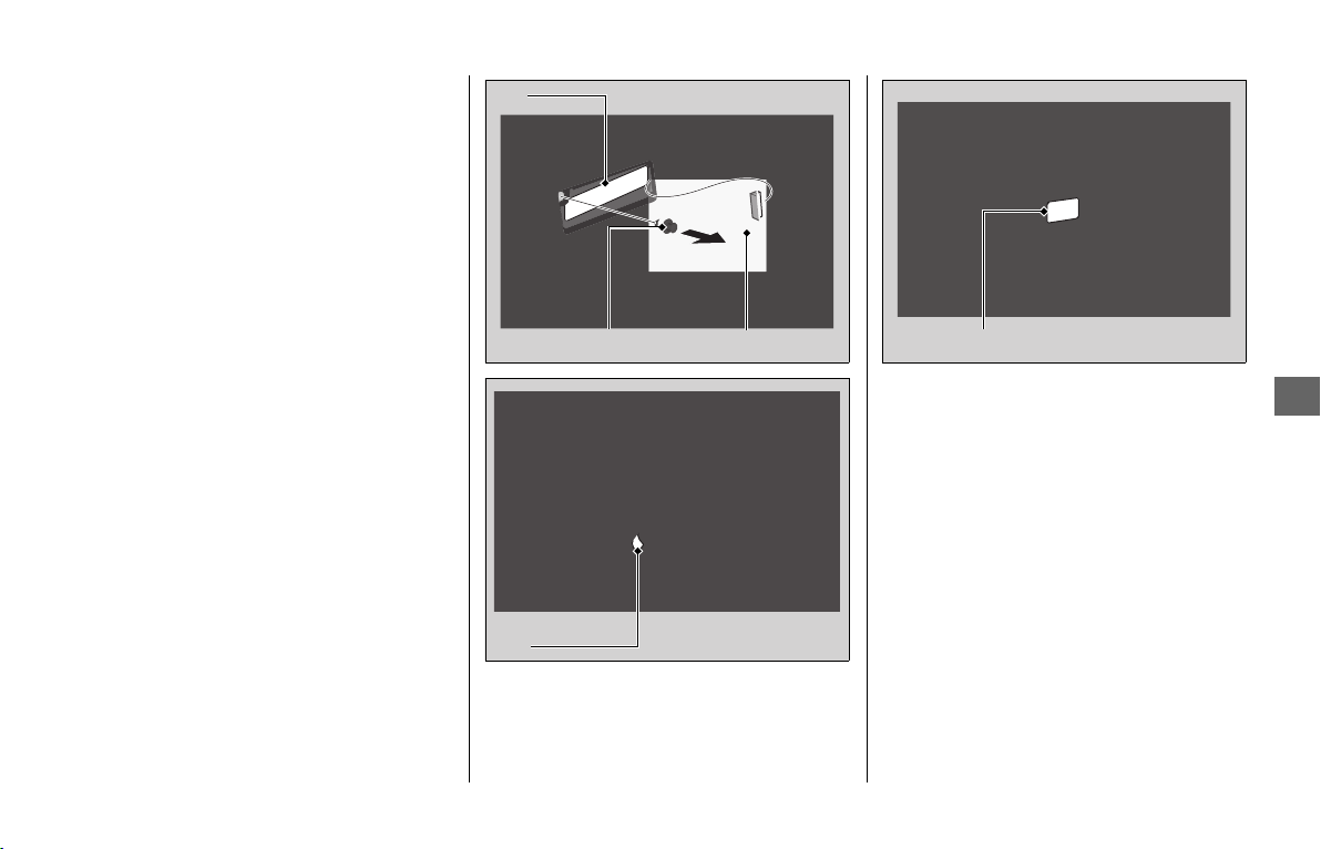
Vehicle Identification Number
225
Information
Vehicle Identification
Number
The VIN and engine serial number uniquely
identify your vehicle and are required in
order to register your vehicle. They may
also be required when ordering
replacement parts.
To check the VIN, remove the cover by
releasing the clip.
You should record these numbers and keep
them in a safe place.
VIN
Clip
Cover
VIN
Engine number
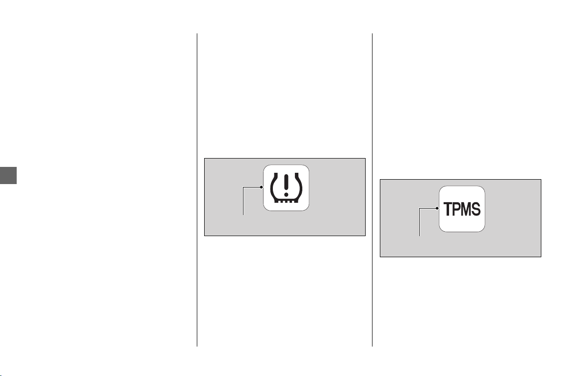
Tire Pressure Monitoring System (TPMS) Explanation
226
Information
Tire Pressure Monitoring
System (TPMS) Explanation
Both tires should be checked monthly
when cold, and inflated to the inflation
pressure recommended by the vehicle
manufacturer on the tire information label.
(If your vehicle has different tires than those
indicated on the vehicle tire information
label, you should determine the proper tire
inflation pressure for those tires.)
As an added safety feature, your vehicle
has been equipped with a tire pressure
monitoring system (TPMS) that illuminates
a low tire pressure indicator when one or
more of your tires significantly under-
inflated.
Accordingly, when the low tire pressure
indicator illuminates, you should stop and
check your tires as soon as possible, and
inflate them to the proper pressure.
Riding on a significantly under-inflated tire
causes the tire to overheat and can lead to
tire failure. Under-inflation also reduces
fuel efficiency and tire tread life, and may
affect the vehicle’s handling and stopping
ability.
Please note that the TPMS is not a
substitute for proper tire maintenance, and
it is the rider’s responsibility to maintain
correct tire pressure, even if under-inflation
has not reached the level to trigger
illumination of the low tire pressure
indicator.
Your vehicle has also been equipped with a
TPMS indicator to indicate when the system
is not operating properly. The TPMS
indicator displays the symbol “TPMS”
when illuminated.
When the TPMS indicator is illuminated,
the system may not be able to detect or
signal low tire pressure as intended.
TPMS malfunctions may occur for a variety
of reasons, including the installation of
replacement or alternate tires or wheels on
the vehicle that prevent the TPMS from
functioning properly.
Always check the TPMS indicator after
replacing one or more tires or wheels on
your vehicle to ensure that the replacement
or alternate tires and wheels allow the
TPMS to continue to function properly.
Low tire pressure indicator
TPMS indicator
Emission Control Systems
227
Information
Emission Control Systems
Your vehicle engine emits combustion by-
products, including carbon monoxide (CO),
oxides of nitrogen (NOx), and hydrocarbons
(HC). Gasoline evaporation also emits
hydrocarbons. Controlling the production
of NOx, CO, and HC is important for the
environment.
The U.S. Environmental Protection Agency
(EPA), the California Air Resources Board
(CARB), and Environment and Climate
Change Canada (ECCC) require that your
vehicle comply with applicable exhaust,
crankcase, and fuel permeation emission
standards during its useful life, when
operated and maintained according to the
instructions provided.
CARB also requires that your vehicle
comply with applicable evaporative
emission requirements during its useful life,
when operated and maintained according
to the instructions provided.
Compliance with the terms of the
Distributor’s Warranties for Honda
Motorcycle Emission Control Systems is
necessary in order to maintain a valid
emissions system warranty.
The Vehicle Emission Control Information
label is attached inside the left saddlebag.
Exhaust Emission Requirements
USA
Vehicle emission control
information label
Canada
Vehicle emission control
information label

Emission Control Systems
228
Information
The EPA requires that vehicles built after
January 1, 1983 comply with applicable
noise emission standards for one year or
3,730 miles (6,000 km) after the time of
purchase when operated and maintained
according to the instructions provided.
The exhaust emission control system
includes the following components that
should not need adjustment, although
periodic inspection by your dealer is
recommended.
❙
PGM-FI System
The PGM-FI (programmed fuel injection)
system uses sequential multiport fuel
injection, and is comprised of air intake,
engine control, fuel control, and exhaust
control subsystems.
The engine control module (ECM) uses
sensors to determine how much air enters
the engine, and then controls how much
fuel to inject.
❙
Ignition Timing Control System
The ignition timing control system adjusts
the ignition timing to reduce the amount of
HC, CO, and NOx produced.
❙
Secondary Air Injection System
The secondary air injection system adds
filtered air into the exhaust gas to help
improve emission control performance.
❙
Catalytic Converters
The exhaust system contains one or more
catalytic converters. Catalytic converters
use a catalyst to convert most of the
harmful exhaust gas compounds into
harmless compounds.
Noise Emission Requirements Exhaust Emission Control System

Emission Control Systems
229
Information
An evaporative emissions control system
uses a canister filled with charcoal to
adsorb fuel vapor from the fuel tank while
the engine is off. The vapor is drawn into
the engine and burned while riding.
The engine is equipped with a closed
crankcase system to prevent discharging
crankcase emissions into the atmosphere.
Blow-by gas is returned to the combustion
chamber through the air cleaner housing
and throttle body.
The fuel tank, fuel hoses, and fuel vapor
charge hoses use fuel permeation control
technologies to prevent fuel vapor
emissions.
Tampering with these components to
reduce or defeat the effectiveness of the
fuel permeation technologies is prohibited.
❙
TAMPERING WITH THE NOISE CONTROL
SYSTEM IS PROHIBITED:
U. S. federal law prohibits, and Canadian
provincial laws may prohibit, the following
acts or the causing thereof: (1) The removal
or rendering inoperative by any person,
other than for purposes of maintenance,
repair or replacement, of any device or
element of design incorporated into any
new vehicle for the purpose of noise
control prior to its sale or delivery to the
ultimate purchaser or while it is in use; or
(2) the use of the vehicle after such device
or element of design has been removed or
rendered inoperative by any person.
❙
AMONG THOSE ACTS PRESUMED TO
CONSTITUTE TAMPERING ARE THE
FOLLOWING ACTS:
● Removal of, or puncturing the muffler,
baffles, header pipes or any other
component which conducts exhaust
gases.
● Removal of, or puncturing of any part of
the intake system.
● Lack of proper maintenance.
● Removing or disabling any emissions
compliance component, or replacing any
compliance component with a non-
compliant component.
Have your vehicle inspected and repaired
by your dealer if you experience any of the
following symptoms:
● Hard starting or stalling after starting
● Rough idling
● Misfiring or backfiring during
acceleration
● Poor engine performance and poor fuel
economy
Evaporative Emission Control System
Crankcase Emissions Control System
Fuel Permeation Emission Control
50 STATE (meets California)
Noise Emission Control System
Problems Affecting Vehicle Exhaust
Emissions

Catalytic Converter
230
Information
Catalytic Converter
This vehicle is equipped with two three-way
catalytic converters. Each catalytic
converter contains precious metals that
serve as catalysts in high temperature
chemical reactions that convert
hydrocarbons (HC), carbon monoxide (CO),
and oxides of nitrogen (NOx) in the exhaust
gasses into safe compounds.
A defective catalytic converter contributes
to air pollution and can impair your
engine’s performance. A replacement unit
must be an original Honda part or
equivalent.
Follow these guidelines to protect your
vehicle’s catalytic converters.
● Always use unleaded gasoline. Leaded
gasoline will damage the catalytic
converters.
● Keep the engine in good running
condition.
A poorly running engine can cause the
catalytic converter to overheat causing
damage to the converter or the vehicle.
● If your engine is misfiring, backfiring,
stalling, or otherwise not running
properly, stop riding and turn off the
engine. Have your vehicle serviced as
soon as possible.

Oxygenated Fuels
231
Information
Oxygenated Fuels
Some conventional fuels blended with
alcohol or an ether compound are available
in some locales to help reduce emissions to
meet clean air standards.
These gasolines are collectively referred to
as oxygenated fuels. If you plan to use
oxygenated fuel, check that it is unleaded
and meets the minimum octane rating and
blend requirement.
The following fuel blends are EPA-
approved and have been approved for use
in your vehicle:
● Ethanol (ethyl alcohol) up to 10% by
volume.
u Gasoline containing ethanol may be
marketed under the name Gasohol.
● Methanol (methyl alcohol) up to 5% by
volume that contain cosolvents and
corrosion inhibitors to protect the fuel
system. Never use a blend containing
more than 5%.
If you accidentally fill your fuel tank with an
oxygenated fuel containing higher
percentages, you may experience
performance problems. To resolve the
problem, have your dealer drain the fuel
tank and replace with the correct fuel. Fuel
system or performance problems resulting
from the use of an oxygenated fuel
containing higher percentages are not
covered by your warranty.
If you notice any undesirable operating
symptoms or performance problems, try a
different brand of gasoline.
NOTICE
Improper use of oxygenated fuels can damage metal,
rubber, and plastic parts of your fuel system.
Oxygenated fuel can also damage paint. Damage
caused by spilled fuel is not covered by warranty.
Authorized Manuals
232
Information
Authorized Manuals
The Service Manual used by your
authorized dealer is available from your
Honda dealer or Helm, Inc.
See your dealer to order
authorized manuals.
Also available, but not necessary to service
your model, is the Honda Common Service
Manual, which explains basic service
information for various systems on Honda
motorcycles, scooters, and ATV.
The Winter Storage Guide in
conjunction with the Owner's Manual and
Service Manual can help you prepare your
Honda motorcycle, scooter, ATV, and SxS
for winter storage.
These Honda manuals are written for the
professional technician. However, if you
possess the proper tools, observe the safety
standards, and are mechanically capable,
you should find them easy to use.
Special Honda tools are necessary for some
procedures.
USA
Canada
USA
Order online: www.helminc.com
Order Toll Free: 1-888-CYCLE93
(1-888-292-5393)
(NOTE: For Credit Card Orders Only)
Monday - Friday 8:00 AM - 6:00 PM EST
Publication Item No. Description
61MKC02 2020 GL1800/B/BD/D/DA Service Manual
61CSM00 Common Service Manual
S9507 Winter Storage Guide
31MKC620 2020 GL1800/B/BD/D/DA Owner’s Manual
31MKCT20 2020 GL1800/B/BD/D/DA Navigation
System Manual
USA
USA

Warranty Coverage and Service
233
Information
Warranty Coverage and
Service
Your new Honda is covered by the
following warranties:
● Vehicle Limited Warranty
● Emission Control System Warranty
● Noise Control Warranty
The responsibilities, restrictions, and
exclusions that apply to these warranties
are explained in the Warranties Booklet
given to you by your Honda dealer at the
time of purchase. Always keep your Honda
owner’s card with your Warranties Booklet.
Please refer to the Warranty
Booklet posted on our website at
www.honda.ca.
It is important to realize that your warranty
applies only to defects in material or
workmanship of your Honda.
Your warranty coverage does not apply to
the normal wear and deterioration
associated with use of the vehicle.
Your warranty coverage is not voided if you
perform your own maintenance.
However, failures that occur due directly to
improper maintenance are not covered by
these warranties.
You can extend almost all of your
warranty coverage through the Honda
Protection Plan. For more information, see
your Honda dealer.
Please remember that maintenance
recommended in the Maintenance
Schedule is not included in your warranty
coverage.
If you believe you have a problem with your
vehicle, call the service department of your
Honda dealer. Make an appointment for an
inspection and diagnosis. You will be asked
to authorize that inspection, and your
dealer will return the results of the
inspection. If a problem exists and is
covered under warranty, your dealer will
perform the warranty repairs.
If you have any questions about your
warranty coverage or the nature of the
repair, talk to the Service Manager of your
Honda dealer.
If a misunderstanding occurs and you aren’t
satisfied with your dealer’s handling of the
situation, we suggest you discuss your
problem with the appropriate member of the
dealership’s management team. If you are still
not satisfied, contact the owner of the
dealership or their designated representative.
Coverage
USA
Canada
USA
Service

Honda Contacts
234
Information
Honda Contacts
If you wish to contact Honda directly to
comment on your experiences with your
vehicle or with your dealer, please send
your comments to the following address:
Motorcycle Division,
American Honda Motor Co., Inc.,
P.O. Box 2200, Torrance,
CA 90509-2200
Mailstop: 100-4C-7B,
Telephone: (866) 784-1870.
Honda Canada Inc.
Customer Relations Department,
180 Honda Boulevard
Markham, Ontario
L6C 0H9
Telephone: (888) 946-6329
Fax: (877) 939-0909
E-mail: [email protected]m
Please include the following information in
your letter:
● Name, address, and telephone number
● Product model, year, and VIN
● Date of purchase
● Dealer name and address
We will likely ask your Honda dealer to
respond, or possibly acknowledge your
comments directly.
The service department of your Honda
dealer offers trained personnel to perform
regular maintenance and most repairs. It
has the latest available service information
from Honda and also handles warranty
inspections and repairs.
The parts department offers Honda
Genuine Parts, Pro Honda products, Honda
Genuine Accessories (USA only), and
Honda accessories and products (Canada
only) that provide the same quality that
went into your vehicle.
The sales department offers the
Honda Protection Plan to extend almost all
of your warranty coverage.
Your Honda dealer can also supply
information about, riding events, and
information about safety training available
in your local area.
American Honda Motor Co., Inc.
Canada
Your Honda Dealer
USA

Customer Support
235
Information
Customer Support
You may contact Honda Customer Service,
Motorcycle Division, American Honda
Motor Co., Inc., P.O. Box 2200, mailstop:
100-4C-7B, Torrance, CA 90509-2200.
Telephone: (866) 784-1870.
Honda is continually expanding the scope
of the Map software and the Audio/
Navigation System software. The softwares
are updated to correspond with new
version releases.
For the software updates, visit our website
www.powersports.honda.com.
For the software updates, contact your
dealer.
Honda Customer Support
Audio/Navigation System Software
and Map Software Upgrades
USA
Canada

Reporting Safety Defects
236
Information
Reporting Safety
Defects
If you believe that your vehicle has a
defect which could cause a crash or
could cause injury or death, you
should immediately inform the
National Highway Traffic Safety
Administration (NHTSA) in addition
to notifying American Honda Motor
Co., Inc.
If NHTSA receives similar complaints,
it may open an investigation, and if it
finds that a safety defect exists in a
group of vehicles, it may order a
recall and remedy campaign.
However, NHTSA cannot become
involved in individual problems
between you, your dealer, or
American Honda Motor Co., Inc.
To contact NHTSA, you may call the
Vehicle Safety Hotline toll-free at:
1-888-327-4236
(TTY: 1-800-424-9153); go to
http://www.safercar.gov;
or write to:
Administrator, NHTSA,
1200 New Jersey Avenue, SE.,
Washington, DC 20590.
You can also obtain other
information about motor vehicle
safety from:
http://www.safercar.gov.
USA
237
Specifications
■ Main Components
*1 Including rider, all luggage, and accessories
■ Service Data
Overall length
GL1800BD
97.4 in (2,475 mm)
GL1800D/DA
101.4 in (2,575 mm)
Overall width 35.6 in (905 mm)
Overall height
GL1800BD
52.8 in (1,340 mm)
GL1800D/DA
56.3 in (1,430 mm)
Wheelbase 66.7 in (1,695 mm)
Minimum ground
clearance
5.1 in (130 mm)
Caster angle 30.5º
Trail 4.3 in (109 mm)
Curb weight
GL1800BD
USA model
800 lb (363 kg)
GL1800BD
Canada model
802 lb (364 kg)
GL1800D
USA model
836 lb (379 kg)
GL1800D
Canada model
838 lb (380 kg)
GL1800DA
USA model
844 lb (383 kg)
GL1800DA
Canada model
847 lb (384 kg)
Maximum weight
capacity*
1
GL1800BD
421 lb (191 kg)
GL1800D
423 lb (192 kg)
GL1800DA
417 lb (189 kg)
GL1800BD/D/DA
Maximum luggage
weight
Travel trunk
(Except GL1800BD)
20.0 lb (9.0 kg)
Each saddlebag 20.0 lb (9.0 kg)
Fairing pocket 4.5 lb (2.0 kg)
Shelter case
(Except GL1800DA)
6.6 lb (3.0 kg)
Passenger capacity Rider and 1 passenger
Minimum turning
radius
11.2 ft (3.4 m)
Displacement 111.8 cu-in (1,833 cm
3
)
Bore x stroke 2.87 x 2.87 in (73.0 x 73.0 mm)
Compression ratio 10.5:1
Fuel
Unleaded gasoline
Recommended: 86 PON or higher
Tank capacity 5.5 US gal (21 liters)
Battery
GYZ20L
12 V-20 Ah (10 HR)
Gear ratio
1st 2.166
2nd 1.695
3rd 1.304
4th 1.038
5th 0.820
6th 0.666
7th 0.521
Reverse 4.373
Reduction ratio
(primary /
secondary / final)
1.795 / 0.972 / 2.615
Tire size
Front 130/70R18M/C 63H
Rear 200/55R16M/C 77H
Tire type Radial, tubeless
Recommended
Tire
Front
BRIDGESTONE G853 RADIAL G
DUNLOP D423F
Rear
BRIDGESTONE G852 RADIAL G
DUNLOP D423
Tire air pressure
Front 36 psi (250 kPa, 2.50 kgf/cm
2
)
Rear 41 psi (280 kPa, 2.80 kgf/cm
2
)
Minimum tread
depth
Front 0.06 in (1.5 mm)
Rear 0.08 in (2.0 mm)
Spark plug (standard) CR6HSB-9 (NGK)
Spark plug gap
0.031 to 0.035 in (0.80 to
0.90 mm)
Idle speed
(non-
adjustable)
730 ± 100 rpm
Recommended
engine oil
API Service Classification SG or higher
except oils labeled as energy conserving or
resource conserving on the circular API
service label, SAE 10W-30, JASO T 903
standard MA, Pro Honda GN4 4-stroke oil
(USA & Canada) or Honda 4-stroke oil, or an
equivalent motorcycle oil
Engine oil
capacity
After draining 4.6 US qt (4.4 liters)
After draining &
engine oil filter
change
4.9 US qt (4.6 liters)
After draining,
engine & clutch oil
filter change
4.9 US qt (4.6 liters)
After disassembly 5.9 US qt (5.6 liters)
Specifications
continued

Specifications
238
Specifications
■ Bulbs
■ Fuses
■ Torque Specifications
Recommended
final drive oil
Hypoid gear oil SAE 80
Final drive oil
capacity
After draining 4.7 US oz (140 cm
3
)
After disassembly 5.4 US oz (160 cm
3
)
Recommended
brake fluid
Honda DOT 4 Brake Fluid
Cooling system
capacity
3.06 US qt (2.90 liters)
Recommended
coolant
Pro Honda HP Coolant
Headlight LED
Brake light LED
Taillight LED
Front turn signal light LED
Rear turn signal light LED
License plate light LED
Fog light (GL1800D/DA) LED
Ignition main fuse 30 A
ACC main fuse 20 A
Main fuse B 120 A
External amplifier fuse 40 A
Other fuse 30 A, 15 A, 10 A, 5 A
Oil filter 19 lbf·ft (26 N·m, 2.7 kgf·m)
Engine oil drain bolt A 22 lbf·ft (30 N·m, 3.1 kgf·m)
Engine oil drain bolt B 22 lbf·ft (30 N·m, 3.1 kgf·m)
Engine oil drain bolt C 22 lbf·ft (30 N·m, 3.1 kgf·m)
Final drive oil fill hole
cap
5.9 lbf·ft (8 N·m, 0.8 kgf·m)
Final drive oil drain bolt 9 lbf·ft (12 N·m, 1.2 kgf·m)
Front wheel axle bolt 44 lbf·ft (59 N·m, 6.0 kgf·m)
Front wheel axle pinch
bolt
16 lbf·ft (22 N·m, 2.2 kgf·m)
Front wheel brake
caliper mounting bolt
31 lbf·ft (42.5 N·m, 4.3 kgf·m)
Rear wheel nut 80 lbf·ft (108 N·m, 11.0 kgf·m)
Specifications
239
Specifications
■ Main Components
*1 Including rider, all luggage, and accessories
■ Service Data
Overall length
GL1800
101.4 in (2,575 mm)
GL1800B
97.4 in (2,475 mm)
Overall width 36.4 in (925 mm)
Overall height
GL1800
56.3 in (1,430 mm)
GL1800B
52.8 in (1,340 mm)
Wheelbase 66.7 in (1,695 mm)
Minimum ground
clearance
5.1 in (130 mm)
Caster angle 30.5º
Trail 4.3 in (109 mm)
Curb weight
GL1800
USA model
836 lb (379 kg)
GL1800
Canada model
838 lb (380 kg)
GL1800B
USA model
787 lb (357 kg)
GL1800B
Canada model
805 lb (365 kg)
Maximum weight
capacity*
1
GL1800
423 lb (192 kg)
GL1800B
421 lb (191kg)
Maximum luggage
weight
Travel trunk
(Except GL1800B)
20.0 lb (9.0 kg)
Each saddlebag 20.0 lb (9.0 kg)
Fairing pocket 4.5 lb (2.0 kg)
Shelter case 6.6 lb (3.0 kg)
Passenger capacity Rider and 1 passenger
Minimum turning
radius
11.2 ft (3.4 m)
GL1800/B
Displacement 111.8 cu-in (1,833 cm
3
)
Bore x stroke 2.87 x 2.87 in (73.0 x 73.0 mm)
Compression ratio 10.5:1
Fuel
Unleaded gasoline
Recommended: 86 PON or higher
Tank capacity 5.5 US gal (21 liters)
Battery
GYZ20L
12 V-20 Ah (10 HR)
Gear ratio
1st 2.200
2nd 1.416
3rd 1.035
4th 0.820
5th 0.666
6th 0.521
Reduction ratio
(primary /
secondary / final)
1.795 / 0.972 / 2.615
Tire size
Front 130/70R18M/C 63H
Rear 200/55R16M/C 77H
Tire type Radial, tubeless
Recommended
Tire
Front
BRIDGESTONE G853 RADIAL G
DUNLOP D423F
Rear
BRIDGESTONE G852 RADIAL G
DUNLOP D423
Tire air pressure
Front 36 psi (250 kPa, 2.50 kgf/cm
2
)
Rear 41 psi (280 kPa, 2.80 kgf/cm
2
)
Minimum tread
depth
Front 0.06 in (1.5 mm)
Rear 0.08 in (2.0 mm)
Spark plug (standard) CR6HSB-9 (NGK)
Spark plug gap
0.031 to 0.035 in (0.80 to
0.90 mm)
Idle speed
(non-
adjustable)
730 ± 100 rpm
Recommended
engine oil
API Service Classification SG or higher
except oils labeled as energy conserving or
resource conserving on the circular API
service label, SAE 10W-30, JASO T 903
standard MA, Pro Honda GN4 4-stroke oil
(USA & Canada) or Honda 4-stroke oil, or an
equivalent motorcycle oil
Engine oil
capacity
After draining 3.7 US qt (3.5 liters)
After draining &
engine oil filter
change
3.9 US qt (3.7 liters)
After disassembly 4.6 US qt (4.4 liters)
continued
Specifications
240
Specifications
■ Bulbs
■ Fuses
■ Torque Specifications
Recommended
final drive oil
Hypoid gear oil SAE 80
Final drive oil
capacity
After draining 4.7 US oz (140 cm
3
)
After disassembly 5.4 US oz (160 cm
3
)
Recommended
brake (clutch)
fluid
Honda DOT 4 Brake Fluid
Cooling system
capacity
3.06 US qt (2.90 liters)
Recommended
coolant
Pro Honda HP Coolant
Headlight LED
Brake light LED
Taillight LED
Front turn signal light LED
Rear turn signal light LED
License plate light LED
Fog light (GL1800) LED
Ignition main fuse 30 A
ACC main fuse 20 A
Main fuse B 120 A
Speed limiter fuse
(Except GL1800B USA
model)
60 A
External amplifier fuse 40 A
Other fuse 30 A, 15 A, 10 A, 5 A
Oil filter 19 lbf·ft (26 N·m, 2.7 kgf·m)
Engine oil drain bolt 22 lbf·ft (30 N·m, 3.1 kgf·m)
Final drive oil fill hole
cap
5.9 lbf·ft (8 N·m, 0.8 kgf·m)
Final drive oil drain bolt 9 lbf·ft (12 N·m, 1.2 kgf·m)
Front wheel axle bolt 44 lbf·ft (59 N·m, 6.0 kgf·m)
Front wheel axle pinch
bolt
16 lbf·ft (22 N·m, 2.2 kgf·m)
Front wheel brake
caliper mounting bolt
31 lbf·ft (42.5 N·m, 4.3 kgf·m)
Rear wheel nut 80 lbf·ft (108 N·m, 11 kgf·m)
241
Specifications
VIN
Engine No.
Color Label & Code
Owner’s Name
Address
City/State
Phone
Dealer’s Name
Address
City/State
Phone
Service Manager
Information Record

242
Index
A
A/M Switch.................................... 52, 115
Accessories ............................................ 17
Adjustable Windscreen ...................... 136
Air Cleaner.......................................... 152
Air Temperature Gauge....................... 35
AIRBAG Indicator ......................... 45, 182
Airbag System................................. 11, 64
AM Radio .............................................. 92
Answer Back System............................. 59
Apple CarPlay ....................... 80, 101, 218
AT MODE ............................................ 115
AUDIO Button ...................................... 48
Audio System................................ 67, 215
Audio Setting ..................................... 73
Basic Operations ................................ 69
Bluetooth
®
Setting ............................ 82
Component Locations........................ 68
General Setting .................................. 77
Phone Setting..................................... 90
Sound Setting..................................... 73
To Pause a Track ................................ 99
To Play a Track ................................... 98
Trouble ............................................. 199
Authorized Manuals .......................... 232
Auto Cancel Turn Signal ...................... 28
Available Driving Distance................... 37
Average Fuel Mileage .......................... 26
B
Back Button .......................................... 48
Back Switch ..................................... 50, 51
Battery......................................... 146, 153
Bluetooth
®
Handsfree Calling............................. 104
Headset Pairing .................................. 88
Phone Pairing ..................................... 83
Supported Profiles ............................. 82
Supported Version ............................. 82
Brake Lever ......................................... 171
Brake Light Switch.............................. 166
Brakes
Fluid .................................................. 164
Lever Adjustment............................. 171
Pads Wear......................................... 165
Parking.............................................. 166
Braking.................................................. 13
Brightness ..................................... 32, 214
Bulb
Brake Light/Taillight ........................ 208
Fog Light........................................... 208
Front Turn Signal ............................. 207
Headlight.......................................... 207
License Plate Light ...........................208
Rear Turn Signal............................... 208
C
Caring for Your Vehicle..................... 220
Catalytic Converter ............................ 230
Clock ............................................... 23, 78
Clutch
Fluid ................................................. 168
Lever Adjustment ............................ 171
Oil Filter ........................................... 161
Clutch Lever ....................................... 171
Clutch System..................................... 168
Clutch Temperature Indicator..... 45, 181
Color Label ......................................... 145
Combined ABS ..................................... 13
Combined ABS Indicator ..................... 47
Comfort & Convenience
Adjustment....................................... 133
Coolant ............................................... 162
Coolant Temperature
Gauge ................................. 41, 178, 184
Crankcase Breather............................ 170
Crash....................................................... 4
Cruise Control .............................. 35, 123
Cruise Control Lever ............................ 52
Cruise Control Main Switch................. 52
CRUISE MAIN Indicator................ 44, 123
CRUISE SET Indicator ................... 44, 123
Current Fuel Mileage........................... 26
Customer Support.............................. 235
Index

243
Index
D
D (AT MODE) Indicator ........................ 39
Digital Clock Adjustment ..................... 78
E
Elapsed Time......................................... 26
Electrical Adjustable
Suspension .................................. 29, 172
Electrical Trouble................................ 207
Emergency Key ................................... 212
Emission Control Systems................... 227
Engine
Number............................................. 225
Oil.............................................. 148, 158
Oil Filter ............................................ 159
Overheats ......................................... 178
Starting ............................................. 112
Stop Switch......................... 52, 112, 214
Will Not Start.................................... 177
Environment ....................................... 224
Equipment
Fairing Pocket................................... 129
Helmet Holder.................................. 131
Helmet Holder Hanger .................... 131
Saddlebags ....................................... 128
Shelter Case ...................................... 131
Tool Kit ............................................. 132
Travel Trunk ..................................... 128
F
Fairing Pocket .................................... 129
Final Drive Oil ............................ 149, 163
Flooded Engine.................................. 113
FM Radio .............................................. 92
Fog Light Button.................................. 48
Fog Light Indicator .............................. 47
4-way Key/ENT Switch ................... 50, 51
Front Brake Lever Adjustment.......... 171
Front Suspension ............................... 172
Fuel
Average Fuel Mileage ....................... 26
Current Fuel Mileage ........................ 26
Gauge......................................... 38, 183
Low Fuel Indicator............................. 44
Recommended................................. 127
Remaining.......................................... 38
Tank Capacity .................................. 127
Fuses ........................................... 148, 209
G
Gasohol .............................................. 231
Gasoline.............................................. 127
Gear Position Indicator........................ 39
Gear Shift Operation ......................... 116
H
Handle Grip Heater ........................... 133
Handle Grip Heater Button................. 48
Handle Grip Heater Indicator ..... 42, 183
Hazard Switch ...................................... 52
Headlight Aim.................................... 171
Headlight Dimmer Switch ............. 50, 51
Helmet Holder.................................... 131
High Beam Indicator............................ 45
High Coolant Temperature
Indicator ..................................... 47, 178
Hill Start Assist ................................... 126
Hill Start Assist (HSA)
Indicator ............................. 46, 126, 182
Home Button........................................ 48
Home Switch .................................. 50, 51
Honda Contacts.................................. 234
Honda Selectable Torque Control
(Torque Control) .............................. 122
Honda SMART Key............................. 212
Answer Back Button.......................... 54
Battery.............................................. 174
LED ..................................................... 54
ON/OFF button .................................. 54
UNLOCK Button................................. 54
Honda SMART Key Battery................ 174
Honda SMART Key Does Not
Operate Properly.............................. 188
Honda SMART Key Indicator....... 45, 180
Honda SMART Key System .......... 56, 216
Horn Button ................................... 50, 51
HSTC (Honda Selectable Torque
Control) ............................................... 31

244
Index
I
Idling Stop Button................................ 52
Idling Stop Indicator ............................ 46
Idling Stop OFF Indicator ..................... 40
Idling Stop System.......................... 28, 61
Ignition Cut-off System
Banking Sensor ................................ 214
Side Stand......................................... 167
Ignition Switch ..................... 49, 112, 214
Indicators .............................................. 44
INFO Button.......................................... 48
Information Record............................ 241
Instruments........................................... 22
INFO 1 display .................................... 34
INFO 2 display .................................... 39
INFO 3 display .................................... 41
Multi-information Display................. 23
Instruments, Controls,
& Other Features .............................. 214
Interface Dial ........................................ 48
iPhone ................................................... 94
iPod ....................................................... 94
L
Labels ...................................................... 6
Load Limits............................................ 17
Loading Guidelines .............................. 17
Low Fuel Indicator................................ 44
Low Oil Pressure Indicator ........... 45, 179
Low Tire Pressure Indicator ......... 44, 181
M
Maintenance
Fundamentals................................... 143
Importance ....................................... 139
Record............................................... 142
Safety ................................................ 139
Schedule ........................................... 140
Map Color ............................................. 32
Maximum Weight Limit .......................17
MODE Button ....................................... 52
Modifications........................................ 17
Moving in Reverse .............................. 119
MT MODE............................................ 115
Multi-information Display ................... 23
Basic Operations................................. 24
Helpful Information........................... 27
Information bar.................................. 25
Navigation .......................................... 23
System Information............................ 27
Vehicle Information ........................... 26
N
N-D Switch .................................... 52, 115
Neutral Indicator .................................. 46
O
Odometer............................................. 36
Oil
Engine ...................................... 148, 158
Final Drive................................ 149, 163
Overheating ....................................... 178
Owner’s Manual ........................ 132, 214
Oxygenated Fuels .............................. 231
P
Parking ................................................. 15
Parking Brake....................................... 60
Parking Brake Indicator....................... 47
Parking Brake Lever............................. 60
Parts Location ...................................... 18
Passenger Seat Heater
Indicator ..................................... 43, 135
Passenger Seat Heater Switch..... 54, 135
PGM-FI (Programmed Fuel Injection)
Malfunction Indicator Lamp
(MIL)............................................ 45, 179
Phone
To End a Call.................................... 109
To Make a Call................................. 104
To Receive a Call.............................. 109
Protective Apparel............................... 10
Q
Quick Engine Starting ....................... 113

245
Index
R
Radio
FM/AM ................................................ 92
Rear Suspension.......................... 172, 173
Recommended
Brake Fluid........................................ 149
Clutch Fluid....................................... 149
Coolant ............................................. 149
Engine Oil ......................................... 148
Final Drive Oil................................... 149
Fuel ................................................... 127
Refueling............................................. 127
Remote Transmitter ........................... 130
Removal
Battery .............................................. 153
Cylinder Head Side Cover ................ 154
Fog Light Cover................................ 155
Left Engine Side Cover..................... 155
Side Cover......................................... 156
Repair Kit ............................................ 193
Reporting Safety Defects (U.S.) ......... 236
Reverse Button ..................................... 51
Reverse Mode Switch ........................... 51
Rider Seat Heater Button............. 48, 134
Rider Seat Heater Indicator ......... 42, 134
Riding Mode ....................................... 120
Riding Mode Indicator ................. 39, 120
Riding Precautions................................ 13
S
Safety Guidelines ................................... 3
Safety Labels .......................................... 6
Safety Precautions ............................... 10
Seat Heater ........................................ 134
Seat Heater Indicator ............ 42, 43, 184
SEL Button............................................ 48
SET Button............................................ 48
Shift Down Switch (-)........................... 50
Shift Up Switch (+)............................... 50
Shifting Gears .................................... 114
Side Stand .......................................... 167
Side Stand Ignition Cut-off System... 167
Side Stand Indicator ............................ 42
Siri....................................................... 103
Source/Private Mode Switch ......... 50, 51
Spark Plug .......................................... 157
Specifications ..................................... 237
Speedometer........................................ 22
Start button ......................................... 52
Starting the Engine ........................... 112
Steering Lock ....................................... 55
Steering Lock Indicator ....................... 45
Stopping Engine ........................ 113, 214
Storage
Equipment ....................................... 128
Fairing Pocket .................................. 129
Helmet Holder ................................. 131
Owner’s Manual .............................. 132
Saddlebags....................................... 128
Shelter Case ..................................... 131
Tool Kit............................................. 132
Travel Trunk..................................... 128
Storing Your Vehicle.......................... 222
Suspension Preload
Adjustment ......................... 29, 172, 173
Suspension Preload Indicator.............. 43
Switches................................................ 48

246
Index
T
Tachometer........................................... 22
Throttle ....................................... 169, 214
Tire pressure gauge.............................. 38
Tire Pressure Monitoring System
(TPMS) ....................................... 216, 226
Tires
Air Pressure ................................ 38, 150
Puncture ........................................... 193
Replacing.................................. 151, 193
Tool Kit ............................................... 132
Torque Control............................. 16, 122
Torque Control Indicator ............. 46, 180
Torque Control OFF Indicator.............. 46
TPMS Indicator ............................. 44, 182
Transporting Your Vehicle................. 223
Travel Trunk & Saddlebags Open
Indicator .............................................. 41
Tripmeter...................................... 36, 214
Turn Signal Indicators .................... 44, 46
Turn Signal Switch.......................... 50, 51
U
USB
Audio Files.......................................... 95
Compatible Devices ........................... 94
USB Connection.................................... 96
USB Device ............................................ 94
USB Flash Drive..................................... 94
V
Vehicle Identification Number .......... 225
Voice Control Switch ...................... 50, 51
VOL Lever........................................ 50, 51
W
Walking Speed Mode......................... 117
Walking Speed Mode Indicator........... 40
Walking Speed Mode Switch............... 50
Warning Indicators On or Flashing ... 179
Warranty Coverage and Service ........ 233
Washing Your Vehicle........................ 220
Weight Limit ................................. 17, 237
Wheels
Front Removal .................................. 194
Rear Removal ................................... 197
Windscreen ................................. 136, 221
Windscreen Adjusting
Lever ...................................... 50, 51, 136
Windscreen Ventilation Louver ......... 137

California Proposition 65 Warning
WARNING: Operating, servicing and maintaining a passenger
vehicle or off-highway motor vehicle can expose you to chemicals
including engine exhaust, carbon monoxide, phthalates, and lead,
which are known to the State of California to cause cancer and
birth defects or other reproductive harm. To minimize exposure,
avoid breathing exhaust, do not idle the engine except as
necessary, service your vehicle in a well-ventilated area and wear
gloves or wash your hands frequently when servicing your vehicle.
For more information go to
www.P65Warnings.ca.gov/passenger-vehicle.