FAMILIARISATION
4 -

5
FAMILIARISATION
-
INSTRUMENTS AND CONTROLS
12. Windscreen demisting vents.
13. Speaker (tweeter).
14. Door window demisting vents.
15. Side adjustable heating/
ventilation vents.
16.
Passenger air bag disarming control.
17.
Upper glove box or passenger air bag.
18. Lower glove box.
19. RD3 audio equipment.
20. Heating/air conditioning controls.
21. Storage compartment.
22. Movable ashtray.
23. Gear lever.
24. Lighter.
25. Handbrake.
26. Heated seats control.
27. Steering lock and ignition.
28. Steering wheel adjustment
control.
29. Bonnet release.
30. Fuse box.
31. Headlamp height adjustment.
32. Passenger's electric mirror
control.
1. Speed limiter/cruise control
switch.
2. Lights and direction indicators
controls.
3. Driver's air bag.
Horn.
4. Instrument panel.
5. Audio equipment steering wheel
control.
6. Wipers/wash-wipe controls.
7. Central adjustable heating/
ventilation vents.
8. Hazard warning lights switch.
9. Multifunction display or clock.
10. Central locking button.
11. Controls:
- Electric windows.
- Rear door windows or tailgate
demisting.
- Air conditioning.

FAMILIARISATION
6 -
THE KEYS
The keys allow you to switch on the
ignition and operate the passenger
air bag disarming switch, as well as
to independently operate the locks
on the doors and the fuel fi ller cap.
STARTING
The remote control
Central locking
From the front doors, the keys allow
you to lock and unlock the doors and
tailgate.
If one of the doors or the tailgate is
open, it is impossible to operate the
central locking.
The remote control performs the
same functions at a distance.
Unlocking
Press button B to unlock the vehicle.
This is confi rmed by rapid fl ashing of
the direction indicators.
Locating the vehicle
To locate your vehicle, previously
locked, in a car park:
press button A , the courtesy lights
come on and the direction indica-
tors fl ash for a few seconds.
54
Locking
Press button A to lock the vehicle.
This is confi rmed by fi xed lighting of
the direction indicators for approxi-
mately two seconds.
STOP position (S):
The ignition is off.
To release the steering, turn the
steering wheel slightly while turning
the key, without forcing it.
Accessories position (A):
The ignition is off but the accessories
can be used.
On position (M):
The ignition is on.
Starting position (D):
Operates the starter.
Release the key when the engine
has started. Never operate the starter
while the engine is running.

7
FAMILIARISATION
-
WINDSCREEN WIPERS
STEERING WHEEL STALKS
LIGHTING
Front fog lamps (1 st turn of the ring
forwards).
Front fog lamps and rear fog lamp
(2 nd turn of the ring forwards).
To switch off: turn the ring rearwards.
Lights off
Side lights
Dipped headlamps/
Main beam headlamps
Vehicles fi tted with a rear
fog lamp (ring B)
Turn the ring forwards.
Vehicles fi tted with
front fog lamps and a
rear fog lamp (ring B)
Off Wash-
wipe
Intermittent
wipe
Rear
62 63
Front and rear lights (ring A)
Front
2 Rapid wipe (heavy rain).
1 Normal wipe (moderate rain).
I Intermittent wipe.
0 Off.
Single wipe.
Windscreen wash-wipe: pull the stalk
towards you.

FAMILIARISATION
8 -
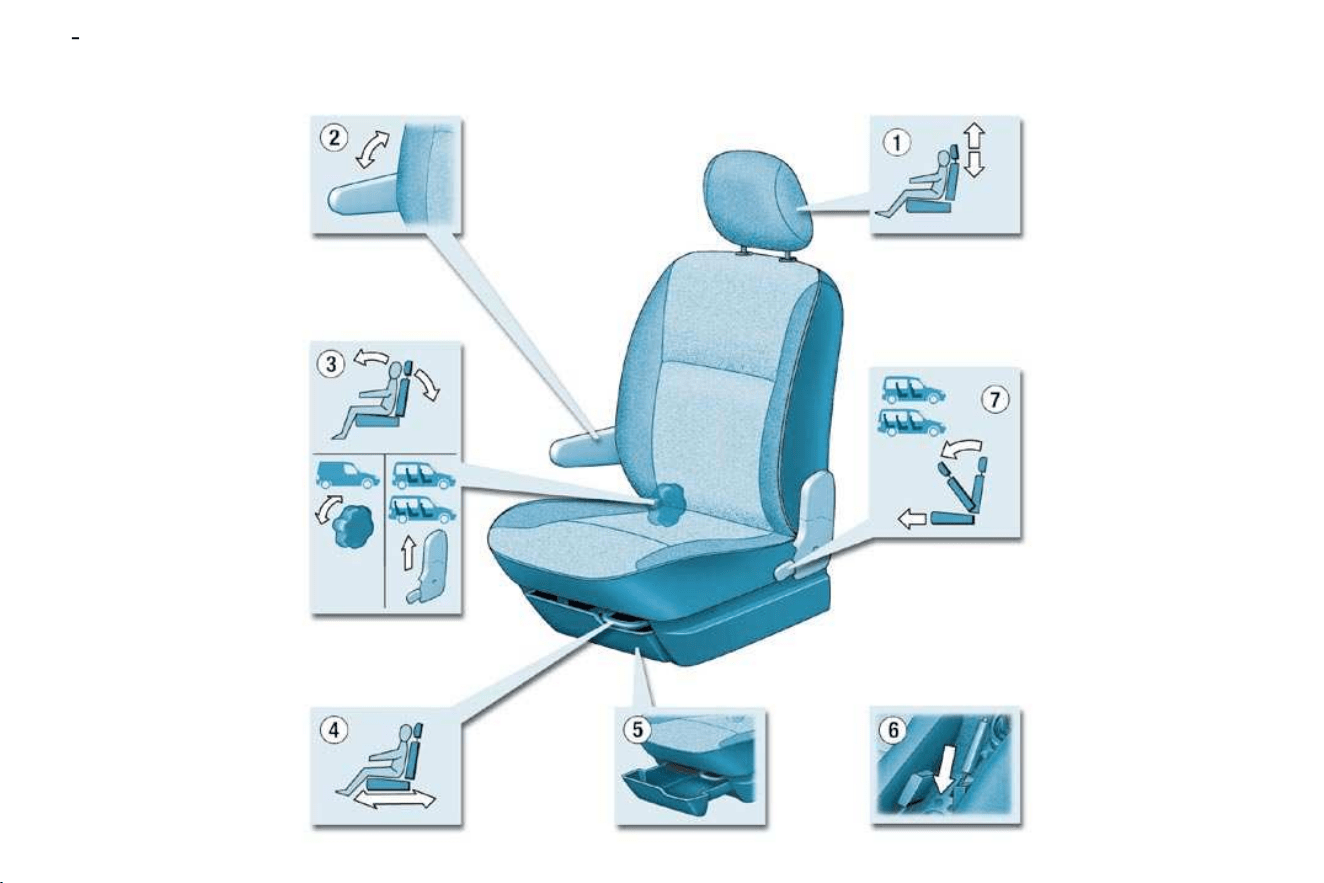
FRONT SEATS
Never travel with the head
restraints removed.
2. Armrest.
3. Seat back angle adjustment.
4. Forwards-backwards adjustment.
5. Storage drawer
(passenger).
40
1. Head restraint height adjustment.

9
FAMILIARISATION
-
REAR BENCH SEATS
(7 SEAT VERSION)
Disarming the passenger air bag
With the ignition off , insert the
ignition key into the passenger
air bag switch 1 and turn it to the
"OFF" position.
As soon as you remove the child
seat, turn the air bag switch to the
"ON" position to activate the air
bag again.
Disarming check
With the ignition switched on
(2 nd notch), illumination of
this warning light indicates
that the passenger air bag
is disarmed (switch in the
"OFF" position).
The warning light remains on through-
out the duration of disarming.
79
Front air bags
These are folded in the centre of the
steering wheel for the driver and in the
fascia for the front passenger. They are
deployed simultaneously, except in cases
where the passenger air bag is disarmed.
Precautions regarding the
passenger air bag
disarm the air bag if you install a
rear-facing child seat,
activate the air bag for an adult
passenger.
78
Side air bags *
Side air bags are incorporated into the
front seat back frame, on the door side.
They are deployed independently of
each other, on whichever side the
collision occurs.
44
The 7 seat version is fi tted with a
2-seat bench in row 2 and a 3-seat
bench in row 3.
* According to version.

FAMILIARISATION
10 -
STEERING WHEEL HEIGHT
ADJUSTMENT
When stationary, push the control
A forwards to unlock the steering
wheel.
Adjust the height of the steering
wheel.
Lock it by pulling control A towards
you fully.
ELECTRIC WINDOWS
1. Driver's electric window.
2. Passenger's electric window.
EXTERIOR MIRRORS
Move the manual control 3 in all
four directions to adjust.
Electric control for the
passenger's side mirror
From the driver's seat, adjust in
all four directions by operating
the control 4 .
Manual mode:
Press the switch. The window
stops as soon as the switch is re-
leased.
Automatic mode (driver):
Press and hold the switch. One
touch completely opens or closes
the window.
64 65 68

11
FAMILIARISATION
-
SPEED LIMITER *
CRUISE CONTROL *
75 73
If the vehicle is fi tted with
a speed limiter and cruise
control, these functions can-
not be activated at the same
time.
This limiter indicates the status of
selection of the function on the in-
strument panel and displays the
programmed speed. The minimum
speed which can be programmed is
at least 18 mph (30 km/h).
It prevents exceeding of the speed
programmed by the driver, this func-
tion remains active regardless of any
action on the brake or clutch pedals.
On the other hand, pressing the ac-
celerator pedal to the point of resist-
ance does not have any effect.
It is possible to exceed the programmed
speed temporarily by pressing the acce-
lerator fi rmly beyond this point of resist-
ance.
The operating actions must be carried
out with the engine running.
The cruise control has a display on
the instrument panel to indicate the
programmed reference speed.
It enables the vehicle to maintain the
reference speed programmed by the
driver.
In order for it to be programmed or
activated, the vehicle speed must be
greater than 25 mph (40 km/h) with
at least fourth gear engaged.
* According to version.

FAMILIARISATION
12 -
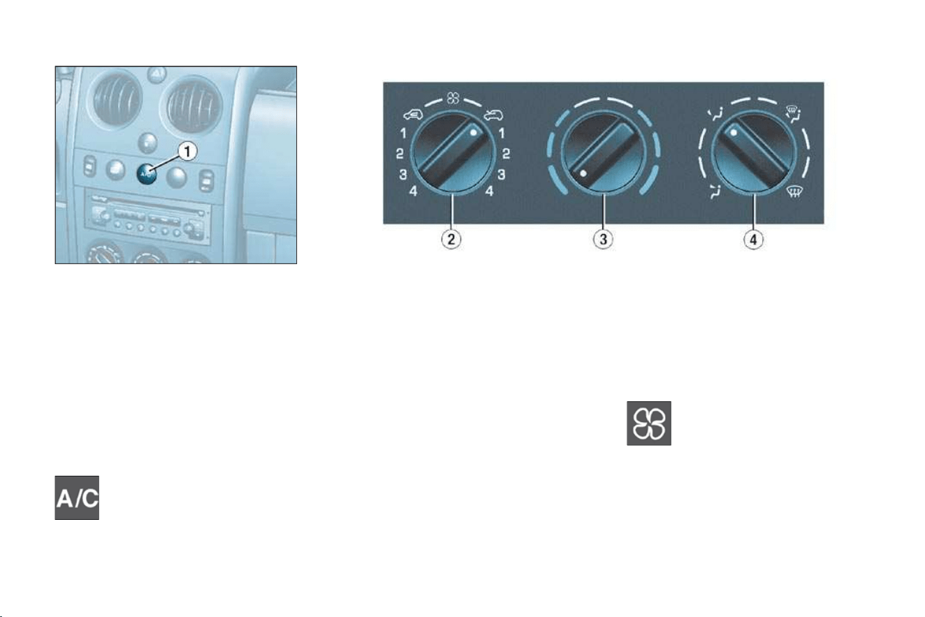
N° Symbol Function
1
Air fl ow adjustment.
2
Air fl ow adjustment
and air intake
control.
3
Temperature
adjustment.
4
Air distribution
adjustment.
N° Symbol Function
1
Air conditioning
control.
2
Air fl ow adjustment
and air intake
control.
3
Temperature
adjustment.
4
Air distribution
adjustment.
36
38
HEATING
AIR CONDITIONING
13
FAMILIARISATION
-
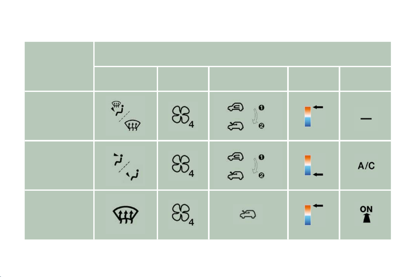
RECOMMENDED INTERIOR SETTINGS
I require...
Heating or Manual air conditioning
Air distribution Air fl ow
Air recirculation/
Intake of exterior air
Temperature Manual AC
HOT
COLD
DEMISTING
DE-ICING

FAMILIARISATION
14 -
FRONT LAYOUT
1.
Storage compartments in the doors.
A. Bottle holder.
B. Can holder.
C. Storage compartment.
2. Overhead storage.
3. Map reading light.
4. Courtesy light.
5. Sun visors.
6. Glove box.
7. Lighter.
8. Removable ashtray.
9. Storage drawer (passenger).
67

15
FAMILIARISATION
-
REAR LAYOUT
Stowing rings
For greater safety, always en-
sure that the loads transported
are secured fi rmly.
69
1. Load space cover.
2. High load retaining net.
3. Stowing rings.
4. Side door storage compartment.
5. Trays between the front and rear
seats.
6. Seat back storage pockets.
70

FAMILIARISATION
16 -
This operation must be carried out
with the engine switched off .
Insert the key then turn it to the
left.
Remove the cap.
A label indicates which type of fuel to
use.
When you fi ll your tank, do not continue
after the third cut-off of the pump. This
could cause engine malfunctions.
The capacity of the tank is approx-
imately 55 litres for petrol engines
and 60 litres for Diesel engines.
From the time this light comes on,
you have enough fuel left to cover
approximately 30 miles (50 km) .
Note: the right-hand sliding side door
cannot be opened while the fuel tank
cap is removed.
Outside the vehicle: Lift the control,
raise the bonnet and secure the strut
to keep the bonnet open.
OPENING THE BONNET
Inside the vehicle: Pull the control
on the left-hand side, under the fascia
panel.
Low fuel level
warning light
61 61
FILLING WITH FUEL

MONITORING and DISPLAY SCREENS
18 -
1. Seat belt not fastened warning
light
2. Front and side air bags warning
light
3. Passenger air bag disarmed
warning light
4. Front fog lamps indicator light
5. Anti-lock braking system (ABS)
warning light
6. Rear fog lamp indicator light
7. Diesel pre-heat warning light
8. Left hand direction indicator
9. Total distance recorder, service
indicator and engine oil level
indicator
10. Right hand direction indicator
11. Emission control system warning
light
12.
Main beam headlamps indicator light
13. Handbrake, low brake fl uid
level and electronic brake force
distribution warning light
14. Dipped beam headlamps
indicator light
15. Battery charge warning light
16. Engine oil pressure and
temperature warning light
17. Water in diesel fi lter warning light
18. Low coolant level warning light
19. Coolant temperature indicator
20. Total distance recorder button
21. Central (STOP) warning light
22. Speedometer
23. Rev counter
24. Lighting rheostat button
25. Fuel level indicator
26. Low fuel level warning light
27. Speed limiter/cruise control
display
INSTRUMENT PANEL: PETROL - DIESEL

19
MONITORING and DISPLAY SCREENS
-
INSTRUMENTS AND
CONTROLS
A permanently lit warning light or
one fl ashing, with the engine run-
ning, indicates an operating fault
of the unit concerned. The illumi-
nation of certain warning lights
may be accompanied by an audi-
ble signal and a message on the
display. Do not ignore this warn-
ing: consult a CITROËN dealer as
soon as possible.
If the central STOP warning light
comes on when you are driving,
stop your vehicle immediately,
where it is safe to do so.
Central (STOP)
warning light
Linked to the warning
lights:
- ''engine oil pressure and tempe-
rature'',
- ''low coolant level'',
- 'handbrake'',
- ''low brake fl uid level'',
- ''electronic brake force distribution
system fault''.
Linked with the "coolant temperature"
indicator.
You must stop if the light fl ashes
with the engine running.
Consult a CITROËN dealer.
Engine oil pressure
and temperature
warning light
Linked to the central (STOP) warning
light.
You must stop.
This warning light indicates one of
the following:
- insuffi cient oil pressure indicated
by the message "Oil pressure
insuffi cient" on the display.
- a lack of oil in the lubrication circuit.
Top up the level.
- an oil temperature which is too
high. To lower the oil temperature,
reduce your speed.
Lighting of the warning light is ac-
companied by an audible signal.
Consult a CITROËN dealer.
Low engine coolant
level warning light
Linked to the central (STOP)
warning light.
This comes on for a few seconds
when the ignition is switched on.
Lighting of this warning light is ac-
companied by an audible signal and
the message "Top up engine fl uid
level" on the display.
You must stop.
Wait for the engine to cool before
topping up the level.
The cooling circuit is pressurised.
Handbrake, low
brake fluid level and
Electronic Brake Force
Distribution system
fault warning light
Linked to the central (STOP) warning
light.
This comes on each time the ignition
is switched on.
Lighting of this warning light is ac-
companied by an audible signal and
a message on the display indicating
the cause of the warning:
- "Handbrake on", if the handbrake
is applied or not fully released.
- "Brake fl uid level low" if there is
an excessive drop in brake fl uid
level (if the warning light remains
on even when the handbrake is
released).
- "Braking fault" is displayed to-
gether with the ABS warning
light, indicating a malfunction of
the Electronic Brake Force Distri-
bution system. You must stop.
Consult a CITROËN dealer.
In the event of breakdown and to
prevent any risk of burns, un-
screw the cap by two turns to allow
the pressure to drop.
When the pressure has dropped, re-
move the cap and top up the level.
Consult a CITROËN dealer.

MONITORING and DISPLAY SCREENS
20 -
Battery charge warning
light
This comes on for a few se-
conds when the ignition is
switched on. Lighting of this warning
light, when the engine is running, ac-
companied by an audible signal and
the message "Battery charge fault"
on the display, indicates one of the
following:
- faulty operation of the charging
circuit,
- slack battery or starter terminals,
- a cut or slack alternator belt,
- an alternator failure.
Consult a CITROËN dealer.
Emission control
system warning light
This comes on for a few
seconds each time the igni-
tion is switched on.
If it comes on with the engine running,
accompanied by an audible signal
and the message on the display:
- "Antipollution fault", this indi-
cates a failure of the emission
control system .
- "Catalytic converter fault", this
indicates a malfunction of the in-
jection or ignition system. There
is a risk of damage to the catalytic
converter (petrol engine only).
Consult a CITROËN dealer.
Diesel engine
pre-heat warning
light
Wait until the warning light goes out
before starting the engine.
If the temperature is high enough,
the warning light comes on for less
than one second. You can start the
engine without waiting.
Low fuel level
warning light
This comes on for a few
seconds when the igni-
tion is switched on.
When the ignition is on, it is accom-
panied by an audible signal and the
message "Fuel level low" on the
display.
If it fl ashes with the fuel gauge needle
in the lowest position, when the igni-
tion is on, this indicates a malfunction
of the fuel gauge.
When this warning light fi rst comes
on, you have enough fuel left to drive
approximately 30 miles (50 km) .
Capacity of the tank:
- approximately 55 litres for petrol
engines,
- approximately 60 litres for Diesel
engines.
Water in diesel filter
indicator *
There is a risk of damage to the
injection system.
Consult a CITROËN dealer as soon
as possible.
Anti-lock braking
system (ABS) warning
light
This comes on for a few seconds each
time the ignition is switched on.
If the warning light remains on or
comes on above 8 mph (12 km/h),
this indicates an ABS malfunction.
However, the vehicle retains conven-
tional servo-assisted braking.
Lighting of this warning light, accom-
panied by an audible signal and the
message "ABS fault" on the display,
indicates an ABS fault.
Consult a CITROËN dealer.
* According to country.
21
MONITORING and DISPLAY SCREENS
-
Seat belt not fastened
warning light *
When the ignition is switched
on, this indicator light comes
on if the driver has not fastened his
seat belt.
Above 12 mph (20 km/h), the warn-
ing light fl ashes for two minutes.
Once the two minutes have elapsed,
the warning light remains on until the
driver fastens his seat belt.
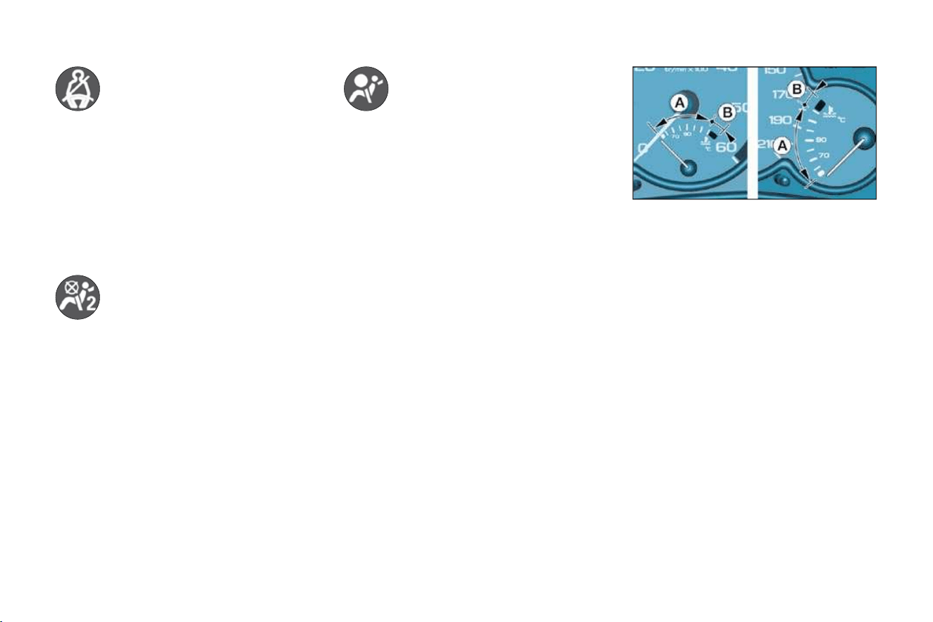
Coolant temperature indicator
- needle in zone (A) , the tempera-
ture is correct,
- needle in zone (B) , the tempera-
ture is too high. The central STOP
warning light fl ashes, accompa-
nied by an audible signal and the
message "Engine coolant temp.
too high" on the display.
You must stop.
Consult a CITROËN dealer.
* According to country.
Passenger air bag
disarmed warning
light *
Lighting of this warning light is accom-
panied by the message "Passenger
air bag deactivated" on the display.
If the passenger air bag is disarmed,
the warning light comes on when
the ignition is switched on and it re-
mains on.
Always consult a CITROËN dealer if
the warning light fl ashes.
Front and side air bags
warning light
This comes on for a few
seconds when the ignition is
switched on.
With the engine running, illumination
of this warning light accompanied by
an audible signal and the message
"Air bag fault" on the multifunction
display, indicates a fault in the air
bags.
Consult a CITROËN dealer.

21
MONITORING and DISPLAY SCREENS
-
Seat belt not fastened
warning light *
When the ignition is switched
on, this indicator light comes
on if the driver has not fastened his
seat belt.
Above 12 mph (20 km/h), the warn-
ing light fl ashes for two minutes.
Once the two minutes have elapsed,
the warning light remains on until the
driver fastens his seat belt.
Coolant temperature indicator
- needle in zone (A) , the tempera-
ture is correct,
- needle in zone (B) , the tempera-
ture is too high. The central STOP
warning light fl ashes, accompa-
nied by an audible signal and the
message "Engine coolant temp.
too high" on the display.
You must stop.
Consult a CITROËN dealer.
* According to country.
Passenger air bag
disarmed warning
light *
Lighting of this warning light is accom-
panied by the message "Passenger
air bag deactivated" on the display.
If the passenger air bag is disarmed,
the warning light comes on when
the ignition is switched on and it re-
mains on.
Always consult a CITROËN dealer if
the warning light fl ashes.
Front and side air bags
warning light
This comes on for a few
seconds when the ignition is
switched on.
With the engine running, illumination
of this warning light accompanied by
an audible signal and the message
"Air bag fault" on the multifunction
display, indicates a fault in the air
bags.
Consult a CITROËN dealer.

MONITORING and DISPLAY SCREENS
22 -
Service indicator
This is a visual reminder of when the
next service is due. This service is to
be carried out according to the manu-
facturer's servicing schedule.
5 seconds after the ignition is switched
on, the total distance recorder resumes
normal operation and the display shows
the total or trip distances.
The distance remaining before the next
service is less than 500 miles (1,000 km).
Example: 400 miles (900 km) remain
before the next service is due.
When switching on the ignition and
for 5 seconds, the display shows:
5 seconds after the ignition is
switched on, the total distance re-
corder resumes normal operation
and the symbol remains lit.
This indicates that a service should
be carried out shortly. The display
shows the total or trip distances.
The service is overdue.
Each time the ignition is switched on
and for 5 seconds, the symbol and
the excess distance fl ash.
Example: the service is overdue by
300 miles/km. The service should be
carried out very shortly.
When the ignition is switched on and
for 5 seconds, the display shows:
5 seconds after the ignition is
switched on, the total distance re-
corder resumes normal operation and
the symbol remains lit. The display
shows the total or trip distances.
Note: the spanner lights if the two-year
interval has been exceeded.
INSTRUMENT PANEL
DISPLAY
After switching on the ignition, three
functions are shown in succession:
- service indicator,
- engine oil level indicator,
- total distance recorder/total and
trip distances.
Note : the total and trip distances are
displayed for 30 seconds when the
ignition is switched off, on opening
the driver's door, as well as on lock-
ing and unlocking the vehicle.
Example: 4,800 miles/km remain be-
fore the next service is due. When the
ignition comes on and for 5 seconds
the display shows:
Operation
As soon as the ignition is switched
on and for 5 seconds, the spanner
symbolising ''service operation'' is lit.
The trip recorder display shows the
distance remaining (in round fi gures)
before the next service.

23
MONITORING and DISPLAY SCREENS
-
Engine oil level indicator
When the ignition is switched on,
the engine oil level is indicated for
approximately 10 seconds, after the
service information.
Flashing of the six squares and dis-
playing of "max" indicate a surplus of
oil which could damage the engine.
If the surplus of oil is confi rmed by
a check using the dipstick, contact a
CITROËN dealer without delay.
Your CITROËN dealer carries out
this operation after each service.
The reset procedure is as follows:
- Switch off the ignition.
- Press and hold button 1 .
- Switch on the ignition.
The display begins a 10 second count-
down.
-
Keep button 1 pressed for 10 seconds.
The display shows [=0] and the spanner
disappears.
Flashing of the six segments and dis-
playing of "min" indicate a lack of oil
which could damage the engine.
If the lack of oil is confi rmed by a
check using the dipstick, it is essential
that the level is topped up.
Flashing of the six segments indi-
cates a malfunction of the oil level
indicator.
There is a risk of damage to the
engine.
Consult a CITROËN dealer.
The level read on the dipstick or on
the indicator will only be correct if
the vehicle is on level ground and
the engine has been off for more
than 15 minutes.
Resetting the service indicator
Surplus of oil
Lack of oil
Oil level indicator fault

MONITORING and DISPLAY SCREENS
24 -
Briefl y pressing button 1 alternates
between the total and trip distance
displays.
To reset the trip recorder to zero,
when it is displayed press button 1
until zeros appear.
Total distance recorder
With the lights on, press the button
to vary the intensity of the lighting of
the instruments and controls. When
the lighting reaches the minimum (or
maximum) setting, release the button
then press it again to increase (or re-
duce) the brightness.
As soon as the lighting is of the re-
quired brightness, release the button.
LIGHTING RHEOSTAT
CLOCK
Button 1 : hour adjustment
Button 2 : minute adjustment
Press and hold the button for rapid
advance.

25
MONITORING and DISPLAY SCREENS
-
DISPLAY A
This displays the following information:
- the time,
- the date,
- the audio system displays,
- a door check (e.g.: ''left front door
open''),
- warning messages (e.g. ''remote
control battery fl at'') or information
messages (e.g. ''economy mode
active''), displayed temporarily.
Adjusting the parameters display A
Press and hold button A for two
seconds to access the settings; the
data fl ashes, indicating it is ready to
be modifi ed.
Then, each press of button A scrolls
through the various data in the follow-
ing order:
- language of information displayed,
- hours (12 then 24 hour mode),
- minutes,
- year,
- month,
- day.
Pressing button B alters the value of
the parameter selected. Press and
hold for rapid advance (return to start
after the last possible value).
After 7 seconds with no action, the
standard display returns; the modifi ed
data is now recorded.
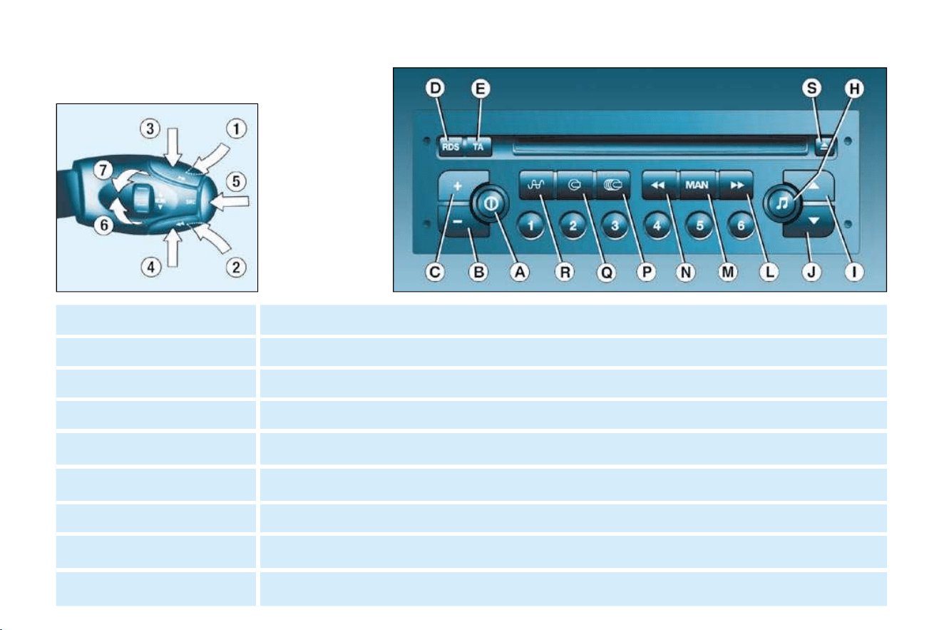
AUDIO
26 -
AUDIO RD3
Stalk movement Function
1 - Press (behind) Increase volume
2 - Press (behind) Decrease volume
1 + 2 - Simultaneous press Sound cut-off (mute); restoring of the sound by pressing any button
3 - Press Automatic search of higher frequencies (radio). Selection of the next track (CD)
4 - Press Automatic search of lower frequencies (radio). Selection of the previous track (CD)
5 - Press the end Change of source (radio/CD)
6 - Rotation (clockwise) Selection of next station stored in memory (radio)
7 - Rotation (anti-clockwise) Selection of previous station stored in memory (radio)
27
AUDIO
-
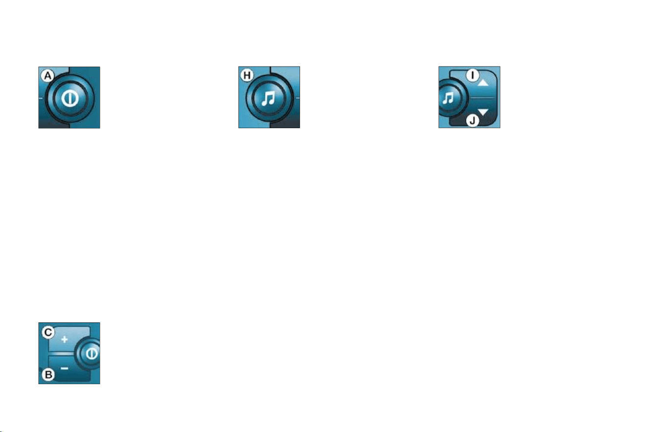
Button Function
A
Radio on/off.
B - Decrease volume.
C + Increase volume.
D RDS
RDS function on/off.
Press for more than 2 seconds: regional following mode on/off.
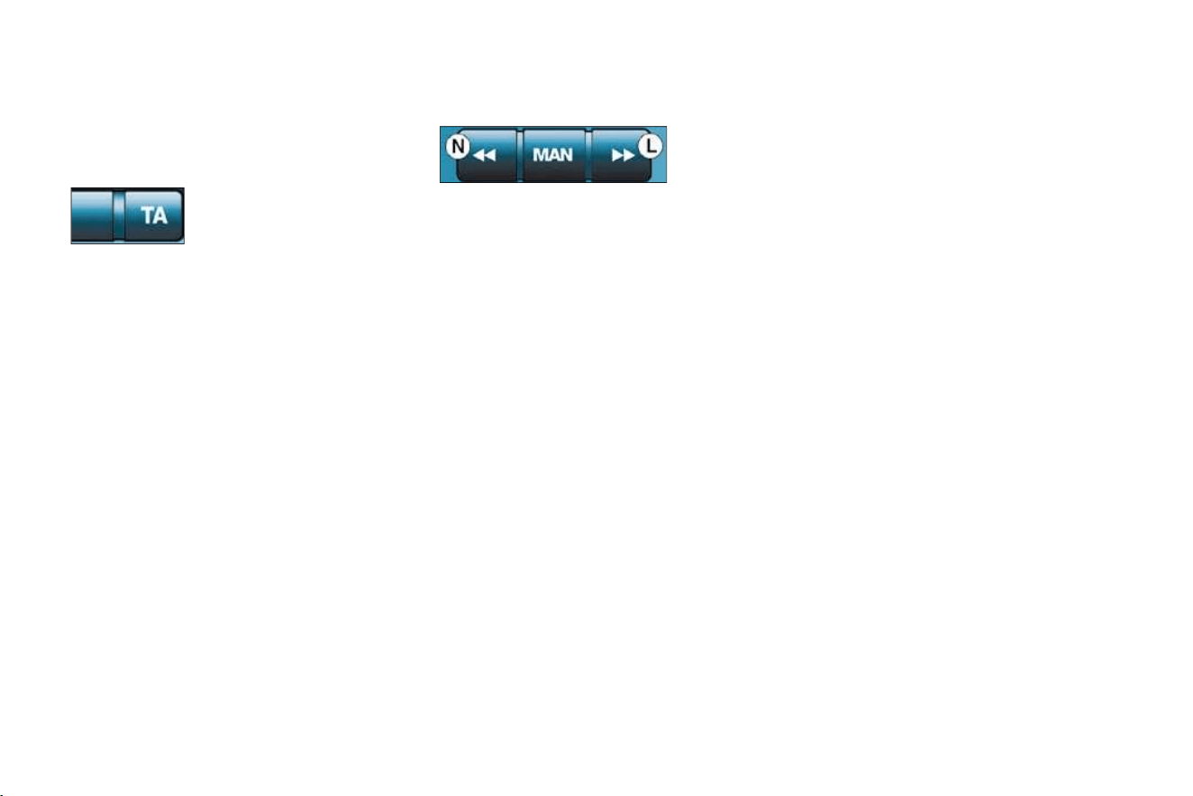
E TA
Traffi c information priority on/off.
Press for more than 2 seconds: PTY function on/off.
H
Selection of bass, treble, loudness, sound distribution and automatic volume correction.
I
Increase the setting of the functions associated with button H .
J
Decrease the setting of the functions associated with button H .
L
Manual and automatic search of higher frequency.
Selection of next CD track and PTY (radio).
M MAN Manual/automatic operation of buttons L and N .
N
Manual and automatic search of lower frequency.
Selection of previous CD track and PTY (radio).
Q CD
Selection of CD.
Press for more than 2 seconds: shuffl e.
R Radio
Selection of radio. Selection of FM1, FM2, FMast and AM wavebands.
Press for more than 2 seconds: automatic storing of stations in memory (autostore).
S
Ejection of CD.
1 to 6 12 34 56
Selection of station stored in memory.
Press for more than 2 seconds: storing of a station in memory.
AUDIO
28 -
GENERAL FUNCTIONS
AUDIO SETTINGS
Adjusting the loudness
This function automatically empha-
sises bass and treble tones. Press
button I or J to switch the function on
or off.
On/off
With the ignition key
in the accessories or
ignition position, press
button A to switch the
set on or off.
The set can oper-
ate for 30 minutes
without the vehicle ignition being
switched on.
Anti-theft system
The audio system is coded in such a
way that it can operate only on your
vehicle. It would not function if fi tted
to another vehicle.
The anti-theft system is automatic
and requires no action on your part.
ADJUSTING THE VOLUME
Adjusting the bass
Adjusting the treble
When "TREB" is displayed, press
button I or J to vary the setting.
- "TREB -9" for a minimum treble
setting,
- "TREB 0" for a normal setting,
- "TREB +9" for a maximum treble
setting.
Press button H sev-
eral times in succes-
sion to access the
bass (BASS) , treble
(TREB) , loudness
(LOUD) , fader (FAD) ,
balance (BAL) and
automatic volume cor-
rection.
Exit from audio mode is automatic
after a few seconds without pressing
any button, or by pressing button H
after confi guration of the automatic
volume correction.
Note: bass and treble settings are
specifi c to each source. It is pos-
sible to set them differently for radio,
cassette (RB3) , CD (RD3) and CD
changer.
When "BASS" is dis-
played, press button
I or J to vary the set-
ting.
- "BASS -9" for a
minimum bass
setting,
- "BASS 0" for a normal setting,
- "BASS +9" for a maximum bass
setting.
Press button C to in-
crease the volume, or
button B to decrease it.
Continuous pressure on
buttons C and B allows
a gradual adjustment of
the volume.

29
AUDIO
-
RADIO
Adjusting the front/rear sound
distribution (Fader)
When "FAD" is displayed, press but-
ton I or J .
Button I increases the volume in the
front.
Button J increases the volume in the
rear.
Adjusting the right/left sound
distribution (Balance)
When "BAL" is displayed, press but-
ton I or J .
Button I increases the volume on the
right-hand side.
Button J increases the volume on the
left-hand side.
Automatic volume correction
This function enables the volume to
be automatically adjusted depending
on the level of noise produced by the
speed of the vehicle.
Press buttons I or J to switch the
function on or off.
Selecting radio mode
Press button R . Notes on radio reception
Your car radio is subject to phenom-
ena which do not affect domestic ra-
dio sets. Both AM (MW/LW) and FM
reception are subject to various forms
of interference. This is no refl ection on
the quality of the equipment, but is due
to the nature of the signals and the way
in which they are transmitted.
On MW/LW, interference may be
noticed when passing under high
voltage power lines or bridges, or in
tunnels.
On FM, interference may be the result
of increasing distance from the trans-
mitter, defl ection of the signals by ob-
stacles (mountains, hills, buildings,
etc.), or of being in an area which is
not covered by a transmitter.
Selecting a waveband
Briefl y press button R to select the
FM1, FM2, FMast and AM wave-
bands.

AUDIO
30 -
Briefl y press button L or N to search
for the station immediately above or
below. By continuing to press the
button in the direction selected, you
will obtain continuous scrolling of the
frequency.
The scrolling stops at the fi rst sta-
tion found as soon as the button is
released.
If the TA traffi c information pro-
gramme is selected, only stations
broadcasting this type of programme
are selected.
Searching for a station occurs fi rst in
"LO" sensitivity (selection of the most
powerful transmitters) during scan-
ning of the waveband, then in "DX"
sensitivity (selection of the weakest
and most distant transmitters).
To make a direct search in "DX" sen-
sitivity, press button L or N twice.
Manual station search
Press the "MAN" button.
Briefl y press button L or N to in-
crease or decrease the frequency
displayed.
By continuing to press the button in
the direction selected, you will obtain
continuous scrolling of the frequency.
The scrolling stops at the fi rst sta-
tion found as soon as the button is
released.
Pressing the "MAN" button again re-
turns you to automatic station search.
Manual storing of stations
in the memory
Select the station required.
Press one of the buttons "1" to "6"
for more than two seconds.
The sound stops then becomes audi-
ble again, confi rming that the station
has been stored in the memory.
Automatic station search Automatic storing of FM stations
in the memory (autostore)
Press and hold button
R for more than two
seconds.
Your radio automatically stores the
6 stations with the strongest signal
in FM . These stations are stored in
the FMast waveband.
If it is not possible to fi nd 6 stations,
the remaining memories are empty.
Recalling stations stored
in the memory
For each waveband, briefl y press
buttons "1" to "6" to recall the cor-
responding station.

31
AUDIO
-
RDS
Traffi c information programme Regional following mode (REG)
RDS station following
The display indicates the name of the
station selected. The radio is contin-
ually searching for the station which
has the best reception and which is
transmitting the same programme.
Press the "TA" button
to switch the function
on or off.
Briefl y press the "RDS"
button to switch the
function on or off.
The multi-function display will show:
- "RDS" if the function is selected.
- "(RDS)" if the function is selected
but not available.
When they are part
of a network, certain
stations broadcast re-
gional programmes in
the various areas they serve. With re-
gional following mode you can keep
listening to the same programme.
Press the "RDS" button for more
than two seconds to switch the REG
function on or off.
Using the RDS (Radio Data
System) function on FM
Radio Data System allows you to
continue listening to the same sta-
tion, whatever frequency it is using
for the region you are going through.
Note: the volume of traffi c informa-
tion announcements is indepen-
dent of the volume of normal radio
listening. You can adjust it using
the volume button. The setting will
be stored and will be used when
the next messages are broadcast.
The multi-function display will show:
- "TA" if the function is selected,
- "(TA)" if the function is selected
but not available.
Any traffi c information fl ash will be
given priority, whatever source you
are listening to (radio, cassette, CD
or CD changer).
If you wish to interrupt a message,
press the "TA" button; this switches
the function off.
AUDIO
32 -
EON system
This connects stations which are part
of the same network. It enables the
broadcast of traffi c information, by a
station that is part of the same net-
work as the station to which you are
listening.
This service is available when you
have selected the TA traffi c informa-
tion programme or the PTY function.
PTY function
This allows you to listen to stations broad-
casting a specifi c type of programme
(news, culture, sport, rock, etc.).
To search for a PTY programme:
With FM selected,
press the "TA" but-
ton for more than two
seconds to switch this
function on or off.
- select the PTY function,
- briefl y press button L or N to
scroll down the list of the various
types of programmes offered.
- when the programme of your
choice is displayed, keep button L
or N pressed for more than two
seconds to carry out an automatic
search (after an automatic search
the PTY function is switched off).
In PTY mode the different types of
programmes can be stored in the
memory. To do this, press the pre-
selection buttons "1" to "6" for more
than two seconds. Briefl y press the
corresponding button to recall the
type of programme stored in the
memory.

33
AUDIO
-
Ejection of a disc
Shuffl e
When the CD player is selected, keep
button Q pressed for two seconds.
The tracks will be played in random
sequence. Pressing the button again
for two seconds returns you to nor-
mal play.
Shuffl e mode is de-activated each
time the audio system is switched off.
After insertion of a
disc, printed face
upwards, the player
starts automatically.
If a disc is already inserted, press
button Q .
COMPACT DISC
The use of copied compact
discs may cause faults.
Insert circular compact discs
only.
Selecting a track
Press button L to select the next
track.
Press button N to return to the start
of the current track or to select the
previous track.
Press button S to
eject the disc from the
player.
Accelerated play
Keep button L or N pressed for for-
wards or backwards accelerated play.
Accelerated play stops as soon as
the button is released.
Selecting CD mode

COMFORT
34 -

35
COMFORT
-
VENTILATION
1. Windscreen de-icing or
demisting vents.
2. Front window de-icing or
demisting vents.
3. Side vents.
4. Centre vents.
5. Air outlets to front footwells.
The air conditioning system does not
contain chlorine and does not present
any danger to the ozone layer.
Operate the air conditioning system
for 5 to 10 minutes, once or twice a
month, to keep it in perfect working
order.
The water created by the air condi-
tioning condensation is discharged
via an opening provided for this pur-
pose. Therefore, a puddle of water
may form underneath the vehicle
when stationary.
If the system does not produce
cold air, do not use it and contact a
CITROËN dealer.
De-icing the rear windows and
mirrors
With the engine running, pressing
the control de-ices the rear windows
and mirrors.
It switches off automatically after ap-
proximately twelve minutes.
Pressing the control again switch-
es the de-icing system on again for
twelve minutes.
It is possible to switch off the de-
icing by pressing the control before
the twelve minutes have elapsed.
Advice on operation
Select the air distribution most suited
to your requirements and the climatic
conditions.
Gradually adjust the temperature
setting for your comfort.
Position the air control in the ''Outside
Air'' position.
For perfectly even air distribution,
take care not to obstruct the exterior
air intake grille and the vents. Check
that the passenger compartment fi lter
is in good condition.
When the engine is cold, to prevent
too great a distribution of cold air, the
ventilation will increase to its opti-
mum level gradually.
In order to be effective, the air condi-
tioning ( A/C button), should only be
used with the windows closed.
If the interior temperature remains
very high following a prolonged period
parked in the sun, do not hesitate to
ventilate the passenger compartment
for a few minutes.

COMFORT
36 -
Intake of exterior air.
HEATING
Turn the control from posi-
tion 1 to position 4 to obtain
an air fl ow suffi cient to en-
sure your comfort.
2. Air fl ow adjustment and air
intake control
Turn the control from posi-
tion 1 to position 4 to obtain
an air fl ow suffi cient to en-
sure your comfort.
As soon as possible, position the
control in the exterior air intake
position to prevent misting of the
windows.
This is the normal operating position.
Passenger compartment
isolation.
This position prevents exterior odours
and smoke entering the passenger
compartment.
1. Air fl ow adjustment

37
COMFORT
-
These settings are recommended for
cold climates.
3. Temperature adjustment
To be adjusted to your requirements.
From blue (exterior temperature) to
red (hot).
4. Air distribution adjustment
This setting is recommended for high
temperatures.
Windscreen and side windows
(de-icing/demisting).
To quickly de-ice or demist the wind-
screen and side windows:
- position the air intake control in
the ''Outside Air" position,
- turn the temperature and air fl ow
controls to maximum,
- close the centre vents.
Windscreen, side windows
and footwells.
Footwells.
Centre and side vents.
COMFORT
38 -
Press the switch to activate
the air conditioning. The indi-
cator light comes on.
2. Air fl ow adjustment and air
intake control
Turn the control from posi-
tion 1 to position 4 to obtain
an air fl ow suffi cient to en-
sure your comfort.
AIR CONDITIONING
The air conditioning does not
operate while the air fl ow adjust-
ment control is in the minimum
position.
Note: to optimise the operation of
the air conditioning, leave the vents
open.
1. Air conditioning control
The air conditioning is designed to
operate in all seasons. In summer,
it enables the temperature to be
lowered and in winter, above 0 °C,
it increases the effectiveness of the
demisting.

39
COMFORT
-
Additional heater
Vehicles which are fi tted with an HDI
engine may be fi tted with automatic
additional heating to improve your
comfort.
When the engine is idling or the vehi-
cle is stationary, it is quite normal to
notice a high-pitched whistling noise
and a slight emission of smoke and
odour.
Centre and side vents.
This setting is recommended for high
temperatures.
Recirculation of interior air.
This position prevents exterior odours
and smoke entering the passenger
compartment.
Used simultaneously with the air con-
ditioning, recirculation enables both
heating and cooling performance to
be improved.
Used without the air conditioning,
recirculation may result in misting of
the windows.
As soon as possible, position the
control in the exterior air intake posi-
tion.
3. Temperature adjustment
To be adjusted to your requirements.
From blue (cold when the air condi-
tioning is on) to red (hot).
4. Air distribution adjustment
Windscreen and side windows
(de-icing/demisting).
To quickly de-ice or demist the wind-
screen and side windows:
- turn the temperature and air fl ow
controls to maximum,
- close the centre vents,
- position the air intake control in
the "Outside Air" position,
- start the air conditioning.
Footwells.
These settings are recommended for
cold climates.
Windscreen, side windows
and footwells.
Intake of exterior air.
This is the normal operating position.
SEATS
40
-
41
SEATS
-
FRONT SEATS
The adjustment is correct when
the upper edge of the head re-
straint is level with the top of the
head.
To remove the head restraint, place it
in the top position, press the tabs and
pull it upwards.
To put it back in position, locate the
stems of the restraint in the holes,
taking care to keep them in line with
the seat back.
No person or object must pre-
vent the seat from returning
to its initial position; return to
this position is necessary for
the seat to lock in place.
4. Forwards-backwards
adjustment
Lift the control and slide the seat for-
wards or backwards.
1. Head restraint height
adjustment
To raise or lower the restraint, slide it.
2. Armrests
These can be folded back.
3. Seat back angle adjustment
5. Storage drawer (version with
passenger air bag)
There is a storage drawer under the
front passenger seat.
To open it, lift it and pull.
6. Heated seats switch
Press the switch. The temperature is
controlled automatically.
Pressing the switch again stops op-
eration.
Note: the command for activation of
heating of the seat(s) remains memo-
rised for two minutes after the ignition
has been switched off.
7. Access to rear seats
(version with one
sliding side door only)
Do not place heavy objects
in the drawers.
A. Turn the knob.
B. Pull the lever (version
with one sliding side
door only).
Never drive with the head
restraints removed; they
must be in place and cor-
rectly adjusted.
Lift the control to fold the seat back
and move the seat forwards.
On repositioning, the seat returns to
its initial position (driver's side).
SEATS
42
-
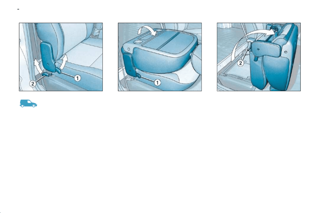
MULTIFUNCTION PASSENGER SEAT
To fold the seat fully:
Pull the control 2 upwards and tilt the
whole seat.
It is not necessary to remove the
head restraint.
This provides access to a box which
enables you to store objects so that
they cannot be seen from outside the
vehicle.
If your vehicle is not fi tted with a load
blocking partition, it can accommo-
date long objects (up to 2.10 m).
These must be placed on the front
edge of the fl oor and secured using
the rear bar of the boot or using the
lashing rings.
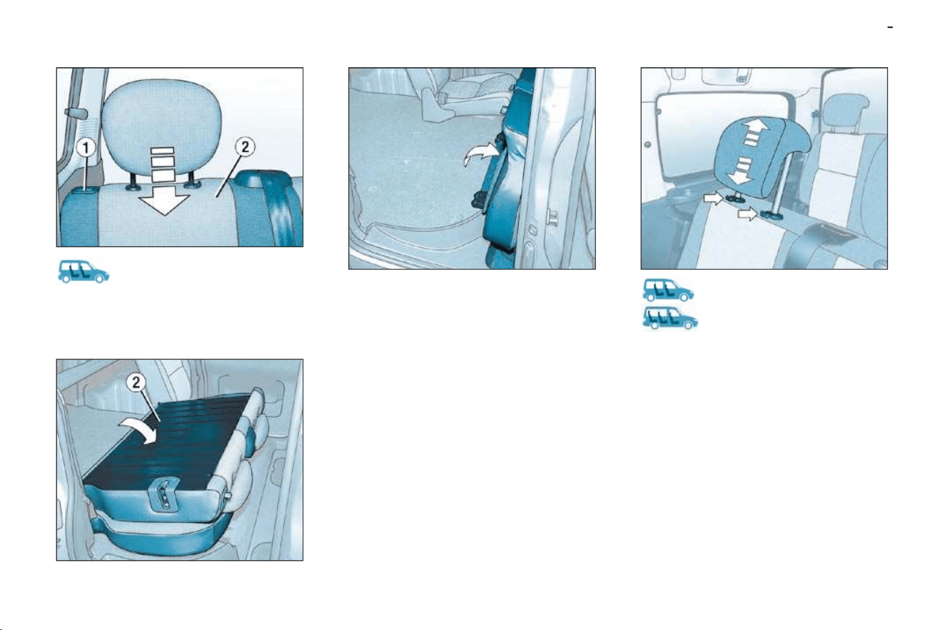
To fold the seat back:
Pull the control 1 upwards and tilt the
seat back.
This provides a fl at surface, recess-
es for drinks and a strap for retaining
documents.
43
SEATS
-
To fold the rear bench seat:
- lower the head restraint,
- press control 1 to unlock the seat
back 2 ,
- fold the seat back 2 onto the seat,
- place the seat in the "folded" posi-
tion.
When repositioning:
- tilt the folded seat rearwards,
- lift the seat back,
- check that the seat is locked cor-
rectly.
Take care not to trap the seat belts.
REAR BENCH SEAT
(5 SEAT VERSION)
HEAD RESTRAINT
This is of the "comma" type.
High position: press the two tabs at
the same time, lift the head restraint
and raise it.
Low position: push the two tabs at
the same time and press the top to
lower the head restraint.
To remove the head restraint: place
it in the high position, lift it then re-
move it.
Store it inside the vehicle, securing
it fi rmly.
To install the head restraint: engage
the rods of the head restraint in the
holes keeping it in line with the seat
back.
SEATS
44
-
REAR BENCH SEATS
(7 SEAT VERSION)
The bench seats of row 2 and row 3
are independent and adjustable.
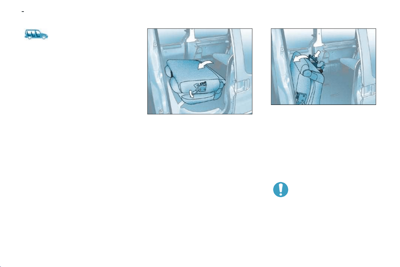
Row 2 bench seat
Placing the bench seat in the
table position
- Lower the head restraints fully.
- Operate the control to fold the
seat back onto the bench seat
cushion.
Returning the seat back to
the sitting position
- Return the seat back to its original
position and check that it is se-
cured on the pillar of the vehicle.
Placing the bench seat in the fully
folded position
- Place the seat in the table posi-
tion.
- Pull the handle, located behind
the bench seat, to release the
feet from their anchorage on the
fl oor.
- Tilt the bench seat forwards.
Returning the bench seat to its
original position
Before folding the bench seat,
ensure that:
- in row 3, no passenger's foot is at
one of the bench seat anchorages
on the fl oor,
- the seat belt is available for the
side passenger.
- fold back the bench seat.

45
SEATS
-
Row 3 bench seat
Placing the seat back in the table
position
- Lower the head restraints fully.
- Operate the two controls simulta-
neously to fold the seat back onto
the bench seat cushion.
Returning the seat back to the
sitting position
- Return the seat back to its original
position and check that it is se-
cured on the pillars of the vehicle.
Placing the bench seat in the fully
folded position
- Place the seat in the table position.
- Raise the handle, located behind
the bench seat, to release the
feet from their anchorage on the
fl oor.
- Tilt the bench seat forwards.
Returning the bench seat to its
original position
- Before folding back the bench
seat, ensure that the seat belt
is available for the side passen-
gers.
- Fold back the bench seat.
Access to row 3
From the vehicle's right-hand sliding
door, a passage next to the row 2
bench seat provides access to the
row 3 bench seat.
Good practice
Do not place hard or heavy
objects on the seat backs
forming a table, they could
become dangerous projectiles in the
event or sharp braking or impact.
Following the various operations:
- do not remove a head restraint
without storing it, fi x it to a sup-
port in the vehicle,
- do not block the passage to row 3,
- ensure that the passengers can
always access the seat belts and
fasten them easily,
- a passenger must never take his
seat without adjusting and fasten-
ing his seat belt.
- a passenger seated in row 3 must
ensure that he does not obstruct
the row 2 bench seat anchoring
recesses.
SEATS
46
-
GENERAL POINTS RELATING
TO CHILD SEATS
Although one of CITROËN's main
criteria when designing your vehicle,
the safety of your children also de-
pends on you.
For maximum safety, please follow
these precautions:
- all children under the age of 12
or less than one metre fi fty tall
must travel in approved child
seats suited to their weight ,
on seats fi tted with a seat belt or
ISOFIX mountings * .
- a child weighing less than 9 kg
must travel in the "rearwards-
facing" position in the front.
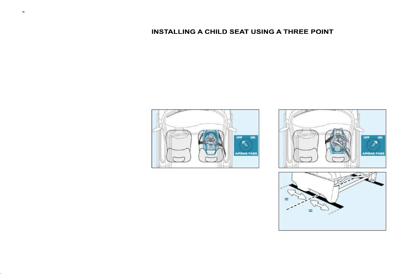
SEAT BELT
"Forwards-facing"
When a "forwards-facing" child seat
is installed on the front passenger
seat , adjust the vehicle's seat to the
intermediate longitudinal position
with the seat back upright and leave
the passenger air bag armed.
* The rules for transporting chil-
dren are specifi c to each country.
Consult the current legislation in
your country.
Intermediate longitudinal
position
"Rearwards-facing"
When a "rearwards-facing" child seat
is installed on the front passenger
seat , it is essential that the passen-
ger air bag * is disarmed. Otherwise,
the child would risk being seri-
ously injured or killed if the air bag
were to infl ate .

47
SEATS
-
CHILD SEATS RECOMMENDED BY CITROËN
CITROËN offers a complete range of recommended child seats which are
secured using a three point seat belt :
Group 0: from birth to 10 kg
Group 0+: from birth to 13 kg
L1
"ROMER Baby-Safe Plus"
Installed in the rear-facing position.
Groups 1, 2 and 3: from 9 to 36 kg
L2
"KIDDY Life"
The use of the restraining cushion is
compulsory for transporting young
children (from 9 to 18 kg).
Groups 2 and 3: from 15 to 36 kg
L3
"RECARO Start''.
L4
"KLIPPAN Optima"
From the age
of 6 years
(approximately 22 kg),
the booster is used on
its own.
Passenger airbag OFF

SEATS
48
-
INSTALLING CHILD SEATS SECURED USING THE SEAT BELT
In accordance with European regulations, this table indicates the options for the installation of child seats secured using the
seat belt and universally approved (a), in accordance with the weight of the child and the seat in the vehicle:
Weight of the child and indicative age
Seat
Below 13 kg
(groups 0 (b) and 0+)
Up to 1 year approx
From 9 to 18 kg
(group 1)
From 1 to 3 years approx
From 15 to 25 kg
(group 2)
From 3 to 6 years approx
From 22 to 36 kg
(group 3)
From 6 to 10 years approx
Front passenger (c) U U U U
Row 2
Side U U U U
Centre U U U U
Row 2 *
Right U U U U
Left U U U U
Row 3 *
Side U U U U
Centre U U U U

49
SEATS
-
"ISOFIX" MOUNTINGS
These are two rings located between
the seat back and the seat cushion.
This ISOFIX mounting system gua-
rantees reliable, safe and fast fi tting
of the child seat in your vehicle.
The ISOFIX child seats are fi tted
with two locks which are secured
easily on these rings.
Your vehicle has been approved in ac-
cordance with the ISOFIX regulation .
The seats, represented below, are fi t-
ted * with regulation ISOFIX mountings:
(a) Universal child seat: child seat
which can be installed in all ve-
hicles using the seat belt.
(b) Group 0: from birth to 10 kg.
(c) Consult the legislation in force
in your country before installing
your child on this seat.
U Seat suitable for the installation of
a child seat secured using a seat
belt and universally approved,
"rear facing" and/or "forward
facing".
* Ludospace 7 seat version: mountings
not available.

50
-
ISOFIX CHILD SEAT RECOMMENDED BY CITROËN AND APPROVED FOR YOUR VEHICLE
Isofi x KIDDY
Group 0+: from birth to 13 kg Group 1: from 9 to 18 kg
Installed in the rear facing position,
on the rear side seat only. Installed in the forwards facing position.
The body of this child seat must be in contact
with the back of the vehicle's front seat.
It is imperative that the vehicle's front seat is adjusted
to the intermediate longitudinal position.
This child seat can also be used on
seats which are not fi tted with ISOFIX
mountings.
In this case, it is compulsory to secure
the child seat to the vehicle's seat
using the three-point seat belt.
Follow the instructions for fi tting
the child seat indicated in the seat
manufacturer's installation guide.

51
SEATS
-
ADVICE ON CHILD
SEATS
The incorrect installation of a
child seat in a vehicle com-
promises the child's protection in the
event of an accident.
Remember to fasten the seat belts or
the child seat harnesses keeping the
slack in relation to the child's body to
a minimum, even for short journeys.
For optimum installation of the "for-
ward facing" child seat, ensure that
the back of the child seat is in contact
with the back of the vehicle's seat
and that the head restraint does not
cause any discomfort.
If the head restraint has to be re-
moved, ensure that it is stored or
attached securely to prevent it from
being thrown around the vehicle in
the event of sharp braking.
Children under the age of 10 must not
travel in the "forward facing" position
on the front passenger seat, unless
the rear seats are already occupied
by other children, cannot be used or
are absent.
Deactivate the passenger airbag
when a "rear facing" child seat is in-
stalled on the front seat. Otherwise,
the child would risk being seriously
injured or killed if the airbag were to
infl ate.
As a safety precaution, do not leave:
- one or more children alone and
unsupervised in a vehicle,
- a child or an animal in a vehicle
which is exposed to the sun, with
the windows closed,
- the keys within reach of children
inside the vehicle.
Installing a booster seat
The chest part of the seat belt must
be positioned on the child's shoulder
without touching the neck.
Ensure that the lap part of the seat
belt passes correctly over the child's
thighs.
CITROËN recommends the use of a
booster seat which has a back, fi tted
with a seat belt guide at shoulder level.
To prevent accidental
opening of the doors, use
the "Child lock".
Take care not to open the
rear windows by more than
one third.
To protect young children from the
rays of the sun, fi t side blinds on the
rear windows.
SEATS
52
-
SEAT BELTS
Locking the seat belts
Pull the strap, then insert the end into
the buckle.
Check that the seat belt is fastened
correctly by pulling the strap.
Unfastening the seat belts
Press the button on the buckle.
Front seat belts
with pre-tensioner
Safety in the event of frontal impacts
has been improved by the introduc-
tion of pre-tensioning seat belts for
the front seats.
Depending on the seriousness of the
impact, the pre-tensioning system
instantly tightens the seat belts and
pulls them against the bodies of the
occupants.
The pre-tensioning seat belts are
armed when the ignition is on.
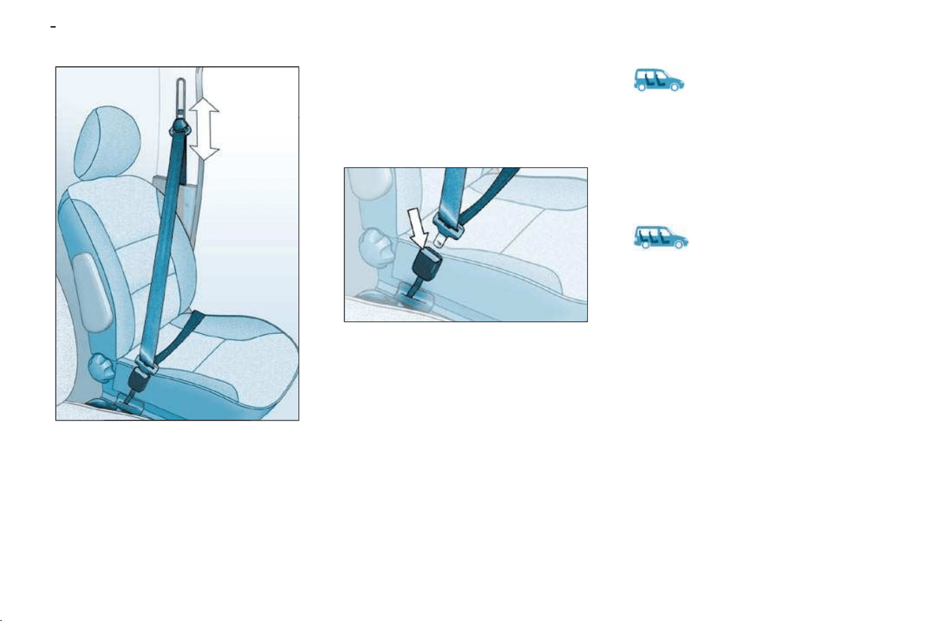
Seat belt height adjustment
To lower or raise: slide the control
downwards or upwards.
Rear seat belts
(5 seat version)
The rear seats are fi tted with three
three-point inertia reel seat belts
(two-part rear seat, 1/3 - 2/3).
Rear seat belts
(7 seat version)
In row 2
The rear seats are fi tted with two
three-point inertia reel seat belts.
In row 3
The rear seats are fi tted with three
three-point inertia reel seat belts.
53
SEATS
-
The driver must ensure that
the passengers use the seat
belts correctly and that they
are all properly restrained
before setting off.
Wherever you are seated in the ve-
hicle, always fasten your seat belt,
even for short journeys.
Do not invert the seat belt buckles as
they will not fulfi l their role fully.
If the seats have armrests * , the lap
part of the seat belt must always
pass under the armrest.
The seat belts are fi tted with an in-
ertia reel permitting automatic adjust-
ment of the length of the strap to your
size. The seat belt is stored automat-
ically when not in use.
Before and after use, ensure that the
seat belt is reeled in correctly.
The lower part of the strap must be
positioned as low as possible on the
pelvis.
The upper part must be positioned in
the hollow of the shoulder.
The inertia reels are fi tted with an au-
tomatic locking device which comes
into operation in the event of a colli-
sion, on emergency braking or if the
vehicle rolls over. You can release
the device by pulling rapidly on the
strap and releasing it.
In order to be effective, a seat belt:
- must be tightened as close to the
body as possible,
- must restrain one adult only,
- must not bear any trace of cuts or
fraying,
- must be pulled in front of you with
a smooth movement, checking
that it does not twist,
- must not be transformed or modifi ed
to avoid altering its performance.
In accordance with current safety
regulations, all repairs and checks
must be carried out by a CITROËN
dealer who guarantees that the work
is carried out correctly.
Have your seat belts checked regu-
larly by a CITROËN dealer and par-
ticularly if the straps show signs of
damage.
Clean the seat belt straps with soapy
water or a textile cleaning product,
sold by CITROËN dealers.
* According to model.
Recommendations for children:
- use a suitable child seat if the pas-
senger is less than 12 years old or
shorter than one metre fi fty,
- do not use the strap-guide * when
a child seat is installed.
- never use the same seat belt to
secure more than one person,
- never allow a child to travel on
your lap.
Depending on the nature and se-
riousness of the impacts , the pre-
tensioning device may be triggered
before and independently of the air
bags. Triggering of the pre-tensioners
is accompanied by a slight emission
of harmless smoke and a noise, due
to the activation of the pyrotechnic
cartridge incorporated in the system.
In all cases, the airbag warning lamp
comes on.
Following an impact, have the seat
belts system checked, and if neces-
sary replaced, by a CITROËN dealer.
After folding or moving a
seat or rear bench seat,
ensure that the seat belt
is positioned and rolled up
correctly.

ACCESS and STARTING
54 -
KEYS
The keys allow you to switch on the
ignition and operate the passenger
air bag disarming switch as well as to
independently operate the locks on
the doors and the fuel fi ller cap.
Locating your vehicle
To locate your vehicle, if you have
locked it, in a car park:
press button A , the courtesy lamps
come on and the direction indica-
tors fl ash for a few seconds.
Changing the battery of the
remote control
CR 2016/3 volt battery.
The information "battery fl at" is given
by an audible signal accompanied
by the message "Remote control
battery fl at" on the screen.
To change the battery, unclip the
casing using a coin at the ring.
If the remote control does not work
after the battery has been changed,
re-programme the remote control.
Reinitialising the remote
control
Switch off the ignition.
Switch the ignition on again.
Press button A immediately for a
few seconds.
Switch off the ignition and remove
the remote control key from the
ignition lock. The remote control
is now working again.
Remote control
Central locking
From the front doors, the keys allow
you to lock and unlock the doors and
tailgate.
If one of the doors or the tailgate is
open, the central locking does not
work.
The remote control performs the
same functions at a distance.
Locking
Press button A to lock the vehicle.
This is confi rmed by fi xed lighting of
the direction indicators for approxi-
mately two seconds.
Unlocking
Press button B to unlock the vehicle.
This is confi rmed by rapid fl ashing of
the direction indicators.
Note : if the vehicle is locked and
unlocking is activated inadvertently,
unless the doors are opened within
30 seconds, the vehicle will lock au-
tomatically.

55
ACCESS and STARTING
-
ELECTRONIC ENGINE
IMMOBILISER
This locks the engine control sys-
tem as soon as the ignition has been
switched off and therefore prevents
starting of the vehicle by anyone who
does not have the key.
The ignition key has an electronic
chip which has a special code. When
the ignition is switched on, the code
must be recognised for the vehicle to
start.
If the system does not function
correctly, the central locking button
indicator light, situated in the centre
of the fascia, fl ashes rapidly when the
ignition is switched on (2nd notch),
accompanied by an audible signal
and a message on the display.
In this case your vehicle will not
start.
Contact a CITROËN dealer as soon
as possible.
Key in ignition
A buzzer sounds on opening the
driver's door, if the key has been left
in the ignition.
Make a careful note of the
number of each key. This
number is coded on the label
attached to the key.
The high frequency remote control is
a sensitive system; do not operate it
while it is in your pocket as there is a
possibility that it may unlock the vehi-
cle, without you being aware of it.
The remote control does not operate
when the key is in the ignition, even
when the ignition is switched off,
except for reprogramming.
Driving with the doors locked may
make access to the passenger com-
partment by the emergency services
more diffi cult in an emergency.
As a safety precaution (with children
on board), remove the key from the
ignition when you leave the vehicle,
even for a short time.
Do not repeatedly press the buttons
of your remote control out of range of
your vehicle.
You run the risk of stopping it from
working and the remote control would
have to be reprogrammed.
When purchasing a second-hand ve-
hicle, have the key codes memorised
by a CITROËN dealer, to ensure that
the keys in your possession are the
only ones which can start the vehicle.
Do not make any modifi cations to the
electronic engine immobiliser system.
If the keys are lost
Visit a CITROËN dealer with the vehi-
cle's V5 registration certifi cate and your
personal identifi cation documents.
The CITROËN network will be able to
retrieve the key code and the trans-
ponder code to order a replacement
key.
A heavy object (key fob...), attached
to the key and weighing down on
its shaft in the ignition switch, could
cause a malfunction.

ACCESS and STARTING
56 -
* According to country.
THE ALARM SYSTEM *
The alarm offers two types of protection:
- exterior protection: the alarm
sounds if a door, the boot or the
bonnet is opened ;
- interior protection: the alarm
sounds if there is a variation in
the volume inside the vehicle
(breaking of a window or move-
ment inside the vehicle) .
Setting the alarm
Switch the ignition off and get out of
the vehicle.
Activate the alarm within fi ve minutes
following your exit from the vehicle,
by locking using the remote control
key (the red indicator light on the
switch 1 , which can be seen from the
outside, fl ashes once a second).
Warning
If, on setting the alarm, a door, the
boot or the bonnet are not closed
correctly, the siren sounds for a mo-
ment.
Close the vehicle correctly to set the
alarm.
If the interior protection alarm is trig-
gered ten times in succession, it is
disarmed automatically. It must be
set again in order for it to operate
correctly.
When the alarm is triggered, the siren
sounds and the direction indicators
fl ash for thirty seconds.
After it has been triggered, the alarm
becomes operational again.
Note: if you wish to lock your vehicle
without setting the alarm, lock it using
the key in the door lock.
Disarming the alarm
Unlock the vehicle using the remote
control key (the red indicator light on
the switch 1 goes out).
Note: if the warning light fl ashes, it is
a sign that the alarm has been trig-
gered in your absence.
To stop it, switch on the ignition.
Note: when the alarm is set, but the
remote control no longer works:
unlock the doors using the key
and open the door; the alarm is
triggered;
switch the ignition on within ten
seconds; the alarm is disarmed.
To set the alarm with exterior
protection only
If, while you are away from the vehicle,
you wish to leave a window partially
open or a pet inside the vehicle, you
need to select exterior protection only:
Switch off the ignition.
Press the button 2 until the light 1
comes on continuously.
Get out of the vehicle.
Press the locking button of the
remote control.
The doors lock.
The red light on the switch fl ashes
once a second.
Malfunction
When the ignition is switched on,
fi xed lighting of the red indicator light,
located in the centre of the fascia, in-
dicates a siren connection fault.
Contact a CITROËN dealer to have
the system checked.
Do not make any modifi ca-
tions to the alarm system, this
could cause malfunctions.

57
ACCESS and STARTING
-
FRONT DOORS AND SLIDING
SIDE DOORS
Front doors
Side doors
Front doors
The driver's door opening control
permits complete unlocking of the
vehicle.
Side doors
Opening the doors from inside
Opening the doors from outside
Sliding side doors
If the fuel tank cap is removed,
the right-hand side door can-
not be opened.
Locking Unlocking from the inside
Front doors
To lock, lower button A .
The closing control of one of the front
doors permits complete locking of
the vehicle.
To unlock and open, lift button A and
pull the handle towards you.
The driver's door opening control
permits complete unlocking of the
vehicle.
From the inside, the sliding
side door is opened and
closed using the handle.
A point of resistance at the
end of the opening travel
secures the door in the
open position.
The side door opening/closing
control only controls the door
concerned.
To close, push the control B forwards
and slide the door.
To open, pull the control B rearwards
and slide the door.

ACCESS and STARTING
58 -
Locking from the inside
Lower or raise control C to lock or unlock
from the inside.
Locking from the inside
Pressing control D operates the
central locking, when the doors are
closed.
Automatic central locking
Your vehicle can lock automatically
while driving (speed greater than
6mph (10 km/h)). You can activate or
deactivate this function.
Unlocking from the inside
Press control D .
It is still possible to open the doors
from the inside.
Activation
Press and hold control D .
Activation of the function is accom-
panied by an audible signal and a
message on the display.
Deactivation
Press and hold control D .
Deactivation of the function is accom-
panied by an audible signal.
Notes:
- doors locked and ignition off: the
indicator light fl ashes,
- doors locked and ignition on: the
indicator light remains on.
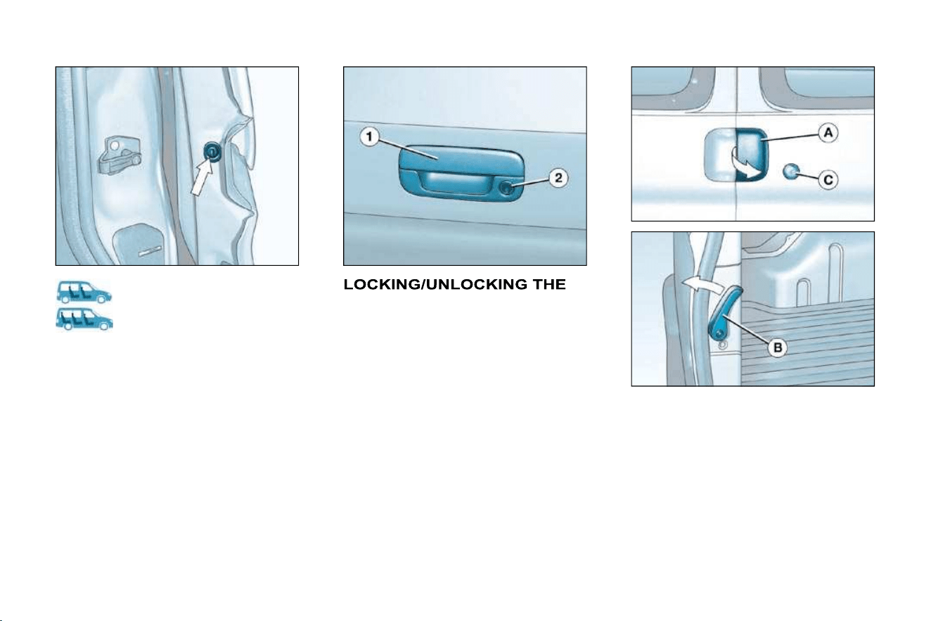
59
ACCESS and STARTING
-
REAR DOORS
Side door child lock
Opening the doors from outside
To open, pull the rear right door han-
dle A towards you and open the rear
left door by pulling the lever B on the
inside.
You can unlock the rear doors by
inserting the key in the lock C .
This prevents opening of the side
door from the inside.
Turn the control a quarter turn using
the ignition key.
TAILGATE
To open the tailgate, operate the
handle 1 and lift it.
You can unlock the tailgate by inserting
the key in the lock 2 .

ACCESS and STARTING
60 -
Opening the doors from inside
The rear door opening controls only
unlock these doors.
To open, lift lever D .
To open the other door, push lever B .
Note: when closing from the inside,
close the right-hand door fi rst ensuring
that lever B is in the vertical position
then close the left-hand door.
Opening the rear doors to 180°
To open the rear doors to 180°,
release the check strap E towards
you when the door is partially open.
When closing the door, the check
strap hooks itself in place again auto-
matically.
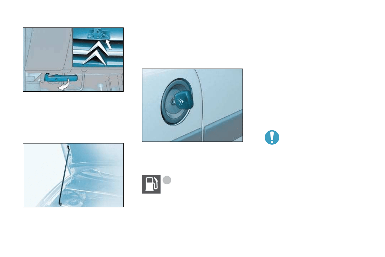
61
ACCESS and STARTING
-
OPENING THE BONNET
Inside the vehicle: pull the handle on
the left-hand side, under the fascia.
Outside the vehicle: lift the catch
and raise the bonnet.
BONNET STRUT
Secure the strut to hold the bonnet
open.
Before closing the bonnet, replace
the strut in its housing.
FILLING WITH FUEL
When the minimum
fuel level in the tank is
reached, this warning
light comes on.
When the cap is removed,
the right-hand sliding side
door cannot be opened.
The key cannot be removed
from the lock until the cap
has been replaced on the
fuel tank.
A label reminds you which type of
fuel to use.
When you fi ll your tank, do not con-
tinue after the third cut-off of the
pump. This could cause your vehicle
to malfunction.
To close
Lower the bonnet and release it at
the end of its travel.
Check that the bonnet is locked.
Low fuel level
You have enough fuel remaining
to drive for approximately 30 miles
(50 km).
The engine must be switched off
when fi lling with fuel.
Insert the key then turn it to the left.
Remove the cap.
The capacity of the tank is approxi-
mately 55 litres for petrol engines
and 60 litres for Diesel engines.
After fi lling the tank, lock the cap.
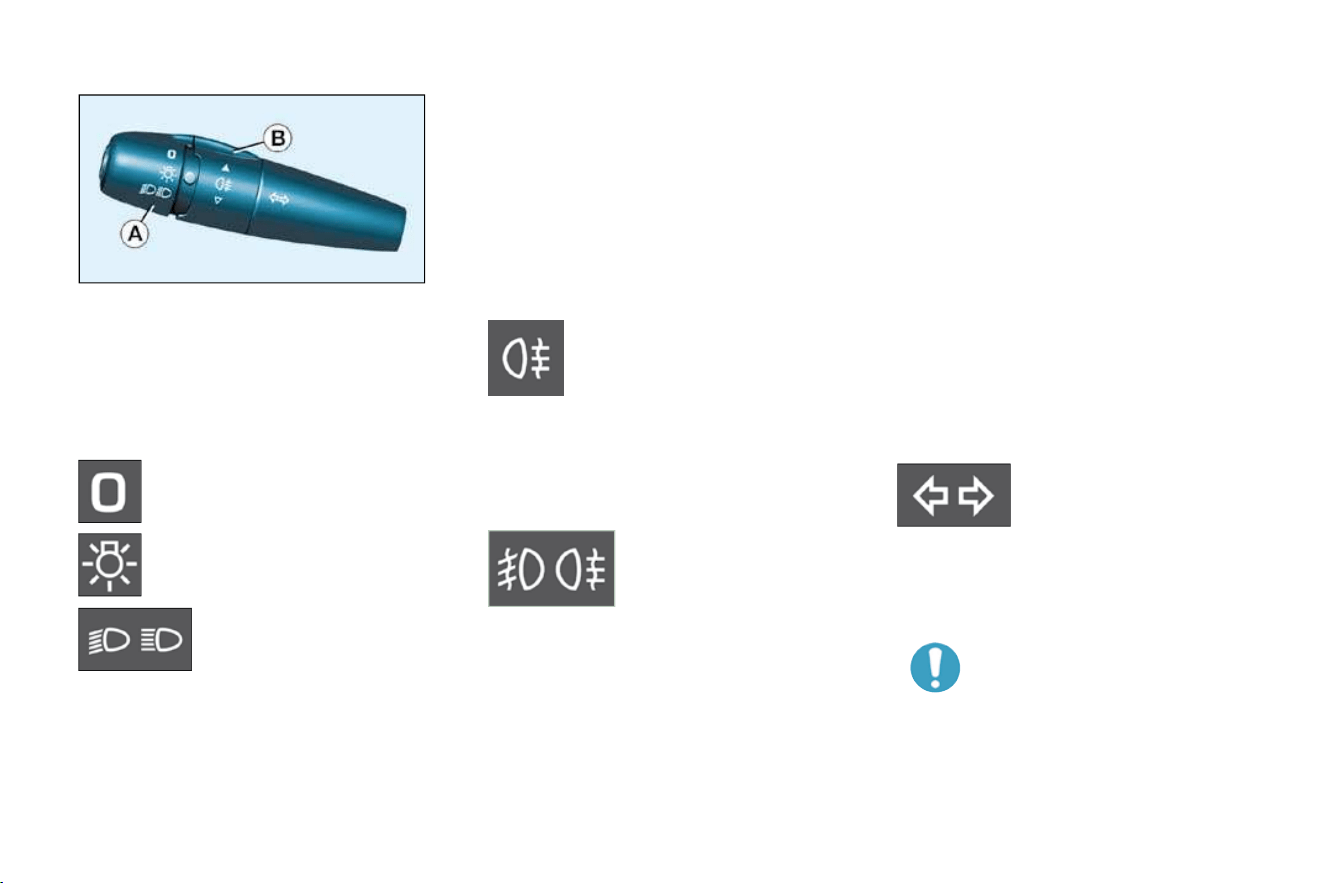
VISIBILITY
62 -
Dipped/Main beam change
Pull the stalk towards you.
Note: with the ignition off, when the
driver's door is opened, a buzzer
sounds if you have left your lights on.
LIGHTS STALK
Lights off
Side lights
Dipped/Main beam
headlamps
Front fog lamps and rear fog
lamp
Rotate the ring forwards to switch on
and backwards to switch off. The sta-
tus is confi rmed by the indicator light
on the instrument panel.
"Follow-me-home" lighting
In poor light, or at night, if you leave
your vehicle, the side lights and
dipped headlamps may remain on for
approximately one minute.
To activate this function:
- place the key in the STOP position,
- place the lights stalk in position 0 ,
- fl ash the headlamps,
- exit the vehicle and lock it.
In good or rainy weather,
both day and night, the front
fog lamps and the rear fog
lamp are dazzling and are
prohibited.
Do not forget to switch them off when
they are no longer needed.
Left: downwards.
Right: upwards.
Direction indicators (fl ashers)
Vehicles fi tted with a rear
fog lamp only (ring B)
Vehicles fi tted with
front fog lamps and
a rear fog lamp
(ring B)
Front fog lamps (fi rst rotation of the
ring forwards).
Front and rear fog lamps (2nd rotation
of the ring forwards).
Note: to switch off the rear fog lamp
and the front fog lamps, turn the ring
backwards twice in succession.
Front and rear lights
Selection is by turning ring A.
Rotate the ring forwards.
This only operates with the dipped/
main beam headlamps.

63
VISIBILITY
-
Windscreen wipers
2 Fast wipe
(heavy rain).
1 Normal wipe
(moderate rain).
I Intermittent wipe.
0 Off.
Single wipe
(press downwards).
WINDSCREEN WIPER STALK
Windscreen and headlamp wash
(according to country)
Pull the windscreen wiper stalk to-
wards you. The windscreen wash
then the windscreen wipers operate
for a fi xed period.
The headlamp wash is also activated,
if the headlamps are on.
Rear windscreen wiper
Turn ring A to the fi rst notch.
The wiping speed is inverse-
ly proportional to the speed
of the vehicle.
In winter, in the event of a
considerable amount of snow
or ice, switch on the rear win-
dow demister. Once deicing
is complete, remove the snow
or ice which has accumulated on the
rear wiper blade. You can now ope-
rate the rear windscreen wiper.
Rear windscreen wash
Turn ring A past the fi rst
notch: the windscreen wash
then the windscreen wiper
operate for a fi xed time.
Operation
In position 1 or 2 , when the vehicle
stops, the windscreen wiper changes
to a lower wiping speed, then resumes
its initial speed when the vehicle starts
again.
In the I ntermittent position, the wiping
speed is proportional to the speed of
the vehicle.
Automatic rear windscreen
wiping
place the front wipers stalk in a
position other than 0 ,
engage reverse gear,
the rear wiper operates with inter-
mittent wiping.
Note : if a bicycle carrier is used, con-
tact a CITROËN dealer to have this
function disarmed.

VISIBILITY
64 -
ELECTRIC WINDOWS
Always remove the ignition
key when leaving the vehicle,
even for a short time.
If an obstacle is encountered
while the electric windows
are in use, you must reverse the
movement of the window. To do this,
press the switch concerned.
When the driver operates the pas-
senger electric window switches, he
must ensure that no one is prevent-
ing correct closing of the windows.
The driver must ensure that passengers
use the electric windows correctly.
Be aware of children when operating
the windows.
1. Driver's electric window
switch
2. Passenger electric window
switch
You have two options:
- Manual operation:
Press switch 1 . The window
stops as soon as the switch is re-
leased.
- Automatic operation (driver):
Press and hold switch 1 . One
touch completely opens or closes
the window.
Automatic closing only operates
when the engine is running.
To partially open the rear windows,
tilt the lever and push it fully to lock
the windows in the open position.

65
VISIBILITY
-
THE EXTERIOR MIRRORS
Passenger side exterior
mirror electric control
From the driver's seat, move the con-
trol 1 in all four directions to adjust.
THE MANUAL INTERIOR
MIRROR
Manual mirrors
Move the lever in all four directions
to adjust.
When the vehicle is parked, the ex-
terior mirrors can be folded back
manually.
The interior mirror has two positions:
- day (normal),
- night (anti-dazzle).
To change from one to the other,
push or pull the lever on the lower
edge of the mirror.

LIFE ON BOARD
66 -

67
LIFE ON BOARD
-
FRONT LAYOUT
4. Courtesy lights
5. Sun visors
Permanently off.
On entering the vehicle:
- they come on when the
vehicle is unlocked or
when a door is opened,
- they switch off after approxi-
mately 30 seconds with the doors
closed, or when the ignition is
switched on.
On leaving the vehicle:
- they come on when the key is re-
moved from the ignition (timing
of approximately 30 seconds) or
when a door is opened,
-
they switch off after approximately
30 seconds with all of the doors
closed, or immediately when the
vehicle is locked.
In this position, the courtesy light may
fl ash while driving if a door is not closed
correctly.
If a door is open, it will switch off auto-
matically after approximately 10 minutes
or when the ignition is switched on.
Permanently on when the
key is in the accessories po-
sition or the ignition is on.
1. Storage in the doors
A. Bottle holder.
B. Can holder.
C. Storage compartment.
2. Overhead storage
Maximum load: 5 kg .
3. Map reading lights
Turn the dial to the right or to the left
to switch them on.
Place the dial in the centre to switch
them off.
6. Glove box
7. Lighter
It permits the connection of a telephone
charger, a baby's bottle warmer, ...
8. Removable ashtray
Pull the cover to open the ashtray.
To empty, after opening, remove it by
pulling upwards.
9. Storage drawer (passenger)
To open the drawer, lift it slightly and
pull it forwards.
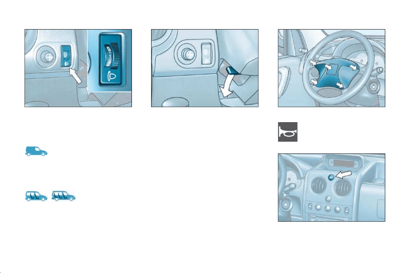
LIFE ON BOARD
68 -
STEERING WHEEL HEIGHT
ADJUSTMENT
HEADLAMP ADJUSTMENT
HORN
HAZARD WARNING LIGHTS
Press the button, the direction indicators
fl ash.
They can operate with the ignition off.
Press one of the spokes or
the centre of the steering
wheel.
0 - With no load.
1 - With partial load.
2 - With average load.
3 - With maximum authorised load.
0 - 1 or 2 people in the front seats.
- - 3 people.
1 - 5 to 7 people.
2 - 5 to 7 people + maximum autho-
rised load.
3 - Driver + maximum authorised load.
Initial setting is position 0.
Depending on the load in your vehicle,
it is recommended that the headlamp
beam is adjusted.
When stationary, lower the handle to
unlock the steering wheel.
Adjust to the desired height and
lift the handle to lock the steering
wheel.

69
LIFE ON BOARD
-
LASHING RINGS
It is recommended that the
load is immobilised by secur-
ing it fi rmly using the lashing
rings on the fl oor.
Use the 6 lashing rings on the lug-
gage compartment fl oor to secure
your loads.
You can use suitable load retainers
(half-height partitions, grille, etc.)
supplied by the CITROËN network.

LIFE ON BOARD
70 -
REAR LAYOUT

71
LIFE ON BOARD
-
1. Load-space cover
To install it:
- position the front ends of the load
space cover on its support and
press gently to put it in place,
- unfold the load space cover fully,
- position the rear ends of the load
space cover on its support and
press gently to put it in place.
To remove it:
- unclip the rear ends,
- fold the load space cover fully,
- unclip the front ends and remove
the load space cover.
To store it, fold it like an accordion.
Do not roll it .
2. High load retaining net
The high load retaining net can be fi tted
behind the front or rear seats.
Open the covers A of the correspond-
ing upper fastenings.
Fit the ends of the metal bar in these
fastenings.
Secure the two net strap hooks be-
hind the front seats, with the rear
seat folded, or in the stowing rings B
on the fl oor.
The rings are located directly below
the corresponding upper fastenings.
Pull the two straps C taut.
3. Stowing rings
4. Side door storage
compartments
5. Trays between the front and
rear seats
6. Seat back storage pockets
7. Cup holder

DRIVING
72 -
HANDBRAKE
Illumination of this warning
light and of the STOP warn-
ing light, accompanied by
an audible signal (while the
vehicle is moving), indicates that the
handbrake is still applied or has not
been released fully.
ANTI-LOCK BRAKING
SYSTEM (ABS) AND THE
ELECTRONIC BRAKE FORCE
DISTRIBUTION (EBFD)
The ABS, in conjunction with the
electronic brake force distribution,
increases the stability and manoeu-
vrability of your vehicle on braking,
in particular on poor or slippery road
surfaces.
Note: when changing wheels (tyres
and rims), make sure that these are
approved.
The anti-lock braking system comes
into operation automatically when
there is a risk of wheel lock.
When this warning light comes
on, connected to the STOP
and ABS warning lights, it
indicates that there is a mal-
function of the electronic brake force
distribution, which can cause a loss of
control of the vehicle when braking.
Stop immediately.
In both cases, consult a CITROËN
dealer.
When this warning light
comes on, accompanied by a
buzzer, it indicates that there
is a malfunction of the ABS,
which can cause a loss of control of
the vehicle when braking.
Normal operation of the ABS may
make itself felt by slight vibrations
of the brake pedal.
In emergency braking, press
very fi rmly without releasing the
pressure.
Releasing
Pull the handle and press the button
to release the handbrake.
Applying
When parking, pull the handbrake to
immobilise your vehicle.

73
-
SPEED LIMITER *
The status of the function is displayed
on the instrument panel in accord-
ance with the following sequences:
Function selected,
displaying of the "Speed
Limiter" symbol.
Function deactivated,
last programmed speed - OFF
(example at 66 mph
(107 km/h)).
Function activated
(example at 66 mph (107 km/h)).
Vehicle speed above
66 mph (107 km/h),
the programmed speed is
displayed fl ashing.
Operating fault detected,
OFF - the dashes fl ash.
Selecting the function
Place the dial in the LIMIT position.
The limiter is selected but is not yet
active. The display indicates dash-
es or the last programmed speed.
Programming a speed
A speed can be programmed without
activating the limiter but with the en-
gine running.
A brief or extended press of the
SET - button decreases the
speed.
A brief or extended press of
the SET + button increases the
speed.
Activation/deactivation (off)
When you have programmed your
speed, pressing this button once acti-
vates the limiter and the programmed
speed is displayed, pressing the but-
ton again deactivates it (OFF).
The operating actions must be carried
out when stationary, with the engine
running, or with the vehicle moving.
* According to version.
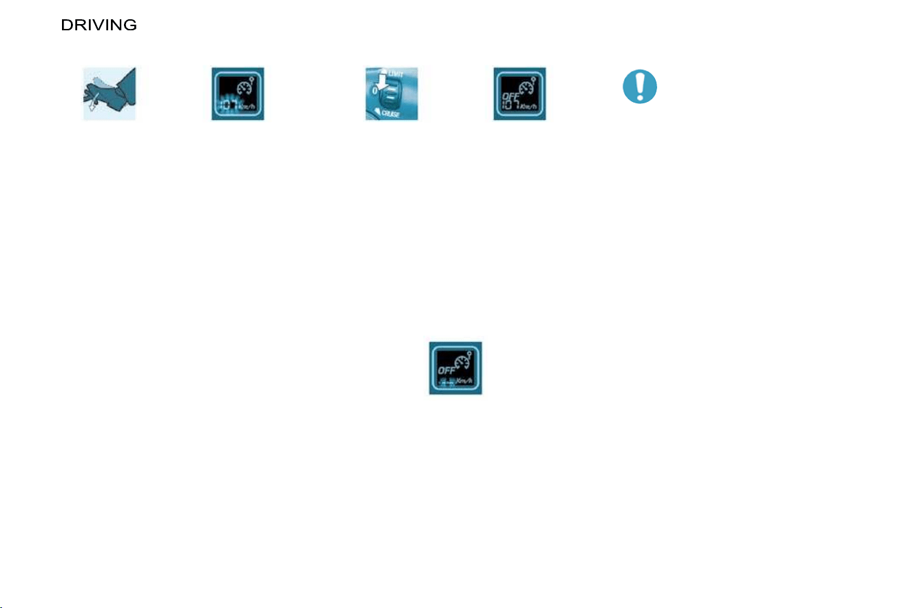
74 -
Exceeding the programmed
speed
Pressing the accelerator pedal in or-
der to exceed the programmed speed
will have no effect unless you press
the pedal fi rmly beyond the point of
resistance .
The limiter is deactivated temporarily
and the programmed speed which is
still displayed fl ashes.
Flashing of the speed
The speed fl ashes:
- following forcing of the accelerator
point of resistance,
- when the limiter cannot prevent
an increase in the vehicle speed
due to the profi le of the road or on
a steep descent,
- in the event of sharp acceleration.
In any event, the speed lim-
iter cannot replace the need
to observe speed limits, nor
can it replace the need for
vigilance and responsibility
on the part of the driver.
The driver must always pay attention
to the profi le of the road, take care
on sharp acceleration and remain in
perfect control of his vehicle.
To prevent the mat from becoming
trapped under the pedals:
- ensure that the mat and its fi xings
are positioned correctly,
-
never fi t one mat on top of another.
Switching the function off
Place dial in position 0 or switch
off the ignition to switch the sys-
tem off. The last programmed
speed remains in the memory.
Operating fault
In the event of a limiter malfunction,
a message is displayed on the multi-
function display accompanied by an
audible signal.
The programmed speed is cleared and
the dashes fl ash for a few seconds.
Contact a CITROËN dealer to have
the system checked.
To return to the limiter function, re-
duce your speed to the programmed
speed or below.

75
-
CRUISE CONTROL *
The status of the function is displayed
on the instrument panel in accord-
ance with the following sequences:
Function selected,
displaying of the "Cruise
Control" symbol.
Function deactivated,
OFF (example at 66 mph
(107 km/h)).
Function activated
(example at 66 mph (107 km/h)).
Vehicle speed above
(e.g. 73 mph (118 km/h)),
the programmed speed is
displayed fl ashing.
Operating fault detected,
OFF - the dashes fl ash.
Selecting the function
Place the switch in the CRUISE
position. The cruise control is se-
lected but is not yet active and no
speed has been programmed.
First activation/programming a
speed
Reach the chosen speed by
pressing the accelerator.
Press the SET - or SET + button.
This programmes the reference
speed and the vehicle will maintain
this speed.
Temporary exceeding of the
speed
It is possible to accelerate and drive
momentarily at a speed greater than
the programmed speed. The value
programmed fl ashes.
When the accelerator pedal is re-
leased, the vehicle will return to the
programmed speed.
The cruise control has a display on
the instrument panel to indicate the
programmed reference speed.
The cruise control maintains a con-
stant vehicle speed programmed by
the driver.
In order for it to be programmed or
activated, the vehicle speed must be
greater than 25 mph (40 km/h) with
at least fourth gear engaged.
If the vehicle is fi tted with a speed lim-
iter and cruise control, these functions
cannot be activated at the same time.
* According to version.
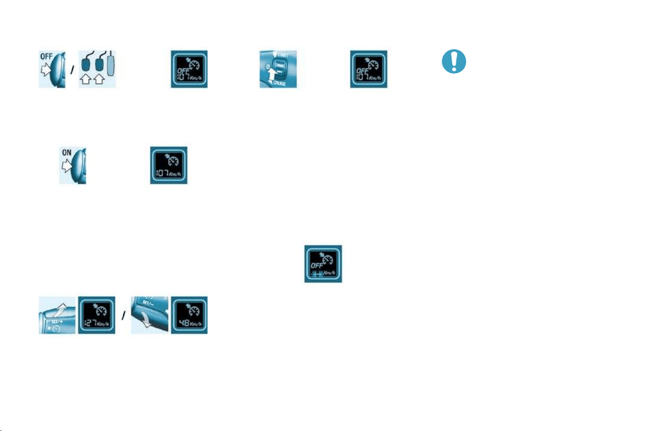
DRIVING
76 -
When changing the pro-
grammed reference speed
by means of a maintained
press, pay attention as the
speed can increase or de-
crease rapidly.
Do not use the cruise control on slip-
pery roads or in heavy traffi c.
In the event of a steep slope, the
cruise control cannot prevent the
vehicle from exceeding the pro-
grammed speed.
In any event, the cruise control can-
not replace the need to observe the
speed limits, nor can it replace the
need for vigilance and responsibility
on the part of the driver.
It is advisable to leave your feet near
the pedals.
To prevent the mat from becoming
trapped under the pedals:
- ensure that the mat and its fi xings
are positioned correctly,
-
never fi t one mat on top of another.
Deactivation (off)
Press this button or the brake or
clutch pedal.
Changing the programmed
reference speed
When the speed is displayed:
press SET + button to increase it.
press the SET - button to decrease it.
Reactivation
Following deactivation of the
cruise control, press this button.
Your vehicle will return to the last
programmed speed.
Alternatively, you can repeat the "fi rst
activation" procedure.
Switching the function off
Place the dial in position 0 or
switch off the ignition to switch
everything off.
Operating fault
In the event of a cruise control mal-
function, a message is displayed on
the multifunction display accompa-
nied by an audible signal.
The programmed speed is cleared
and the dashes fl ash for a few se-
conds.
Contact a CITROËN dealer to have
the system checked.
Cancelling the programmed
reference speed
When the vehicle becomes station-
ary, after switching off the ignition,
the system no longer memorises a
speed.

77
DRIVING
-
FRONT AIRBAGS
These are folded in the centre of the
steering wheel for the driver and in
the fascia for the front passenger.
They are deployed simultaneously,
except in cases where the passen-
ger air bag is disarmed, in the event
of a serious front impact applied in
the impact zone A in the longitudinal
centreline of the vehicle, on a hori-
zontal plane and from the front of the
vehicle towards the rear. The air bag
infl ates between the front occupant of
the vehicle and the fascia to cushion
his forward movement. The airbags
therefore limit the risk of injury to the
head and chest.
The airbags have been designed to
maximise the safety of the occupants
in the event of serious collisions. They
work in conjunction with the force-lim-
iting seat belts. The electronic detec-
tors register and analyse any abrupt
deceleration of the vehicle in the im-
pact detection zones (see diagram):
if the triggering threshold is reached,
the airbags infl ate instantly and pro-
tect the occupants of the vehicle.
Impact detection zones
A. Front impact zone.
B. Side impact zone.
Immediately after the impact, the
airbags defl ate rapidly so that they
do not hinder the visibility of the oc-
cupants nor their exit if necessary
from the vehicle.
The airbags are not deployed in the
case of minor impacts, rear impacts
or in certain roll-over conditions. The
seat belt is suffi cient to ensure maxi-
mum protection in these situations.
The seriousness of a collision de-
pends on the nature of the obstacle
and the speed of the vehicle at the
moment of the collision.
Airbags only operate when the ig-
nition is switched on.
Note : the gas escaping from
the airbags can be a minor
irritant.
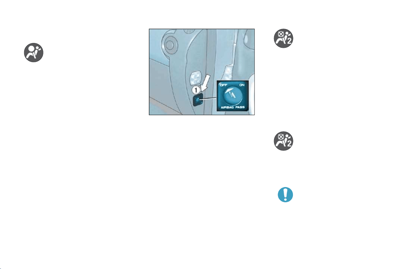
DRIVING
78 -
If this warning light comes on,
accompanied by an audible
signal, contact a CITROËN
dealer to have the system
checked. The airbags may
no longer be triggered in the event of
a serious impact.
Front air bag malfunction
Disarming the passenger air
bag
To ensure the safety of your child,
it is essential to disarm the pas-
senger air bag when you install a
rear-facing child seat on the front
passenger seat. Otherwise, the
child would risk being killed or se-
riously injured if the air bag were
to infl ate.
With the ignition switched off ,
insert the key into the passenger
air bag disarming switch 1 , turn
it to the "OFF" position, then re-
move the key keeping the slot in
this position.
The air bag warning light on
the instrument panel is lit
throughout the period of dis-
arming.
In the "OFF" position, the passen-
ger air bag will not be triggered in the
event of an impact.
As soon as the child seat is removed,
turn the air bag slot to the "ON" po-
sition to re-activate the air bag and
thus ensure the safety of your pas-
senger in the event of an impact.
This is confi rmed by an indi-
cator light, accompanied by
a message on the display.
With the ignition on
(2nd notch), illumination of this warn-
ing light indicates that the passenger
air bag is disarmed (switch in the
"OFF" position).
If the two air bag warning
lights are lit continuously, do
not install a rear-facing child
seat. Consult a CITROËN
dealer.
Disarming check

79
DRIVING
-
SIDE AIRBAGS *
If this warning light comes on,
accompanied by an audible
signal, contact a CITROËN
dealer to have the system
checked. The airbags may
no longer be triggered in the event of
a serious impact.
Airbags malfunction
For the front and side airbags
to be fully effective, observe
the following safety rules:
Wear a correctly adjusted seat
belt.
Sit in a normal upright position.
Do not leave anything between
the occupants and the airbags
(child, animal, object, ...).
This could hamper the operation
of the airbags or injure the occu-
pants.
All work on the air bag systems is
strictly prohibited unless it is car-
ried out by qualifi ed personnel of
the CITROËN network.
After an accident or if the vehi-
cle has been stolen or broken
into, have the air bag systems
checked.
Front airbags
Do not drive holding the steer-
ing wheel by its spokes or resting
your hands on the centre part of
the wheel.
Passengers must not place their
feet on the fascia.
Smoke as little as possible; de-
ployment of the airbags can
cause burns or the risk of injury
from a cigarette or pipe.
Never remove or pierce the steering
wheel or hit it violently.
Side airbags *
Only put approved covers on the
front seats. Consult a CITROËN
dealer.
Do not fi x or glue anything to
the front seat backs. This could
cause injury to the chest or arms
when the side air bag infl ates.
Do not sit with the upper part of
the body any nearer to the door
than necessary.
The side airbags are incorporated
into the front seat backs on the door
side.
The triggering of these airbags re-
quires a serious side impact applied
in the side impact zone B , perpen-
dicular to the longitudinal centreline
of the vehicle, on a horizontal plane
and from the outside of the vehicle
towards the inside. The side air bag
infl ates between the front occupant
of the vehicle and the door trim pad.
It therefore limits the risk of injury to
the chest.
* According to version.

DRIVING
78 -
If this warning light comes on,
accompanied by an audible
signal, contact a CITROËN
dealer to have the system
checked. The airbags may
no longer be triggered in the event of
a serious impact.
Front air bag malfunction
Disarming the passenger air
bag
To ensure the safety of your child,
it is essential to disarm the pas-
senger air bag when you install a
rear-facing child seat on the front
passenger seat. Otherwise, the
child would risk being killed or se-
riously injured if the air bag were
to infl ate.
With the ignition switched off ,
insert the key into the passenger
air bag disarming switch 1 , turn
it to the "OFF" position, then re-
move the key keeping the slot in
this position.
The air bag warning light on
the instrument panel is lit
throughout the period of dis-
arming.
In the "OFF" position, the passen-
ger air bag will not be triggered in the
event of an impact.
As soon as the child seat is removed,
turn the air bag slot to the "ON" po-
sition to re-activate the air bag and
thus ensure the safety of your pas-
senger in the event of an impact.
This is confi rmed by an indi-
cator light, accompanied by
a message on the display.
With the ignition on
(2nd notch), illumination of this warn-
ing light indicates that the passenger
air bag is disarmed (switch in the
"OFF" position).
If the two air bag warning
lights are lit continuously, do
not install a rear-facing child
seat. Consult a CITROËN
dealer.
Disarming check

79
DRIVING
-
SIDE AIRBAGS *
If this warning light comes on,
accompanied by an audible
signal, contact a CITROËN
dealer to have the system
checked. The airbags may
no longer be triggered in the event of
a serious impact.
Airbags malfunction
For the front and side airbags
to be fully effective, observe
the following safety rules:
Wear a correctly adjusted seat
belt.
Sit in a normal upright position.
Do not leave anything between
the occupants and the airbags
(child, animal, object, ...).
This could hamper the operation
of the airbags or injure the occu-
pants.
All work on the air bag systems is
strictly prohibited unless it is car-
ried out by qualifi ed personnel of
the CITROËN network.
After an accident or if the vehi-
cle has been stolen or broken
into, have the air bag systems
checked.
Front airbags
Do not drive holding the steer-
ing wheel by its spokes or resting
your hands on the centre part of
the wheel.
Passengers must not place their
feet on the fascia.
Smoke as little as possible; de-
ployment of the airbags can
cause burns or the risk of injury
from a cigarette or pipe.
Never remove or pierce the steering
wheel or hit it violently.
Side airbags *
Only put approved covers on the
front seats. Consult a CITROËN
dealer.
Do not fi x or glue anything to
the front seat backs. This could
cause injury to the chest or arms
when the side air bag infl ates.
Do not sit with the upper part of
the body any nearer to the door
than necessary.
The side airbags are incorporated
into the front seat backs on the door
side.
The triggering of these airbags re-
quires a serious side impact applied
in the side impact zone B , perpen-
dicular to the longitudinal centreline
of the vehicle, on a horizontal plane
and from the outside of the vehicle
towards the inside. The side air bag
infl ates between the front occupant
of the vehicle and the door trim pad.
It therefore limits the risk of injury to
the chest.
* According to version.

PRACTICAL INFORMATION
80 -
1. Power steering reservoir
2. Windscreen and headlamp wash
reservoir
3. Coolant reservoir
4. Brake fl uid reservoir
5. Battery
6. Air fi lter
7. Dipstick
8. Engine oil reservoir
1.4 LITRE PETROL ENGINE

81
PRACTICAL INFORMATION
-
1. Power steering reservoir
2. Windscreen and headlamp wash
reservoir
3. Coolant reservoir
4. Brake fl uid reservoir
5. Battery
6. Air fi lter
7. Dipstick
8. Engine oil reservoir
1.6 LITRE PETROL ENGINE
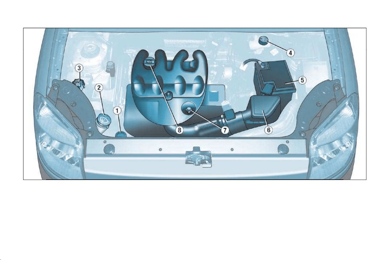
PRACTICAL INFORMATION
82 -
1. Power steering reservoir
2. Windscreen and headlamp wash
reservoir
3. Coolant reservoir
4. Brake fl uid reservoir
5. Battery
6. Air fi lter
7. Dipstick
8. Engine oil reservoir
1.9 LITRE DIESEL ENGINE

83
PRACTICAL INFORMATION
-
1. Power steering reservoir.
2. Windscreen/headlamp wash
reservoir.
3. Coolant reservoir.
4. Brake fl uid reservoir.
5. Battery.
6. Air fi lter.
7. Dipstick.
8. Engine oil reservoir.
9. Priming pump.
1.6 LITRE TURBO DIESEL HDI ENGINE
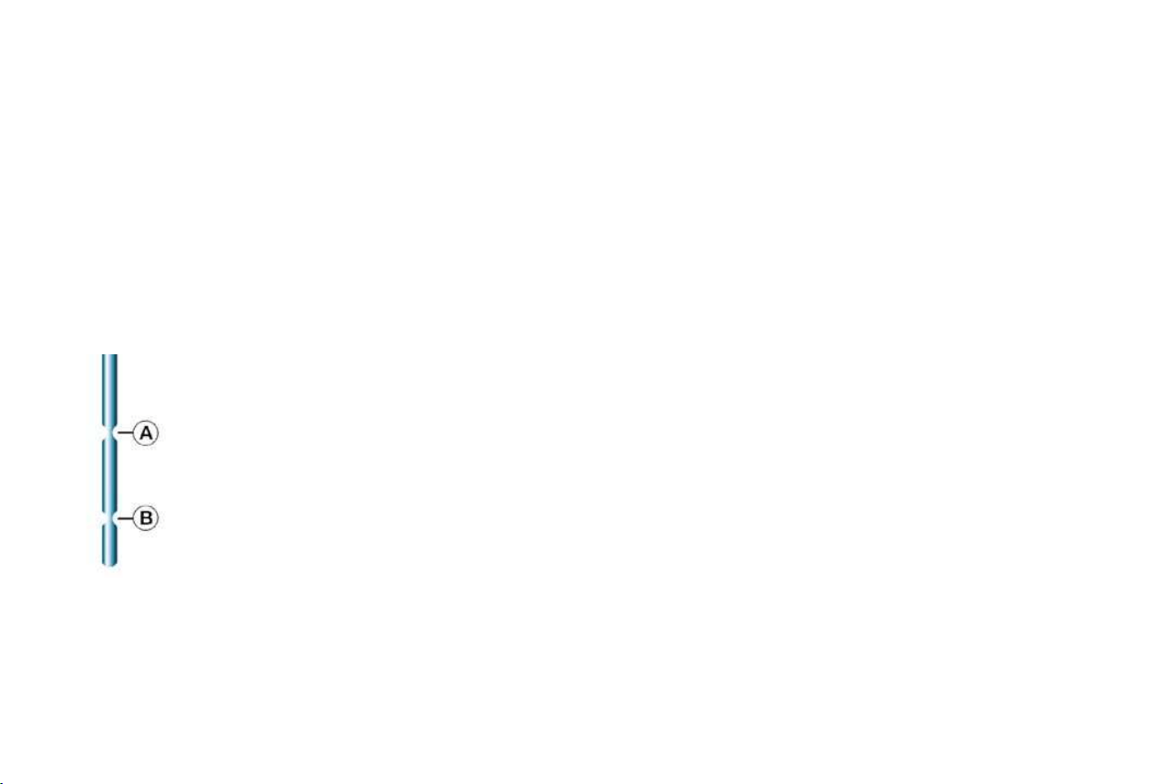
85
PRACTICAL INFORMATION
-
CHECKING THE LEVELS
Dipstick
Oil change
According to the information given in
the servicing booklet.
Note: avoid used oil coming into
prolonged contact with the skin.
Empty the used oil into the contain-
ers intended for this purpose in the
CITROËN network.
Viscosity selection
In all cases, the oil selected must meet
the manufacturer's requirements.
Note: the coolant does not need to
be changed.
For vehicles equipped with a parti-
cle fi lter, the engine fan may operate
after the ignition has been switched
off, even when the engine is cold.
There are two marks
on the dipstick:
A = maximum
Never fi ll past this
mark.
B = minimum
To maintain the reliability
of engines and emission
control systems, the use
of additives in engine oil
is prohibited.
Brake fluid level:
The brake fl uid must be changed
according to the manufacturer's
servicing schedule.
Use fl uids recommended by the
manufacturer, which fulfi l DOT4 stan-
dards.
Note: brake fl uid is harmful to health
and very corrosive. Avoid all contact
with the skin.
Cooling system
Use the fl uid recommended by the
manufacturer.
When the engine is warm, the tem-
perature of the coolant is controlled
by the engine fan. As this fan can op-
erate with the ignition key removed
and because the cooling system is
pressurised, wait for at least one hour
after the engine has stopped before
carrying out any work.
Slacken the cap by two turns to re-
lease the pressure to prevent any
risk of scalding. When the pressure
has dropped, remove the cap and
top up the level.
Used oil
Do not dispose of used oil, brake fl uid or
coolant into drains or onto the ground.
Power steering reservoir
Open the reservoir, with the en-
gine at ambient temperature. The
level should always be above the
MIN. mark and close to the MAX.
mark.
Windscreen and headlamp
wash level
For best quality cleaning and for
your safety, we would advise that
you use products recommended by
CITROËN.
For optimum cleaning and to prevent
freezing, this fl uid must not be topped
up or replaced with water.
Oil level
Check the level regularly and top
up between changes. The maxi-
mum consumption is 0.5 l per
600 miles (1 000 km).
Check the level with the vehicle level,
engine cold, using the oil level gauge
on the instrument panel or the dipstick.

PRACTICAL INFORMATION
86 -
CHECKS
Oil filter
Change the fi lter regularly, in accord-
ance with the servicing schedule.
Only use products recom-
mended by CITROËN or
products of equivalent quality
and specifi cations.
To ensure best performance from
components as important as the
power steering and the braking sys-
tem, CITROËN selects and offers
quite specifi c products.
To prevent damage to the electrical
units, avoid washing the engine.
RUNNING OUT OF FUEL
(DIESEL)
If you should run out of fuel, it is nec-
essary to re-prime the circuit:
- fi ll the fuel tank with at least fi ve litres
of diesel,
- squeeze and release the manual
re-priming pump, under the bonnet
under the protective cover, until fuel
appears in the transparent pipe,
- operate the starter until the engine
starts.
FUEL SUPPLY CUT-OFF
(PETROL)
In a serious collision, a mechanism
prevents fuel from reaching the en-
gine.
To re-establish the fuel supply, press
the switch on the corner of the front
right-hand suspension assembly, under
the bonnet.
Air filter and passenger
compartment filter
Have the fi lter elements replaced regu-
larly. If you drive in dusty conditions,
change them twice as often.
Brake pads
Brake pad wear depends on the style
of driving, in particular for vehicles
which are used in town, over short
distances.
It may be necessary to check the
thickness of the pads, even between
services.
Disc and drum wear status
For any information relating to check-
ing the disc and drum wear status,
contact a CITROËN dealer.
Manual gearbox
This does not require an oil change.
Check the level in accordance with the
manufacturer's servicing schedule.
To check the main levels and cer-
tain components, in accordance
with the manufacturer's servicing
schedule, refer to the pages of
the servicing booklet which corre-
spond to your vehicle's engine.
Handbrake
Where the handbrake travel is too
great or there is a reduction in the
performance of the system, the
handbrake should be adjusted, even
between services.
Have the system checked by a
CITROËN dealer.
Battery
At the start of winter, have your battery
checked by a CITROËN dealer.

87
PRACTICAL INFORMATION
-
CHANGING A WHEEL
Parking the vehicle
- If possible, park the vehicle on
level, stable and non-slippery
ground.
- Apply the handbrake, switch off
the ignition and engage fi rst or
reverse gear.
Removing a wheel
- Chock the rear of the wheel di-
agonally opposite the wheel to be
changed, using the chock 2 .
- Remove the wheel trim using the
wheelbrace 1 , by pulling at the
valve passage hole.
- Slacken the wheel bolts.
- Place the jack under the locat-
ing point on the sub-frame A
that is closest to the wheel to be
changed. Ensure that the entire
surface of the jack base plate is
in contact with the ground.
- Extend the jack, completely un-
screw the bolts and remove the
wheel.
Access to the spare wheel and
the jack
The wheel is located outside the ve-
hicle, under the rear fl oor, supported
by a metal carrier.
- Remove the jack and the wheelbrace 1 , secured behind the driver's
seat.
- Remo
ve the jack and the wheelbrace 1 secured in an interior housing
above the rear right wheel.
- Using the wheelbrace 1 , slacken the spare wheel carrier retaining bolt,
located on the inside near the closing system.
- Lift the carrier to release the hook rearwards, then lower it.
- Remove the chock 2 located in the spare wheel.

PRACTICAL INFORMATION
88 -
For your safety, always
change a wheel:
- on level, stable and non
slippery ground,
- with the handbrake applied,
- with fi rst or reverse gear en-
gaged,
- with the vehicle chocked,
- making absolutely sure that the
occupants get out of the vehicle
and wait in a safe location.
Never go underneath the vehicle
when it is raised using the jack only.
The jack and the tool kit are specifi c
to your vehicle. Do not use them for
other purposes.
Refitting the wheel
- After positioning the wheel, lightly
pre-tighten the bolts using the
wheelbrace.
-
Compress the jack and release it.
- Fully tighten the bolts using the
wheelbrace.
- Replace the trim, starting at the
valve passage hole, and press it
on using the palm of the hand.
Replacing the wheel in the
carrier
- Replace the chock 2 in the
wheel.
- Replace the wheel in the carrier.
- Lift the wheel then the carrier and
reposition the hook.
- Do not forget to fully tighten the
spare wheel carrier retaining
bolt.
- Stow the wheelbrace 1 and the
jack.
After changing the wheel
- Have the tightening of the bolts
and the pressure of the spare tyre
checked as soon as possible by a
CITROËN dealer.
- Have the punctured tyre repaired
and replace it on the vehicle as
soon as possible.
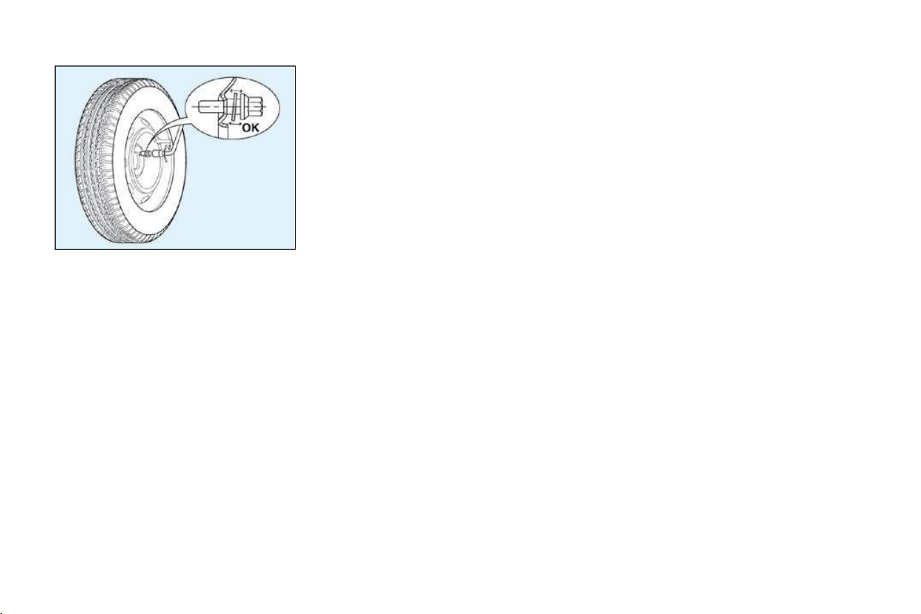
89
PRACTICAL INFORMATION
-
SPECIAL FEATURES
OF ALLOY WHEELS
Fitting the spare wheel
If your vehicle is equipped with a
steel spare wheel, when fi tting it, it is
normal to notice that the bolt wash-
ers do not come into contact with the
rim. The spare wheel is secured by
the cone-shape of each bolt.
Fitting snow tyres
If you fi t snow tyres that are mounted
on steel rims onto your vehicle, it is
essential that you use special bolts
available from your CITROËN dealer.
* According to model and country.
ANTI-THEFT BOLT *
If your wheels are fi tted with an anti-
theft bolt (one per wheel), it must be
unscrewed using an anti-theft socket
(which was given to you on delivery
of your vehicle along with the dupli-
cate keys and the confi dential card)
and the wheelbrace.
Note: make a careful note of the
code number engraved on the top of
the anti-theft socket. This will enable
you to obtain a duplicate anti-theft
socket from your
CITROËN
dealer.

PRACTICAL INFORMATION
90 -
CHANGING A BULB
2. Side lights (W 5 W)
-
Turn and remove the protector A .
- Pull the bulb holder rearwards.
- Change the bulb.
3. Direction indicators
(PY 21 W amber)
- Turn the bulb holder B a quarter
turn and remove it.
- Change the bulb.
Front lights
1. Dipped beam headlamps/Main
beam headlamps (H4-60/55 W)
-
Turn and remove the protector A .
- Disconnect the connector.
- Unclip the spring.
- Remove and replace bulb.
Note : in certain weather conditions
(low temperatures, humidity), the
presence of condensation on the
inside of the glass of the head-
lamps and rear lights is normal ; it
disappears a few minutes after the
lights have been switched on.

91
PRACTICAL INFORMATION
-
Only use H4 bulbs manufac-
tured by:
- GE/TUNGSRAM,
- PHILIPS,
- OSRAM,
to avoid damaging the headlamps.
These meet the anti-UV (ultra-violet)
specifi cations necessary for the cor-
rect operation and reliability of the
headlamps.
The headlamps are fi tted with a poly-
carbonate lens coated with a protec-
tive varnish. You are strongly advised
to avoid cleaning them using a dry or
abrasive cloth and using detergent
products or solvents.
Use a soft, damp cloth.
High pressure washing : when us-
ing this type of washing on stubborn
dirt, do not persist on the headlamps,
the lights and their surround to avoid
damaging their coating and their
seal.
Direction indicator side repeaters
(WY 5 W amber)
-
Push the transparent cover for-
wards or rearwards and release it.
- Turn the bulb holder a quarter
turn.
- Change the bulb.
Amber coloured bulbs (direc-
tion indicators and side re-
peaters) must be replaced by
bulbs of identical specifi ca-
tion and colour.

PRACTICAL INFORMATION
92 -
- Open the rear door.
- Unscrew the nut A .
- Push the light unit gently towards
the interior of the vehicle to unclip
the two side retaining clips.
- Remove the light unit and discon-
nect it.
- Unclip the bulb holder by pressing
the tabs B ,
- Change the faulty bulb.
Number plate lights (W 5 W)
Insert a thin screwdriver into one
of the external holes of the lens.
Push it outwards to unclip it.
Remove the lens.
Change the faulty bulb.
Rear lights
1. Fog lamp (P21 W).
2. Direction indicators (P21 W).
3. Reversing lights (P21 W).
4. Brake lights/Side lights
(P21/5 W).
High pressure washing: when using
this type of washing on stubborn dirt,
do not persist on the headlamps, the
lights and their surround to avoid dam-
aging their coating and their seal.

93
PRACTICAL INFORMATION
-
Third brake light (tailgate)
(W 5 W)
With the tailgate open, unscrew
the two nuts.
Unclip the support to gain access
to the bulbs.
Change the faulty bulb.
Third brake light
(rear left door) (W 5 W)
Remove the housing cover by
pressing the tab A (round sec-
tion) at the end of the light.
Pull the housing cover rearwards.
Squeeze the two tabs B to re-
move the bulb holder.
Pull the faulty bulb and change it.
To refi t, proceed in the reverse order.

PRACTICAL INFORMATION
94 -
Removing and fi tting a fuse
Before changing a fuse, the cause
of the fault must be found and reme-
died. The fuse numbers are indicated
on the fuse box.
Use the pliers B .
CHANGING A FUSE
The fuse boxes are located under
the fascia and in the engine compart-
ment.
Fascia fuse box
Unclip the cover to gain access to the
fuses.
The spare fuses and the pliers B are
secured on the inside of the cover A .
Correct
Incorrect
Pliers B
Always replace a faulty fuse with a fuse
of the same rating (two fuse types ac-
cording to manufacturer - see images).
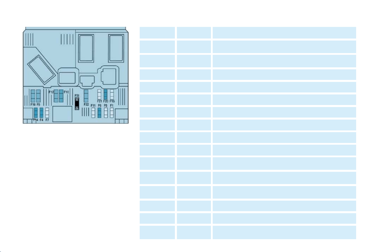
95
PRACTICAL INFORMATION
-
Fuse Rating Functions
1 15A Rear wiper.
4 20A
Multi-function display - Instrument panel - Audio
equipment - Steering wheel controls.
5 - Not used.
6 10A Diagnostic socket.
7 - Not used.
9 30A Heated seats.
10 40A Rear windows and mirrors demisting.
11 15A Rear wiper (tailgate).
12 30A Front electric windows.
14 10A Engine fuse box - Steering wheel controls.
15 15A
Instrument panel - Multi-function display - Audio
equipment.
16 30A
Locking/unlocking controls for doors, bonnet and boot.
20 10A Right-hand brake light.
21 15A Left-hand brake light.
22 20A
Front courtesy light - Map reading light - Lighter -
Electric mirror.

PRACTICAL INFORMATION
96 -
The electrical circuit of your vehicle is designed to operate with standard or optional equipment.
Before installing other electrical equipment or accessories in your vehicle, consult a CITROËN dealer.
Some electrical accessories or the way in which they are fi tted may have an adverse effect on the operation of your
vehicle (its electronic control circuits, the audio circuit and the electrical charging circuit).
CITROËN declines any responsibility for expenses incurred through the repair of your vehicle or for any malfunctions
resulting from the installation of auxiliary accessories, not supplied and not recommended by CITROËN and not installed in
accordance with it's instructions, in particular for any equipment the power consumption of which exceeds 10 milliamps.
The maxi fuses provide additional protection for the electrical systems. Any work on these fuses must be carried out by a
CITROËN dealer.

97
PRACTICAL INFORMATION
-
Fuse N° Rating Functions
1 10A
Pre-heat unit (diesel) - Brake and clutch switches -
Reversing lights.
2 15A Fuel pump.
3 10A ABS control unit.
4 10A Engine control unit.
5 - Not used.
6 15A Front fog lamps.
7 20A Headlamp wash pump.
8 20A Fan assembly relay - Engine control unit.
9 15A Left-hand dipped beam.
10 15A Right-hand dipped beam.
11 10A Left-hand main beam.
12 10A Right-hand main beam.
13 15A Horn.
14 10A Front and rear windscreen wash pumps.
15 30A Oxygen sensor - Air fl ow sensor.
16 30A Air pump relay.
17 30A Front windscreen wiper.
18 40A Air conditioning fan.
Engine compartment fuse box
To gain access to the box in the
engine compartment (next to the
battery), unclip the cover.
After carrying out work, close the
cover very carefully.

PRACTICAL INFORMATION
98 -
ECONOMY MODE FUNCTION
After the engine has stopped, with
the key in the "accessories" position,
certain functions (windscreen wiper,
electric windows, courtesy lights,
audio equipment, etc.) can only be
used for a combined duration of ap-
proximately thirty minutes, to prevent
discharging the battery.
Once the thirty minutes are over, a
switching to economy mode mes-
sage appears on the multi-function
display and the active functions are
put on standby.
These functions are reactivated au-
tomatically next time the vehicle is
driven.
In order to resume the use of these
functions immediately, the engine
must be started and left to run for a
few minutes.
The time available to you will then
be double the duration for which the
engine is left running. However, this
period will always be between fi ve
and thirty minutes.
BATTERY
It is advisable to disconnect the
battery if the vehicle is not to be
used for a period of more than
one month.
Before disconnecting the bat-
tery, you must wait 2 minutes
after switching off the ignition.
Never disconnect a terminal
when the engine is running.
Never charge a battery without fi rst
disconnecting the terminals.
Close the windows and the roof before
disconnecting the battery.
After every reconnection of the bat-
tery, switch on the ignition and wait
1 minute before starting to allow the
electronic systems to be initialised. If
slight diffi culties are experienced af-
ter this, please contact a CITROËN
dealer.
A fl at battery prevents the
engine from starting.
To start the vehicle from
another battery:
- Connect the red cable to the positive
(+) terminals of the two batteries,
- Connect one end of the green or
black cable to the negative (-) ter-
minal of the slave battery,
- Connect the other end of the
green or black cable to an earth
point on the broken down vehi-
cle as far as possible from the
battery (for example, right-hand
engine mounting).
Operate the starter, let the engine run.
Wait for the engine to return to idle,
then disconnect the cables.
To charge the battery using a
battery charger:
- Disconnect the battery,
- Follow the instructions for use
given by the battery charger man-
ufacturer,
- Reconnect starting with the nega-
tive (-) terminal,
- Check that the terminals and
connectors are clean. If they are
covered with sulphate (white or
greenish deposit), disconnect
them and clean them.

99
PRACTICAL INFORMATION
-
Making the connections
A1: -
A2: - Digital control
(manufacturer)
A3: - Digital control
(manufacturer)
A4: - Audio equipment
multiplexing (manufacturer)
A5: -
A6: (+ve) Accessories
A7: (+ve) Permanent
A8: (-ve) Earth
B1: (+)
B2: (-)
B3: (+) Front right speaker and
tweeter
B4: (-) Front right speaker and
tweeter
B5: (+) Front left speaker and
tweeter
B6: (-) Front left speaker and
tweeter
B7: (+)
B8: (-)
FITTING SPEAKERS
The factory-fi tted equipment allows
the fi tting of:
- 35 mm diameter tweeters in the
fascia,
- 165 mm diameter speakers in the
front doors.
FITTING AUDIO EQUIPMENT
Your vehicle is equipped with certain
factory-fi tted audio equipment:
- roof aerial,
- coaxial aerial cable,
- basic interference suppression,
- supply to front speakers and
tweeters,
- two 8-way connectors.
Contact a CITROËN dealer
before fi tting audio equip-
ment or speakers in your
vehicle.

PRACTICAL INFORMATION
100 -
SNOW SCREEN *
The snow screen is installed on the
lower part of the front bumper to pre-
vent the accumulation of snow at the
radiator cooling fan.
Remove the snow screen:
- when the exterior temperature is
higher than 10 °C,
- when towing,
- for speeds higher than 75 mph
(120 km/h).
FITTING
Offer up the snow screen facing
the front bumper.
Put it in place positioning the lower
clips A in the bumper.
Press the snow screen at each
upper clip B .
REMOVAL
Press the two upper clips B and
pull the snow screen.
*
As an accessory or according to country.

101
PRACTICAL INFORMATION
-
Without lifting (four wheels on
the ground)
You must always use a towbar.
By lifting (two wheels only on
the ground)
It is preferable to lift the vehicle by
the wheels.
TOWING YOUR VEHICLE
From the front or the rear
Attach the towbar to the towing eye.
Never use the radiator cross-
member.
When towing another vehicle,
it must freewheel.
Place the gearbox in "neutral".
Failure to observe this instruction
may result in damage to certain brak-
ing components and the absence of
braking assistance when the engine
is started again.

PRACTICAL INFORMATION
102 -
TOWING A TRAILER,
CARAVAN, BOAT, ETC.
We recommend the use of original
CITROËN towbars and their har-
nesses that have been tested and
approved from the design stage of
your vehicle and that the fi tting of the
towbar is entrusted to a CITROËN
dealer.
If the towbar is not fi tted by a
CITROËN dealer, it is imperative that
it is fi tted using the electrical pre-
equipment installed at the rear of the
vehicle, in accordance with the man-
ufacturer's instructions.
Your vehicle is primarily designed
for transporting people and luggage
but it may also be used for towing a
trailer.
Driving with a trailer subjects the tow-
ing vehicle to more signifi cant stress
and its driver must be particularly
careful.
Air density decreases with altitude,
thus reducing engine performance.
Above 1 000 metres, the maximum
towing load must be reduced by 10 %
and so on for every 1 000 metres of
altitude.
Driving advice
Tyres: Check the tyre pressures of
the towing vehicle and of the trailer,
observing the recommended pres-
sures.
Braking: Towing increases the braking
distance.
Lights: Check the electrical signalling
on the trailer.
Side wind: Take into account the
increased sensitivity to side wind.
Cooling: Towing a trailer on a slope
increases the temperature of the
coolant.
As the fan is electrically controlled,
its cooling capacity is not dependent
on the engine speed.
On the contrary, use a high gear to
lower the engine speed and reduce
your speed.
The maximum towing load on a long
slope depends on the gradient and
the outside temperature.
In all cases, pay attention to the coolant
temperature.
In certain cases of particularly ardu-
ous use (towing the maximum load
on a steep gradient in high tempera-
tures), switching off the air condition-
ing permits the recovery of engine
power and therefore an increase in
the towing capacity.
If the warning light comes on, stop
the vehicle and switch off the engine
as soon as possible.
Distribution of loads: Distribute the
load in the trailer so that the heaviest
items are as close as possible to the
axle and the nose weight approach-
es the maximum permitted without
exceeding it.

103
PRACTICAL INFORMATION
-
ACCESSORIES
These accessories and parts, hav-
ing been tested and approved for
reliability and safety, are all adapted
to your vehicle. A wide range of rec-
ommended accessories and original
parts is offered.
The fi tting of electrical equip-
ment or accessories which
are not recommended by
Automobiles CITROËN may
result in the failure of your vehicle's
electronic system. Please note this
specifi c warning. You are advised
to contact a representative of the
Marque to be shown the range of
recommended equipment and ac-
cessories.
Depending on the country in which
the vehicle is sold or operated, it is
compulsory to have a high visibility
safety jacket, warning triangle and
replacement bulbs available in the
vehicle.
Screenwash, interior and exterior
cleaning and maintenance products,
replacement bulbs, ...
Anti-theft alarm, window engraving,
fi rst aid kit, high visibility safety jack-
et, rear parking assistance, warning
triangle, ...
Audio equipment, hands-free kit,
speakers, CD changer, navigation, ...
Regardless of the audio and telemat-
ic equipment offered on the market,
the technical constraints linked with
the fi tting of equipment of these fami-
lies of products mean that the spe-
cial features of the equipment and
its compatibility with the capacities
of the your vehicle's standard equip-
ment must be taken into account.
Please contact a CITROËN dealer
for information before fi tting such
equipment.
Front mud fl aps, rear mud fl aps,
15/17 inch alloy wheels, wheelarch
trim, leather steering wheel, ...
Range of professional equipment
Load retainers (all models).
Loading roller.
Towbar, towbar harness: trailer
towbar which must be fi tted by the
CITROËN network.
Separation partitions and grilles,
smooth, non-slip wooden protective
fl oor.
Protective grilles.
Installation of
radiocommunication transmitters
Before installing accessory radio-
communication transmitters with an
external aerial on your vehicle, you
are advised to contact a representa-
tive of the CITROËN marque.
The CITROËN Network will inform
you of the specifi cations (frequency
band, maximum output power, aerial
position, specifi c installation condi-
tions) of the transmitters which can be
fi tted, in accordance with the Motor
Vehicle Electromagnetic Compatibility
Directive (2004/104/CE).
Range of comfort, leisure and
maintenance equipment
Front seat covers compatible with
air bags, bench, rubber mats, car-
pet mats, snow chains, blind, tailgate
bicycle carrier, roof bars (max load
120 kg), transverse roof bars (max
load 100 kg), ...
To prevent the mat from becoming
caught under the pedals:
- ensure that the mat and its fi xings
are positioned correctly,
-
never fi t one mat on top of another.
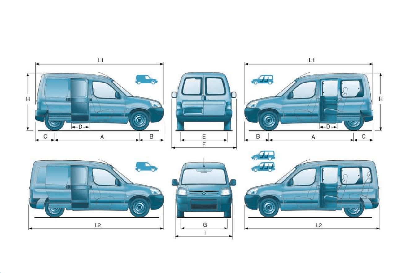
TECHNICAL DATA
104 -
EXTERIOR DIMENSIONS (IN MM)

105
TECHNICAL DATA
-
Light van Ludospace
L1 4 137
L2 4 437
H 1 796 to 1 819 1 810
A 2 693
B 836
C 608
D 570 550
E 1 440 1 440 or 1 452
F 1 960
G 1 420 1 420 or 1 436
I 1 724

TECHNICAL DATA
106 -
INTERIOR DIMENSIONS (IN MM) AND VOLUMES (IN M
3
) LIGHT VAN
L1 L2
J 1 155
K 1 320
M 1 190
N 1 190
O 568
P 1 340 1 640
m
3
3.25 3.6

107-
INTERIOR DIMENSIONS (IN MM) LUDOSPACE
L1 L2
Row
2 bench
seat in
position
- normal 1.25 1.75
- fully folded 2.8 3.25
VOLUMES (IN M
3
)
LUDOSPACE 7 SEAT VERSION
L2
Row 2 and
row 3 bench
seats in
position
- normal 0.2
- fully folded 3
3
)
LUDOSPACE 5 SEAT VERSION

108 -
PETROL ENGINES AND GEARBOXES
Model codes
GA/GB/GC/GD/GF/GG/GJ...
...KFWC
GA/GJ/GK/GN...
...NFUC
ENGINES 1.4 litre 1.6 litre
Cubic capacity (cm
3
) 1 360 1 587
Bore x stroke (mm) 75 x 77 78.5 x 82
EU standard maximum power (kW) 55 80
Maximum power at engine speed (rpm) 5 500 5 800
EU standard maximum torque (Nm) 120 147
Maximum torque at engine speed (rpm) 3 400 4 000
Fuel Ron 95 - Ron 98 Ron 95 - Ron 98
Catalytic converter Yes Yes
Gearbox Manual (5 speed) Manual (5 speed)
Oil capacity (in litres)
Engine (with cartridge replacement) 3 (1) - 3.25 (2) 3.2 (1) - 3.4 (2)
Gearbox - Final drive 2 2
(1) Draining by gravity - (2) Draining by suction

TECHNICAL DATA
110 -
Quality of the fuel used for petrol engines
The petrol engines are perfectly compatible with E5 type petrol biofuels (containing 5 % ethanol), conforming to European
standard EN 228.
E85 type fuels (containing up to 85 % ethanol) are reserved exclusively for vehicles marketed for the use of this type of fuel
(BioFlex vehicles). The quality of the ethanol must comply with European standard EN 15376.
For Brazil only, special vehicles are marketed to run on fuels containing up to 100 % ethanol (type E100).
Quality of the fuel used for Diesel engines
The Diesel engines are perfectly compatible with biofuels which conform to current and future European standards (diesel fuel
which complies with standard EN 590 mixed with a biofuel which complies with standard EN 14214) which can be distributed at
the pumps (possible incorporation of 0 to 7 % Fatty Acid Methyl Ester).
The use of any other type of (bio)fuel (vegetable or animal oils, domestic fuel...) is strictly prohibited (risk of damage to the
engine and fuel circuit).

109
TECHNICAL DATA
-
Model codes
GA/GB/GC/GD/GF/
GG/GJ/GK/GN...
...9HWC
GA/GB/GC/GD/GF/
GG/GJ/GK/GN ...
... 9HXC
GA/GB/GC/GD/GF/
GG/GJ/GK/GN...
... WJYB
ENGINES 1.6 litre Turbo HDI 75 1.6 litre Turbo HDI 92 1.9 litre
Cubic capacity (cm
3
) 1 560 1 560 1 867
Bore x stroke (mm) 75 x 88.3 75 x 88.3 82.2 x 88
EU standard maximum power (kW) 55.2 66.2 51
Maximum power at engine speed (rpm) 4 000 4 000 4 600
EU standard maximum torque (Nm) 175 215 125
Maximum torque at engine speed (rpm) 1 750 1 750 2 500
Fuel Diesel Diesel Diesel
Catalytic converter Yes Yes Yes
Gearbox Manual (5 speed) Manual (5 speed) Manual (5 speed)
Oil capacity (in litres)
Engine (with cartridge replacement) 3.75 3.8 4.8
Gearbox - Final drive 1.9 1.9 1.9
DIESEL ENGINES AND GEARBOXES

TECHNICAL DATA
110 -
Quality of the fuel used for petrol engines
The petrol engines are perfectly compatible with E5 type petrol biofuels (containing 5 % ethanol), conforming to European
standard EN 228.
E85 type fuels (containing up to 85 % ethanol) are reserved exclusively for vehicles marketed for the use of this type of fuel
(BioFlex vehicles). The quality of the ethanol must comply with European standard EN 15376.
For Brazil only, special vehicles are marketed to run on fuels containing up to 100 % ethanol (type E100).
Quality of the fuel used for Diesel engines
The Diesel engines are perfectly compatible with biofuels which conform to current and future European standards (diesel fuel
which complies with standard EN 590 mixed with a biofuel which complies with standard EN 14214) which can be distributed at
the pumps (possible incorporation of 0 to 7 % Fatty Acid Methyl Ester).
The use of any other type of (bio)fuel (vegetable or animal oils, domestic fuel...) is strictly prohibited (risk of damage to the
engine and fuel circuit).
113
TECHNICAL DATA
-
Engine 1.4 litre
Gearbox Manual
Model codes GB KFWC GC KFWC GD KFWC GA KFWC
Length L1 L2
Version (kg) 600 800 750 1 000
Kerb weight 1 055 1 080 1 116
Gross vehicle weight (GVW) 1 655 1 855 1 830 2 145
Gross train weight 2 555 2 755 2 740 2 880
Unbraked trailer 500 575 575
Braked trailer (within GTW) 900 910 735
Recommended nose weight 70 75 75
Recommended weight on roof rack 100 100 100
The GTW and towing load values indicated are valid up to a maximum altitude of 1 000 metres; the towing load mentioned
must be reduced by 10 % for each additional 1 000 metres.
The speed of a towing vehicle must not exceed 60 mph (100 km/h) (comply with the legislation in force in your country).
High exterior temperatures may result in a reduction in the performance of the vehicle in order to protect the engine; when
the exterior temperature is above 37 °C, limit the towed load.
PETROL WEIGHTS AND TOWING LOADS (IN KG) FOR LIGHT VAN

TECHNICAL DATA
114 -
DIESEL WEIGHTS AND TOWING LOADS (IN KG) FOR LIGHT VAN
Engine 1.6 litre Turbo HDI 75 1.6 litre Turbo 92 1.9 litre
Gearbox Manual Manual Manual
Model codes
GB
9HWC
GC
9HWC
GD
9HWC
GA
9HWC
GB
9HXC
GC
9HXC
GD
9HXC
GA
9HXC
GB
WJYB
GC
WJYB
GD
WJYB
GA
WJYB
Length L1 L2 L1 L2 L1 L2
Version (kg) 600 800 750 1 000 600 800 750 1 000 600 800 750 1 000
Kerb weight 1 130 1 144 1 140 1 130 1 140 1 144 1 206 1 142 1 146
Gross vehicle weight 1 730 1 930 1 895 2 180 1 730 1 930 1 900 2 140 1 805 1 955 1 895 2 180
Gross train weight 2 830 3 030 3 005 3 005 2 830 3 030 3 005 3 005 2 855 3 055 3 005 3 005
Unbraked trailer 500 585 585 500 585 585 500 585 585
Braked trailer
(within GTW)
1 100 1 110 850 1 100 1 110 865 1 050 1 100 1 110 825
Recommended nose
weight
70 75 75 70 75 75 70 75 75
Recommended
weight on roof rack
100 100 100 100 -
The GTW and towing load values indicated are valid up to a maximum altitude of 1 000 metres; the towing load mentioned
must be reduced by 10 % for each additional 1 000 metres.
The speed of a towing vehicle must not exceed 60 mph (100 km/h) (comply with the legislation in force in your country).
High exterior temperatures may result in a reduction in the performance of the vehicle in order to protect the engine; when
the exterior temperature is above 37 °C, limit the towed load.

115
-
PETROL WEIGHTS AND TOWING LOADS (IN KG)
FOR LUDOSPACE 5 SEAT VERSION
Engine 1.4 litre 1.6 litre
Gearbox Manual Manual
Model codes GJ KFWC GF KFWC GN NFUC
Length L1 L2 L2
Version (kg) - 750 1 000
• Kerb weight 1 197 1 190 1 207
• Gross vehicle weight (GVW) 1 780 1 680 2 170
• Gross train weight (GTW) 2 680 2 580 2 880
• Unbraked trailer 540 585 585
• Braked trailer (within GTW) 900 900 710
• Recommended nose weight 70 75 75
• Recommended weight on roof rack 100 100
The GTW and towing load values indicated are valid up to a maximum altitude of 1 000 metres; the towing load mentioned
must be reduced by 10 % for each additional 1 000 metres.
The speed of a towing vehicle must not exceed 60 mph (100 km/h) (comply with the legislation in force in your country).
High exterior temperatures may result in a reduction in the performance of the vehicle in order to protect the engine; when
the exterior temperature is above 37 °C, limit the towed load.

TECHNICAL DATA
116 -
PETROL WEIGHTS AND TOWING LOADS (IN KG)
FOR LUDOSPACE 7 SEAT VERSION
Engine 1.4 litre 1.6 litre
Gearbox Manual
Model codes GG KFWC GK NJUC
Length L2
Version (kg) 750 1 000
• Kerb weight 1 207 1 232
• Gross vehicle weight (GVW) 1 845 2 190
• Gross train weight (GTW) 2 645 2 880
• Unbraked trailer 585 585
• Braked trailer (within GTW) 800 690
• Recommended nose weight 75 75
• Recommended weight on roof rack 100 100
The GTW and towing load values indicated are valid up to a maximum altitude of 1 000 metres; the towing load mentioned
must be reduced by 10 % for each additional 1 000 metres.
The speed of a towing vehicle must not exceed 60 mph (100 km/h) (comply with the legislation in force in your country).
High exterior temperatures may result in a reduction in the performance of the vehicle in order to protect the engine; when
the exterior temperature is above 37 °C, limit the towed load.
117
TECHNICAL DATA
-
DIESEL WEIGHTS AND TOWING LOADS (IN KG)
FOR LUDOSPACE 5 SEAT VERSION
Engine 1.6 litre Turbo HDI 75 1.6 litre Turbo HDI 92 1.9 litre
Gearbox Manual Manual Manual
Model codes:
GJ
9HWC
GF
9HWC
GN
9HWC
GJ
9HXC
GF
9HXC
GN
9HXC
GJ
WJYB
GF
WJYB
GN
WJYB
Length L1 L2 L1 L2 L1 L2
Version (kg) - 750 1 000 - 750 1 000 - 750 1 000
• Kerb weight 1 240 1 254 1 213 1 240 1 254 1 218 1 240 1 252 1 244
• Gross vehicle weight
(GVW)
1 880 1 740 2 165 1 880 1 740 2 150 1 840 1 740 2 210
• Gross train weight
(GTW)
2 980 2 840 3 010 2 980 2 840 3 005 2 940 2 840 3 005
• Unbraked trailer 540 585 585 540 585 585 500 585 585
• Braked trailer
(within GTW)
1 100 845 1 100 855 1 100 795
• Recommended nose
weight
70 75 75 70 75 75 70 75 75
• Recommended weight
on roof rack
100 100 100
The GTW and towing load values indicated are valid up to a maximum altitude of 1 000 metres; the towing load mentioned
must be reduced by 10 % for each additional 1 000 metres.
The speed of a towing vehicle must not exceed 60 mph (100 km/h) (comply with the legislation in force in your country).
High exterior temperatures may result in a reduction in the performance of the vehicle in order to protect the engine; when
the exterior temperature is above 37 °C, limit the towed load.
TECHNICAL DATA
118 -
DIESEL WEIGHTS AND TOWING LOADS (IN KG)
FOR LUDOSPACE 7 SEAT VERSION
Engine 1.6 litre Turbo HDI 75 1.6 litre Turbo HDI 92 1.9 litre
Gearbox Manual Manual Manual
Model codes GG 9HWC GK 9HWC GG 9HXC GK 9HXC GG WJYB GK WJYB
Length L2
Version (kg) 750 1 000 750 1 000 750 1 000
• Kerb weight 1 270 1 236 1 274 1 241 1 268 1 267
• Gross vehicle weight (GVW) 1 905 2 182 1 910 2 165 1 905 2 230
• Gross train weight (GTW) 3 005 3 010 3 010 3 005 3 005 3 005
• Unbraked trailer 585 585 585 585 585 585
• Braked trailer (within GTW) 1 100 840 1 100 828 1 100 775
• Recommended nose weight 75 75 75
• Recommended weight on roof rack 100 100 100
The GTW and towing load values indicated are valid up to a maximum altitude of 1 000 metres; the towing load mentioned
must be reduced by 10 % for each additional 1 000 metres.
The speed of a towing vehicle must not exceed 60 mph (100 km/h) (comply with the legislation in force in your country).
High exterior temperatures may result in a reduction in the performance of the vehicle in order to protect the engine; when
the exterior temperature is above 37 °C, limit the towed load.

119
TECHNICAL DATA
-
IDENTIFICATION FEATURES
B. Serial number on the body-
work (under the bonnet, on the
right-hand crossmember).
C.
Tyres and paint colour reference.
The label C on the driver's door pillar,
near the hinges, gives:
- the wheel and tyre sizes,
- the tyre pressures: (tyre pressure
checks must be carried out cold,
at least every month) ,
- the paint colour reference.
A. Manufacturer's label (under the
bonnet, on the front right wing).