Part No. 9917747 Rev 03
PRINTED IN THE USA
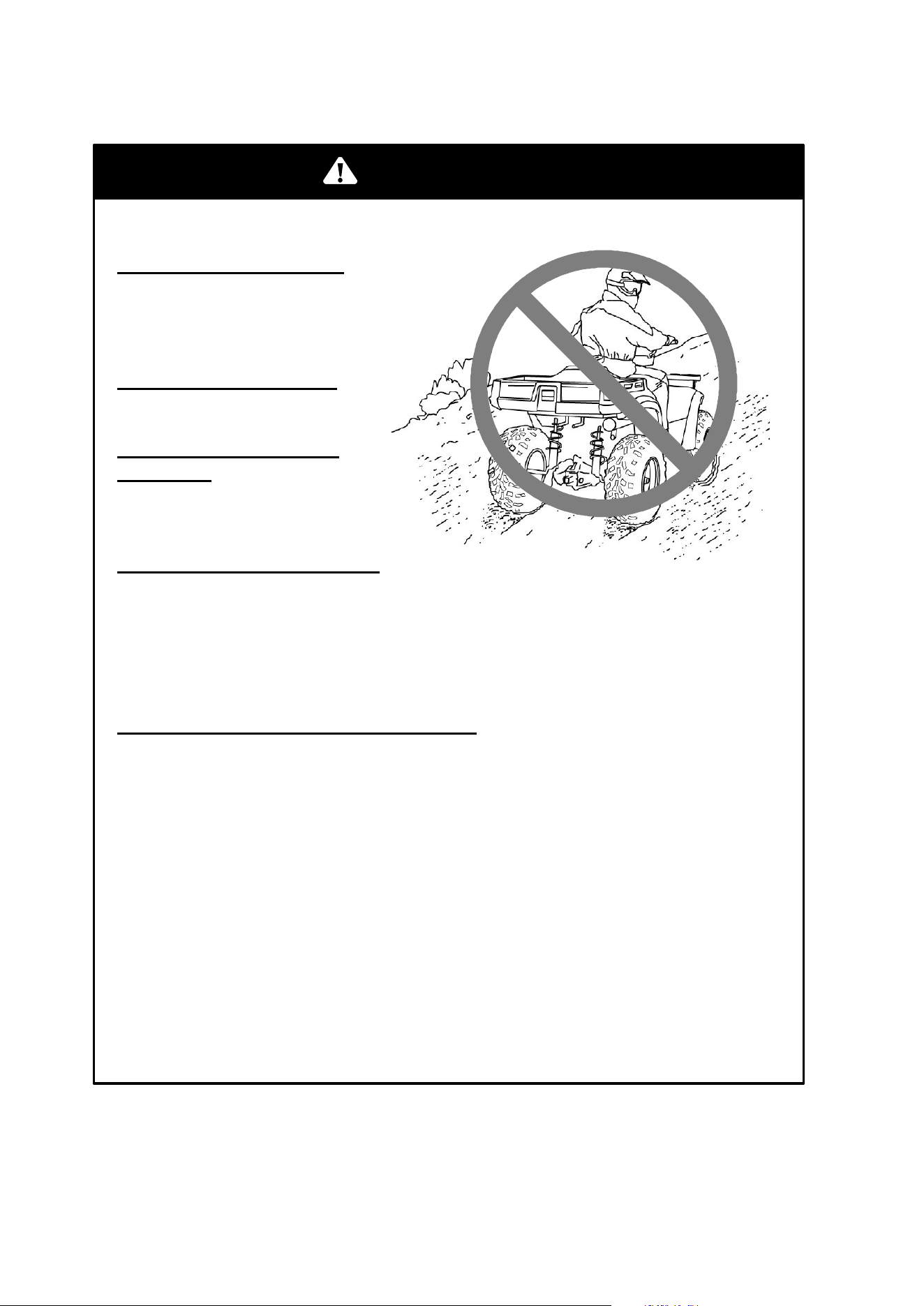
WARNING
Improper vehicle use can result in SEVERE INJURY or DEATH.
READ OWNER'S MANUAL.
FOLLOW ALL INSTRUCTIONS AND WARNINGS.
ALWAYS USE
AN APPROVED
HELMET AND
PROTECTIVE
GEAR
NEVER USE
ON PUBLIC
ROADS
NEVER CARRY
PASSENGERS
NEVER USE
WITH DRUGS
OR ALCOHOL
Operate without proper training or instruction.
Operate on public roads. A collision can occur with another vehicle.
Operate at speeds too fast for your skills or the conditions.
Use ALCOHOL or DRUGS before or while operating this vehicle.
Carry Passengers.
ALWAYS:
Avoid paved surfaces, which may adversely affect handling and control.
Use proper RIDING TECHNIQUES to avoid vehicle overturns on hills
and rough terrain, and in turns.
Wear eye protection, helmet and protective apparel.
NEVER:
WARNING
The engine exhaust from this
product contains chemicals known
to cause cancer, birth defects or
other reproductive harm.
A card containing important ATV safety information should be
attached to the owner’s manual on the next page. If you cannot
locate this card, or if it has been removed, please call
1-800-342-3764 for assistance.

1
We’ve created a web site just for YOU!
S
Technical tips
S
New product introductions
S
Event schedules
S
Parts and Service Manual information
S
Exciting details about The Way Out
Check it out...
www.polarisindustries.com/owner

2
All information in this manual is based on the latest product data and specifications
available at the time of printing. Polaris Industries Inc. reserves the right to make product
changes and improvements that may affect illustrations or explanations.
No part of this manual shall be reproduced or used without the written permission of
Polaris Industries Inc.
Copyright 2002
Polaris Industries Inc.
All Rights Reserved Printed in the U.S.A.

3
WELCOME
Thank you for purchasing a Polaris vehicle, and welcome to our
world-wide family of Polaris owners. We proudly produce an exciting
line of utility and recreational products.
Polaris Recreational and Utility Vehicles
S Snowmobiles
S All-terrain vehicles (ATVs)
S Watercraft
S Victory motorcycles
S RANGER utility vehicles
Polaris Professional Series Workmobiles
S Utility Task Vehiclest (UTVs)
S Personal Task Vehiclest (PTVs)
S All-Surface Loaders (ASLs)
We believe Polaris sets a standard of excellence for all utility and
recreational vehicles manufactured in the world today. Many years of
experience have gone into the engineering, design, and development of
your Polaris vehicle, making it the finest machine we’ve ever
produced.
For safe and enjoyable operation of your vehicle, be sure to follow the
instructions and recommendations in this owner’s manual. Your
manual contains instructions for minor maintenance, but information
about major repairs is outlined in the Polaris Service Manual and
should be performed only by a Factory Certified Master Service Dealer
(MSD) Technician.
Your Polaris dealer knows your vehicle best and is interested in your
total satisfaction. Be sure to return to your dealership for all of your
service needs during, and after, the warranty period.
We also take great pride in our Parts Apparel and Accessories (PAA)
products, available through our online store at www.purepolaris.com.
Have your accessories and clothing delivered right to your door!
Polaris, Polaris The Way Out, and Workmobiles are registered
trademarks of Polaris Industries Inc.

4

5
TABLE OF CONTENTS
WELCOME 3. . . . . . . . . . . . . . . . . . . . . . . . . . . . . . . . . . . . . . . .
TABLE OF CONTENTS 5. . . . . . . . . . . . . . . . . . . . . . . . . . . . .
VEHICLE IDENTIFICATION NUMBERS 6. . . . . . . . . . . . . . .
SAFETY 7. . . . . . . . . . . . . . . . . . . . . . . . . . . . . . . . . . . . . . . . . .
FEATURES AND CONTROLS 37. . . . . . . . . . . . . . . . . . . . . .
OPERATION 53. . . . . . . . . . . . . . . . . . . . . . . . . . . . . . . . . . . . .
EMISSION CONTROL SYSTEMS 74. . . . . . . . . . . . . . . . . . .
MAINTENANCE AND LUBRICATION 75. . . . . . . . . . . . . . . .
POLARIS PRODUCTS 121. . . . . . . . . . . . . . . . . . . . . . . . . . . .
TROUBLESHOOTING 122. . . . . . . . . . . . . . . . . . . . . . . . . . . .
SPECIFICATIONS 126. . . . . . . . . . . . . . . . . . . . . . . . . . . . . . . .
WARRANTY 130. . . . . . . . . . . . . . . . . . . . . . . . . . . . . . . . . . . . .
INDEX 137. . . . . . . . . . . . . . . . . . . . . . . . . . . . . . . . . . . . . . . . . .
6
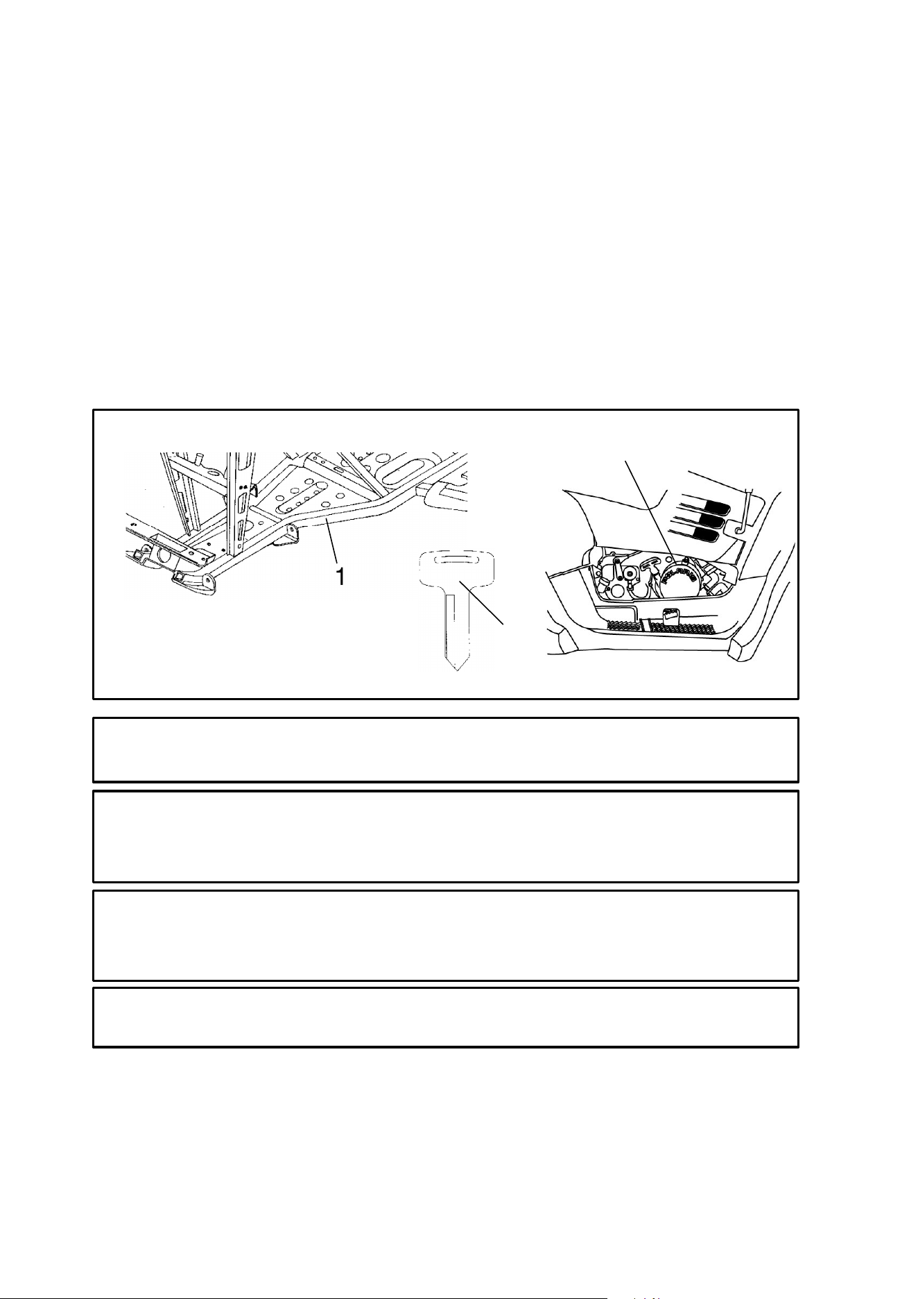
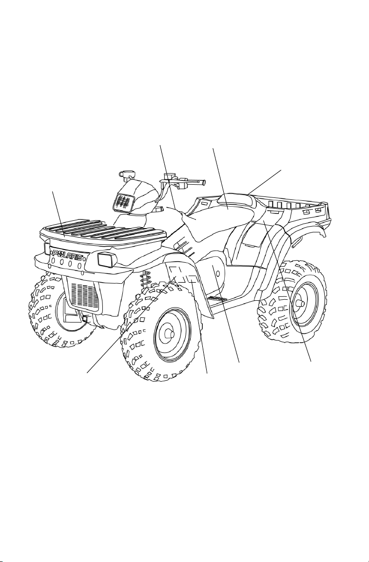
VEHICLE IDENTIFICATION NUMBERS
The vehicle frame vehicle identification number (VIN)(1) and engine
serial number (2) are important for model identification when
registering your vehicle, when obtaining insurance, and when ordering
replacement parts. If your vehicle is stolen, these numbers are essential
to the recovery and identification of your vehicle.
Remove the spare key and store it in a safe place. Your key can be
duplicated only by mating a Polaris key blank with one of your
existing keys. If both keys are lost, the ignition switch must be
replaced. See your Polaris dealer.
NOTE: Record your vehicle’s ID numbers and key number (3) in the
spaces provided.
2
1
31XX
3
Frame VIN:
Engine Serial Number (right front side of engine crankcase):
Vehicle Model Number:
Key Number:

7
SAFETY
Operator Safety
Age Restrictions
This vehicle is an ADULT VEHICLE ONLY. Operation is prohibited
for anyone under 16 years of age.
Know Your Vehicle
As the operator of the vehicle, you are responsible for your personal
safety, the safety of others, and the protection of our environment.
Read and understand your owner’s manual, which includes valuable
information about all aspects of your vehicle, including safe operating
procedures.
Safety Training
When you purchased your new ATV, your dealer offered a hands-on
safety training course that covers all aspects of vehicle safety. You were
also provided with printed materials that explain safe operating
procedures. You should review this information on a regular basis.
If you purchased a used Polaris ATV from a party other than a Polaris
dealer, you can request this free safety training from any authorized
Polaris dealer.
A Polaris ATV is an off-road vehicle. Familiarize yourself with all laws
and regulations concerning the operation of this vehicle in your area.
We strongly advise you to strictly follow the recommended
maintenance program outlined in your owner’s manual. This
preventive maintenance program is designed to ensure that all critical
components on your vehicle are thoroughly inspected at specific
intervals.
WARNING
Failure to follow the warnings contained in this manual can result
in severe injury or death.
A Polaris ATV is not a toy and can be hazardous to operate. This
vehicle handles differently than other vehicles, such as
motorcycles and cars. A collision or rollover can occur quickly,
even during routine maneuvers like turning, or driving on hills or
over obstacles, if you fail to take proper precautions.
Read and understand your owner’s manual and all warnings
before operating a Polaris ATV.
8
SAFETY
Operator Safety
The following signal words and symbols appear throughout this
manual and on your ATV. Your safety is involved when these words
and symbols are used. Become familiar with their meanings before
reading the manual.
The safety alert symbol, on your ATV or in this manual, alerts you
to the potential for personal injury.
The safety alert warning indicates a potential hazard that may result
in serious injury or death.
The safety alert caution indicates a potential hazard that may result
in minor personal injury or damage to the machine.
CAUTION
NOTE
A note will alert you to important information or instructions.
A caution indicates a situation that may result in damage to the
machine.
CAUTION
WARNING

9
SAFETY
Operator Safety
S Read this manual and all labels carefully, and follow the operating
procedures described.
S Never operate an ATV without proper instruction. Take a training
course. Beginners should receive training from a certified instructor.
Contact an authorized Polaris ATV dealer or call Polaris at
1-800-342-3764 to find out about the training courses nearest you.
S Never allow anyone under 16 years of age to operate this ATV.
S Never permit a guest to operate the ATV unless the guest has read
this manual and all product labels and has completed a certified safe-
ty training course.
S Always avoid operating an ATV on paved surfaces, including side-
walks, driveways, parking lots, and streets.
S Never operate an ATV on a public street, road or highway, including
a dirt or gravel road.
S Never operate an ATV without wearing an approved helmet that fits
properly. Always wear eye protection (goggles or face shield),
gloves, boots, a long-sleeved shirt or jacket, and long pants.
S Never consume alcohol or drugs before or while operating an ATV.
S Never operate at excessive speeds. Travel at speeds appropriate for
the terrain, visibility and operating conditions, and your experience.
S Never attempt wheelies, jumps or other stunts.
S Always inspect your ATV before each use to make sure it’s in safe
operating condition. Always follow the inspection and maintenance
procedures and schedules outlined in your owner’s manual.
S Always keep both hands on the handlebars and both feet on the foot-
rests of the ATV during operation.
S Always travel slowly and use extra caution when operating on unfa-
miliar terrain. Be alert to changing terrain conditions.
S Never operate on excessively rough, slippery, or loose terrain.
S Always follow proper turning procedures as described in this manu-
al. Practice turning at low speeds before attempting to turn at faster
speeds. Do not turn at excessive speeds.
WARNING
Serious injury or death can result if you do not follow these
instructions and procedures, which are outlined in further detail
within your owner’s manual.

10
SAFETY
Operator Safety
S Always have the ATV inspected by an authorized Polaris dealer if
it’s been involved in an accident.
S Never operate on hills too steep for the ATV or for your abilities.
Practice on smaller hills before attempting larger hills.
S Always follow proper procedures for climbing hills. Check the ter-
rain carefully before ascend a hill. Never climb hills with excessive-
ly slippery or loose surfaces. Shift your weight forward. Never open
the throttle suddenly or make sudden gear changes. Never go over
the top of a hill at high speed.
S Always follow proper procedures for going downhill and for braking
on hills. Check the terrain carefully before you start down a hill.
Shift your weight backward. Never go down a hill at high speed.
Avoid going down a hill at an angle, which would cause the vehicle
to lean sharply to one side. Travel straight down the hill when pos-
sible.
S Always follow proper procedures for crossing the side of a hill.
Avoid hills with excessively slippery or loose surfaces. Shift your
weight to the uphill side of the ATV. Never attempt to turn the ATV
around on any hill until you’ve mastered (on level ground) the turn-
ing technique outlined in this manual. Avoid crossing the side of a
steep hill when possible.
S Always use proper procedures if you stall or roll backwards while
climbing a hill. To avoid stalling, maintain a steady speed when
climbing a hill. If you stall or roll backwards, follow the special pro-
cedure for braking described in this manual. Always dismount on the
uphill side, or to either side if the ATV is pointed straight uphill.
Turn the ATV around and remount following the procedure de-
scribed in this manual.
S Always check for obstacles before operating in a new area. Never
attempt to operate over large obstacles, such as rocks or fallen trees.
Always follow proper procedures when operating over obstacles as
described in this manual.
S Always be careful of skidding or sliding. On slippery surfaces like
ice, travel slowly and use extra caution to reduce the chance of skid-
ding or sliding out of control.
S Avoid operating the ATV through deep or fast-flowing water. If it’s
unavoidable, travel slowly, balance your weight carefully, avoid sud-
den movements, and maintain a slow and steady forward motion. Do
not make sudden turns or stops, and do not make sudden throttle
changes.

11
SAFETY
Operator Safety
S Wet brakes may have reduced stopping ability. Test your brakes after
leaving water. If necessary, apply them lightly several times to allow
friction to dry out the pads.
S Always check for obstacles or people behind the ATV before operat-
ing in reverse. When it’s safe to proceed in reverse, move slowly and
avoid turning at sharp angles.
S Always use the size and type of tires specified for your ATV, and
always maintain proper tire pressure.
S Never modify an ATV through improper installation or use of acces-
sories.
S Never exceed the stated load capacity for your ATV. Cargo must be
properly distributed and securely attached. Reduce speed and follow
the instructions in this manual for carrying cargo or towing. Allow a
greater distance for braking.
S Always remove the ignition key when the vehicle is not in use to
prevent unauthorized use or accidental starting.
FOR MORE INFORMATION ABOUT ATV SAFETY, call the Con-
sumer Product Safety Commission at 1-800-638-2772, or call
Polaris at 1-800-342-3764.
Equipment Modifications
We are concerned for the safety of our customers and for the general
public. Therefore, we strongly recommend that consumers do not
install on a Polaris ATV any equipment that may increase the speed or
power of the vehicle, or make any other modifications to the vehicle
for these purposes. Any modifications to the original equipment of the
vehicle create a substantial safety hazard and increase the risk of bodily
injury.
The warranty on your Polaris ATV is terminated if any equipment has
been added to the vehicle, or if any modifications have been made to
the vehicle, that increase its speed or power.
NOTE: The addition of certain accessories, including (but not limited
to) mowers, blades, tires, sprayers, or large racks, may change the
handling characteristics of the vehicle. Use only Polaris-approved
accessories, and familiarize yourself with their function and effect on
the vehicle.
12
SAFETY
Operator Safety
POTENTIAL HAZARD
Operating this ATV without proper instruction.
WHAT CAN HAPPEN
The risk of an accident is greatly increased if the operator
does not know how to operate the ATV properly in different
situations and on different types of terrain.
HOW TO AVOID THE HAZARD
Beginning and inexperienced operators should complete the
certified training course offered by Polaris. Operators should
regularly practice the skills learned in the course and the
operating techniques described in the owner’s manual.
For more information about the training course, contact an
authorized ATV dealer or call Polaris at 1-800-342-3764.
POTENTIAL HAZARD
Failure to follow the age recommendations for this ATV.
WHAT CAN HAPPEN
Severe injury and/or death could occur if a child under the
minimum age recommendation operates an ATV.
Even though a child may be within the recommended age group
for operating some ATVs, he/she may not have the skills,
abilities, or judgment needed to operate an ATV safely and could
be susceptible to accident or injury.
HOW TO AVOID THE HAZARD
No one under the age of 16 should operate a Polaris ATV.
WARNING
WARNING
13
SAFETY
Operator Safety
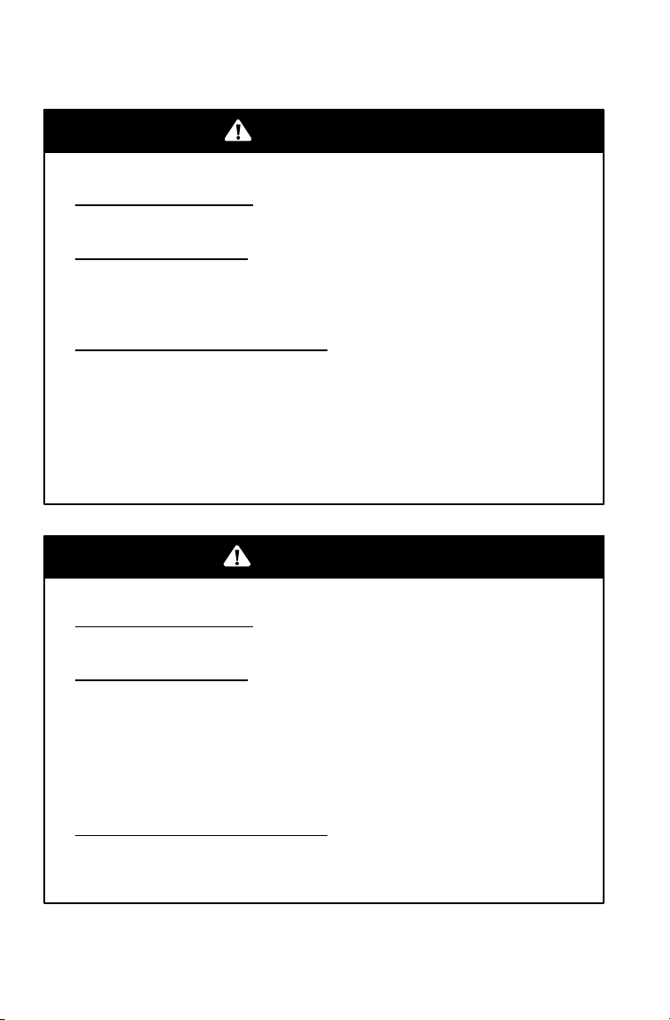
POTENTIAL HAZARD
Carrying a passenger on an ATV.
WHAT CAN HAPPEN
Carrying a passenger greatly reduces
the operator’s ability to balance and
control the ATV, which could cause an
accident and injury to the operator
and/or passenger.
HOW TO AVOID THE HAZARD
Never carry a passenger. The purpose of the long seat is to
allow the operator to shift position as needed during operation.
It is not intended for carrying passengers.
WARNING
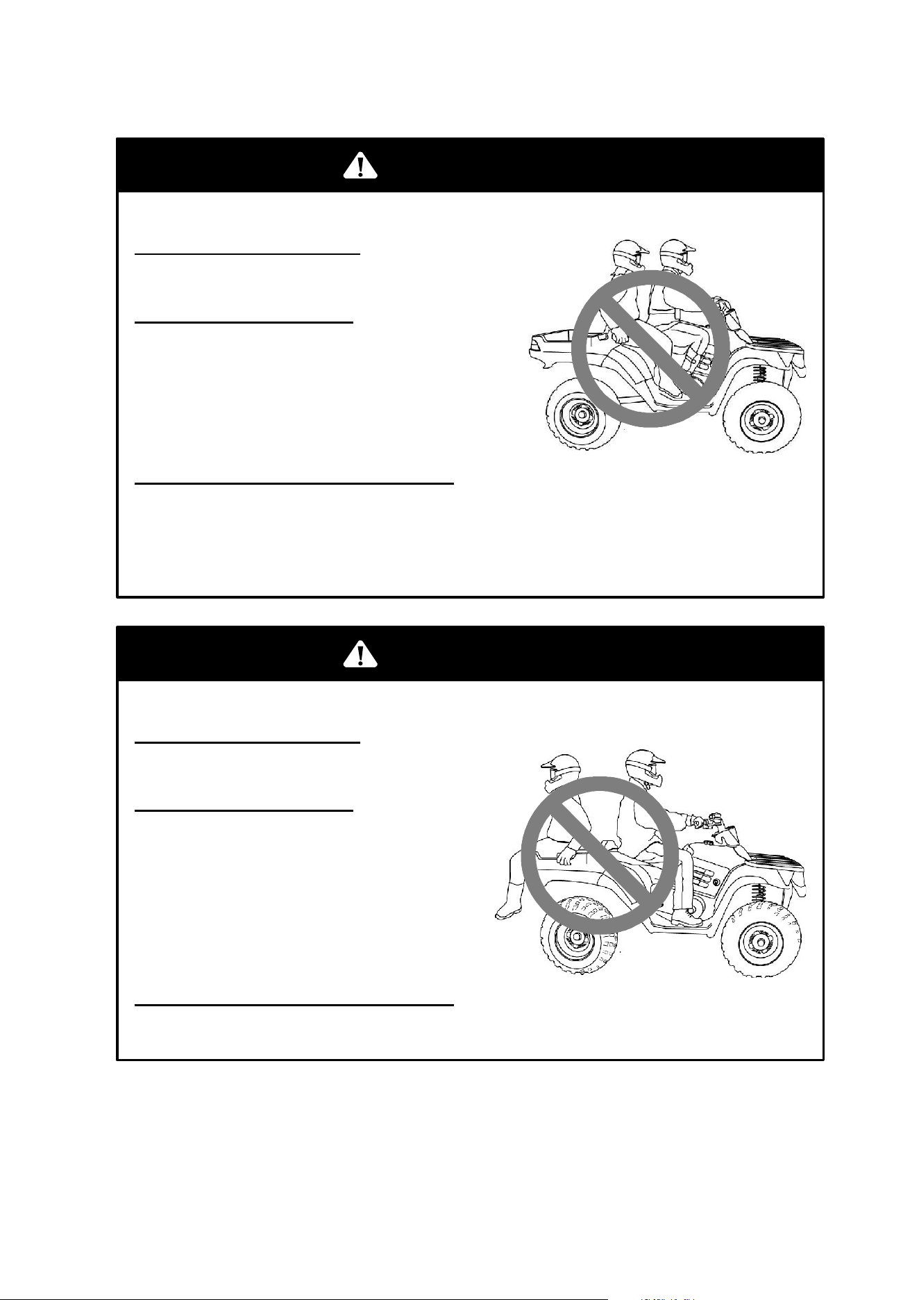
POTENTIAL HAZARD
Carrying a passenger in the cargo box.
WHAT CAN HAPPEN
A passenger riding in the cargo
box could be ejected from the
vehicle unexpectedly or may
contact moving components, both
of which can result in severe injury
or death.
HOW TO AVOID THE HAZARD
Never allow passengers to ride in the cargo box.
WARNING
14
SAFETY
Operator Safety
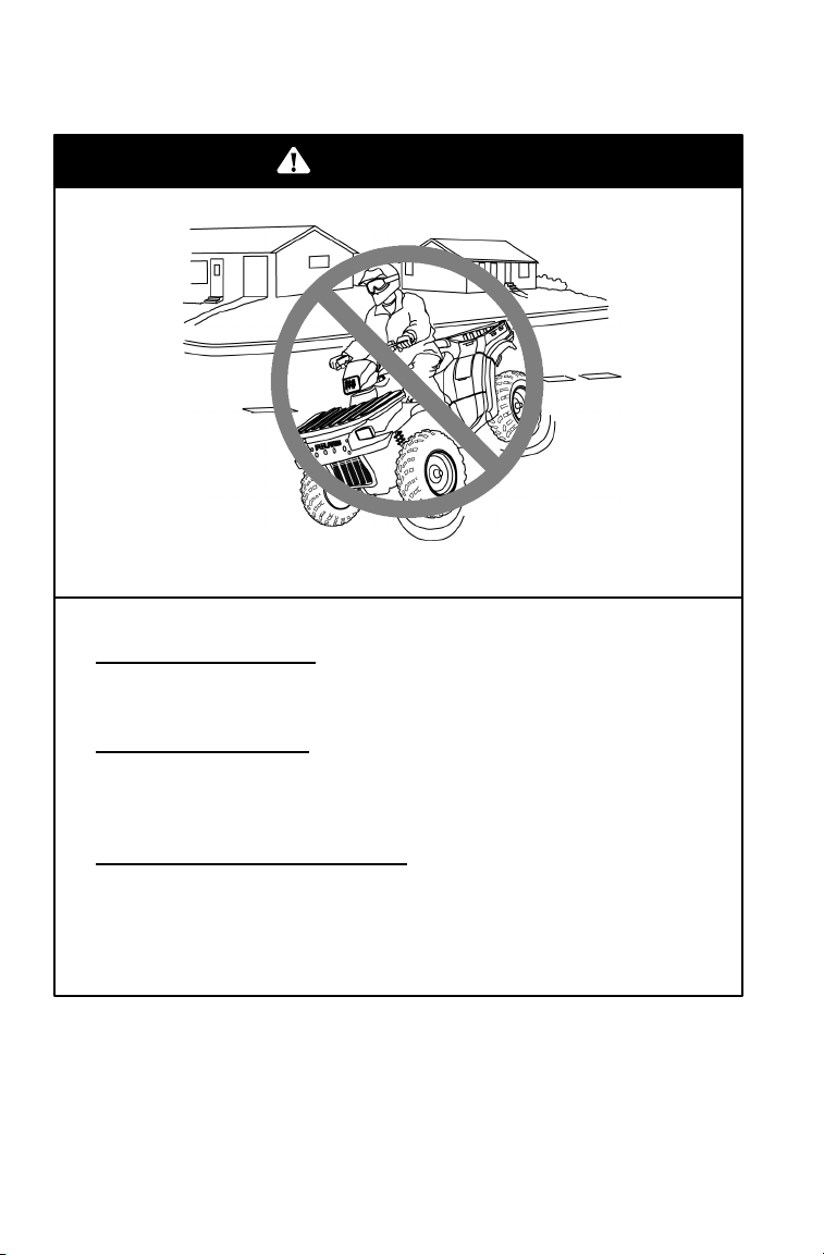
POTENTIAL HAZARD
Operating an ATV on paved surfaces, including sidewalks,
paths, parking lots, and driveways.
WHAT CAN HAPPEN
ATV tires are designed for off-road use. Operating on paved
surfaces may seriously affect the handling and control of the
ATV and could result in loss of control, accident, and/or injury.
HOW TO AVOID THE HAZARD
Avoid operating the ATV on pavement. If it’s unavoidable,
travel slowly and avoid sudden turns or stops.
WARNING
15
SAFETY
Operator Safety
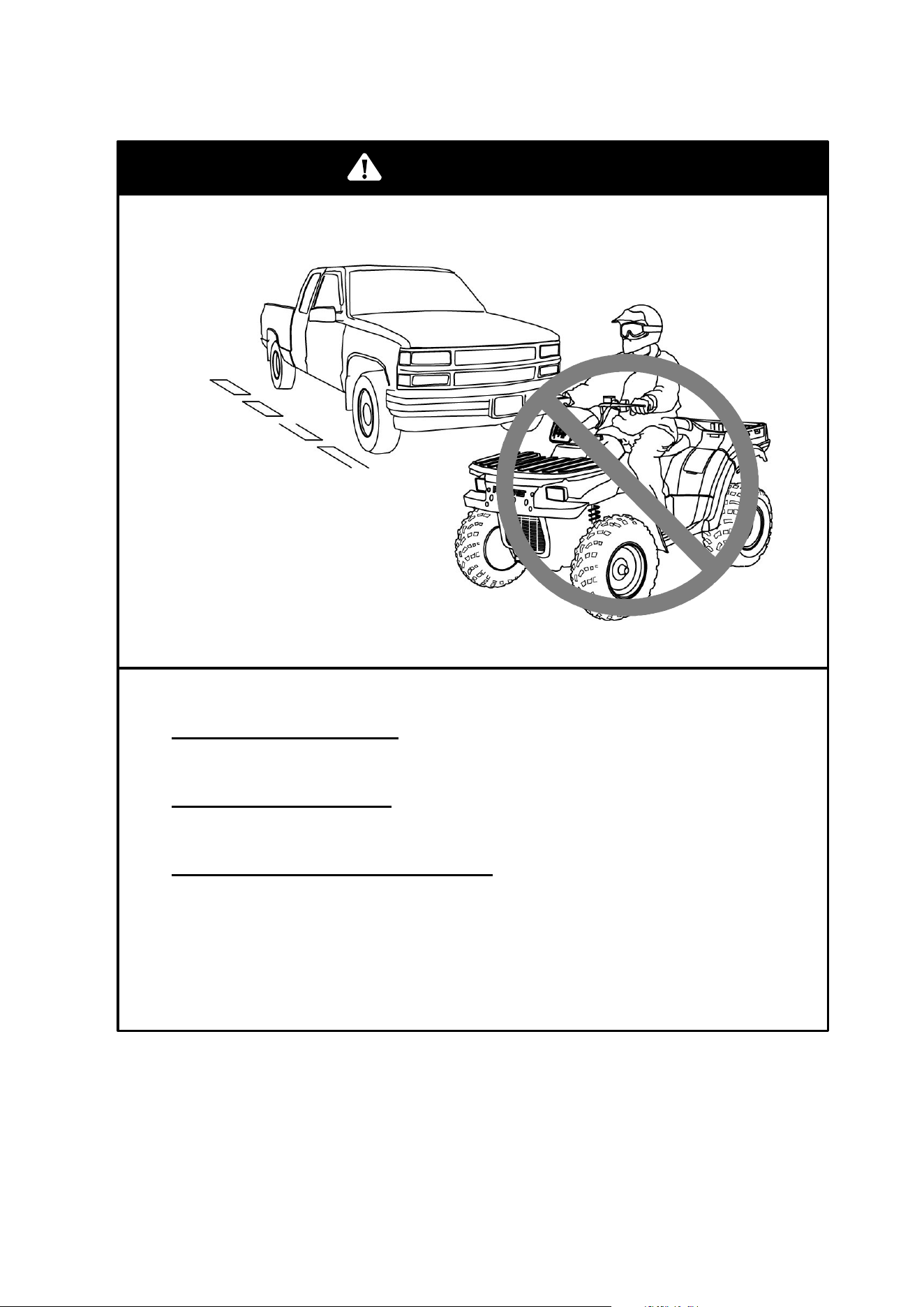
POTENTIAL HAZARD
Operating this ATV on public streets, roads or highways.
WHAT CAN HAPPEN
The ATV could collide with another vehicle.
HOW TO AVOID THE HAZARD
Never operate the ATV on any public street, road or highway,
including dirt and gravel roads. In many states it’s illegal to
operate ATVs on public streets, roads and highways.
WARNING
16
SAFETY
Operator Safety
POTENTIAL HAZARD
Operating this ATV without wearing an approved helmet, eye
protection and protective clothing.
WHAT CAN HAPPEN
Operating an ATV without an approved helmet increases the
risk of a severe head injury or death in the event of an
accident.
Operating without eye protection could result in an accident
and could increase the chance of a severe injury in the event
of an accident.
HOW TO AVOID THE HAZARD
Always wear an approved helmet that fits properly.
Always wear eye protection (goggles or face shield), gloves,
boots, long-sleeved shirt or jacket, and long pants.
WARNING
17
SAFETY
Operator Safety
POTENTIAL HAZARD
Operating the ATV after consuming alcohol or drugs.
WHAT CAN HAPPEN
Consumption of alcohol and/or drugs could seriously affect
operator judgment. Reaction time may be slower and operator
balance and perception could be affected.
Consuming alcohol and/or drugs before or while operating an
ATV could result in an accident causing severe injury or death.
HOW TO AVOID THE HAZARD
Never consume alcohol or drugs before or while operating an
ATV.
POTENTIAL HAZARD
Operating the ATV at excessive speeds.
WHAT CAN HAPPEN
Excessive speed increases the operator’s chance of losing
control of the ATV, which can result in an accident.
HOW TO AVOID THE HAZARD
Always operate the ATV at a speed that’s proper for the terrain,
visibility and operating conditions, and your experience.
WARNING
WARNING
18
SAFETY
Operator Safety
POTENTIAL HAZARD
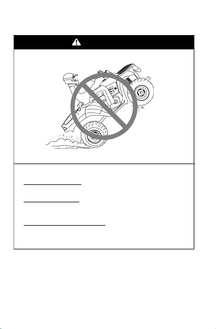
Attempting wheelies, jumps and other stunts.
WHAT CAN HAPPEN
Attempting stunts increases the chance of an accident, including
an overturn.
HOW TO AVOID THE HAZARD
Never attempt wheelies, jumps, or other stunts. Avoid exhibition
driving.
WARNING
19
SAFETY
Operator Safety
POTENTIAL HAZARD
Failure to inspect the ATV before operating.
Failure to properly maintain the ATV.
WHAT CAN HAPPEN
Poor maintenance increases the possibility of an accident or
equipment damage.
HOW TO AVOID THE HAZARD
Always inspect your ATV before each use to make sure it’s in
safe operating condition.
Always follow the inspection and maintenance procedures and
schedules described in the owner’s manual.
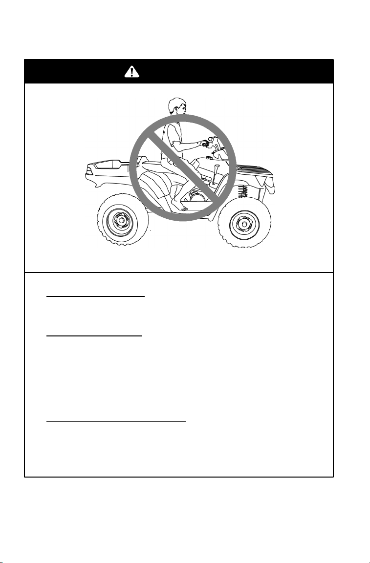
POTENTIAL HAZARD
Removing hands from the handlebars or feet from the
footrests during operation.
WHAT CAN HAPPEN
Removing even one hand or foot can reduce ability to
control the vehicle or could cause loss of balance and
ejection from the ATV.
If the operator’s foot is not firmly planted on the footrest, it
could come into contact with the rear wheels and lead to
accident or injury.
HOW TO AVOID THE HAZARD
Always keep both hands on the handlebars and both feet
on the footrests of the ATV during operation.
WARNING
WARNING
20
SAFETY
Operator Safety
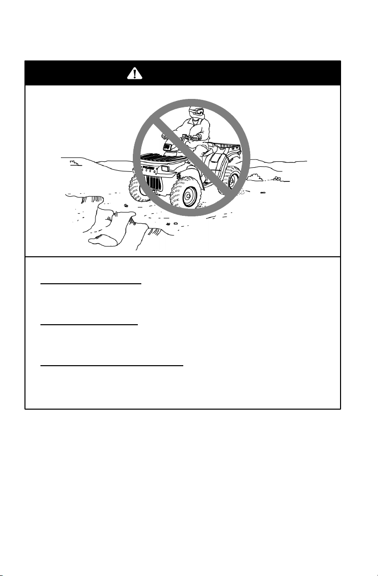
POTENTIAL HAZARD
Failure to use extra caution when operating the ATV on unfamiliar
terrain.
WHAT CAN HAPPEN
Unfamiliar terrain may contain hidden rocks, bumps, or holes that
could cause loss of control or overturn.
HOW TO AVOID THE HAZARD
Travel slowly and use extra caution when operating on unfamiliar
terrain. Always be alert to changing terrain conditions.
WARNING
21
SAFETY
Operator Safety
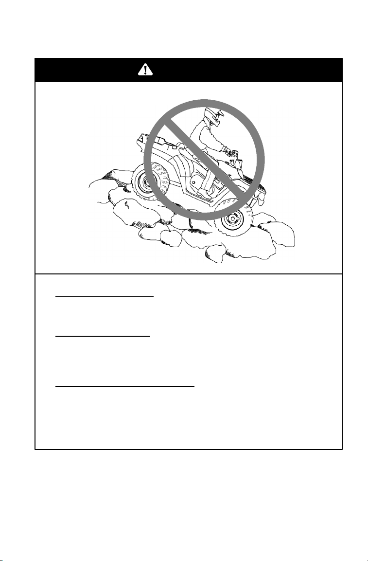
POTENTIAL HAZARD
Failure to use extra caution when operating on excessively
rough, slippery or loose terrain.
WHAT CAN HAPPEN
Operating on excessively rough, slippery or loose terrain could
cause loss of traction or loss of control, which could result in an
accident or overturn.
HOW TO AVOID THE HAZARD
Do not operate on excessively rough, slippery or loose terrain
until you’ve learned and practiced the skills necessary to
control the ATV on such terrain.
Always use extra caution on rough, slippery or loose terrain.
WARNING
22
SAFETY
Operator Safety
POTENTIAL HAZARD
Turning improperly.
WHAT CAN HAPPEN
Improper turns could cause loss of control and lead to a collision
or overturn.
HOW TO AVOID THE HAZARD
Always follow proper procedures for turning as described in the
owner’s manual.
Practice turning at slow speeds before attempting to turn at
faster speeds.
Never turn at excessive speed.
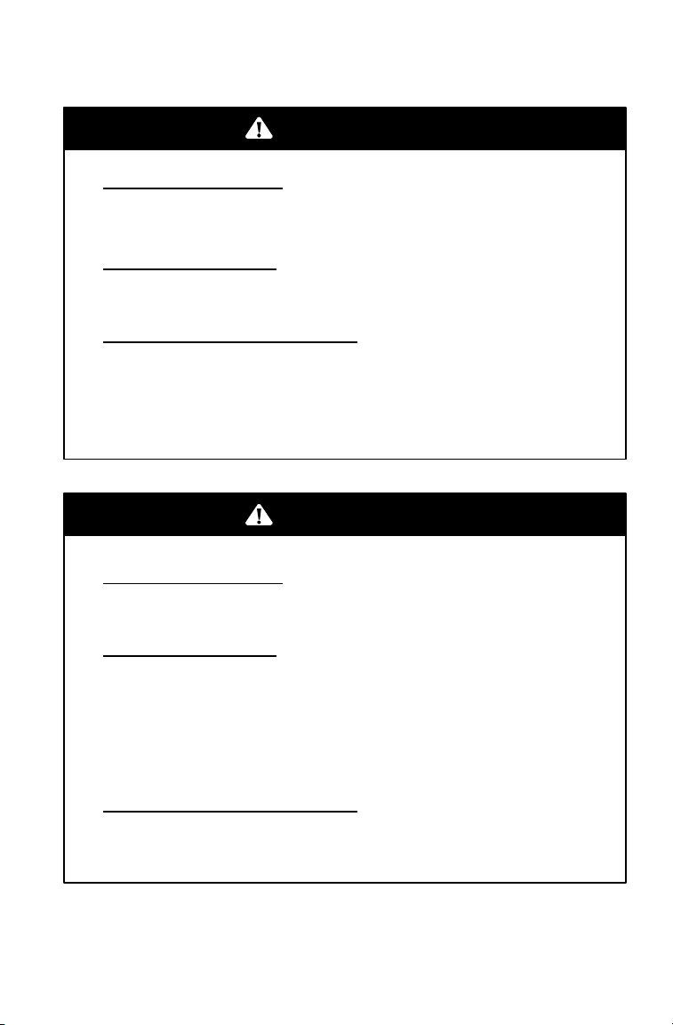
POTENTIAL HAZARD
Operating on excessively steep hills.
WHAT CAN HAPPEN
The vehicle may overturn.
HOW TO AVOID THE HAZARD
Never operate on hills too steep for the ATV or for your
abilities. Never operate the ATV on hills steeper than 25_.
Practice on smaller hills before attempting large hills.
WARNING
WARNING
23
SAFETY
Operator Safety
POTENTIAL HAZARD
Climbing hills improperly.
WHAT CAN HAPPEN
Improper hill climbing could cause loss of control or overturn.
HOW TO AVOID THE HAZARD
Always follow proper procedures for climbing hills as described
in the owner’s manual.
Always check the terrain carefully before ascending any hill.
Never operate the ATV on hills steeper than 25_.
Never climb hills with excessively slippery or loose surfaces.
Shift your weight forward.
Never open the throttle suddenly while traveling uphill. The ATV
could flip over backwards.
Never go over the top of any hill at high speed. An obstacle, a
sharp drop, or another vehicle or person could be on the other
side of the hill.
WARNING
24
SAFETY
Operator Safety
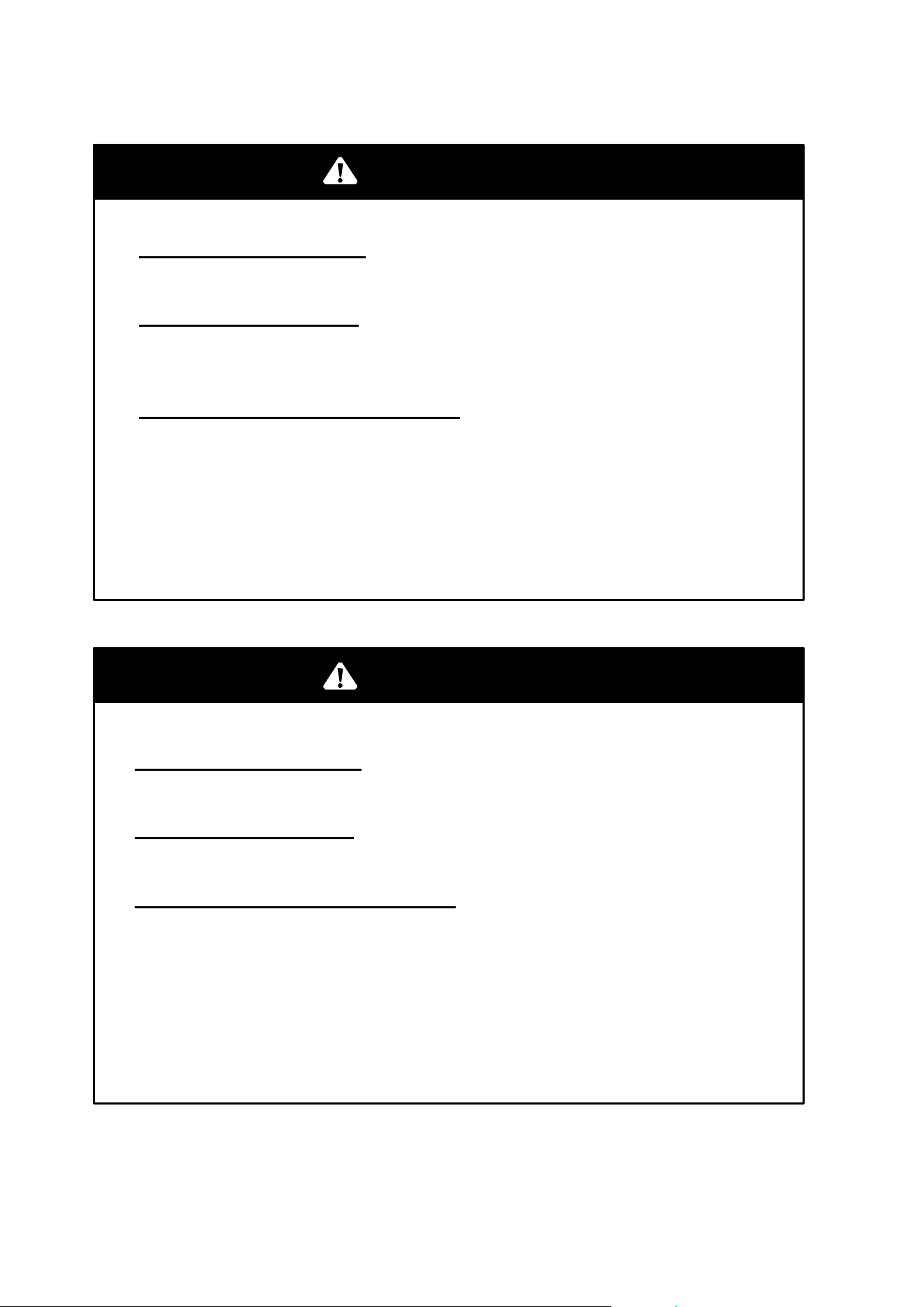
POTENTIAL HAZARD
Traveling downhill improperly.
WHAT CAN HAPPEN
Improperly descending a hill could cause loss of control or
overturn.
HOW TO AVOID THE HAZARD
Always follow proper procedures for traveling down hills as
described in the owner’s manual. NOTE: A special technique
is required when braking while traveling downhill. See page
65.
Always check the terrain carefully before you descending a hill.
Shift your weight backward.
Never travel down a hill at high speed.
Avoid traveling down a hill at an angle, which would cause the
vehicle to lean sharply to one side. Travel straight down the
hill when possible.
WARNING
25
SAFETY
Operator Safety
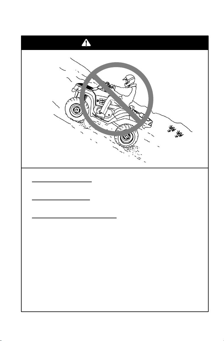
POTENTIAL HAZARD
Improperly crossing hills and turning on hills.
WHAT CAN HAPPEN
Improperly crossing or turning as hills could cause loss of control
or overturn.
HOW TO AVOID THE
HAZARD
Never attempt to turn the ATV around on any hill until you’ve
mastered the turning technique (on level ground) as described in
the owner’s manual. See page 66. Use extra caution when
turning on any hill.
Avoid crossing the side of a steep hill.
When crossing the side of a hill:
Always follow proper procedures as described in the owner’s
manual.
Avoid hills with excessively slippery or loose surfaces.
Shift your weight to the uphill side of the ATV.
WARNING
26
SAFETY
Operator Safety
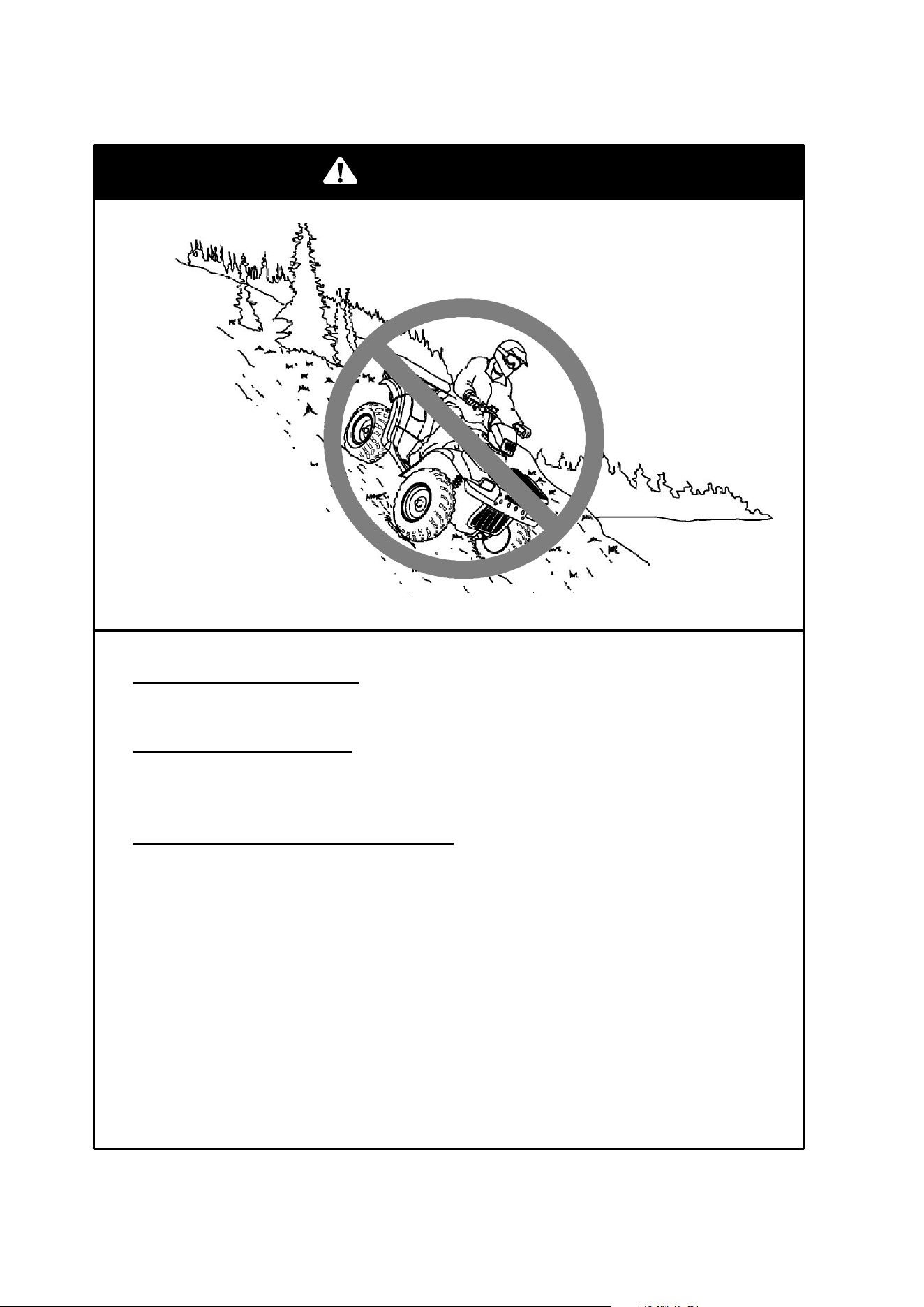
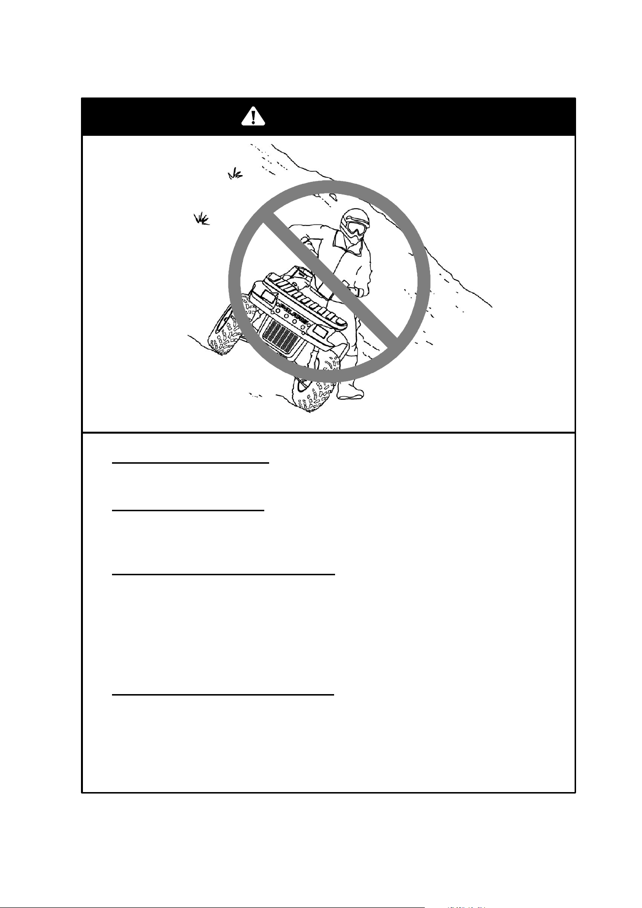
POTENTIAL HAZARD
Stalling, rolling backwards or
improperly dismounting while
climbing a hill.
WHAT CAN HAPPEN
The vehicle could overturn.
HOW TO AVOID THE
HAZARD
Maintain steady speed when
climbing a hill.
If all forward speed is lost:
Keep your weight uphill.
Apply the front brake (or the single lever brake, gradually).
When fully stopped, apply the rear brake as well, then lock the
parking brake.
If the ATV begins rolling
backwards:
Keep weight uphill.
Never apply engine power.
Never apply the rear brake while rolling backwards.
Apply the front brake (or single-lever brake) gradually.
When fully stopped, apply the rear brake as well, and then lock
the parking brake.
Dismount on uphill side, or to either side if ATV is pointed
straight uphill.
Turn the ATV around and remount, following the procedure
described in the owner’s manual. See page 66.
WARNING
27
SAFETY
Operator Safety
POTENTIAL HAZARD
Improperly operating over obstacles.
WHAT CAN HAPPEN
Operating over obstacles could cause loss of control or overturn.
HOW TO AVOID THE HAZARD
Before operating in a new area, check for obstacles.
Avoid operating over large obstacles such as rocks and fallen
trees when possible. If unavoidable, use extreme caution and
always follow proper procedures as outlined in the owner’s
manual.
POTENTIAL HAZARD
Skidding or sliding.
WHAT CAN HAPPEN
Skidding or sliding can cause loss of control.
If the tires regain traction unexpectedly, the ATV could overturn.
HOW TO AVOID THE HAZARD
On slippery surfaces such as ice, travel slowly and use extra
caution to reduce the chance of skidding or sliding out of control.
WARNING
WARNING
28
SAFETY
Operator Safety
POTENTIAL HAZARD
Operating the ATV through deep or fast-flowing water.
WHAT CAN HAPPEN
Tires may float, causing loss of traction and loss of control,
which could lead to an accident or overturn.
HOW TO AVOID THE
HAZARD
Avoid operating the ATV through deep or fast-flowing water.
If it’s unavoidable to enter water that exceeds the
recommended maximum depth (see page 67), travel slowly,
balance your weight carefully, avoid sudden movements, and
maintain a slow and steady forward motion. Do not make
sudden turns or stops, and do not make sudden throttle
changes.
Wet brakes may have reduced stopping ability. Always test
the brakes after leaving water. If necessary, apply them
several times to let friction dry out the pads.
POTENTIAL
HAZARD
Improperly operating in reverse.
WHAT CAN HAPPEN
The ATV could collide with an obstacle or person, resulting in
severe injury.
HOW TO AVOID THE HAZARD
Before shifting into reverse gear, always check for obstacles or
people behind the ATV. When it’s safe to proceed, back
slowly.
WARNING
WARNING
29
SAFETY
Operator Safety
POTENTIAL HAZARD
Operating this ATV with improper tires, or with improper or uneven
tire pressure.
WHAT CAN HAPPEN
Use of improper tires, or operation of the ATV with improper or
uneven tire pressure, could cause loss of control or accident.
HOW TO AVOID THE HAZARD
Always use the size and type of tires specified in the owner’s
manual for the ATV.
Always maintain proper tire pressure.
POTENTIAL HAZARD
Operating the ATV with improper modifications.
WHAT CAN HAPPEN
Improper installation of accessories or modification of the ATV
may cause changes in handling which could lead to an
accident.
HOW TO AVOID THE HAZARD
Never modify the ATV through improper installation or use of
accessories. All parts and accessories added to the vehicle
must be genuine Polaris Industries Inc. or equivalent
components designed for use on this ATV and should be
installed and used according to approved instructions. See
your authorized Polaris ATV dealer for more information.
WARNING
WARNING
30
SAFETY
Operator Safety
POTENTIAL HAZARD
Overloading the ATV or carrying/towing cargo improperly.
WHAT CAN HAPPEN
Overloading and towing can cause changes in vehicle handling,
which could lead to loss of control or an accident.
HOW TO AVOID THE HAZARD
Never exceed the stated load capacity for this ATV.
Cargo should be properly distributed and securely attached.
Reduce speed when carrying cargo or pulling a trailer. Allow a
greater distance for braking.
Always follow the instructions in the owner’s manual for carrying
cargo or pulling a trailer. See page 58.
POTENTIAL HAZARD
Operating on frozen bodies of water.
WHAT CAN HAPPEN
Severe injury or death can result if the ATV and/or the operator
fall through the ice.
HOW TO AVOID THE HAZARD
Never operate the ATV on a frozen body of water. If you’re
confident that the ice is thick enough and sound enough to
support the machine and its operator, as well as the force
created by a moving vehicle, exercise extreme caution.
WARNING
WARNING

31
SAFETY
Operator Safety
After any overturn or accident, have a qualified service dealer
inspect the entire vehicle for possible damage, including (but not
limited to) brakes, throttle and steering systems.
Safe operation of this rider-active vehicle requires good judgement
and physical skills. Persons with cognitive or physical disabilities
who operate this vehicle have an increased risk of overturn and
loss of control, which could result in severe injury or death.
CAUTION
Always keep combustible materials away from the exhaust
system. Exposure to the hot components could result in a fire.
WARNING
WARNING
Leaving the keys in the ignition can lead to unauthorized use of
the vehicle resulting in serious injury or death. Always remove
the ignition key when the vehicle is not in use.
WARNING
32
SAFETY
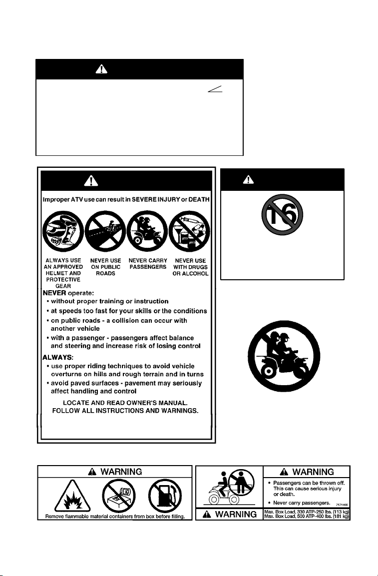
Safety Decals and Locations
Warning decals have been placed on the ATV for your protection.
Read and follow the instructions on each decal carefully. If a decal
becomes illegible or comes off, contact your Polaris dealer to purchase
a replacement. Replacement safety decals are provided by Polaris at no
charge. The part number is printed on the decal.
A
B
C
D
E
F
G
H
33
SAFETY
Safety Decals and Locations
DNever operate this vehicle on HILLS steeper than 25 degrees 25°.
To prevent flipover on hilly terrain, when going up or down, use throttle and
brakes gradually.
DREVERSE operation can be dangerous, even at low speeds. Steering be-
comes difficult. To prevent flipover, avoid sudden braking or sharp turns.
DUse OVERRIDE for reverse speed limiter with caution. To prevent loss of
control, never activate override button with open throttle.
DWhen this ATV is not in operation or unattended, place shift in the park
position.
7079083
E1997, 2000
IF OWNER’S MANUAL IS MISSING, CONTACT
A POLARIS DEALER FOR A REPLACEMENT.
WARNING
WARNING
7171383
A
B
Operating this vehicle if you are under the age
of 16 increases your chance of severe injury
or death.
NEVER operate this vehicle if you are under
age 16.
WARNING
C
H
E
34
SAFETY
Safety Decals and Locations
IMPROPER TIRE PRESSURE OR OVERLOADING can cause loss
of control resulting in SEVERE INJURY OR DEATH.
TIRE PRESSURE IN PSI (KPa):
FRONT 5 (34,5) REAR 5 (34,5)
MAXIMUM WEIGHT CAPACITY (Gross Vehicle Weight)
INCLUDING MACHINE, DRIVER AND CARGO IS
1500 LBS. (680 kg)
Reduce speed and allow greater distance for braking when carrying
cargo. Overloading or carrying tall, off-center, or unsecured loads will
increase your risk of losing control. Loads should be centered, carried
as low as possible in box, and firmly secured to the rack. For stability
on rough or hilly terrain, reduce speed and cargo. Do not block head-
light. Be careful if load extends over the side of the rack or box.
Read Owner’s Manual for more detailed loading information.
7171464
WARNING
IMPROPER TIRE PRESSURE OR OVERLOADING can cause loss
of control resulting in SEVERE INJURY OR DEATH.
TIRE PRESSURE IN PSI (KPa):
FRONT 5 (34,5) REAR 5 (34,5)
MAXIMUM WEIGHT CAPACITY (Gross Vehicle Weight)
INCLUDING MACHINE, DRIVER AND CARGO IS
1300 LBS. (590 kg)
MAXIMUM CARGO CAPACITY 350 LBS. (158 kg)
Reduce speed and allow greater distance for braking when carrying
cargo. Overloading or carrying tall, off-center, or unsecured loads will
increase your risk of losing control. Loads should be centered, carried
as low as possible in box, and firmly secured to the rack. For stability
on rough or hilly terrain, reduce speed and cargo. Do not block head-
light. Be careful if load extends over the side of the rack or box.
Read Owner’s Manual for more detailed loading information.
7171463
WARNING
F
G
DO NOT TOW FROM RACK OR BUMPER. Vehicle damage or tipover may result causing severe injury or
death. Tow only from tow hooks or hitch. Max. combined Front Rack and container Load 90 lbs. (41 kg)
7171465
WARNING
F
ATP 330
ATP 500
35
SAFETY
Safety Decals and Locations
ALL WHEEL
DRIVE
SWITCH
Do not push switch to
engage AWD if the rear
wheels are spinning.
This may cause severe
drive shaft and clutch
damage.
See your Owner’s
Manual.
7079780
MANUFACTURED
BY: POLARIS IND, INC.
DATE:
VIN:
THIS VEHICLE IS AN ALL TERRAIN VEHICLE AND IS NOT
INTENDED FOR USE ON PUBLIC ROADS.
7078470
CE VÉHICULE EST UN VÉHICULE TOUT TERRAIN QUI
NiEST PAS DESTINÉ À ÊTRE UTILISÉ SUR LES CHEMINS
PUBLICS.
7079604
WARNING
Pushing reverse
override button
may cause
sudden in-
creases in pow-
er and traction if
too much
throttle is ap-
plied. Loss of
control or for-
ward flipover
may result, es-
pecially in
AWD. See Own-
er’s Manual.
Canadian Certification Decal
S Operation of this vehicle
without the air filter
element will severely damage
the engine.
S Clean pre-filter element often,
more frequent cleaning
required in dusty conditions.
Do not operate vehicle without
pre-filter.
ATTENTION
Under seat: ATP 330
S Specific
carburetor jetting
7170007
and adjustments are required
depending on temperature
and altitude. See your Owner’s
Manual.
Factory setting:
40_ to 80_ F. at 0-3000 feet
(5_ to 27_ C. at 0-900 meters).
S Operation of this vehicle
without the air filter element
will severely damage the engine.
S Clean pre-filter element often,
more frequent cleaning required
in dusty conditions. Do not
operate vehicle without pre-filter.
S Operation of this vehicle without
engine breather filter(s) can cause
engine damage. Consult owner’s
manual or dealer for details.
ATTENTION
S Specific
carburetor jetting
7079902
and adjustments are required
depending on temperature
and altitude. See your Owner’s
Manual.
Factory setting:
40_ to 80_ F. at 0-3000 feet
(5_ to 27_ C. at 0-900 meters).
Under seat: ATP 500
Moving parts hazard under belt-clutch guard. To
prevent serious injury, do not operate vehicle with
guard removed.
Do not modify engine or clutch. Doing so can cause
part failure, possible imbalance, and excessive engine
RPM which can result in serious injury or death.
NO STEP
7078689
WARNING
D
36
SAFETY
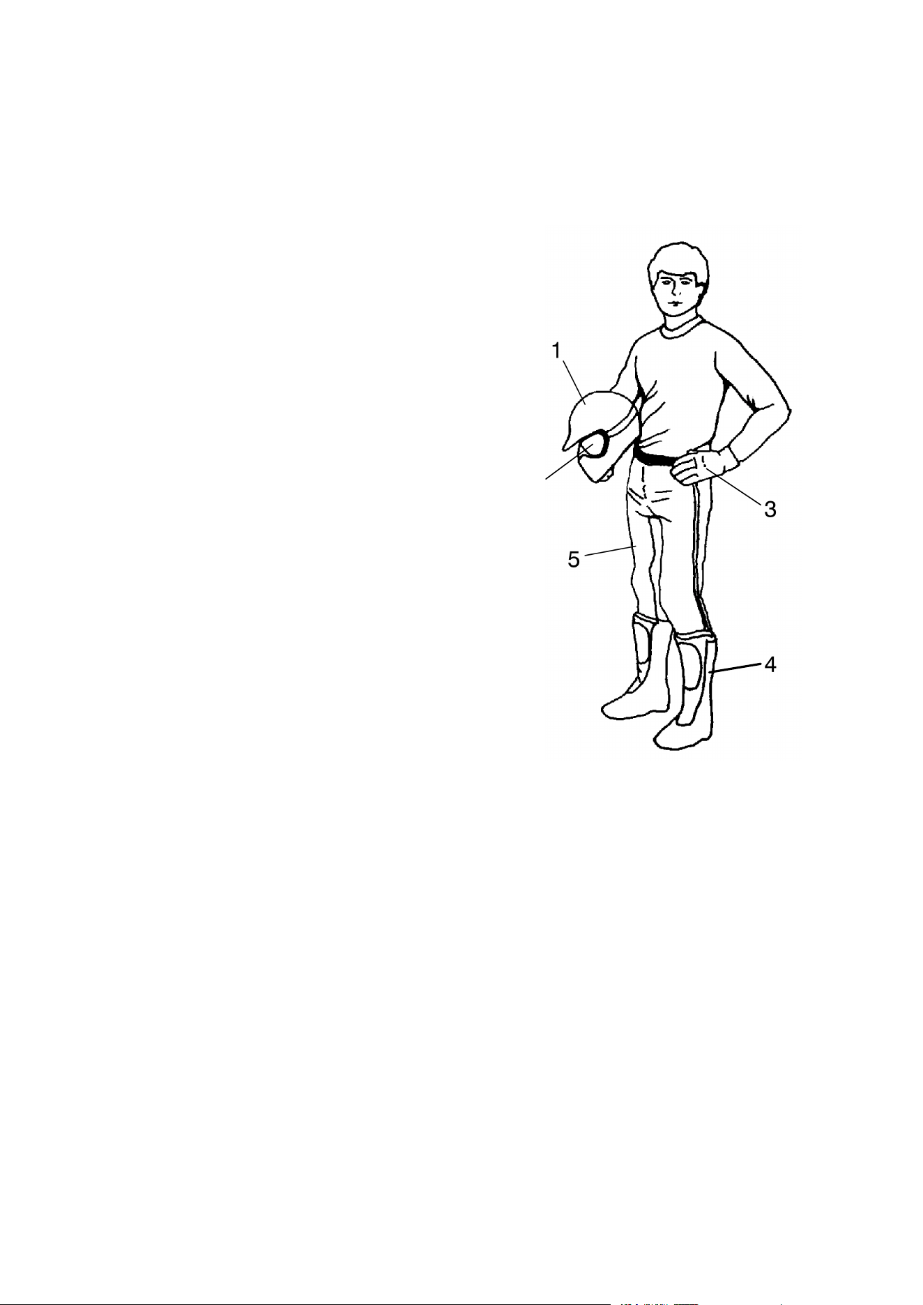
Safe Riding Gear
Always wear clothing suited to the type of riding. ATV riding requires
special protective clothing for comfort and to reduce the chance of
injury.
1. Helmet
Your helmet is the most important piece
of protective gear for safe riding. A
helmet can prevent a severe head injury.
Select an approved helmet that meets or
exceeds your state’s safety standards
and bears either the Department of
Transportation (DOT) label, the
American National Standards Institute
label (ANSI z90.1), or the Snell
Memorial Foundation label.
2. Eye Protection
Do not depend on sunglasses for proper
eye protection. A pair of goggles or a
helmet face shield offer the best
protection for your eyes. They should
be kept clean and be of shatterproof
design (bearing the markings z2.1 or
VESC 8).
3. Gloves
Off-road style gloves with knuckle pads are the best for comfort and
protection.
4. Boots
The best footwear is a pair of strong over-the-calf boots with heels, like
moto-cross boots.
5. Clothing
Always wear long sleeves and long pants to protect arms and legs.
Riding pants with kneepads and a jersey with shoulder pads provide
the best protection.
1
2
3
4
5
37
FEATURES AND CONTROLS
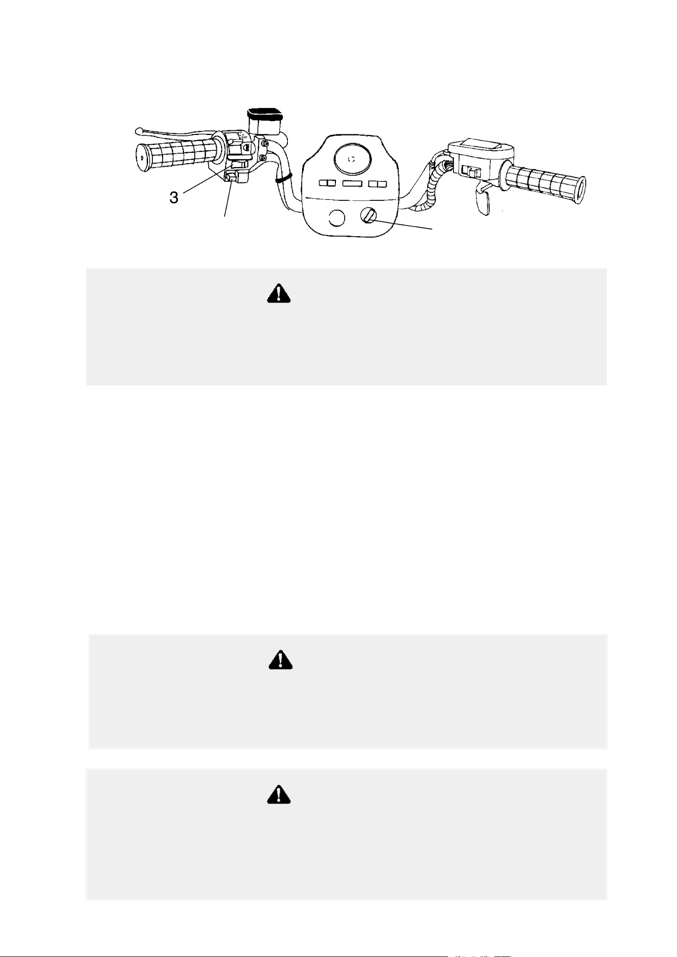
Electrical Switches
While operating in reverse, activating the override switch with the
throttle open can cause loss of control, resulting in severe injury
or death. Do not activate the override switch while the throttle is
open.
WARNING
Speedo Mode/Override Switch (1) (Reverse Speed Limiter) - This
switch, if pressed while in any gear but reverse, will change the display
mode of the speedometer (if equipped). To gain additional power
while operating in reverse, depress the override switch before opening
the throttle. NOTE: The override switch also allows activation of
Demand 4 Drive (All Wheel Drive) in reverse, if the Demand 4 Drive
switch is on.
Main Switch (2) - To start the engine, slide the stop switch to the
center RUN position and turn the main key switch clockwise past the
ON position. Release the key when the engine starts. NOTE: Turn off
the main switch to end all electrical power to the vehicle, including the
cooling fan and lights.
1
2
3
Leaving the keys in the ignition can lead to unauthorized use of
the vehicle resulting in serious injury or death. Always remove
the ignition key when the vehicle is not in use.
WARNING
A large key fob or key ring may contact the gas tank cap, causing
an interruption to the electrical system and an unexpected engine
shut-down during operation. This could result in serious injury or
death. Do not attach a large key fob or key ring to the main switch.
WARNING
38
FEATURES AND CONTROLS
Electrical Switches
Engine Stop Switch (3) - The engine will
not start or run when the switch is in the OFF
position. Its purpose is to provide the
operator with a quick means of engine
shutdown in case of an emergency. To stop
the engine, slide the stop switch either right
or left to the OFF position. NOTE: Turning
off the engine stop switch will shut off all electrical power to the
vehicle, with the exception of the cooling fan on some models. On
those models, use the main switch to shut off the power to the cooling
fan.
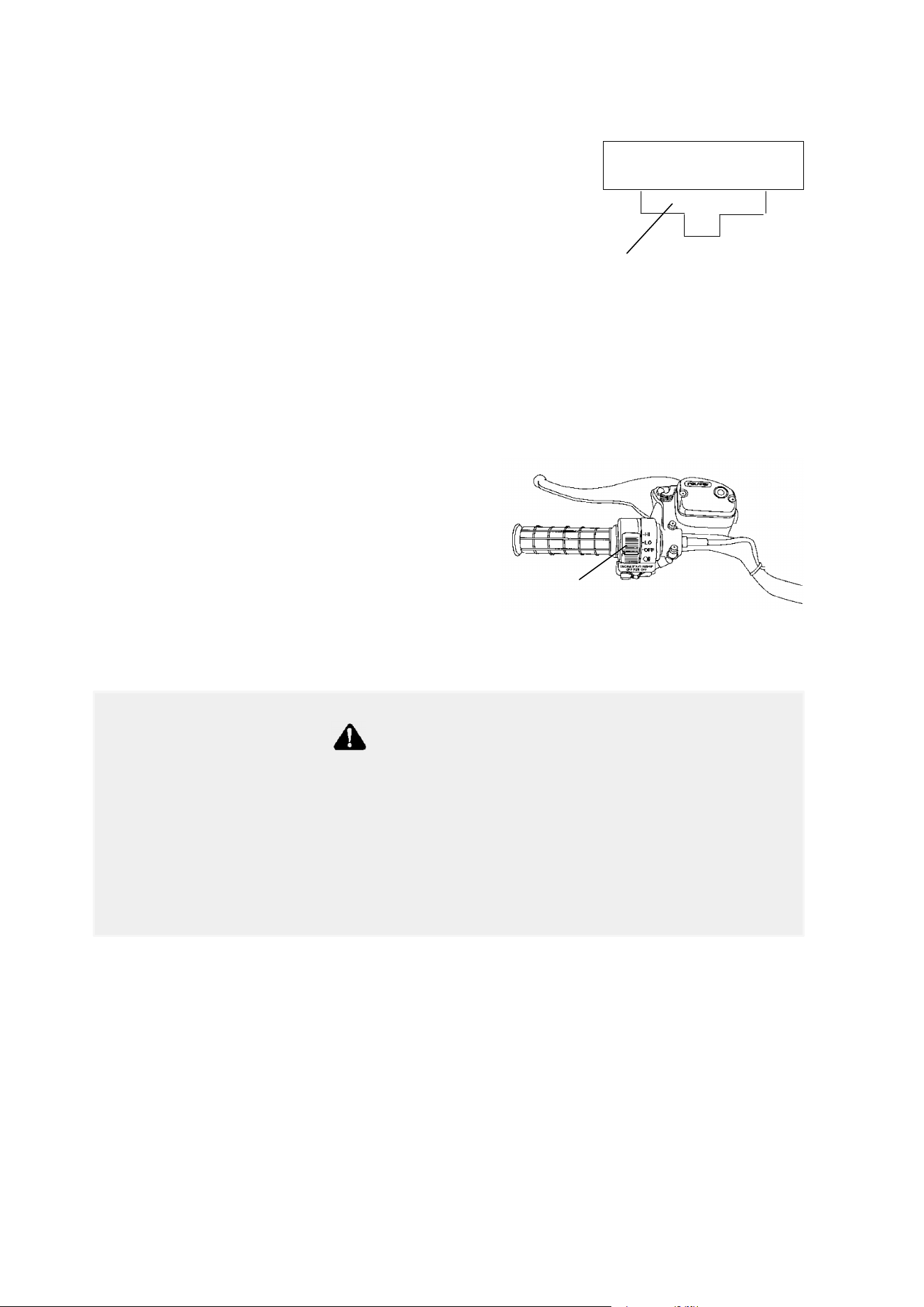
Light Switches
The light switch is located on the
left handlebar (1). It’s used to turn
the lights on and off and to switch
the lights from HI to LO on models
equipped with HI/LO beams.
NOTE: The lights won’t work
unless the key is in the ON position
and the shut-off switch is in the
RUN position.
RUN
OFFOFF
3
1
Operating the ATV on streets or roads, especially in darkness,
could result in an accident and serious injury or death.
Your ATV is not equipped with highway-approved lights. It’s
designed for and must be used for off-road use only. Use caution
and drive at reduced speeds in conditions of reduced visibility
such as fog, rain and darkness.
WARNING
39
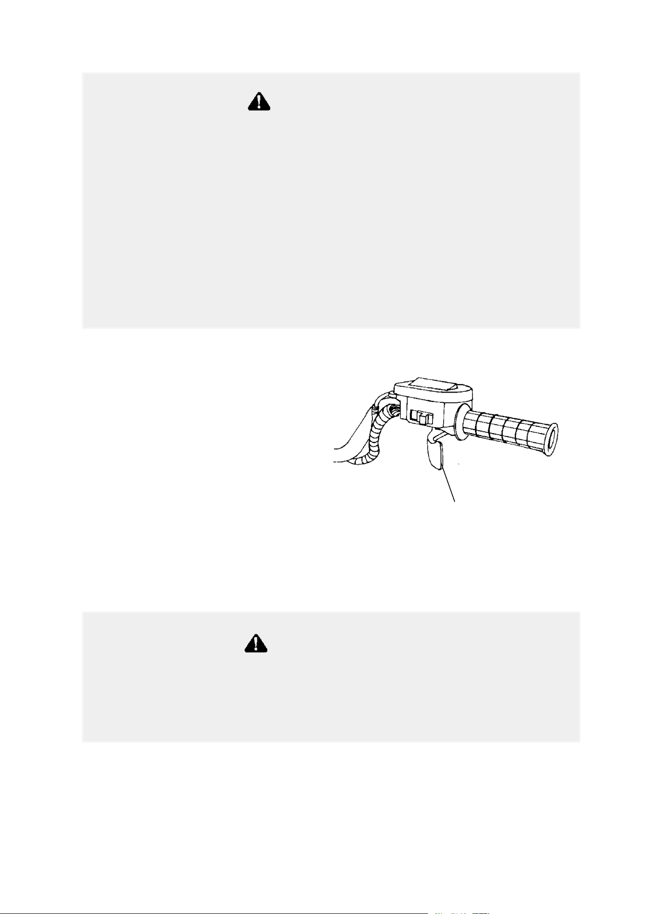
FEATURES AND CONTROLS
Throttle Lever
Engine speed and vehicle
movement are controlled by
pressing the throttle lever.
The throttle lever (1) is spring
loaded. Engine speed returns
to idle when the lever is
released.
This ATV is equipped with
Polaris Electronic Throttle Control
(ETC), which is designed to reduce the risk of a
frozen or stuck throttle. If the throttle cable should stick in an open
position when the operator releases the throttle lever, the engine will
stop, and power to the rear wheels will cease.
The Electronic Throttle Control (ETC) stops the engine in the
event of a throttle system malfunction and is provided for your
safety. Do not attempt to modify the ETC system or replace it
with any after market throttle mechanisms.
WARNING
Do not start or operate an ATV with sticking or improperly
operating throttle controls, which could cause an accident and
lead to severe injury or death.
Always contact your dealer for service repairs if throttle problems
arise.
Failure to check or maintain proper operation of the throttle
system can result in an accident if the throttle lever sticks during
operation.
Always check the lever for free movement and return before
starting the engine. Also check occasionally during operation.
WARNING
1
40
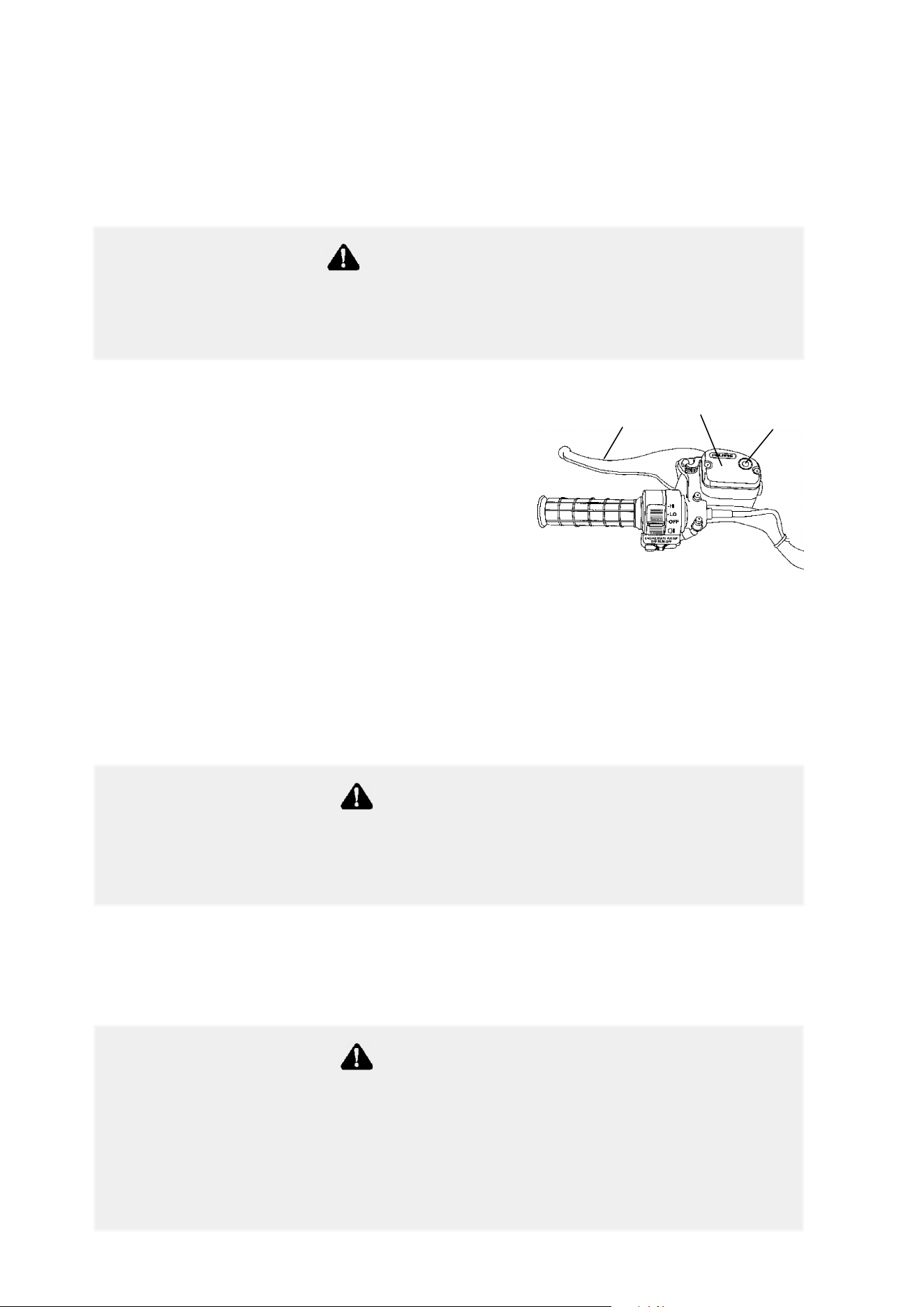
FEATURES AND CONTROLS
Brake Lever
The front and rear brakes are applied by squeezing the brake lever (1)
toward the handlebar. The front and rear brakes are hydraulically
activated disc type brakes that are activated by only one lever.
Always test brake lever travel and master
cylinder fluid level before riding.
When squeezed, the lever should feel
firm. Any sponginess would indicate a
possible fluid leak or low master
cylinder fluid level, which must be
corrected before riding. Contact your
dealer for proper diagnosis and repairs.
Brakes
Check the brake fluid level in the master cylinder before each use of
the ATV. The master cylinder (2) is located on the left handlebar.
The fluid level can be seen through an indicator window (3) on the top
of the master cylinder. This “eye” will appear dark when the fluid
level is full. When fluid needs to be added, the eye will be clear.
NOTE: When checking the fluid level, the ATV must be on level
ground with the handlebars straight. If the fluid level is low, add DOT
3 brake fluid only. DO NOT OVERFILL. See page 121 for the part
numbers of Polaris products.
Operating the ATV with a spongy brake lever can result in loss of
braking, which could cause an accident. Never operate the ATV
with a spongy-feeling brake lever.
WARNING
1
2
3
An over-full master cylinder may cause brake drag or brake
lock-up, which could result in serious injury or death. Maintain
brake fluid at the recommended level. Do not overfill.
WARNING
Never store or use a partial bottle of brake fluid. Brake fluid is
hygroscopic, meaning it rapidly absorbs moisture from the air. The
moisture causes the boiling temperature of the brake fluid to drop,
which can lead to early brake fade and the possibility of accident
or severe injury. After opening a bottle of brake fluid, always
discard any unused portion.
WARNING
41
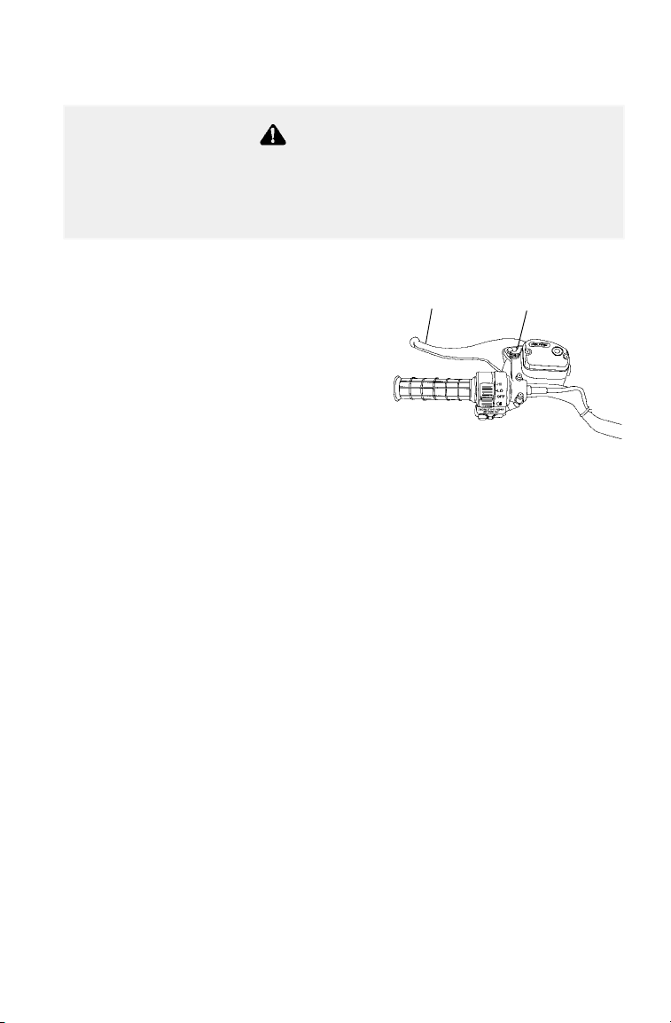
FEATURES AND CONTROLS
Parking Brake
Locking the Parking Brake
1. Squeeze and release the brake
lever (1) two or three times, then
squeeze and hold at full stroke.
2. Push the park brake lock (2)
forward to engage the brake.
Release the brake lever.
3. To release the parking brake lock,
squeeze and release the brake
lever. It will return to its unlocked
position.
Important Safeguards
S Always place the gear shifter in park before engaging the parking
brake.
S The parking brake may relax if left on for a long period of time. Al-
ways block the wheels to prevent rolling.
S Never depend on the parking brake alone if the ATV is parked on a
hill. Always block the wheels on the downhill side of the ATV to
prevent rolling. Another option is to park the ATV in a sidehill posi-
tion.
Operating the ATV while the parking brake is engaged could
result in an accident and serious injury or death. Always check
to be sure the parking brake is disengaged before operating.
WARNING
1
2
42
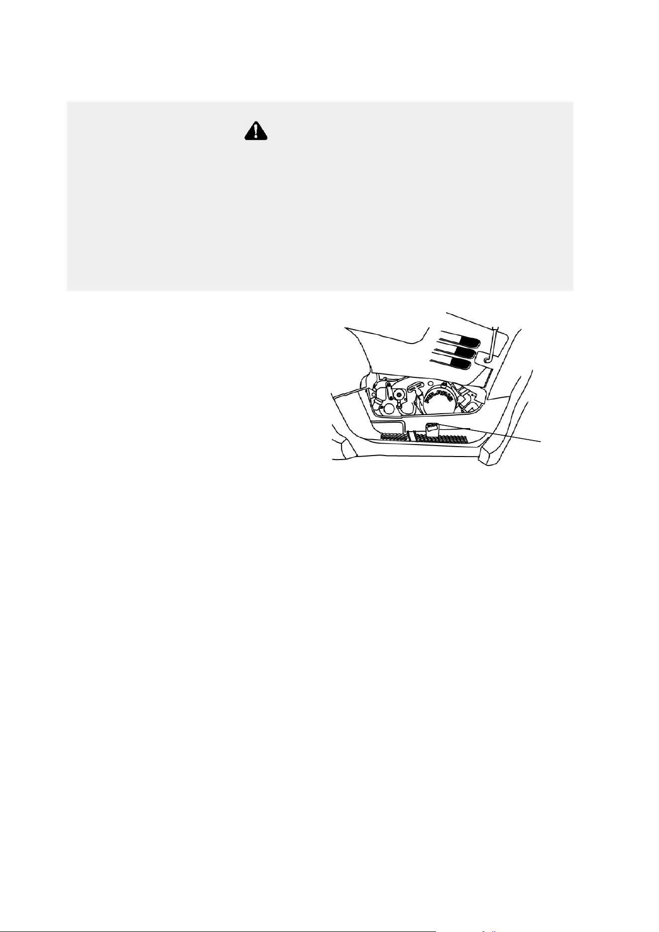
FEATURES AND CONTROLS
Auxiliary Brake
The auxiliary foot brake (1) is
located on the inside of the right
floor board and is operated by
the right foot. The auxiliary
brake serves as a backup to the
main brake system if the main
system becomes inoperative. It
activates the rear brakes only.
If the rear wheels slide while
using the auxiliary brake, reduce
brake pedal pressure to brake the rear wheels without skidding.
Check the brake fluid level frequently for the auxiliary brake system.
The reservoir is located under the seat or near the foot brake. Maintain
the fluid level between the maximum and minimum marks.
Aggressively applying the rear brake when backing down a hill
may cause rear tipover, which could result in serious injury or
death. If the rear brake is applied aggressively while moving
forward, the rear wheels may skid and slide sideways, causing
loss of control and serious injury or death.
Always use caution when applying the auxiliary foot brake. Do not
apply the auxiliary foot brake aggressively.
WARNING
1
43
FEATURES AND CONTROLS
Choke
The choke assists in starting a cold engine. Refer to the engine starting
procedure on page 55 for correct choke and throttle settings during
starting.
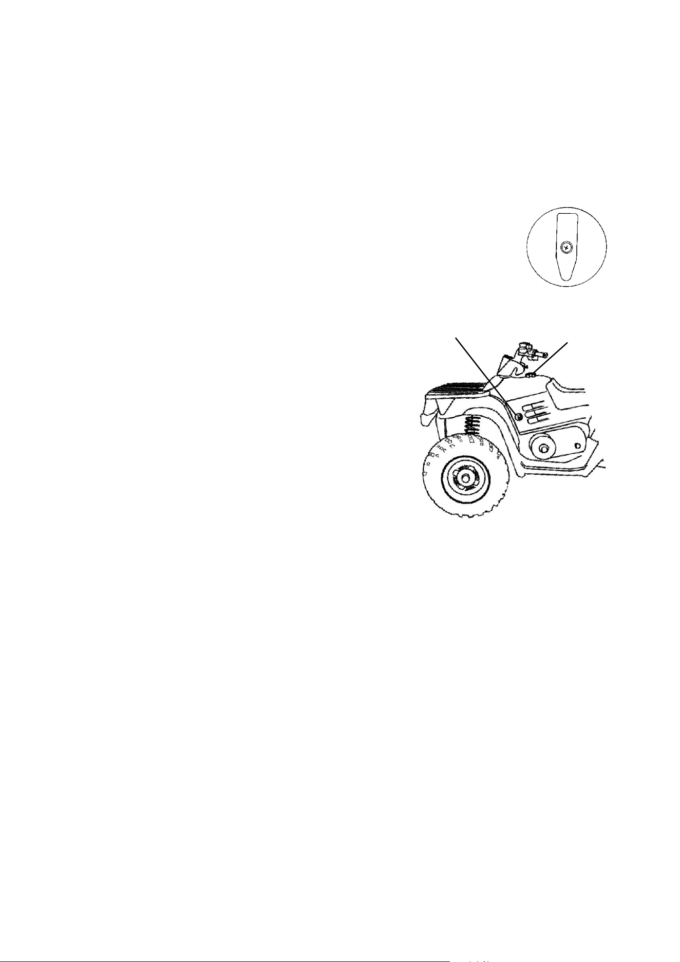
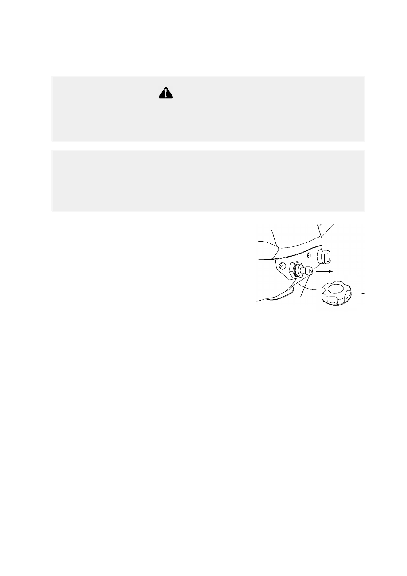
Fuel Valve
The fuel valve (1) is located on the left side
panel. It has three positions:
OFF: For vehicle storage and when transporting.
ON: For normal operation.
RES: For reserve supply if main
supply is exhausted.
NOTE: There’s about a 7 to 10 mile
(11.2 to 16 km) range on reserve gas.
Always refill the gas tank as soon as
possible after using the reserve supply.
Always return valve to the ON
position after refueling.
Fuel Tank
The fuel tank filler cap (2) is located
directly below the handlebar. Use
either leaded or unleaded gasoline with
a minimum pump octane number of
87=(R+ M/2) octane.
Fuel Filter
The in-line fuel filter should be replaced by your dealer after every 100
hours of operation, or annually. Do not attempt to clean the fuel filter.
RES
ON
OFF
2
1

44
FEATURES AND CONTROLS
Fuel Safety
Gasoline is highly flammable and explosive under certain
conditions.
S
Always exercise extreme caution whenever handling gasoline.
S
Always refuel with the engine stopped, and outdoors or in a
well ventilated area.
S Never fill a gas container while it’s in the cargo box. Static
electricity between the box and container could cause a spark.
S
Do not smoke or allow open flames or sparks in or near the
area where refueling is performed or where gasoline is stored.
S
Do not overfill the tank. Do not fill the tank neck.
S
If gasoline spills on your skin or clothing, immediately wash it
off with soap and water and change clothing.
S
Never start the engine or let it run in an enclosed area. Engine
exhaust fumes are poisonous and can cause loss of con-
sciousness or death in a short time.
S
Turn the fuel valve off whenever the ATV is stored or parked.
The engine exhaust from this product contains chemicals known
to cause cancer, birth defects or other reproductive harm.
Operate this vehicle only outdoors or in well-ventilated areas.
WARNING
WARNING

45
FEATURES AND CONTROLS
Automatic Transmission Gear Selector
The transmission gear selector (1)
is located on the right side of the
vehicle.
H: High Gear
L: Low Gear
N: Neutral
R: Reverse
P: Park
To shift into HIGH or PARK, you
must first apply the auxiliary brake
to activate the high/park lock-out mechanism. When shifting out of
HIGH or PARK, it’s not necessary to apply the brake.
Whenever the ATV is left unattended, always place the transmission in
park and lock the parking brake.
Maintaining shift linkage adjustment is important to assure proper
transmission function. See your dealer if you experience any shifting
problems.
Belt Life
To extend belt life, use low forward gear in heavy pulling situations and
when operating at less than seven miles per hour for extended periods of
time.
If towing the vehicle is necessary, shift the transmission into neutral for
better mobility and to prevent damage to the belt.
1
H
N
P
L
R
Shifting gears with the engine speed above idle or while the
vehicle is moving could cause transmission damage. To change
gears, stop the vehicle, and with the engine idling, move the
lever to the desired gear. Apply the auxiliary brake before
attempting to shift into high gear or park.
CAUTION

46
FEATURES AND CONTROLS
Recoil Starter
If the battery is weak and cannot
start the engine, use of the recoil
starter (1) will allow vehicle
operation until repairs can be
made. The recoil starter is located
on the right side of the machine.
Polaris 4-cycle engines are
equipped with automatic
decompressors. This makes recoil
starting possible by allowing
compression to “leak” at cranking
speeds. The decompressor senses when the engine is spinning fast
enough to start and restores compression for starting.
1. Position the vehicle on a level surface, place the transmission in
park and lock the parking brake (see page 41).
2. Grasp the recoil starter rope handle tightly and pull slightly until
the starter mechanism engages.
3. Pull the rope abruptly to start the engine.
1
Extending the starter rope too far will cause damage to the recoil
assembly. Do not extend the starter rope so far that it stops.
If the starter rope handle is not seated properly, water may enter
the recoil housing and damage components. Make sure the
handle is fully seated on the recoil housing, especially when
traveling in wet areas.
CAUTION

47
FEATURES AND CONTROLS
All Wheel Drive (AWD) System
Polaris 4 wheel drive ATVs
are equipped with a unique,
Polaris exclusive, Demand 4
Drive (AWD) system
activated by a switch (1) on
the right handlebar. When
the switch is on 2x4 (center
position), the ATV is in two
wheel drive at all times and the differential is locked. When the switch
is on AWD (left position), the ATV is in Demand 4 Drive and the
differential is locked. When the switch is on TURF (right position), the
differential is open, allowing the inside wheel to rotate independently
from the outside wheel during turns. Use the TURF mode to help
avoid causing damage to lawns and similar ground surfaces.
When in AWD, the front gearcase will automatically engage any time
the rear wheels lose traction. When the rear wheels regain traction, the
front gearcase will automatically disengage.
NOTE: The override switch allows activation of Demand 4 Drive
(AWD) in reverse if the Demand 4 Drive switch is on. See page 37.
There is no limit to the length of time the vehicle may remain in
Demand 4 Drive.
Engaging the Front Gearcase
The Demand 4 Drive switch may be turned on or off while the vehicle
is moving. Initially, the vehicle’s electronic system will not enable the
AWD until the engine RPM is below 3100. Once enabled, the AWD
remains enabled until the AWD switch is turned off. If the switch is
turned off while the front gearcase is moving, it will not disengage
until the rear wheels regain traction.
Engage the Demand 4 Drive switch before getting into conditions
where front wheel drive may be needed. If the rear wheels are
spinning, release the throttle before switching to Demand 4 Drive.
1
Switching to AWD (or from TURF to 2x4) while the rear wheels
are spinning may cause severe drive shaft and gearcase damage.
Always switch to AWD (or to TURF from 2x4) while the rear
wheels have traction or are at rest.
CAUTION
48
FEATURES AND CONTROLS
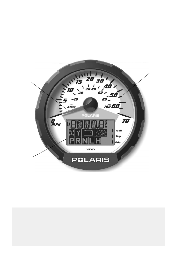
Instrument Cluster
Your ATV is equipped with an instrument cluster that senses vehicle
speed from the right front wheel. The instrument cluster measures
distance in miles as well as hours of operation. It also includes a
reverse speed limiter function that limits the ATV’s speed to
approximately 7-9 mph. Refer to page 37 for additional information.
1. Rider Information Center
2. Speedometer needle - in addition to showing vehicle speed, the
needle flashes when a warning condition exists.
3. Speedometer
2
3
1
CAUTION
To prevent damage, wash the ATV by hand or with a garden hose
using mild soap. Do not use alcohol to clean the instrument
cluster. Immediately clean off any gasoline that splashes on the
instrument cluster.
49
FEATURES AND CONTROLS
Instrument Cluster
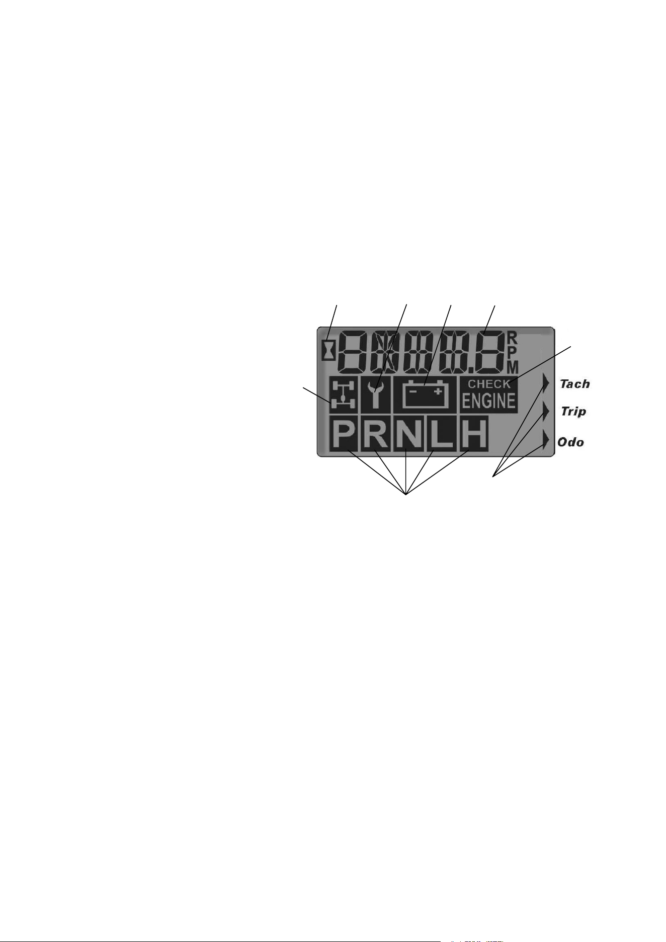
Rider Information Center
The rider information center is located in the instrument cluster. All
segments will light up for 2.5 seconds at start-up.
NOTE: If the instrument cluster fails to illuminate, a battery
over-voltage may have occurred and the instrument cluster may have
shut off to protect the electrical system. If this occurs, take the ATV to
your Polaris dealer for proper diagnosis.
1. Gear Indicator - As the shift lever is moved, this indicator shows
the gear the transmission is in:
H = High Range
L = Low Range
N = Neutral
R = Reverse
P = Park (if equipped)
2. AWD Indicator - This
indicator illuminates
when the electrical
portion of the AWD
system is enabled.
3. Engine Hour Display Indicator
4. Service Interval/Diagnostic Mode Indicator
5. Low Battery and Over Voltage - This warning usually indicates
that the ATV is being operated at an RPM too low to keep the
battery charged. A low battery warning may also occur under normal
operation if the machine is at idle and high electrical load (lights,
cooling fan, accessories) is applied. Driving at a higher RPM or
connecting a battery charger will usually clear the warning.
6. Odometer/Tachometer/Tripmeter/ Hour Meter
7. Check Engine Warning Indicator - The word HOT will display
alphanumerically when the engine is overheating. Do not continue
to operate the ATV is this warning appears or serious engine
damage could result.
8. Mode Indicator
7
5
4
3
1
6
2
8

50
FEATURES AND CONTROLS
Instrument Cluster
Rider Information Center
The rider information center has 4 standard modes:
Mode 1 - Odometer
Mode 2 - Tripmeter
Mode 3 - Total Service Hours
Mode 4 - Tachometer
The reverse override button on the left handlebar is also the mode
button. NOTE: If using the mode button to program the rider
information center, or to toggle through the options, the machine
cannot be in reverse.
Mode 1 - Odometer
The odometer records the miles traveled by the ATV.
Mode 2 -Trip Meter
The trip meter records the miles traveled by the ATV on each trip if it’s
reset before each trip. To reset the trip meter, select the trip meter
mode. Press and hold the mode button (override button) until the total
changes to 0 . NOTE: In the Rider Information Center, the trip meter
display contains a decimal point, but the odometer displays without a
decimal point.
Mode 3 - Hour Meter
This mode logs the total hours the engine has been in operation.
Mode 4 - Tachometer
The engine RPM is displayed digitally. NOTE: Small fluctuations in
the RPM from day to day may be normal because of changes in
humidity, temperature and elevation.

51
FEATURES AND CONTROLS
Instrument Cluster
Rider Information Center
Diagnostic Mode
The diagnostic mode is for informational purposes only. Please return
your ATV to your dealer for all major repairs.
As long as the gauge is in the diagnostic mode, the wrench icon will
remain lit.
To leave the diagnostic mode, either shift the machine out of neutral or
turn the key switch off and on. NOTE: Any movement of the tires
will also take the machine out of the diagnostic mode.
To enter the diagnostics mode:
1. Turn the key switch off and wait 10 seconds.
2. Set the parking brake and shift the transmission into neutral.
3. Hold the mode/reverse override button and turn the key switch on.
4. Release the switch as soon as the display is activated.
The initial screen display refers to the software version installed in
your ATV. This information is displayed briefly.
Use the mode/reverse override button to toggle through the diagnostic
screens.
Screen 1: Battery voltage
Screen 2: Tachometer
Screen 3: AWD diagnostic
This gauge indicates whether or not current is flowing through the
AWD coil (only on models with switchable AWD).
Screen 4: Gear circuit diagnostic
This screen displays the resistance value (in ohms) being read at the
gear switch input of the gauge.

52
FEATURES AND CONTROLS
Instrument Cluster
Rider Information Center
Diagnostic Mode
Screen 5: Programmable service interval
The purpose of the programmable service interval is to provide the
consumer and dealer with a convenient reminder for routine
maintenance. When your vehicle leaves the factory, this feature is set at
50 hours. You must enable the programmable service interval before it
can be used.
Once the service interval mode is set with the hours when service is
due, the hours of actual engine operation are subtracted from the set
hours until 0 is reached. When the counter reaches 0, the wrench icon
will flash quickly for 5 seconds each time the vehicle is started as a
reminder that the periodic maintenance is due.
To set the hours, press and hold the mode/override button until the
wrench icon flashes. When it begins to flash, release the button. The
setting will increase by one hour each time the button is pressed.
Pressing and holding the button will allow the numbers to escalate
much faster. When the desired time increment is displayed, release the
button and wait for the wrench to stop flashing. When the wrench
stops blinking, your service hours are set. NOTE: If you scroll past
the intended number, hold the button down until the count turns over to
0. You can then reset the number.
If the service interval is enabled on your ATV and you wish to turn it
off, toggle to the service interval mode. Press and hold the mode
button for approximately 7 seconds until the word OFF appears in the
Rider Information Center.
Screen 6: Miles/Kilometers toggle
The display in the tripmeter and odometer can be changed to display
either kilometers or miles. The current display mode will be shown as
KM or MP. To change, hold in the mode button until the letters flash,
then press and release the button once. When the display stops
flashing, the mode has been set.
53
OPERATION
Break-In Period
The break-in period for your new Polaris ATV is defined as the first ten
hours of operation, or the time it takes to use the first two full tanks of
gasoline. No single action on your part is as important as following
the procedures for a proper break-in. Careful treatment of a new
engine will result in more efficient performance and longer life for the
engine. Perform the following procedures carefully.
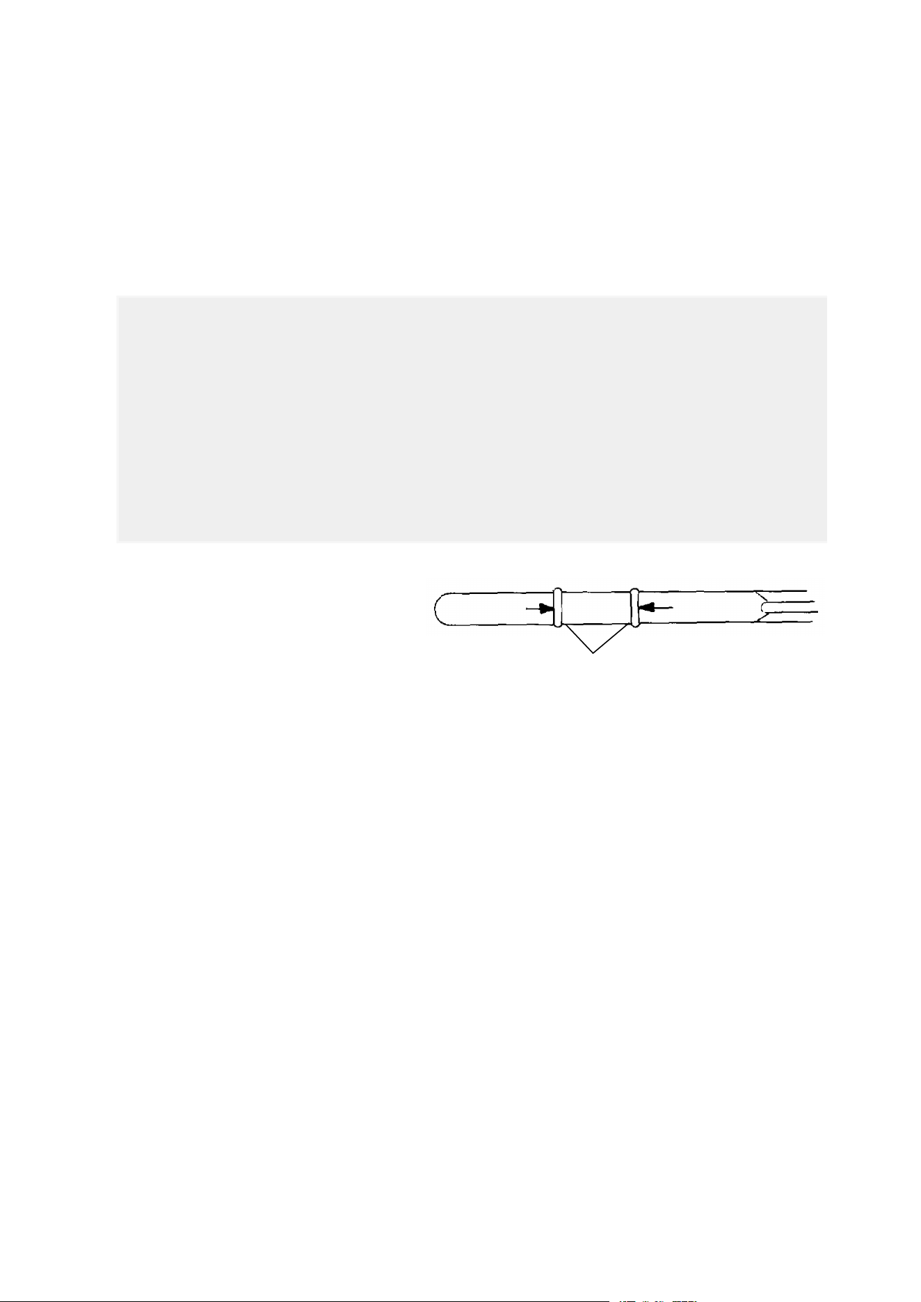
1. Fill the fuel tank with
gasoline. See page 43.
2. Check the oil level on
the dipstick. See page
82. Add Polaris
Premium 4 Synthetic Oil if necessary to maintain the oil level in
the normal (safe) operating range (1).
3. Drive slowly at first. Select an open area that allows room to
familiarize yourself with vehicle operation and handling.
4. Vary throttle positions. Do not operate at sustained idle.
5. Perform regular checks on fluid levels, controls and areas outlined
on the daily pre-ride inspection checklist. See page 54.
6. Pull only light loads.
7. During the break-in period, change both the oil and the filter at 20
hours or 200 miles.
CAUTION
Excessive heat build-up during the first three hours of operation
will damage close-fitted engine parts. Do not operate at full
throttle or high speeds for extended periods during the first three
hours of use.
Use of any oils other than those recommended by Polaris may
cause serious engine damage. We recommend the use of
Polaris Premium 4 Synthetic Oil for your 4-cycle engine.
ADD 8 OZ. NORMAL FULL
1

54
OPERATION
Pre-Ride Inspection
Use the following checklist to verify that your vehicle is in proper
working condition before each use.
Item/Inspection Procedure
1. Tires - Check condition and pressures.
2. Fuel and oil tanks - Fill both tanks to their proper levels.
3. All brakes - Check operation, adjustment and fluid level (includes
auxiliary brake).
4. Throttle - Check for free operation and closing.
5. Headlight/Taillight/Brakelight - Check operation of all indicator
lights and switches.
6. Engine stop switch - Check for proper function.
7. Wheels - Check for tightness of wheel nuts and axle nuts; check
that axle nuts are secured by cotter pins.
8. Air cleaner element - Check for dirt; clean or replace.
9. Steering - Check for free operation, noting any unusual looseness
in any area.
10. Loose parts - Visually inspect vehicle for any damaged components
or loose nuts/bolts or fasteners.
11. Riding gear - Wear a helmet, goggles and protective clothing.
12. Engine coolant - Check for proper level at the recovery bottle if
equipped.
If a proper inspection is not done before each use, severe
injury or death could result. Always inspect the vehicle before
each use to ensure it’s in proper operating condition.
WARNING
55
OPERATION
Starting the Engine
Starting a Cold Engine
1. Place the transmission in park and
lock the parking brake.
2. Turn the fuel tank valve on.
3. Sit on the vehicle.
4. Pull the choke knob out until it
stops (1).
NOTE: The variable choke is fully
on when the knob is pulled
completely out. The choke is off
when the knob is pushed completely in. The choke can be adjusted
gradually, depending on how much choke is needed for starting. Be
sure the choke is off during operation, as excess fuel washing into the
engine oil will increase wear on engine components.
5. Turn the engine stop switch to RUN.
NOTE: Do not press the throttle while starting the engine.
6. Turn the ignition key past the ON position to engage the starter.
Activate the starter for a maximum of five seconds, releasing the
key when the vehicle starts. If the engine does not start, release the
starter and wait five seconds. Then activate the starter for another
five seconds. Repeat this procedure until the engine starts.
7. If the engine slows or stops, position the choke knob half way in to
allow proper engine warm up.
8. Vary the engine RPM slightly with the throttle to aid in warm-up.
When the engine idles smoothly, push the choke all the way in.
Engine exhaust contains poisonous carbon monoxide and can
cause loss of consciousness resulting in severe injury or death.
Never run an engine in an enclosed area.
WARNING
Operating the vehicle immediately after starting could cause
engine damage. Allow the engine to warm up for several minutes
before operating the vehicle.
CAUTION
1

56
OPERATION
Starting the Engine
Starting a Warm Engine
Warm engines do not normally require the use of the choke. Using the
choke can cause the spark plug to become wet fouled.
1. Position the vehicle on a level surface with the transmission in
park.
2. Lock the parking brake, turn the fuel tank valve to ON, sit on the
vehicle, and turn the engine stop switch to RUN.
3. If the engine has cooled to a point where it does not readily start,
intermittent use of the choke button (pulled half way out) may be
necessary.
4. If the engine is over-choked when warm, depress the throttle lever
fully while cranking to aid in starting.
5. Release the throttle lever immediately after the engine starts. If the
engine does not start and all conditions are favorable, change the
spark plug and try again.
Cold Weather Operation for 4-Cycle Engines
If the ATV is used year-round, check the oil level frequently. A rising
oil level could indicate the accumulation of water in the bottom of the
oil tank. Water in the bottom of the tank can lead to engine damage
and must be drained. Water accumulation increases as outside
temperature decreases.
See your Polaris dealer for engine heater kits, which provide quicker
warm-ups and easier starting in colder weather.

57
OPERATION
Hauling Cargo
Overloading the vehicle or carrying or towing cargo improperly
can alter vehicle handling and may cause loss of control or
brake instability. Always follow these precautions when hauling
cargo:
S Never exceed the stated load capacity for this vehicle.
S Reduce speed and allow a greater distance for braking.
S When operating over rough or hilly terrain, reduce speed and
cargo to maintain stable driving conditions.
S WEIGHT DISTRIBUTION in the cargo bed should be as far
forward and as low as possible. Carrying a high load raises
the center of gravity and creates a less stable operating con-
dition. Reduce load weight when cargo is high. When han-
dling off-centered loads that cannot be centered, secure the
load and operate with extra caution.
S ALL LOADS MUST BE SECURED BEFORE OPERATING.
Unsecured loads may shift and create unstable operating
conditions, which could result in loss of control of the vehicle.
Always be sure that the cargo bed is lowered and latched be-
fore moving the vehicle.
S EXTREME CAUTION MUST BE USED when operating with
loads extending beyond the rack or cargo bed. Stability and
maneuverability may be adversely affected, causing the ma-
chine to overturn.
S Carrying a load on only the front rack or cargo bed may cause
an imbalanced condition and increases the possibility of ve-
hicle overturn. Balance loads proportionally between the front
rack and cargo bed, but do not exceed the stated load capac-
ity.
S Use extreme caution when applying brakes with a loaded ve-
hicle. Avoid terrain or situations that may require backing
downhill.
S Always attach the tow load to the hitch point.
S The vehicle should never exceed 10 mph (16 kph) while tow-
ing a load on a level surface. Vehicle speed should never ex-
ceed 5 mph (8 kph) when towing loads in rough terrain, while
cornering, or while ascending or descending a hill.
S Do not obstruct the headlight when loading the front rack.
WARNING

58
OPERATION
Hauling Cargo
Load Distribution
Your ATV has been designed to carry or tow a certain amount of load.
Always read and understand the load distribution warnings listed on
the warning labels, and never exceed the specified weights.
Cargo weight should be mounted as low as possible. When operating
over rough or hilly terrain, reduce speed and cargo to maintain stable
driving conditions.
1. Always load the cargo box with the load as far forward as possible.
2. Always operate the vehicle with extreme caution whenever hauling
or towing loads. Balance, handling, and control may be affected.
3. Slow down.
4. The cargo box dump latch must be securely latched before loading
and operating. Unintentional box tilting will result if weight is
placed in the rear of the box and the latch is not secured.
Maximum Towing Capacities
Do not exceed the following maximum capacities when towing.
Maximum grade while trailer towing is 15°. Do not tow any trailer on
a grade steeper than 15°.
Towing Load
(Level Ground)
Vertical Hitch
Weight
ATP 330 4x4 1000 lbs. ( 454 kg) 100 lbs. (45.4 kg)
ATP 500 4x4 1225 lbs. ( 556 kg) 120 lbs. (54.4 kg)
Belt Life
Use low forward gear when hauling or towing heavy cargo to extend
belt life.

59
OPERATION
Hauling Cargo
Dumping Cargo
1. Select a level site to dump the cargo box. Do not attempt to dump
or unload the vehicle while parked on an incline.
2. Place the transmission in park and set the parking brake.
3. Dismount the vehicle.
4. Lower the tailgate.
5. Pull the cargo box release lever upward.
6. Lift the front of the cargo box and dump the cargo.
7. Lower the cargo box and make sure the release latch is secured.
8. Secure the tailgate.
WARNING
If cargo weight is placed toward the rear of the cargo box, the
load may dump unexpectedly and cause serious injury. When
loading cargo, always position the weight as far forward and as
low as possible.
WARNING
Operating with the cargo box in the raised position can cause
serious injury and damage to the vehicle. The cargo box could
close unexpectedly and injure the driver. The rear tires will also
catch the rear of the bed, damaging the vehicle and creating
hazardous driving conditions.
Never operate this vehicle with the cargo box in the raised
position.
60
OPERATION
Driving Safely
Driving Procedures
1. Sit upright with both feet on the footrests and both hands on the
handlebars.
2. Start the engine and allow it to warm up, then shift the transmission
into gear.
3. Check your surroundings and determine your path of travel.
4. Release the parking brake.
5. Slowly depress the throttle with your right thumb and begin driving.
Vehicle speed is controlled by the amount of throttle opening.
6. Drive slowly. Practice maneuvering and using the throttle and brakes
on level surfaces.
61
OPERATION
Driving Safely
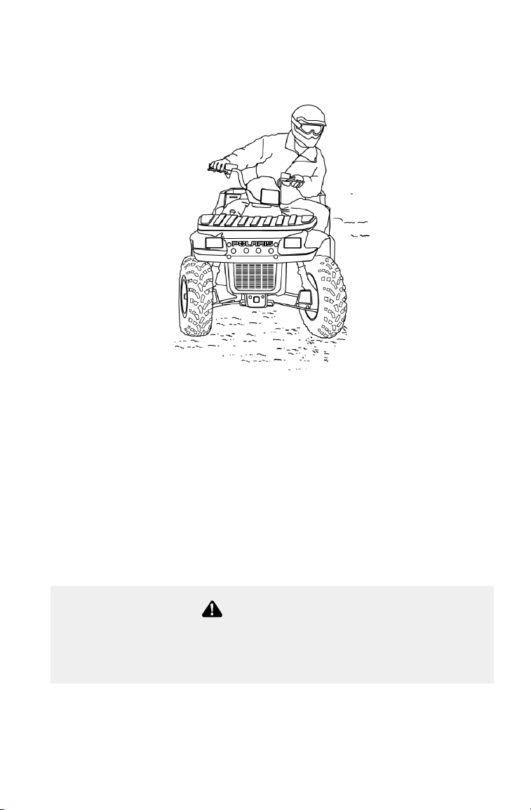
Making Turns
Your Polaris ATV is equipped with a rear differential that functions as
a solid rear axle, driving both rear wheels equally when the ATP is in
either 2x4 or 4x4 mode. This means that the wheel on the outside of a
turn must travel a greater distance than the inside wheel, causing the
inside tire to slip traction slightly.
To make a turn, steer in the direction of the turn, leaning your upper
body to the inside of the turn while supporting your weight on the
outer footrest. This technique alters the balance of traction between the
wheels, allowing the turn to be made smoothly. The same leaning
technique should be used for turning in reverse.
NOTE: Practice making turns at slow speeds before attempting to turn
at faster speeds.
WARNING
Turning at sharp angles or at excessive speeds can result in
vehicle overturn and lead to serious injury. Avoid turning at sharp
angles. Never make turns at high speeds.
62
OPERATION
Driving Safely
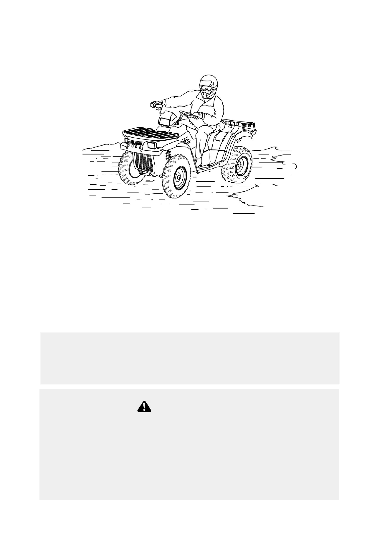
Driving on Slippery Surfaces
Whenever riding on slippery surfaces such as wet trails or loose gravel,
or during freezing weather, follow these precautions:
1. Slow down when entering slippery areas.
2. Maintain a high level of alertness, reading the trail and avoiding
quick, sharp turns which can cause skids.
3. Correct a skid by turning the handlebars in the direction of the skid
and shifting your body weight forward.
4. Driving with Demand 4 Drive (All Wheel Drive) engaged can assist in
controlling the vehicle in slippery areas.
Severe damage to drive train may occur if the AWD is engaged
while the wheels are spinning.
CAUTION
WARNING
Failure to exercise care when operating on slippery surfaces can
result in loss of tire traction and cause loss of control, accident,
and serious injury or death.
Never apply the brakes during a skid.
Do not operate on excessively slippery surfaces.
Always reduce speed and use additional caution.
63
OPERATION
Driving Safely
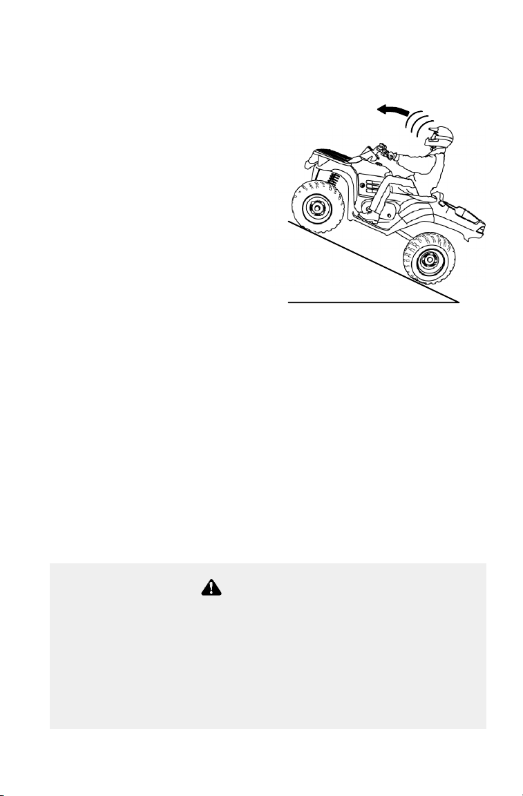
Driving Uphill
Whenever traveling uphill, follow these
precautions:
1. Always travel straight uphill.
2. Avoid steep hills (25_
maximum).
3. Keep both feet on the footrests.
4. Transfer your weight forward.
5. Proceed at a steady rate of
speed and throttle opening.
6. Remain alert and be
prepared to take emergency
action. This may include
quick dismounting of the
vehicle.
If all forward speed is lost:
Keep your weight uphill.
Apply the front brake (or the single lever brake, gradually). When fully
stopped, apply rear brake as well, then lock the park brake.
If the ATV begins rolling backwards:
Keep your weight uphill. Never apply engine power. Never apply the
rear brake while rolling backwards.
Apply the front brake (or single-lever brake, gradually). When fully
stopped, apply the rear brake as well, and then lock the parking brake.
Dismount on uphill side, or to either side if ATV is pointed straight
uphill. Turn the ATV around and remount, following the procedure
described on page 66.
25_ Maximum
WARNING
Braking and handling are greatly affected when operating in hilly
terrain. Improper procedure could cause loss of control or
overturn and result in serious injury or death.
Avoid climbing steep hills (25_ maximum).
Use extreme caution when operating on hills, and follow proper
operating procedures outlined in the owner’s manual.
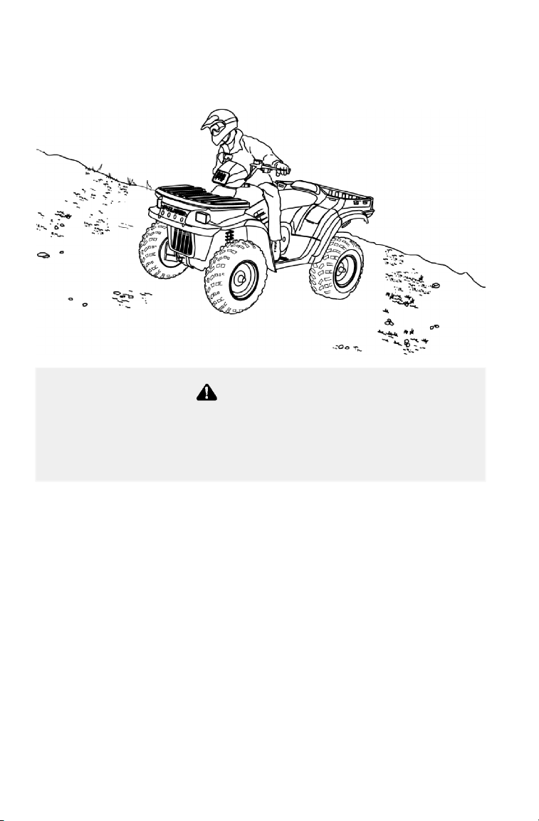
64
OPERATION
Driving Safely
Sidehilling
Sidehilling can be a dangerous type of driving and should be avoided if
at all possible. If you do enter into a situation where sidehilling is
necessary, follow these precautions:
1. Slow down.
2. Lean into the hill, transferring your upper body weight toward the hill
while keeping your feet on the footrests.
3. Steer slightly into the hill to maintain vehicle directions.
NOTE: If the vehicle begins to tip, quickly turn the front wheel
downhill, if possible, or dismount on the uphill side immediately!
Improperly crossing hills or turning on hills can result in loss of
control or vehicle overturn, resulting in severe injury or death.
Avoid crossing the side of a hill when possible. Follow proper
procedures as outlined in the owner’s manual.
WARNING
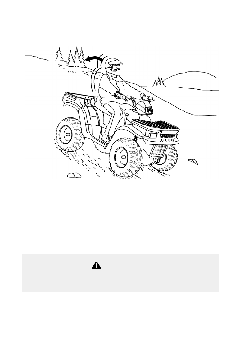
65
OPERATION
Driving Safely
Driving Downhill
Whenever descending a hill, follow these precautions:
1. Proceed directly downhill.
2. Transfer your weight to the rear of the vehicle.
3. Slow down.
4. Apply the brakes slightly to aid in slowing.
Familiarize yourself with operation of the auxiliary rear brake pedal for
additional braking in the event of normal service brake loss.
Excessive speed can cause loss of control and lead to serious
injury or death. Always operate slowly when traveling downhill.
WARNING
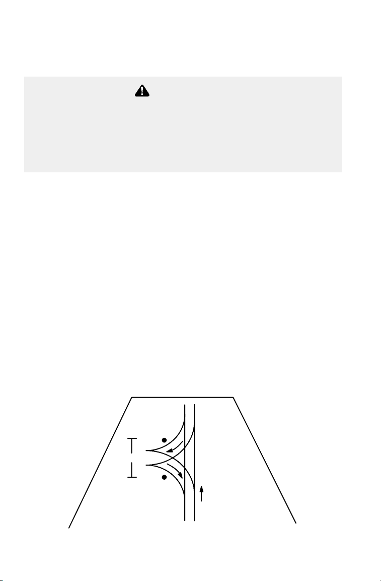
66
OPERATION
Driving Safely
Turning Around on a Hill
If the vehicle stalls while climbing a hill, never back it down the hill!
One maneuver that can be used when it’s necessary to turn around
while climbing a hill is the K-turn:
1. Stop and lock the parking brake while keeping body weight uphill.
2. Leave transmission in forward and shut off the engine.
3. Dismount on the uphill side of the vehicle, or on the left if the
vehicle is pointing straight uphill.
4. Staying uphill of the vehicle, turn the handlebars full left.
5. While holding the brake lever, release the parking brake lock and
slowly allow the vehicle to roll around to your right until it’s
pointing across the hill or slightly downward.
6. Lock the parking brake and remount the vehicle from the uphill
side, keeping body weight uphill.
7. Restart the engine with the transmission still in forward.
8. Release the parking brake and proceed slowly, controlling speed
with the brake, until the vehicle is on more level ground.
WARNING
Improper hill climbing procedures could cause loss of control or
overturn and result in serious injury or death.
Avoid climbing steep hills (25_ maximum).
Use extreme caution when operating on hills, and follow proper
operating procedures outlined in the owner’s manual.
8’
Uphill
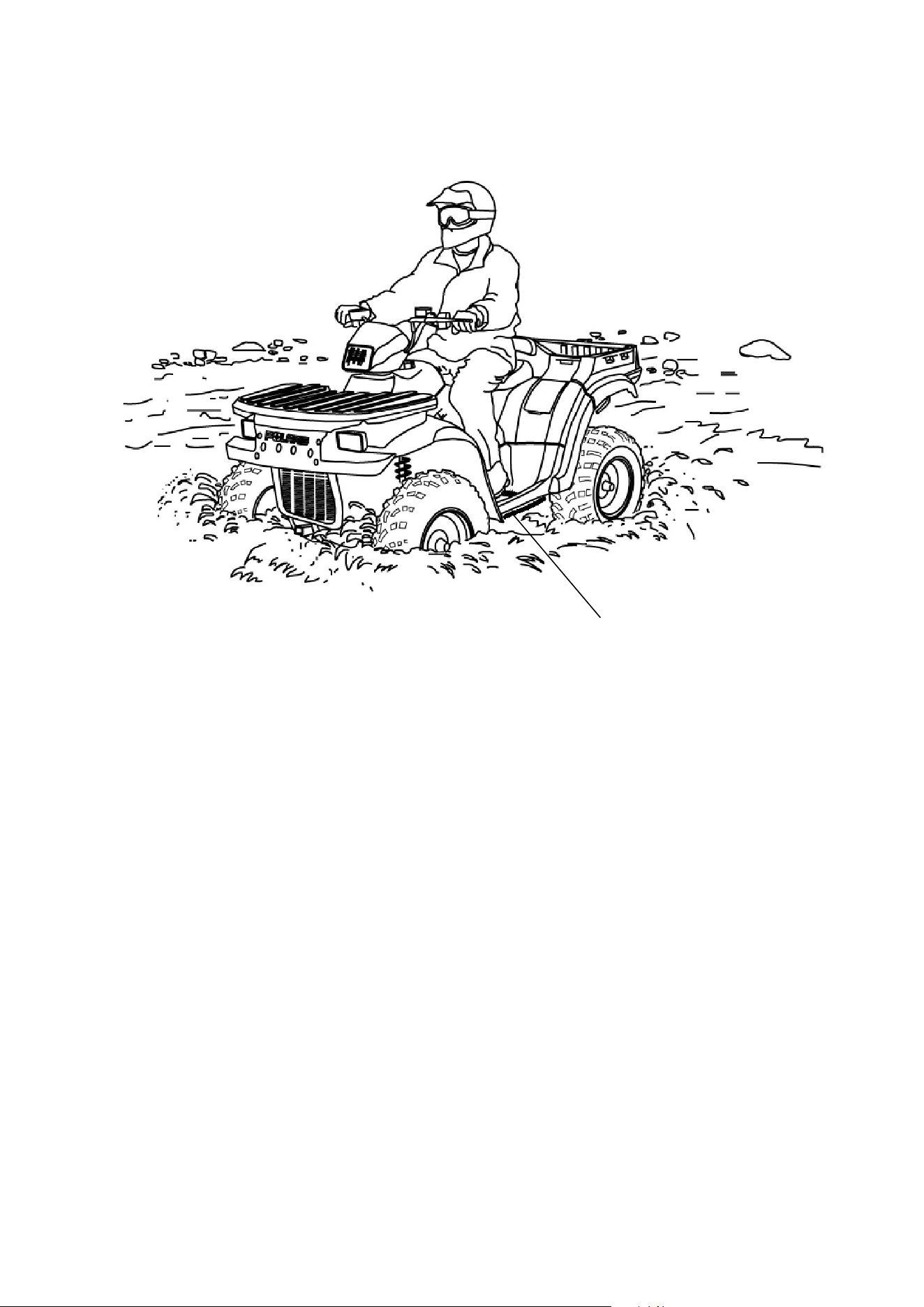
67
OPERATION
Driving Safely
Driving Through Water
Your ATV can operate through water with a maximum recommended
depth equal to the bottom of the footrests (1). Follow these procedures
when operating through water:
1. Determine water depths and current before crossing.
2. Choose a crossing where both banks have gradual inclines.
3. Proceed slowly, avoiding rocks and obstacles if possible.
4. After crossing, dry the brakes by applying light pressure to the
lever until braking action is normal.
NOTE: Avoid operating the vehicle through deep or fast-flowing
water. If you cannot avoid water that exceeds the recommended
maximum depth, go slowly, balance your weight carefully, avoid
sudden movements, and maintain a slow and steady forward motion.
Do not make sudden turns or stops, and do not make sudden throttle
changes.
1

68
OPERATION
Driving Safely
Driving Through Water
After running the vehicle in water, it’s critical to have it serviced as
outlined in the maintenance chart. See page 75. The following areas
need special attention: engine oil, transmission oil, front and rear
gearcases and all grease fittings. NOTE: If water has been ingested
into the PVT, follow the procedure on page 73 for drying out the PVT.
If your vehicle becomes immersed, and it’s impossible to take it to a
dealer before starting it, follow the steps described on page 110. Have
the vehicle serviced by your dealer promptly.
Major engine damage can result if the vehicle is not thoroughly
inspected after operation in water. Perform the services outlined
in the maintenance chart.
If your vehicle becomes immersed or is operated in water that
exceeds the footrest level, take it to your dealer for service
before starting the engine.
CAUTION
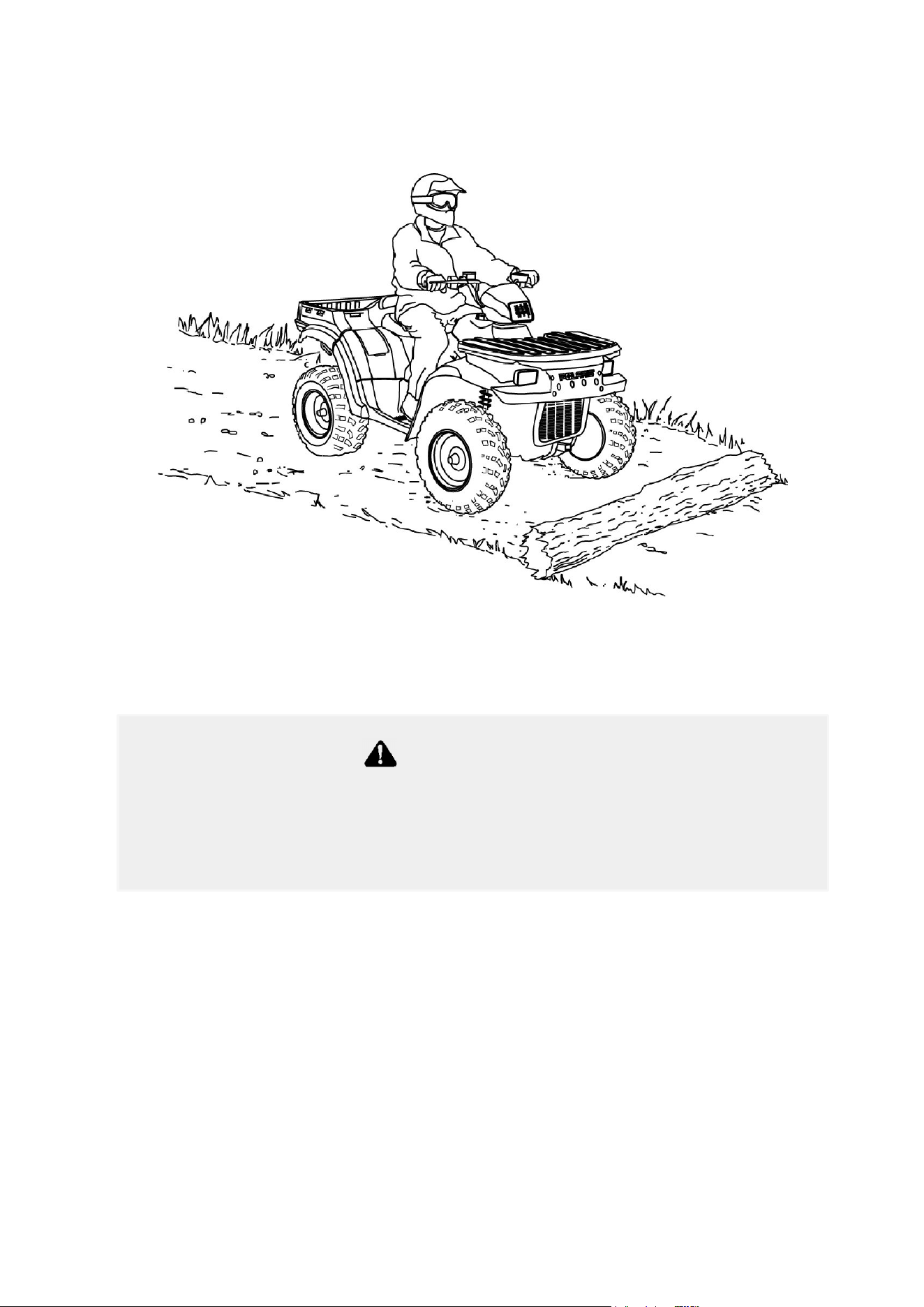
69
OPERATION
Driving Safely
Driving Over Obstacles
Be alert! Look ahead and learn to read the terrain. Be constantly alert
for hazards such as logs, rocks and low hanging branches.
Severe injury or death can result if your vehicle comes in contact
with a hidden obstacle. Not all obstacles are immediately visible.
Travel with caution in unfamiliar terrain.
WARNING
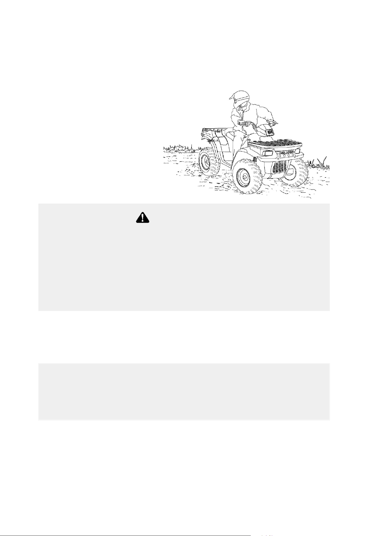
70
OPERATION
Driving Safely
Driving in Reverse
Follow these precautions when operating in reverse:
1. Always avoid backing
downhill.
2. Back slowly.
3. When in reverse,
apply the brakes
lightly for stopping.
4. Avoid turning at sharp
angles in reverse.
5. Never open the throttle
suddenly while backing.
NOTE: Most Polaris ATVs are equipped with a reverse speed limiter.
The override button should be used with caution as rearward vehicle
speed is greatly increased. Do not operate at wide open throttle. Open
the throttle just enough to maintain a desired speed.
WARNING
Failure to use caution when operating in reverse can result in
serious injury or death. Before shifting into reverse, always check
for obstacles or people behind the vehicle. When it’s safe to
proceed, back slowly.
Do not use the override switch unless additional power is required
for vehicle movement. Use with caution.
Avoid backing on inclines, and avoid turning at sharp angles.
Excessive throttle operation while in the speed limit mode may
cause fuel to build in the exhaust, resulting in engine popping
and/or engine damage.
CAUTION
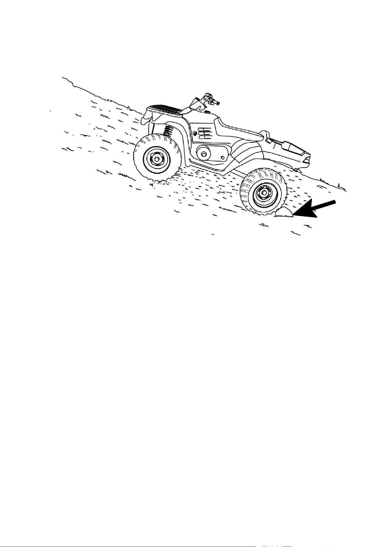
71
OPERATION
Driving Safely
Parking on an Incline
Avoid parking on an incline if possible. If it’s unavoidable, follow
these precautions:
1. Turn the engine off.
1. Place the transmission in park.
2. Set the parking brake.
3. Always block the rear wheels on the downhill side as shown in
illustration.
4. Shut off the fuel supply.

72
OPERATION
PVT System
The basic operation of the Polaris PVT system is dependent on engine
speed and vehicle torque requirements. As engine speed increases, the
force exerted on the movable drive sheave by the flyweights also
increases. This, in turn, increases the amount of “pinch” applied to the
drive belt. Similarly, if the engine speed decreases, the amount of
centrifugal force decreases, reducing the amount of belt “pinch.”
On Polaris ATVs, the approximate gear ratio difference between high
and low range is 1:2.25. This difference in gearing affects the operation
of the PVT, especially at speeds less than 7 MPH, due to the system’s
dependence on engine speed.
For example, when operating at a ground speed of 3 MPH in low
range, the engine speed would be around 3000 RPM. This is well
above the engagement speed of 1200 - 1400 RPM. However, in high
range at 3 MPH, the engine would be running at only 1500 RPM.
Whenever operating this close to the engagement speed, the engine
may be running at a speed too low to provide the “pinch” needed to
prevent belt slip. Belt slip is responsible for creating the excessive heat
that destroys belts and causes outer clutch covers to fail.
By switching to low range while operating at low ground speeds, the
air temperature in the clutch cover is reduced by almost 160 degrees.
Reducing the temperature inside the clutch cover extends the life of the
PVT components (belt, cover, etc.).
When To Use Low Range vs. High Range
Following is a guideline for when to use low range and high range.
Low Range
S When basic operation is at speeds less than 7 MPH
S For heavy pulling
S When operating in rough terrain (swamps, mountains, etc.) at low
ground speeds
High Range
S When basic operation is at speeds greater than 7 MPH
S When operating at high ground speeds

73
OPERATION
PVT System
PVT Drying
There may be some instances when water is accidently ingested into
the PVT system. Use the following instructions to dry it out before
operating:
1. Remove the drain plug and allow the water to drain. Replace the
drain plug.
2. Start the engine and shift the transmission into park. Apply varying
throttle for 10-15 seconds to expel the moisture and air-dry the belt
and clutches. Do not hold the throttle wide open for more than 10
seconds.
3. Allow the engine RPM to settle to idle speed, then shift the
transmission to the lowest available range.
4. Test for belt slippage. If the belt slips, repeat the process.
5. Take the vehicle to your dealer for service as soon as possible.
WARNING
Failure to comply with the instructions in this warning can result
in severe injury or death.
Do not modify any component of the PVT system. Doing so may
reduce its strength so that a failure may occur at a high speed.
The PVT system has been precision balanced. Any modification
will cause the system to be out of balance, creating vibration and
additional loads on components.
The PVT system rotates at high speeds, creating large amounts
of force on clutch components. Extensive engineering and
testing has been conducted to ensure the safety of this product.
However, as the owner, you have the following responsibilities to
make sure this system remains safe:
Always follow all recommended maintenance procedures. See
your dealer as outlined in the owner’s manual.
This PVT system is intended for use on Polaris products only. Do
not install it in any other product.
Always make sure the PVT housing is securely in place during
operation.
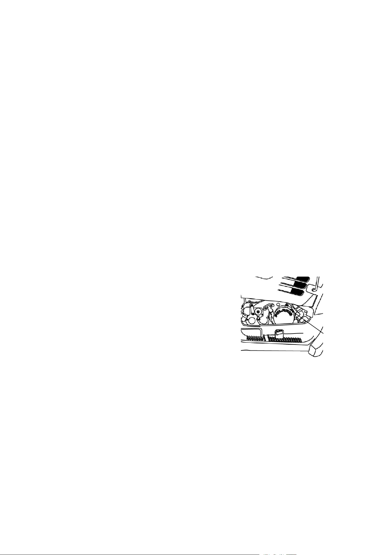
74
EMISSION CONTROL SYSTEMS
Noise Emission Control System
Do not modify the engine, intake or exhaust components, as doing so
may affect compliance with state and local noise level requirements.
Spark Arrestor
Your Polaris vehicle has a spark arrestor that was tested and approved
in accordance with the USDA Forest Service Standard 5100-1C.
Federal law requires that this spark arrestor be installed and functional
when the vehicle is operated on public lands.
Crankcase Emission Control System
This engine is equipped with a closed crankcase system. Blow-by
gases are forced back to the combustion chamber by the intake system.
The system does not allow the blow-by gases to enter the atmosphere.
Exhaust Emission Control System
The emissions from the exhaust of this vehicle are controlled by engine
design, including factory-set carburetion and ignition. The engine and
related components must be maintained at Polaris specifications to
achieve optimal performance.
Adjustment to engine idle is the only
adjustment Polaris recommends that the
operator perform. Any other adjustments
should be performed by an authorized
Polaris dealer.
The emissions label (1) is located on the
recoil cover.
1

75
MAINTENANCE AND LUBRICATION
Accessories
Polaris has a wide range of accessories available for your ATV.
Auxiliary power outlets provide 12V power for operating accessories
such as hand held spot lights. Accessory outlets are available for all
models. See your Polaris dealer for more information about
accessories.
Periodic Maintenance Schedule
Careful periodic maintenance will help keep your vehicle in the safest,
most reliable condition. Inspection, adjustment and lubrication of
important components are explained in the periodic maintenance
schedule.
Some ATVs are equipped with a speedometer that has a programmable
service interval mode. This important feature will help you determine
when maintenance service is due. See page 52 for instructions.
Maintenance intervals in the following charts are based upon average
riding conditions and an average vehicle speed of approximately 10
miles per hour. Vehicles subjected to severe use, such as operation in
wet or dusty areas, should be inspected and serviced more frequently.
Inspect, clean, lubricate, adjust and replace parts as necessary. When
inspection reveals the need for replacement parts, use genuine Polaris
parts available from your Polaris dealer.
NOTE: Service and adjustments are critical. If you’re not familiar
with safe service and adjustment procedures, have a qualified dealer
perform these operations.
Maintenance Chart Key
"
Perform these operations more often under severe use, such as in
dirty or wet conditions, to purge water or dirt contamination from
grease fittings and other critical components.
L Emission Control System Service (California - 4-Cycle)
NOTE: Some 4-Cycle models may have an additional California
-only emissions warranty.
J
Dealer service item.

76
MAINTENANCE AND LUBRICATION
Periodic Maintenance Schedule
Hours of operation are based on a 10 mph average. If service is due at
20 hours, the equivalent odometer reading would be 200 miles.
Perform all services at whichever reading is reached first.
Item Hours/
Miles
Frequency Remarks
Brake System Pre-Ride Pre-Ride Inspect
Auxiliary Brake Pre-Ride Pre-Ride Inspect
Tires Pre-Ride Pre-Ride Inspect
Wheels Pre-Ride Pre-Ride Inspect
Frame nuts, bolts,
fasteners
Pre-Ride Pre-Ride Inspect
Dump Box Latch Pre-Ride Pre-Ride Inspect; latch securely
"
L
Air filter,
Pre-cleaner
Pre-Ride Pre-Ride Inspect; clean
Coolant level Pre-Ride Pre-Ride Replace coolant every two
years
Fuel and oil tanks Pre-Ride Pre-Ride Fill to proper levels
Throttle Pre-Ride Pre-Ride Check operation
Lights Pre-Ride Pre-Ride Check operation
Engine stop switch Pre-Ride Pre-Ride Check operation
Steering Pre-Ride Pre-Ride Check for free operation
"
Air box sediment
tube
Pre-Ride Pre-Ride Drain deposits whenever
visible
Headlamp Pre-Ride Pre-Ride Check operation daily; ap-
ply Polaris dielectric grease
to connector when replaced
Improperly performing the procedures marked with a
J
could
result in component failure and lead to serious injury or death.
Have an authorized Polaris dealer perform these services.
WARNING

77
MAINTENANCE AND LUBRICATION
Periodic Maintenance Schedule
Item Hours/
Miles
Frequency Remarks
Taillight/brakelight Pre-Ride Pre-Ride Check operation daily; ap-
ply Polaris dielectric grease
to socket when replaced
"
L
Air filter,
main element
Weekly Weekly Inspect; replace as needed
"
Transmission oil
level
20 hrs Monthly Inspect monthly; change
annually
Battery 20 hrs Monthly Check terminals; clean.
"
L
Engine breather
filter
20 hrs Monthly Inspect; replace annually
and as needed
J
Brake pad wear 10 hrs Monthly Inspect periodically
"
Front and rear
gearcase oil
100 hrs Monthly Check monthly; change
annually
Engine cylinder
head and cylinder
base fasteners
25 hrs 3 months Inspect (re-torque required
at first service only)
"
General lubrication 50 hrs 3 months Lubricate all fittings, pivots,
cables, etc.
"
L
Engine oil level/oil
change
100 hrs /
1000
miles
6 months Check level daily; break-in
service at one month;
change oil more often in
cold weather
"
L
Oil Filter 100 hrs./
1000 mi.
6 months Replace with oil change
L
Engine breather
hose
100 hrs. 6 months Inspect
"
More often under severe use, such as dirty or wet conditions
L
Emission Control System Service (California)
J
Dealer service item

78
MAINTENANCE AND LUBRICATION
Periodic Maintenance Schedule
Item Hours/
Miles
Frequency Remarks
Carburetor float
bowl
50 hrs. 6 months Drain bowl periodically and
prior to storage
J
Throttle Cable/ETC
Switch
50 hrs. 6 months Inspect; adjust; lubricate;
replace if necessary
L
Choke (enricher)
cable
50 hrs. 6 months Inspect; adjust; lubricate;
replace if necessary
Coolant strength/
pressure test sys-
tem
100 hrs. 6 months Inspect strength seasonal-
ly; pressure test system
annually
Shift linkage 50 hrs. 6 months Inspect; adjust
J
Drive belt 50 hrs. 6 months Inspect; replace as needed
"
Steering 50 hrs. 6 months Inspect daily; lubricate
"
Front suspension 50 hrs. 6 months Inspect; lubricate; tighten
fasteners
"
Rear suspension 50 hrs. 6 months Inspect; tighten fasteners
L
Spark plug 100 hrs. 12 months Inspect; replace as needed
J
L
Ignition Timing 100 hrs. 12 months Inspect; adjust as needed
Improperly performing the procedures marked with a
J
could
result in component failure and lead to serious injury or death.
Have an authorized Polaris dealer perform these services.
WARNING

79
MAINTENANCE AND LUBRICATION
Periodic Maintenance Schedule
Item Hours/
Miles
Frequency Remarks
J
L
Fuel system 100 hrs. 12 months Check for leaks at tank
cap, lines, fuel valve, filter,
pump and carburetor; re-
place lines every two years
J
Fuel filter 100 hrs. 12 months Replace annually
Radiator (500) 100 hrs. 12 months Inspect; clean external sur-
face
Cooling system
hoses (500)
100 hrs. 12 months Inspect
"
Front gearcase 100 hrs. 12 months Change fluid annually
J
Clutches
(drive and driven)
100 hrs. 12 months Inspect; clean
Engine mounts 100 hrs. 12 months Inspect
J
L
Valve clearance 100 hrs. 12 months Inspect; adjust
J
Brake fluid 200 hrs. 24 months Change every two years
Spark arrestor 300 hrs. 36 months Clean out
"
Rear axle As required Inspect bearings if axle has
ingested water or if unusual
noises are present
L
Idle speed As required Adjust as needed
Recoil housing As required Drain moisture after
operating in water
J
Toe adjustment As required Periodic inspection; adjust
when parts are replaced
Headlight aim As required Adjust as needed
"
More often under severe use, such as dirty or wet conditions
L
Emission Control System Service (California)
J
Dealer service item

80
MAINTENANCE AND LUBRICATION
Lubrication Recommendations
NOTE: Hours are based on 10 mph average. If service is due at 20
hours, the equivalent odometer reading would be 200 miles. Perform
all services at whichever reading is reached first.
Lubrication Chart Key
"
More often under severe use, such as wet or dusty conditions
L
Polaris Premium All Season Grease or grease conforming to NLG
No. 2, such as Conoco Superlube M or Mobilegrease Special
F
Use Polaris Premium U-Joint Lube every 500 miles, before long
periods of storage, or after pressure washing or submerging
Item Lube Method Frequency
Engine Polaris Premium 4
Synthetic 0W40
Add to proper level on dip-
stick.
Check level daily.
Brakes DOT 3 fluid only Maintain level between fill
lines. See page 40.
As required; change
every two years or
200 hours
Transmission Polaris Premium
Synthetic gear
case lube
See Page 88. Check every 6
months/1000 miles.
Change annually or
at 100 hours
Front Gear-
case
Polaris Premium
Synthetic gear
case lube
See Page 89. Change annually or
at 100 hours
Front Prop
Shaft U-joints
F
Grease Grease fittings. Every 3 months or
50 hours
Front Prop
Shaft Yoke
F
Grease Grease fittings
(3 pumps maximum)
Every 3 months or
50 hours
Front Drive
Axle (U Joint)
F
Grease Locate grease fitting and
grease with grease gun.
Every 3 months or
50 hours
Ball Joint
"
L
Grease
Locate fitting on back side of
struts and grease with
grease gun.
Every 3 months or
50 hours

81
MAINTENANCE AND LUBRICATION
Periodic Maintenance Record
Use the following chart to record periodic maintenance.
Maintenance
Interval
Performed
Servicing
Date
Servicing
Dealer
or Person
Remarks
10 hrs.
20 hrs.
50 hrs.
100 hrs.
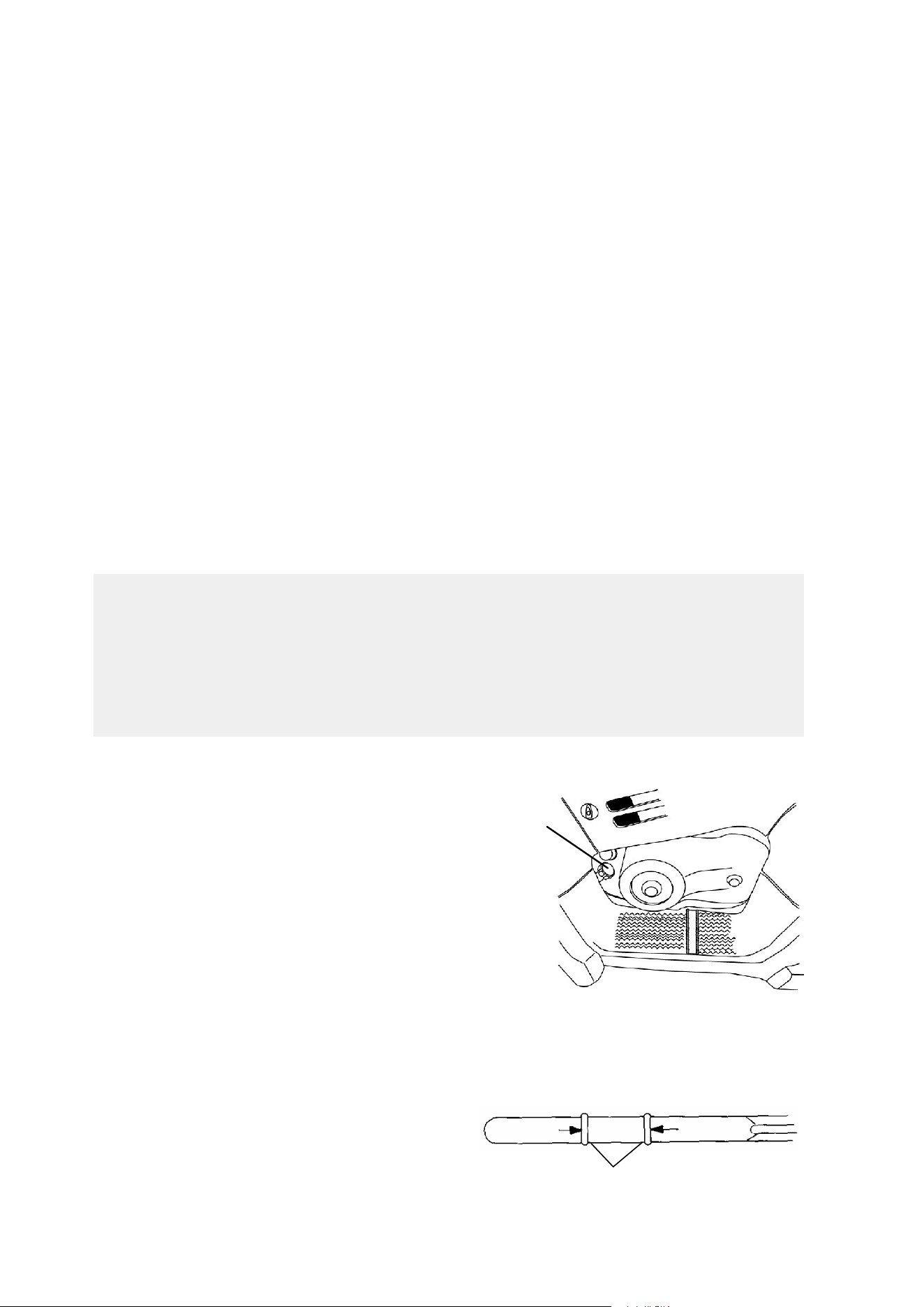
82
MAINTENANCE AND LUBRICATION
Lubrication Recommendations
Premium 4 Synthetic Oil
Polaris Premium 4 All Season Synthetic engine oil has been specially
formulated for use in Polaris 4-cycle engines. It’s a fully synthetic,
high performance, multi-viscosity oil designed to provide the ultimate
in lubrication performance and protection. NOTE: See page 121 for the
part numbers of Polaris products.
Premium 4 possesses unsurpassed film strength over the widest
possible temperature range. It resists viscosity and frictional
breakdown in ambient temperatures from -40° F. to 120° F. Its
exceptional frictional properties result in more efficient operation, more
power output and lower fuel consumption.
Although Polaris Premium 4 is the only oil recommended for use in
this engine, use of any API certified “SH” oil is allowable as long as
it’s 0W-40. Oil may need to be changed more frequently if Polaris
Premium 4 is not used. Follow the manufacturer’s recommendations
for ambient temperature operation.
Engine Oil Check
The oil tank is located on the left side
of the vehicle.
1. Position the machine on a level
surface.
2. Start the engine and let it idle for
20-30 seconds. Stop the engine.
3. Remove the dipstick (1) and wipe
it dry with a clean cloth.
4. Screw the dipstick completely in. NOTE: The dipstick must be
screwed completely in to keep the angle and depth of the stick
consistent.
5. Remove the dipstick and
read the oil level.
Maintain the oil level in
the normal operating
range (2). Do not overfill.
CAUTION
Mixing brands or using a non-recommended oil may cause serious
engine damage. We recommend the use of Polaris Premium 4 All
Season synthetic oil or API certified “SH” oil, 0W-40. Never
substitute or mix oil brands. Use only 0W-40.
1
ADD 8 OZ. NORMAL FULL
2

83
MAINTENANCE AND LUBRICATION
Lubrication Recommendations
Oil and Filter Change - ATP 500 4x4
The recommended oil change interval is 100 hours, 1000 miles, or
every six months, whichever comes first. Suggested break-in oil
change is at 20 hours, 200 miles, or one month, whichever comes first.
Severe use requires more frequent service. Severe use includes
continuous duty in dusty or wet conditions and cold weather operation.
Severe use cold weather operation is all operation below 10° F. and
operation between 10° F. and 30° F. when most trips are at a slow
speed. Always change the oil filter whenever changing oil.
1. Obtain the correct oil filter and an adequate supply of oil so the oil
and filter change can be completed without interruption.
2. Position the vehicle on a level surface. Clean the area around the
drain plug at the bottom of the oil tank and the bottom of the
engine.
3. Run the engine for two to three minutes, then turn it off.
CAUTION
If the ATV is left without oil in the system for extended periods, the
oil pump may lose its prime, which could result in engine damage.
Always replace the oil and filter within a few hours of draining the
oil. Do not allow the vehicle to be without oil overnight.
CAUTION
Hot oil can cause serious burns to skin. Do not allow hot oil to
come into contact with skin.
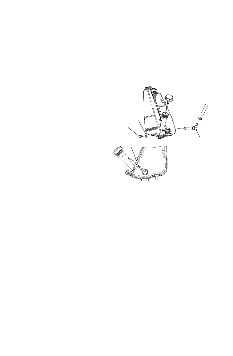
84
MAINTENANCE AND LUBRICATION
Lubrication Recommendations
Oil and Filter Change - ATP 500 4x4
4. Place a drain pan beneath the oil tank and remove the drain plug
(1). Allow the oil to drain completely.
5. Install a new sealing washer (2) on the oil drain plug. NOTE:
The sealing surfaces on the drain plug and the oil tank should be
clean and free of burrs, nicks or scratches.
6. Reinstall the drain plug
and torque to 14-17 ft.
lbs. (1.93-2.35 kg/m)
7. Disconnect the lower oil
delivery hose and remove
the screen fitting (3) from
the oil tank. Clean and
reinstall the fitting,
torquing to 25 ft. lbs.
Reattach the oil line.
NOTE: The fitting
threads must be sealed
with Loctitet PST 505 or
PTFE seal tape. The
fitting must also line up with
the mark (4) on the rear side of the oil tank.
1
2
3
4

85
MAINTENANCE AND LUBRICATION
Lubrication Recommendations
Oil and Filter Change - ATP 500 4x4
8. Place shop towels beneath
the oil filter. Using an oil
filter wrench, turn the filter
(1) counterclockwise and
remove.
9. Lubricate the gasket on the
new filter with a film of
new engine oil. Check to
make sure the gasket is in
good condition. Also make
sure the gasket from the old
filter is not still on the engine.
10. Install the new filter and tighten by hand 1/2 to 3/4 turn after
gasket contacts the engine.
11. Approximately one cup of engine oil will remain in the crankcase.
To drain, remove the drain plug on the lower right side of the
crankcase. NOTE: The sealing surfaces on the drain plug and
crankcase should be clean and free of burrs, nicks or scratches.
12. After draining, reinstall the drain plug.
13. Remove the dipstick (2) and add two quarts (1.9 l.) of Polaris
Premium 4 synthetic oil. Reinstall the dipstick. NOTE: If the
sump is not drained, add about 1 3/4 quarts initially.
14. Place the gear selector in park and set the parking brake.
15. Start the engine and let it idle for one to two minutes. Stop the
engine and inspect for leaks.
16. Recheck the oil level on the dipstick and add oil as necessary to
bring the level to the upper (full) mark on the dipstick.
17. Dispose of used filter and oil properly.
2
1

86
MAINTENANCE AND LUBRICATION
Lubrication Recommendations
Oil and Filter Change - ATP 330 4x4
1. Obtain the correct oil filter and an adequate supply of oil so the oil
and filter change can be completed without interruption.
2. Position the vehicle on a level surface.
3. Clean the area around the drain plug on the bottom of the engine
crankcase.
4. Run the engine for two to three minutes until warm. Stop the
engine.
5. Place a drain pan beneath the engine crankcase and remove the
drain plug.
6. Allow the oil to drain completely.
7. Install a new sealing washer on the drain plug. NOTE: The
sealing surfaces on the drain plug and crankcase should be clean
and free of burrs, nicks or scratches.
CAUTION
If the ATV is left without oil in the system for extended periods, the
oil pump may lose its prime, which could result in engine damage.
Always replace the oil and filter within a few hours of draining the
oil. Do not allow the vehicle to be without oil overnight.
Contact with hot oil may result in serious burns. Do not allow hot
oil to come into contact with skin.
CAUTION

87
MAINTENANCE AND LUBRICATION
Lubrication Recommendations
Oil and Filter Change - ATP 330 4x4
8. Reinstall the drain plug and torque to 14 ft. lbs. (19 Nm).
9. Place shop towels beneath the oil filter. Using an oil filter wrench,
turn the filter counterclockwise to remove.
10. Using a clean, dry cloth, clean the filter sealing surface on the
crankcase.
11. Lubricate the gasket on the new filter with a film of engine oil.
Check to make sure the gasket is in good condition.
12. Install the new filter and turn by hand until the filter gasket
contacts the sealing surface, then turn and additional 1/2 turn.
13. Remove the dipstick and fill the sump with 2 quarts (1.9 l) of
Polaris Premium 4 synthetic oil.
14. Place the gear selector in park and set the parking brake.
15. Start the engine and let it idle for one to two minutes. Stop the
engine and inspect for leaks.
16. Recheck the oil level and add oil as necessary to bring the level to
the upper mark on the dipstick.
17. Dispose of used filter and oil properly.
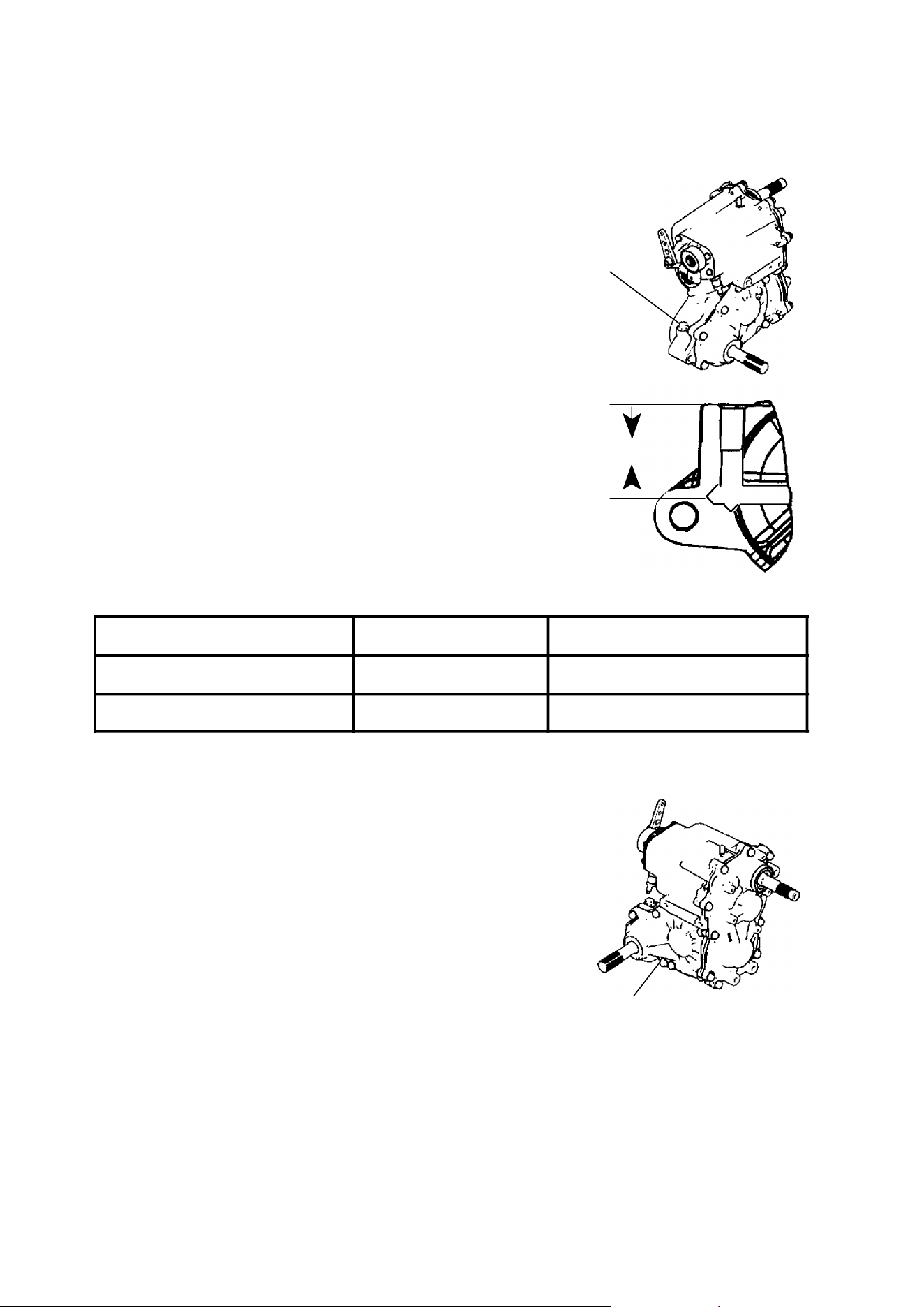
88
MAINTENANCE AND LUBRICATION
Lubrication Recommendations
Transmission Oil Check
The transmission lubricant level should be checked
every six months or 1000 miles (1600 km),
whichever comes first. Transmission oil should be
changed annually.
1. Position the ATV on a level surface,
remove the fill plug (1), and check the oil
level. NOTE: The transmission fill plug is
located on the right side of the machine,
behind the footwell.
2. Use the gearcase oil fill chart and the
following illustration to determine correct
fluid levels. NOTE: When adding oil, use
Polaris Premium Synthetic Gearcase
Lubricant. See page 121 for the part numbers
of Polaris products.
Gearcase Oil Fill Chart
Model Oil Level “A” Capacity
ATP 500 4x4 1 5/8″ 13.5 oz. (400 ml)
ATP 330 4x4 1 5/8″ 13.5 oz. (400 ml)
1. Remove the fill plug.
2. Remove the transmission drain plug (2)
located on the bottom left hand side and
drain the oil. Catch and discard used oil
properly.
3. Clean and reinstall the drain plug torque to
14 ft. lbs. (19 Nm).
4. Add the correct amount of Polaris
Premium Synthetic Gearcase Lubricant.
Refer the the gearcase oil fill chart for
proper oil levels.
5. Check for leaks.
1
A
2
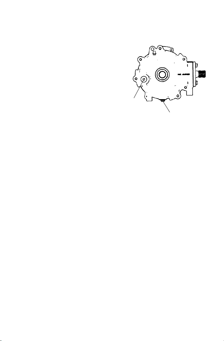
89
MAINTENANCE AND LUBRICATION
Lubrication Recommendations
Front Gearcase Oil Check
The front gearcase oil level should be
checked every six months or 1000
miles (1600 km), whichever comes
first. The oil should be changed
annually. We recommend the use of
Polaris Premium Hub Drive Fluid.
See page 121 for the part numbers of
Polaris products.
With the ATV on a level surface,
remove the fill plug and check the oil
level. The level should be maintained
3/4” below the fill plug opening.
Front Gearcase Oil Change
1. Position the vehicle on a level surface and remove the fill plug (1).
2. Place a drain pan beneath the gearcase, remove the gearcase drain
plug (2) and drain the oil.
3. Clean and reinstall the drain plug. Torque to 14 ft. lbs. (19 Nm).
4. Add 5 oz. (148 ml) of the recommended gear lube.
5. Reinstall the fill plug and check for leaks.
1
2
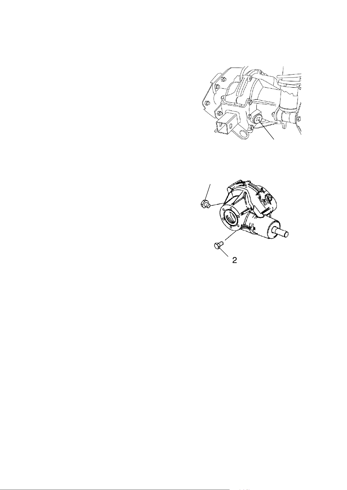
90
MAINTENANCE AND LUBRICATION
Lubrication Recommendations
Rear Gearcase Oil Check
With the ATV on a level surface,
remove the fill plug and view the oil
level through the fill hole (1).
Lubricant should be kept even with
the bottom of the fill hole. Use
Polaris Premium Synthetic Gearcase
Lube (or GL5 80-90 weight gear
lube). NOTE: See page 121 for the
part numbers of Polaris products.
Rear Gearcase Oil Change
1. Remove the drain plug (2). Catch
and discard used oil properly.
2. Clean the drain plug and inspect
the o-ring. Replace with a new
o-ring if signs of tearing or fretting
exist. Reinstall the drain plug and
torque to 40 in. lbs. (4.5 Nm).
3. Remove the fill plug and add 18
oz. (532 ml) of recommended gear
lube. Maintain the oil level at the
bottom of the fill hole.
4. Clean the fill plug and inspect the o-ring. Replace the o-ring if
it’s worn or damaged.
5. Reinstall the fill plug and torque to 40 ft. lbs. (54 Nm).
6. Check for leaks.
1
2
1
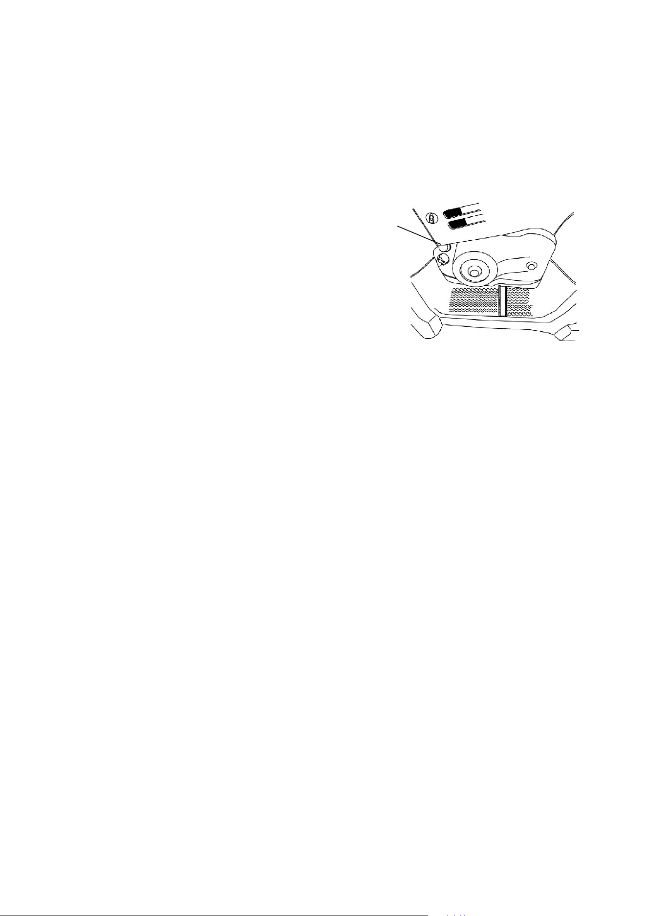
91
MAINTENANCE AND LUBRICATION
Engine Cooling System
Oil Cooler (ATP 330)
The oil cooling system requires little maintenance other than to make
sure the cooler is kept free of mud and debris. Change the engine oil
as recommended in the maintenance schedule.
Coolant Level (ATP 500)
The recovery bottle (1) is located on the
left side of the machine. To access the
recovery bottle, remove the left side panel.
See page 100.
The fluid level must be maintained
between the minimum and maximum
marks on the bottle (when the fluid is
cool).
The engine coolant level is controlled or maintained by the recovery
system. The recovery system components are the recovery bottle,
radiator filler neck, radiator pressure cap and connecting hose.
As coolant operating temperature increases, the expanding (heated)
excess coolant is forced out of the radiator, past the pressure cap, and
into the recovery bottle. As engine coolant temperature decreases, the
contracting (cooled) coolant is drawn back up from the tank, past the
pressure cap, and into the radiator.
NOTE: Some coolant level drop on new machines is normal, as the
system is purging itself of trapped air. Observe coolant levels and
maintain as recommended by adding coolant to the recovery bottle.
Polaris recommends the use of Polaris Premium 60/40
anti-freeze/coolant or a 50/50 mixture of high quality aluminum
compatible anti-freeze/coolant and distilled water. Polaris Premium
60/40 is already premixed and ready to use. Do not dilute with water.
See page 121 for the part numbers of Polaris products.
NOTE: To ensure that the coolant maintains its ability to protect the
engine, we recommend that the system be completely drained every
two years and a fresh mixture of antifreeze and water added.
NOTE: Always follow the manufacturer’s mixing recommendations
for the freeze protection required in your area.
1
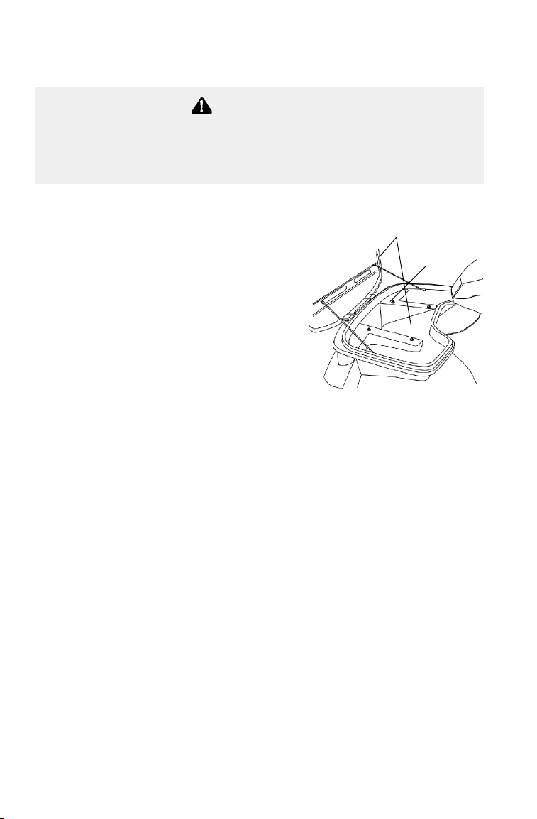
92
MAINTENANCE AND LUBRICATION
Engine Cooling System
Radiator Coolant Level (ATP 500)
NOTE: This procedure is required
only if the cooling system has been
drained for maintenance and/or repair.
However, if the recovery bottle has
run dry, the level in the radiator
should be inspected and coolant
added if necessary.
1. Using the tool provided, remove
the four screws securing the front
compartment (1). Remove the
front cover (2) by placing your
fingers under the front of the cover
and pulling upward.
2. Remove the pressure cap.
3. Using a funnel, slowly add coolant as necessary through the
radiator filler neck.
4. Replace the pressure cap and secure the front cover.
NOTE: Use of a non-standard pressure cap will not allow the
recovery system to function properly. Contact your dealer for the
correct replacement part.
WARNING
Escaping steam can cause severe burns. Never remove the
pressure cap while the engine is warm or hot. Always allow the
engine to cool before removing the pressure cap.
2
1
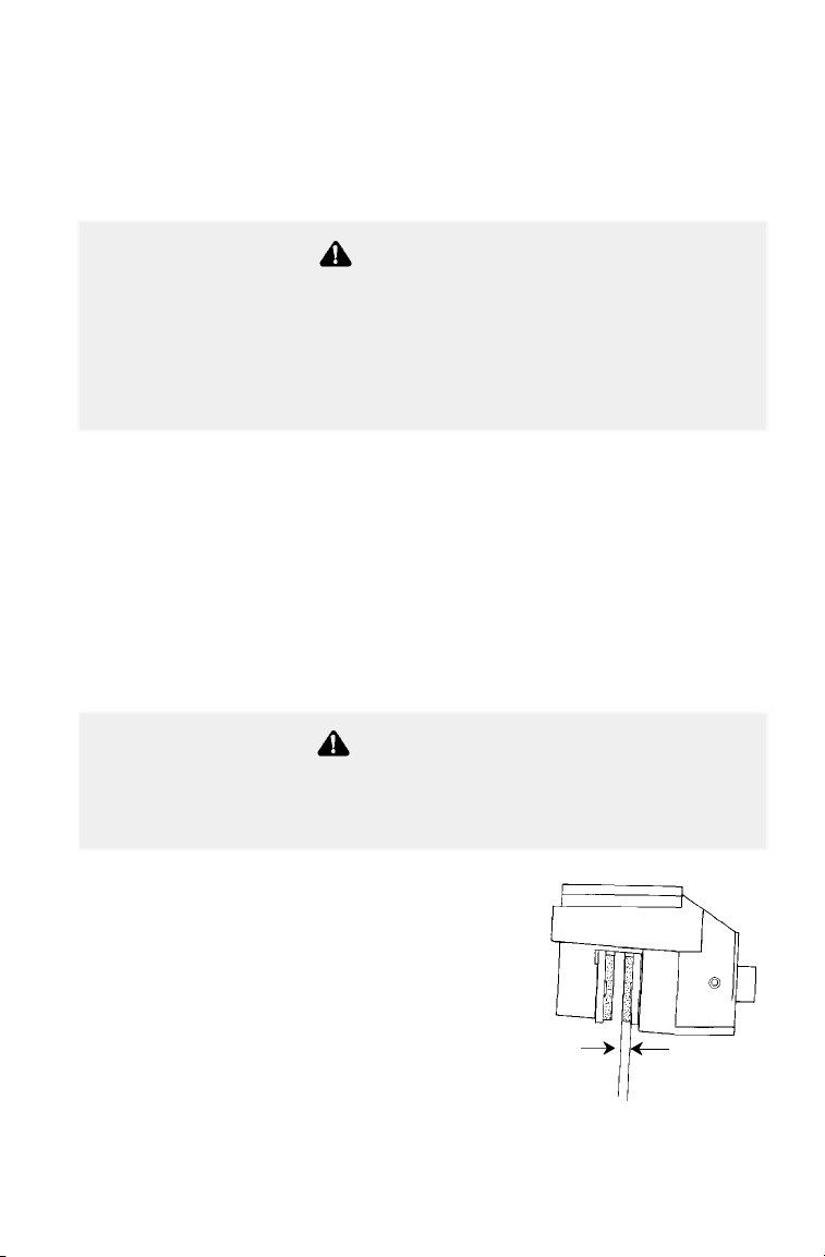
93
MAINTENANCE AND LUBRICATION
Adjustments
Brakes
The front brakes are hydraulic disc brakes, activated by moving the
brake lever toward the handlebar. These brakes are self-adjusting.
The following checks are recommended to keep the brake system in
good operating condition. Check more often if brakes are used heavily
under normal operation.
1. Always keep brake fluid at an adequate level (see page 40).
NOTE: Under normal operation, the diaphragm extends into the
reservoir as fluid level drops. If the fluid level is low and the
diaphragm is not extended, a leak is likely and the diaphragm should
be replaced. Always fill the reservoir as needed whenever the cover is
loosened or removed to ensure proper diaphragm operation. Use
Polaris DOT 3 brake fluid. Do not overfill.
2. Check the brake system for fluid
leaks.
3. Check the brakes for excessive
travel or spongy feel.
4. Check the friction pads for wear,
damage and looseness.
5. Check the security and surface
condition of the disc.
NOTE: Pads should be changed when
worn to 3/64″ (.1 cm), or about the
thickness of a U.S. dime.
Never store or use a partial bottle of brake fluid. Brake fluid is
hygroscopic, meaning it rapidly absorbs moisture from the air.
The moisture causes the boiling temperature of the brake fluid to
drop, which can lead to early brake fade and the possibility of
accident or severe injury. After opening a bottle of brake fluid,
always discard any unused portion.
WARNING
An over-full master cylinder may cause brake drag or brake lock-up,
which could result in serious injury or death. Maintain brake fluid at
the recommended level. Do not overfill.
WARNING
3/64″ (.1 cm)

94
MAINTENANCE AND LUBRICATION
Adjustments
Auxiliary Brake
The auxiliary brake is a hydraulic disc brake. The rear brake system is
self-adjusting and requires no maintenance other than periodic checks
of the pads for wear.
Pads should be changed when worn to 3/64″ (.1 cm), which is about
the thickness of a U.S. dime.
Inspect the brake disc spline and pad wear surface for excessive wear.
Your vehicle’s auxiliary brake system is intended to be used as a
backup for the main brake system. Should the main system fail, the
rear brake can be activated by depressing the foot pedal on the inside of
the right footrest.
NOTE: Since the auxiliary brake is a rear brake only, it will not be as
effective for braking as the all-wheel single lever system.
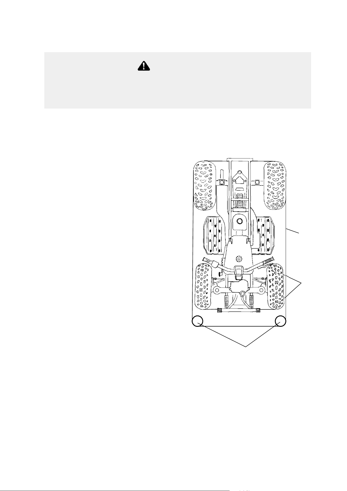
95
MAINTENANCE AND LUBRICATION
Adjustments
Toe Alignment
Use the following procedure to check the toe alignment of the vehicle.
The recommended toe alignment is 1/8″ to 1/4″ toe out.
1. Set the handlebars in a
straight-ahead position.
NOTE: The steering frog
can be used as an indicator
of whether the handlebars are
straight. The frog should
always point straight back
from the steering post.
2. Place stands (1) in front of
the vehicle, perpendicular to
the rear tires. See
illustration.
3. Tie an elastic string around
the stands, making sure the
string just touches the side
surface of the rear tires on
each side of the vehicle and
goes around the stands in
front of the vehicle (2).
4. Measure the distance from
the string to the rim at the
front and rear of the front
rim (3). Rear measurement should be 1/16″ - 1/8″ (.2 to .3 cm)
more than the front measurement.
NOTE: If you discover improper alignment, see your Polaris dealer
for service.
WARNING
Severe injury or death can result from improper toe alignment and
adjustment. Do not attempt to adjust tie rod alignment. All tie rod
adjustments should be performed by an authorized Polaris dealer.
1
2
3
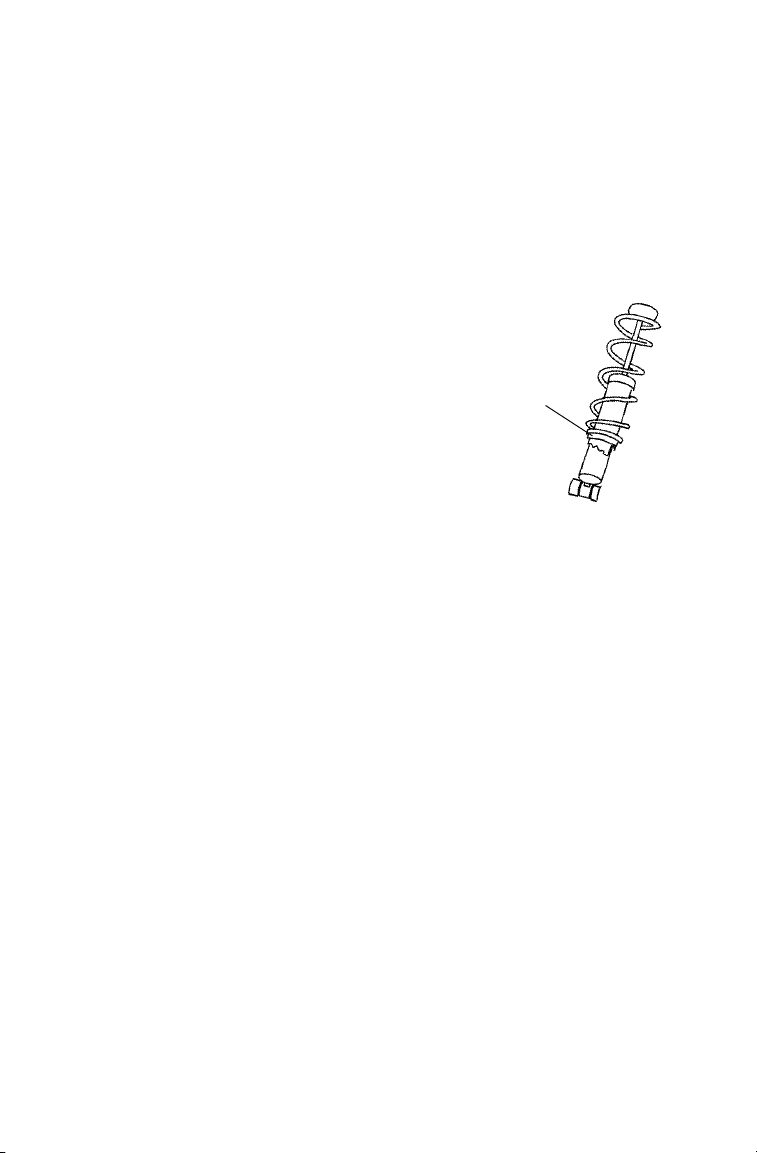
96
MAINTENANCE AND LUBRICATION
Adjustments
Steering Assembly
The steering assembly of the ATV should be checked periodically for
loose nuts and bolts. If loose nuts and bolts are found, see your Polaris
dealer for service before operating the vehicle.
Camber and Caster
The camber and caster are non-adjustable.
Rear Spring
The rear shock absorber spring is adjusted by
rotating the adjuster (1) either clockwise or
counterclockwise to increase or decrease spring
tension.
NOTE: Accessory springs are available through
your Polaris dealer.
1
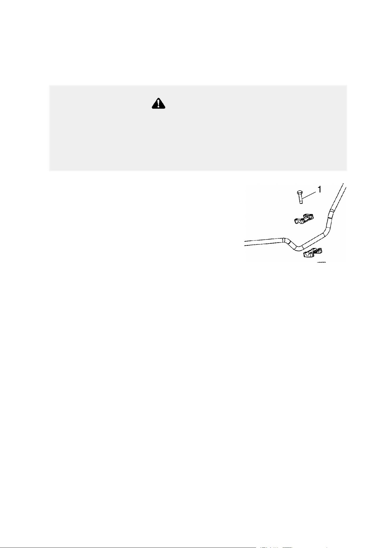
97
MAINTENANCE AND LUBRICATION
Adjustments
Handlebars
If desired, the handlebars can be adjusted for rider preference.
1. Remove the instrument panel and locate
the handlebar bolts (1).
2. Loosen the four bolts and adjust the
handlebar to the desired height. Be
sure the handlebars do not contact the
gas tank or any other part of the
machine when turned fully to the left
or right.
3. Torque the front two bolts to 10-12 ft. lbs. (14-17 Nm), then torque
the rear two bolts. A gap of up to 1/8” will remain at the rear
bolts.
Improper adjustment of the handlebars or incorrect torquing of
the adjuster block tightening bolts can cause limited steering or
loosening of the handlebars, resulting in loss of control and
possible serious personal injury or death. Follow the adjustment
procedures exactly, or see your Polaris dealer for service.
WARNING
1
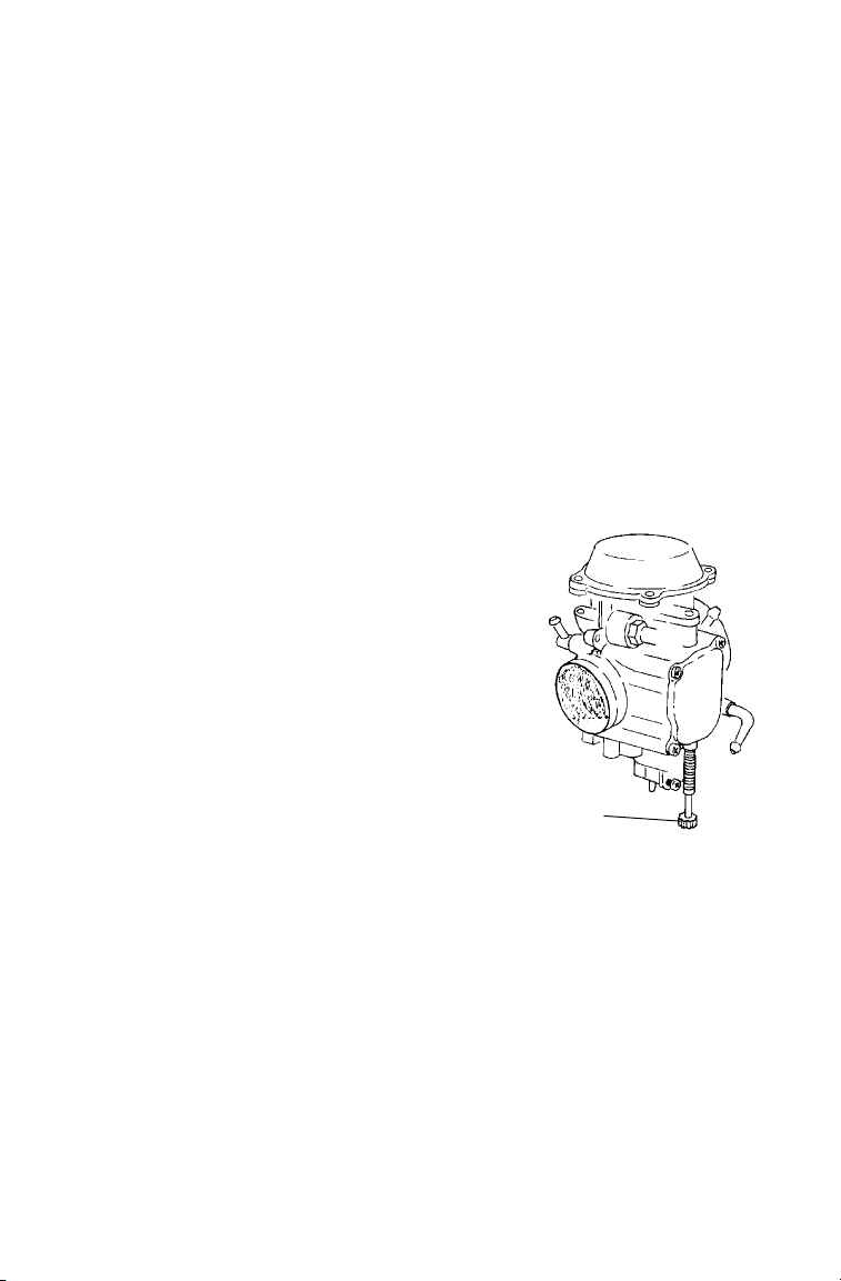
98
MAINTENANCE AND LUBRICATION
Adjustments
Carburetor
IMPORTANT: Your Polaris ATV is calibrated at the factory for
optimal performance at altitudes ranging from zero to 6,000 feet (1800
m) and temperatures of +40 degrees F. (4 degrees C.) or higher. Above
6000 feet (1800 m) the engine air/fuel mixture becomes overly rich and
the engine loses approximately 3% of its power for each 1000-foot
(304.8 m) increase in elevation. Although this power cannot be
regained, adjustments to the carburetor and drive system can be made
to allow more efficient operation. Optional jets, available from your
Polaris dealer, are required for operation above 6,000 feet and
temperatures below +40 degrees F. (4 degrees C.)
NOTE: Continuous operation of the engine without proper jetting
when required can cause poor performance, overheating or engine
damage. See your Polaris dealer for more information about jetting the
ATV for conditions in your area.
If the engine idle speed is not satisfactory,
and all other conditions are favorable, the
carburetor can be adjusted.
1. Warm up the engine by running the
vehicle for approximately five
minutes.
2. Place the transmission in gear with
the parking brake applied.
3. Adjust the carburetor idle screw (1)
either in or out until the desired idle
RPM is reached. Turning the screw
in (clockwise) will raise RPM.
Turning the screw out
(counterclockwise) will lower RPM.
1
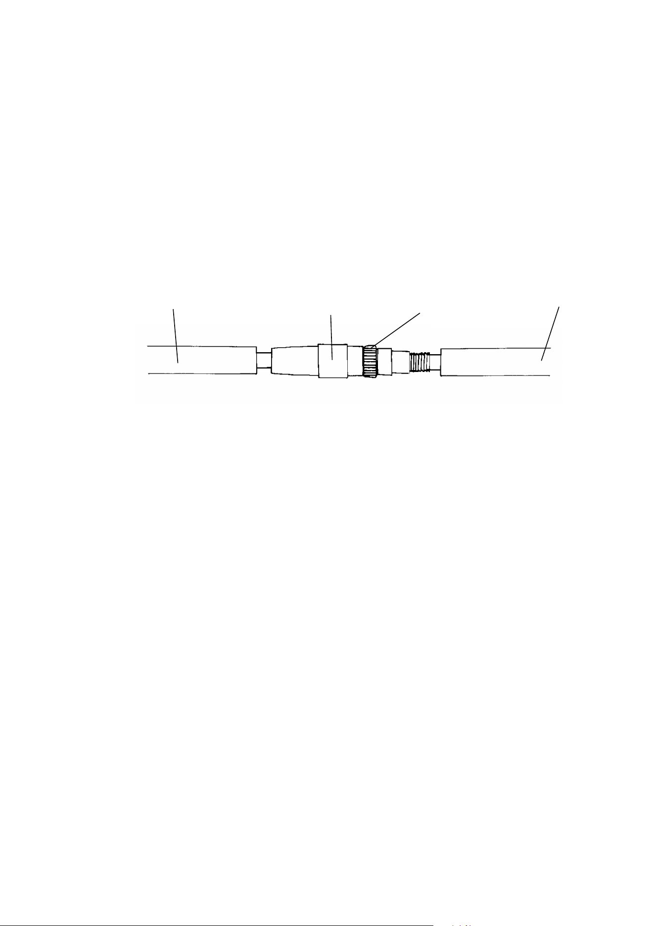
99
MAINTENANCE AND LUBRICATION
Adjustments
Throttle Cable Freeplay
Throttle cable freeplay is adjusted at the handlebar.
1. Slide the boots (1) off the inline cable adjuster sleeve (2). Loosen
the adjuster locknut (3).
2. Turn the adjuster until 1/16″ to 1/8″ freeplay is achieved at the
thumb lever. NOTE: While adjusting freeplay, be sure to flip the
throttle lever back and forth.
3. Tighten the locknut and slide the boots over the cable adjuster until
they touch at the midpoint of the adjuster.
1
2
1
3
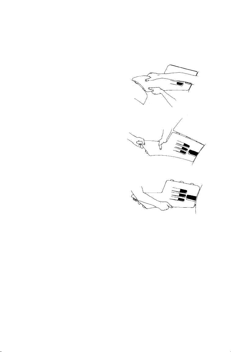
100
MAINTENANCE AND LUBRICATION
Adjustments
Side Panel Removal
NOTE: Side panel removal may be difficult until the locking tabs and
receivers have been snapped and unsnapped a few times.
1. Remove the seat.
2. Grasp the rear of the side
panel near the rear cab. With
a quick and firm motion, pull
the panel forward and outward
to disengage the two rear tabs.
3. Place your hand on top of the
side panel behind the fuel
tank. With a quick and firm
motion, push down on the side
panel to disengage the top rear
two tabs. Then pull up on the
side panel to disengage the
front upper and lower tabs.
4. To reinstall the side panel,
align the panel tabs with the
slots on the front cab. Push
the panel upward and forward
until the tabs lock. Bend the
rear of the side panel and
insert the two tabs into the rear
cab.
Step 2
Step 3
Step 4

101
MAINTENANCE AND LUBRICATION
Adjustments
Wheel Removal
1. Stop the engine, place the transmission in park and lock the
parking brake.
2. Loosen the wheel nuts slightly.
3. Elevate the side of the vehicle by placing a suitable stand under the
footrest frame.
4. Remove the wheel nuts and remove the wheel.
Operating your ATV with worn tires, improperly inflated tires,
non-standard tires or improperly installed tires will affect vehicle
handling and could cause an accident resulting in serious injury
or death.
Maintain proper tire pressure as described on the decal on your
ATV and in the specifications section of the owner’s manual
beginning on page 126.
Always use original equipment size and type when replacing
tires.
Make sure the wheels are installed properly.
Always replace tires when the tread depth measures 1/8″ (.3 cm)
or less.
WARNING
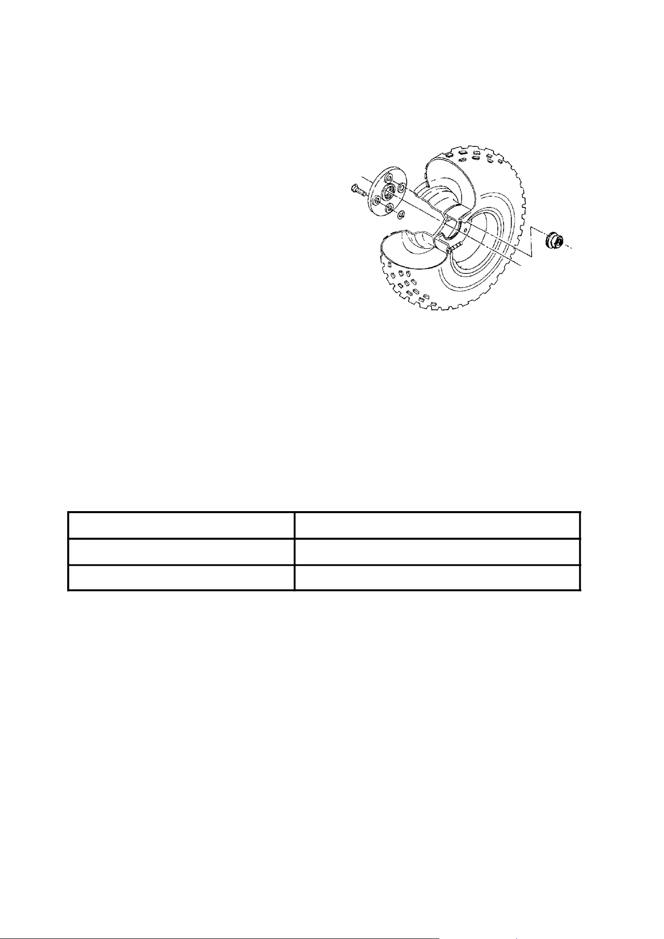
102
MAINTENANCE AND LUBRICATION
Adjustments
Wheel Installation
1. With the transmission in
park and the parking
brake locked, place the
wheel on the wheel hub
with the valve stem
toward the outside and
rotation arrows on the tire
pointing toward forward
rotation.
2. Install the wheel nuts and finger
tighten.
3. Lower the vehicle to the ground.
4. Torque the wheel nuts according to the wheel nut torque
specifications chart.
NOTE: All nuts that have a cotter pin installed must be serviced by an
authorized Polaris dealer.
Wheel Nut Torque Specifications
Check the wheel nut torques occasionally and when they’ve been
loosened for maintenance service.
Bolt Size Specification
Front 3/8″ 20 ft. lbs. (27 Nm)
Rear 3/8″ 20 ft. lbs. (27 Nm)
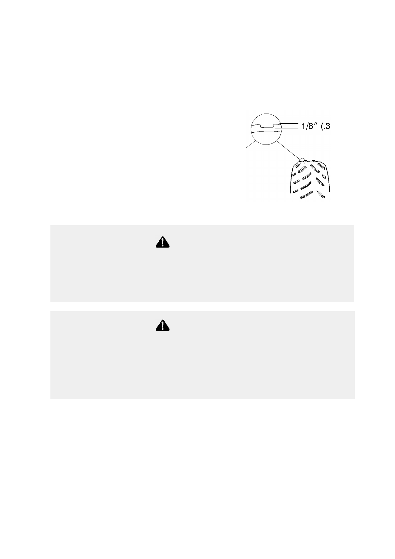
103
MAINTENANCE AND LUBRICATION
Adjustments
Front Wheel Hub Tightening
Front wheel bearing tightness and spindle nut retention are critical
component operations. All service must be performed by your
authorized Polaris dealer.
Tire Tread Depth
Always replace tires when tread
depth is worn to 1/8″ (.3 cm) or less.
See illustration.
1/8I (.3 cm)
WARNING
Operating the vehicle with worn tires will increase the possibility
of skidding, which could lead to loss of control and serious injury
or death. Always replace tires when the tread depth measures
1/8″ (.3 cm) or less.
Use of non-standard size or type of tires or improper tire inflation
may adversely affect vehicle maneuverability and cause loss of
control resulting in serious injury or death. Maintain proper tire
pressure as outlined in this owner’s manual. When replacing a
tire always use original equipment size and type.
WARNING
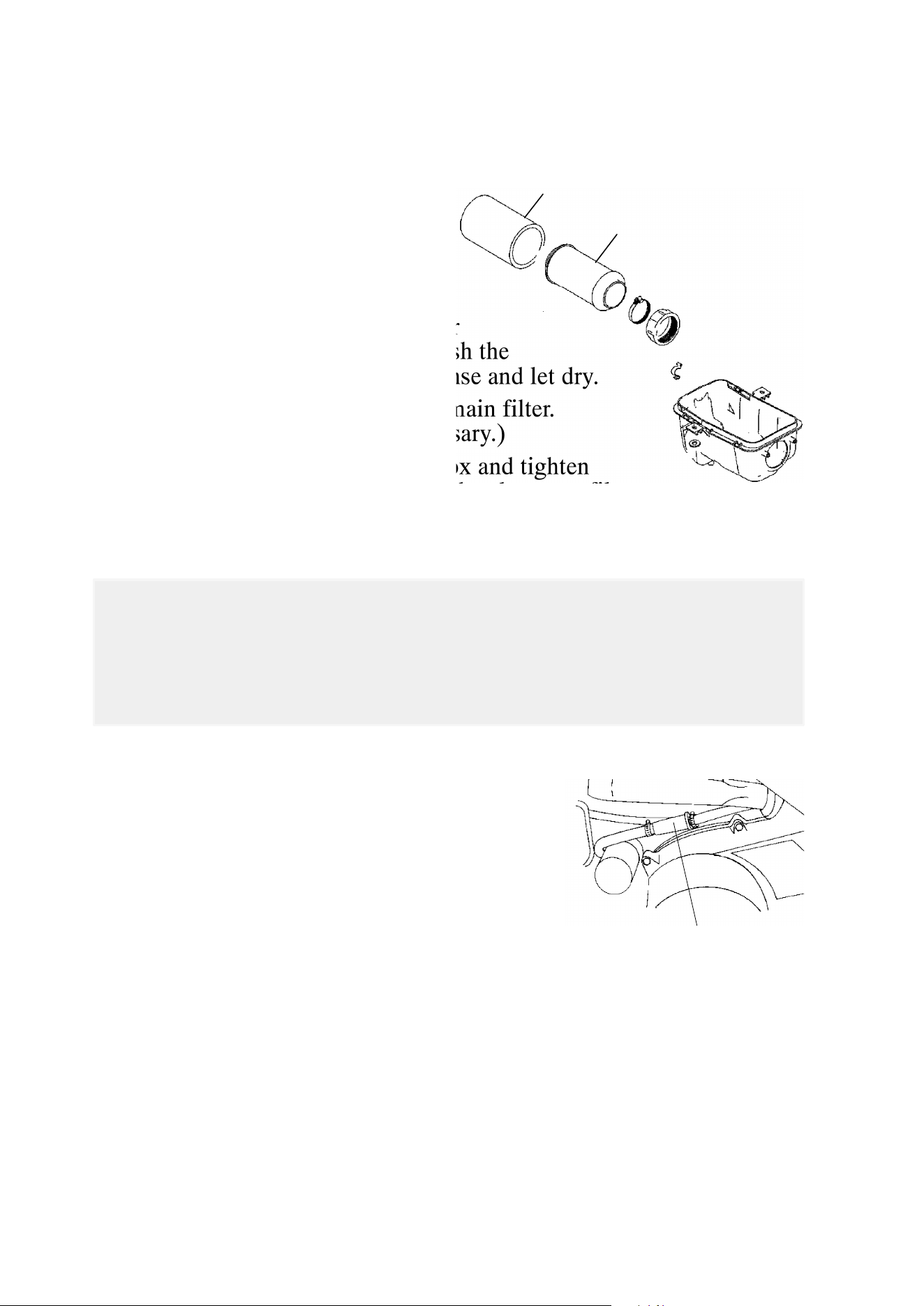
104
MAINTENANCE AND LUBRICATION
Filter Systems
Air Filter Service
1. Remove the seat, release the
clips, and remove the air
box cover.
2. Loosen the clamp and
remove the filter.
3. Remove the fabric type pre-filter
(1) from the main filter (2). Wash the
pre-filter in soapy water, then rinse and let dry.
4. Reinstall the pre-filter over the main filter.
(Replace the main filter if necessary.)
5. Reinstall the filter into the air box and tighten
the clamp. Do not over tighten the clamp, as filter
damage could occur.
Breather Filter/Hose - ATP 500 4x4
1. Remove the clamps and pull the filter (1)
out of the hoses. NOTE: It’s not
necessary to remove the lower hose
from the engine.
2. Inspect the filter for debris. Blow
gently through the filter in the direction
of the arrow to check for clogging.
Replace if needed.
3. Check the hoses for cracks,
deterioration, abrasion, or leaks. Replace as needed.
4. Reinstall the filter with the arrow pointing toward engine, and
secure the clamps.
2
1
Operation of your vehicle without a breather filter can cause
engine damage. Always reinstall the breather filter after
removing for service.
CAUTION
1

105
MAINTENANCE AND LUBRICATION
Lights
When servicing a halogen lamp, don’t touch the lamp with bare
fingers. Oil from your skin leaves a residue, causing a hot spot that
will shorten the life of the lamp.
Headlight Lamp Replacement
1. Remove the three screws on the headlight pod.
2. Using a small flat-blade screwdriver, push in on the lock tabs
through the two small openings at the front of the headlight pod.
3. Lift the pod slightly while depressing the tabs.
4. Lift the pod cover and disconnect the speedometer harnesses from
the speedometer. Unplug the indicator light harness and remove
the pod cover.
5. Unplug the headlamp from the wiring harness. Be sure to pull on
the connector, not on the wiring.
6. Grasp the bulb housing and turn counterclockwise to remove lamp.
7. Apply dielectric grease to the light bulb socket before installing the
new bulb.
8. Reverse the previous steps to replace the lamp and reassemble the
pod.
WARNING
Poor lighting while driving can result in severe injury or death.
Headlight and taillight lenses become dirty during normal operation.
Wash the headlights frequently to maintain lighting quality.
Hot components can cause serious burns to skin. Do not service
the headlamps until they’ve cooled sufficiently.
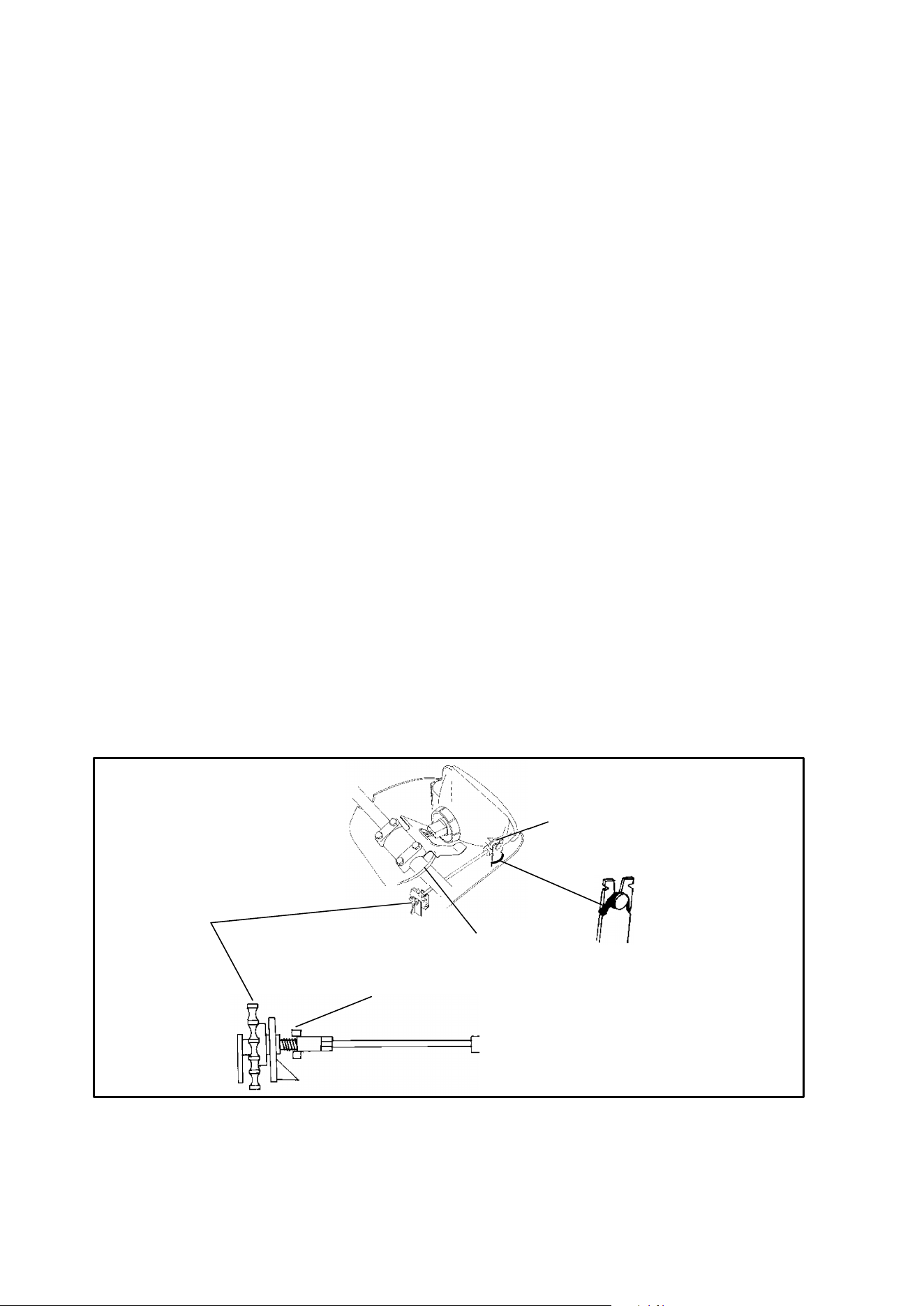
106
MAINTENANCE AND LUBRICATION
Lights
High Beam Adjustment
The headlight beam can be adjusted to any position desired by turning
the adjusting knob on the bottom right side of the headlight pod.
1. Position the vehicle on a level surface with the headlight
approximately 25 ft. (7.6 m.) from a wall.
2. Remove the two screws on the lower front corners of the headlight
pod.
3. Using a small flat-blade screwdriver, push in on the lock tab
through the two small openings at the front of the headlight pod.
4. Lift the pod slightly while depressing the tabs.
5. Remove the screw in the back of the headlight pod.
6. Measure the distance from the floor to the center of the headlight
and make a mark on the wall at the same height.
7. Start the engine and turn the headlight switch to high beam.
8. Observe the headlight aim on the wall. The most intense part of
the headlight beam should be aimed two inches (5.1 cm) below the
mark placed on the wall. NOTE: Include rider weight on the seat
when measuring.
9. Adjust the beam to the desired position by turning the adjustment
knob either clockwise or counterclockwise.
10. Reinstall the pod.
Snap pins
into tabs
Position
knob in
slot and
secure in
locking
tabs
Slip o-ring
over pin
Adjustment
Knob Stop
Route plug
over handlebar
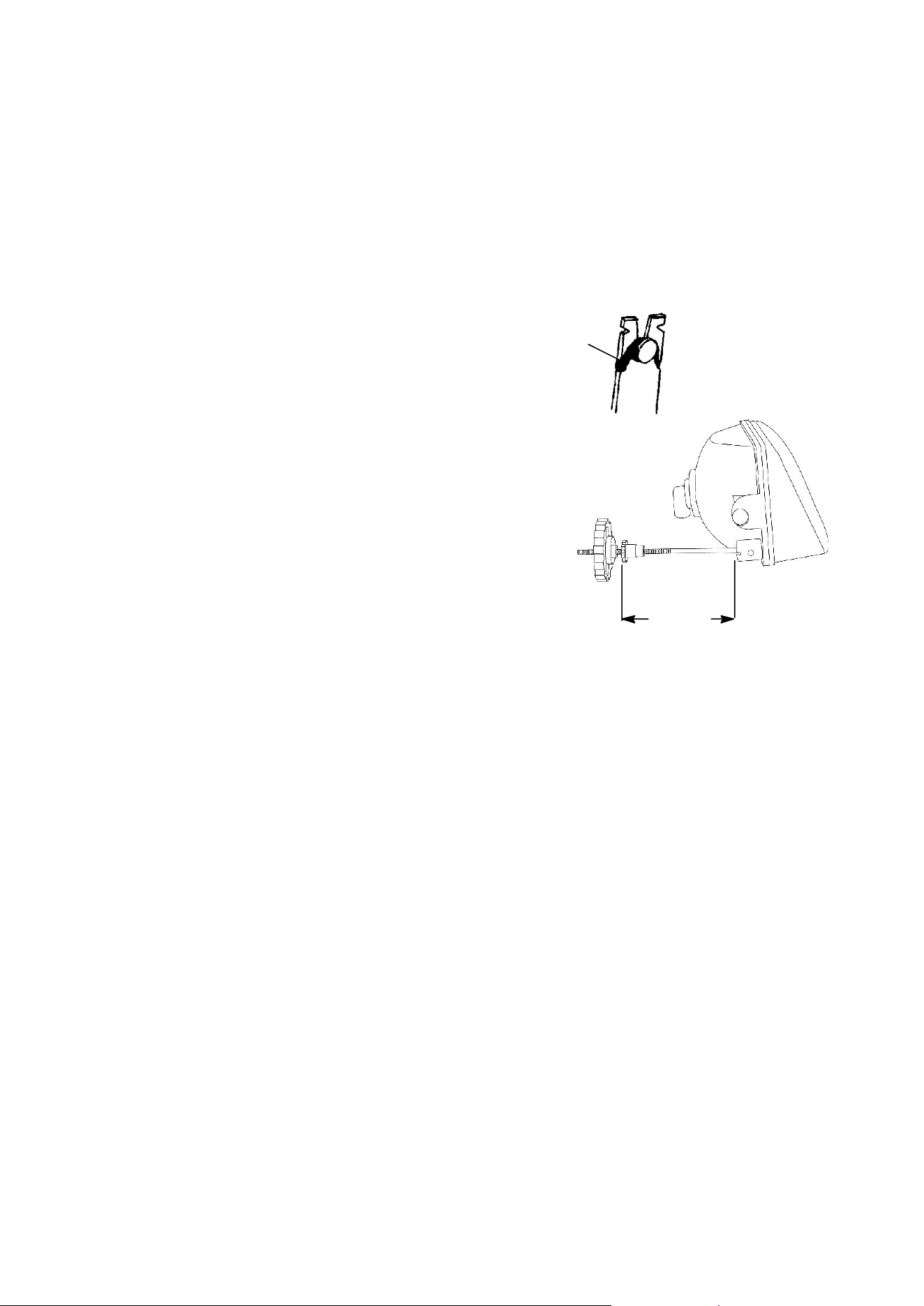
107
MAINTENANCE AND LUBRICATION
Lights
Headlight Housing Replacement
1. Remove the three screws on the headlight pod.
2. Using a small flat-blade screwdriver, push in on the lock tabs
through the two small openings at the front of the headlight pod.
Lift the pod lightly while depressing the tabs.
3. Lift the pod cover. Disconnect the
speedometer harnesses from the
speedometer. Unplug the indicator
light harness and remove the pod
cover.
4. Unplug the headlamp from the
wiring harness.
5. Remove the o-ring (1) from the
headlight pivot pins.
6. Pull the headlight housing up to
release from the locking tabs.
7. Lift the adjusting knob up to remove
from the locking tabs.
8. Carefully pull the assembly up and
out of pod.
9. Reverse the steps to install the new housing and reassemble the
pod.
NOTE: The distance from the headlamp parting line to the end of the
adjustment knob stop is 5 1/8″ (13 cm). See illustration.
10. Adjust the headlight aim by turning the adjusting knob.
1
5 1/8″
(13 cm)

108
MAINTENANCE AND LUBRICATION
Lights
Taillight/Brakelight Lamp Replacement
If the taillight/brakelight does not work, the lamp may need to be
replaced.
1. Remove the two screws securing the lens assembly.
2. Pivot the assembly outward.
3. Turn the housing clockwise and remove the bulb.
4. Install a new bulb and reinstall the taillight assembly.

109
MAINTENANCE AND LUBRICATION
Spark Plugs
S Use the recommended spark plugs for your model
(see SPECIFICATIONS beginning on page 126).
S Make sure the electrode gap meets specifications for your model.
S Torque spark plugs to 14 ft. lbs. (19 Nm).
Spark plug condition is indicative of engine operation. The spark plug
firing end condition should be read after the engine has been warmed
up and the vehicle has been driven at higher speeds. Immediately
check the spark plug for correct color.
1. Normal
The normal insulator tip is gray, tan or light brown. There will be few
combustion deposits. The electrodes are not burned or eroded. This
indicates the proper type and heat range for the engine and the service.
NOTE: The tip should not be white. A white insulator tip indicates
overheating, caused by use of an improper spark plug or incorrect
carburetion adjustments.
2. Wet Fouled
The wet fouled insulator tip is black. A damp oil film covers the firing
end. There may be a carbon layer over the entire nose. Generally, the
electrodes are not worn. General causes of fouling are excessive oil,
use of non-recommended injection oil, improper use of the choke, or
incorrect carburetion adjustments.
Spark Plug Removal and Replacement
1. Remove the spark plug cap.
2. Using the special wrench provided in the tool pouch, rotate the
spark plug counterclockwise to remove.
3. Reverse the procedure for spark plug installation. Torque to 14 ft.
lbs. (19 Nm).
Using non-recommended spark plugs can result in serious engine
damage. Always use Polaris spark plugs.
CAUTION
WARNING
A hot exhaust system and engine can cause serious burns. Wear
protective gloves when removing a spark plug for inspection.
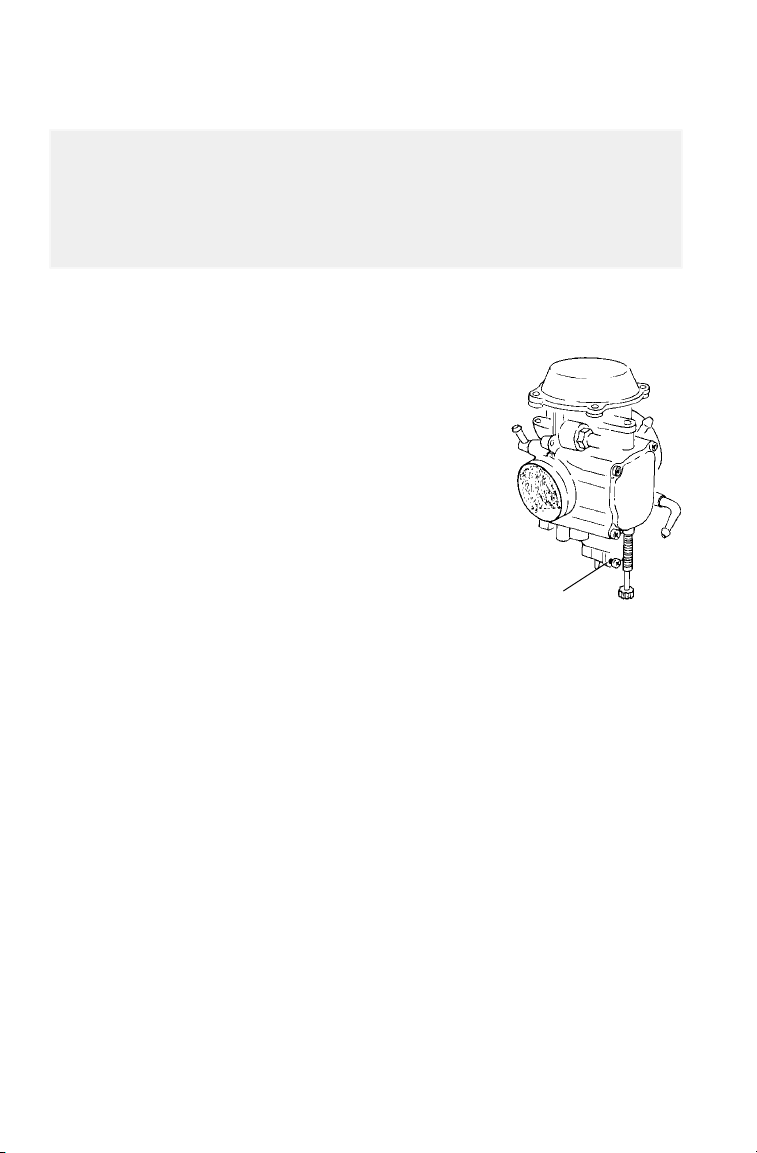
110
MAINTENANCE AND LUBRICATION
Vehicle Immersion
If it’s impossible to take your ATV to a dealer before starting it, follow
the steps outlined below.
1. Move the ATV to dry land or at the very
least, to water below the foot rests.
2. Turn the fuel valve off.
3. Remove the spark plug.
4. Check the air box and drain if water is
present.
5. Loosen the carburetor drain screw (1).
6. Turn the engine over several times using
the electric start.
7. Dry the spark plug and reinstall, or replace
it with a new plug.
8. Tighten the carburetor drain screw.
9. Turn the fuel valve on.
10. Attempt to start the engine. If necessary, repeat the drying
procedure.
11. Take the ATV to your dealer for service as soon as possible,
whether you succeed in starting it or not.
NOTE: If water has been ingested into the PVT, follow the procedure
on page 73 for drying out the PVT.
If your vehicle becomes immersed, major engine damage can
result if the machine is not thoroughly inspected. Take the vehicle
to your dealer before starting the engine.
CAUTION
1
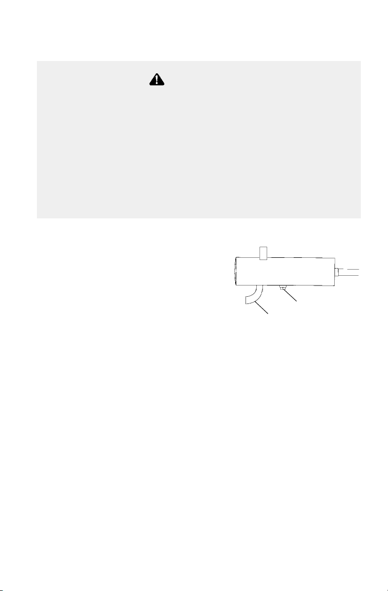
111
MAINTENANCE AND LUBRICATION
Spark Arrestor
1. Remove the arrestor clean-out
plug(s) (1) from the bottom of the
muffler.
2. Place the transmission in PARK
and start the engine.
3. Purge carbon from the system by
momentarily revving the engine
several times.
4. If carbon is expelled, cover or plug the exhaust outlet (2) and rap
on the pipe around the cleanout plug while revving the engine
several more times.
5. If particles are still suspected to be in the muffler, back the vehicle
onto an incline so the rear of the vehicle is one foot higher than the
front. Set the parking brake and block the wheels. Make sure the
vehicle is in PARK and repeat steps 3 and 4 until no more particles
are expelled when the engine is revved.
6. Stop the engine and allow the arrestor to cool. Reinstall the
arrestor plug and remove the outlet cover or plug.
WARNING
Failure to heed the following warnings while servicing the spark
arrestor could result in serious injury or death.
Do not perform service on the spark arrestor while the system is
hot. Exhaust system temperatures can reach 1000° F. Allow
components to cool sufficiently before proceeding.
Remove any combustible materials from the area. Wear eye
protection and leather work gloves. Do not stand behind or in front
of the vehicle while purging. Never run the engine in an enclosed
area. Exhaust contains poisonous carbon monoxide gas. Never go
under the vehicle while it’s inclined.
1
2

112
MAINTENANCE AND LUBRICATION
Recoil Housing
To prevent possible engine damage,
always drain the recoil housing (1) after
operating the ATV in very wet conditions.
This should also be done before storing
the ATV.
NOTE: Water will enter the recoil
housing if the starter handle is disengaged
from the rope guide when under water.
The drain screw is located at the bottom of
the recoil housing. Use a wrench to
remove the screw. Be sure to reinstall the screw after draining the
housing.
NOTE: Do not open the crankcase drain unless the engine has
ingested water. Some engine oil will be lost if the crankcase drain is
opened.
1

113
MAINTENANCE AND LUBRICATION
Battery
Battery Removal
1. Disconnect the battery hold-down strap and remove the battery cover.
2. Disconnect the black (negative) battery cable first.
3. Disconnect the red (positive) battery cable next.
4. Lift the battery out of the ATV.
Battery Installation
When installing a new battery, make sure it’s fully charged prior to its
initial use. Using a new battery that has not been fully charged can
damage the battery and result in a shorter life. It can also hinder
vehicle performance. Follow the battery charging instructions on page
114 before installing the battery.
1. Ensure that the battery is fully charged.
2. Set the battery in the battery holder.
3. Connect and tighten the red (positive) cable first.
4. Connect and tighten the black (negative) cable last.
5. Reinstall the battery cover and attach the hold-down strap.
6. Verify that cables are properly routed.
Improperly connecting or disconnecting battery cables can result
in an explosion and cause serious injury or death. When removing
the battery, always disconnect the negative (black) cable first.
When reinstalling the battery, always connect the negative (black)
cable last.
WARNING

114
MAINTENANCE AND LUBRICATION
Battery
Battery Storage
Whenever the vehicle is not used for a period of three months or more,
remove the battery from the vehicle, ensure that it’s fully charged, and
store it out of the sun in a cool, dry place. Check battery voltage each
month during storage and recharge as needed to maintain a full charge.
NOTE: Battery charge can be maintained by using a Polaris Battery
Tendert charger (PN 2871076) or by charging about once a month to
make up for normal self-discharge. Battery Tendert can be left
connected during the storage period, and will automatically charge the
battery if the voltage drops below a pre-determined point.
Battery Charging
The following battery charging instructions apply only to the
installation of a YUASA activated, sealed battery. Read all
instructions before proceeding with the installation of this battery.
The YUASA activated, sealed battery is already filled with electrolyte
and has been sealed and fully charged at the factory. Do not ever pry
the sealing strip off or add any other fluid to this battery.
The single most important thing about maintaining a sealed battery is
to keep it fully charged. Since the battery is sealed and the sealing strip
cannot be removed, you must use a voltmeter or multimeter to measure
DC voltage.
For a refresh charge, follow all instructions carefully.
1. Check the battery voltage with a voltmeter or multimeter. A fully
charged battery will register 12.8 V or higher.
2. If the voltage is less than 12.8 volts, recharge the battery at 1.2
amps or less until thebattery voltage is 12.8 or greater.
NOTE: When using an automatic charger, refer to the charger
manufacturer’s instructions for recharging. When using a constant
current charger, use the following guidelines for recharging.
An overheated battery may explode, causing severe injury or
death. Always watch charging times carefully. Stop charging if
the battery becomes very warm to the touch. Allow it to cool
before resuming charging.
WARNING

115
MAINTENANCE AND LUBRICATION
Battery
Battery Charging
NOTE: Always verify battery condition before and 1-2 hours after the
end of charging.
State of
Charge
Voltage Action Charge Time*
(Using constant current
charger @ standard amps
specified on top of battery)
100% 12.8-13.0 volts None, check at
3 mos. from date of
manufacture
None required
75%-100% 12.5-12.8 volts May need slight
charge, if no
charge given,
check in 3 months
3-6 hours
50%-75% 12.0-12.5 volts Needs Charge 5-11 hours
25%-50% 11.5-12.0 volts Needs Charge At least 13 hours,
verify state of charge
0%-25% 11.5 volts or less Needs Charge At least 20 hours

116
MAINTENANCE AND LUBRICATION
Cleaning and Storage
See page 121 for the part numbers of Polaris products.
Cleaning the ATV
Keeping your ATV clean will not only improve its appearance but it
can also extend the life of various components. With a few
precautions, your ATV can be cleaned much like an automobile.
Washing the ATV
The best and safest way to clean your ATV is with a garden hose and a
pail of mild soap and water. Use a professional type washing mitten,
cleaning the upper body first and the lower parts last. Rinse with water
frequently and dry with a chamois to prevent water spots. NOTE: If
warning and safety labels are damaged, contact your a Polaris dealer
for free replacement.
Polaris does not recommend the use of a high pressure type car wash
system for washing the ATV. If a high pressure system is used,
exercise extreme care to avoid water damage to the wheel bearings,
transmission seals, body panels, brakes and warning labels. NOTE:
Grease all zerk fittings immediately after washing, and allow the
vehicle to run for a while to evaporate any water that may have entered
the engine or exhaust system.
Waxing the ATV
Your ATV can be waxed with any non-abrasive automotive paste wax.
Avoid the use of harsh cleaners since they can scratch the body finish.
Certain products, including insect repellants and chemicals, will
damage plastic surfaces. Use caution when using these products
near plastic surfaces.
CAUTION

117
MAINTENANCE AND LUBRICATION
Cleaning and Storage
Storage Tips
See page 121 for the part numbers of Polaris products.
Clean the Exterior
Make necessary repairs and then clean the ATV thoroughly with mild
soap and warm water to remove all dirt and grime. Don’t use harsh
detergents or high pressure washers. Some detergents deteriorate rubber
parts. Use dish soap type cleaners only. High pressure washers may
force water past seals.
Stabilize the Fuel
Fill the fuel tank. Add Polaris Carbon Clean Fuel Treatment or Polaris
Fuel Stabilizer. Follow the instructions on the container for the
recommended amount. (Carbon clean will also reduce the possibility of
bacterial growth in the fuel system.) Allow 15-20 minutes of operation
for the stabilizer to disperse through the fuel in the tank and carburetor.
Turn the fuel valve off and drain the carburetor bowl.
Oil and Filter
Warm the engine and change the oil and filter.
Air Filter / Air Box
Inspect and clean or replace the pre-cleaner and air filter. Clean the air
box and drain the sediment tube.
Breather Filter
Inspect and clean or replace the breather filter.
Fluid Levels
Inspect the following fluid levels and change if necessary: front
gearcase; transmission; brake fluid (change every two years or as
required if fluid looks dark or contaminated).
Drain the Recoil Housing
Remove the recoil housing drain plug and drain any moisture.
Starting the engine during the storage period will disturb the
protective film created by fogging and damage could occur. Never
start the engine during the storage period.
CAUTION

118
MAINTENANCE AND LUBRICATION
Cleaning and Storage
Storage Tips
See page 121 for the part numbers of Polaris products.
Fog the Engine
Remove the spark plug and add 2-3 tablespoons of Premium 4 Synthetic
0W40 engine oil. To access the plug hole, use a section of clear 1/4”
hose and a small plastic squeeze bottle filled with the pre-measured
amount of oil. Note: Do this carefully! If you miss the plug hole, oil will
drain from the spark plug cavity into the hole at the front of the cylinder
head, and appear to be an oil leak. Install the spark plug and pull the
engine over slowly with the recoil starter. Oil will be forced in and
around the piston rings and ring lands, coating the cylinder with a
protective film of fresh oil.
If you choose not to use Polaris Fogging Oil, perform the following
procedure.
1. Support the front end of the machine so the engine is level or tilted
slightly rearward.
2. Remove the spark plug(s). Rotate the piston to BDC and pour
approximately two ounces of Polaris oil into the cylinder.
3. Apply dielectric grease to the inside of the spark plug cap and install
the cap onto the plug.
4. Turn the engine over several times to ensure coverage of piston
rings, cylinder walls and crankshaft bearings.
5. Treat the fuel system with Polaris Carbon Clean.
6. If Polaris fuel system additive is not used, fuel tank, fuel lines, and
carburetor should be completely drained of gasoline. To eliminate
any fuel remaining in the carburetor, run the engine until it stops.
Lubricate
Inspect all cables and lubricate with Polaris Cable Lubricant. Follow
lubrication guidelines in the maintenance section of the service or
owner’s manual to completely grease and lubricate the entire vehicle
with Polaris Premium All Season Grease.

119
MAINTENANCE AND LUBRICATION
Cleaning and Storage
Storage Tips
Battery Storage
Remove the battery from the vehicle and ensure that it’s fully charged
before placing it in storage. See page 114 for instructions.
Engine Anti-Freeze
Test engine coolant strength and change if necessary. Coolant should
be replaced every two years.
Storage Area/Covers
Set the tire pressure and safely support the ATV with the tires 1-2” off
the ground. Be sure the storage area is well ventilated, and cover the
machine with a genuine Polaris ATV cover. NOTE: Do not use plastic
or coated materials. They do not allow enough ventilation to prevent
condensation, and may promote corrosion and oxidation.
Transporting the ATV
Follow these procedures when transporting the vehicle.
1. Turn off the engine and remove the key to prevent loss during
transporting.
2. Always place the transmission in park and lock the parking brake.
3. Turn the fuel valve off.
4. Be sure the fuel cap, oil cap and seat are installed correctly.
5. Always tie the frame of the ATV to the transporting unit securely
using suitable straps or rope.

120
- NOTES -

121
POLARIS PRODUCTS
Part No. Description
Engine Lubricant
2870791 Fogging Oil (12 oz. Aerosol)
2871098 Premium 2-Cycle Engine Oil (qt.)
2871721 Premium Gold Synthetic 2-Cycle Oil (qt.)
2871281 Premium 4 Synthetic 0W-40 Engine Oil (4-Cycle)(qt.)
Gearcase / Transmission Lubricants
2873602 Premium Synthetic Gearcase Lubricant (qt.)
2871653 Gear Drive Fluid (12 oz.)
2872276 Gear Drive Fluid (2.5 gal.)
2871654 Premium Drive Hub Fluid (8 oz.)
Grease / Specialized Lubricants
2871312 Grease Gun Kit, Premium All Season (3 oz.)
2871322 Premium All Season Grease (3 oz. cartridge)
2871423 Premium All Season Grease (14 oz. cartridge)
2871460 Starter Drive Grease (2 oz.)
2871515 Premium U-Joint Lube (3 oz.)
2871551 Premium U-Joint Lube (14 oz.)
2871329 Dielectric Grease (Nyogelt)
Coolant
2871323 60/40 Coolant (gal.)
2871534 60/40 Coolant (qt.)
Additives / Miscellaneous
2871326 Carbon Clean Plus (12 oz.)
2870652 Fuel Stabilizer (16 oz.)
2870990 DOT3 Brake Fluid (12 oz.)
2872893 Engine Degreaser (12 oz.)

122
TROUBLESHOOTING
Drive Belt and Cover Problems
Possible Cause Solution
Driving the ATV onto a
pickup or tall trailer in
high range.
Shift transmission to low range during loading of the ATV
to prevent belt burning.
Starting out going up a
steep incline.
When starting out on an incline, use low range or dis-
mount the ATV (after first applying the park brake) and
perform the K-turn as described on page 66.
Driving at low RPM or
low ground speed (at
approximately 3-7 MPH).
Drive at a higher speed or use low range more frequently.
The use of low range is highly recommended for cooler
PVT operating temperatures and longer component life.
Insufficient warm-up of
ATVs exposed to low am-
bient temperatures.
Warm the engine at least 5 minutes. With the transmission
in park, advance the throttle to about 1/8 throttle in short
bursts, 5 to 7 times. The belt will become more flexible
and prevent belt burning.
Slow and easy clutch en-
gagement.
Use the throttle quickly and effectively for efficient enga-
gement.
Towing/pushing at low
RPM/low ground speed.
Use low range only.
Utility use/plowing snow,
dirt, etc.
Use low range only.
Stuck in mud or snow. Shift the transmission to low range, and carefully use fast,
aggressive throttle application to engage clutch.
WARNING: Excessive throttle may cause loss of control
and vehicle overturn.
Climbing over large ob-
jects from a stopped posi-
tion.
Shift the transmission to low range, and carefully use fast,
brief, aggressive throttle application to engage clutch.
WARNING: Excessive throttle may cause loss of control
and vehicle overturn.
Belt slippage from water
or snow ingestion into the
PVT system.
Shift the transmission to park. Using the throttle, vary the
engine RPM from idle to full throttle. Repeat several
times as required. During this procedure, the throttle
should not be held at the full position for more than 10
seconds. Clutch seals should be inspected for damage if
repeated leaking occurs.
Clutch malfunction. Contact your Polaris dealer for inspection of clutch com-
ponents.
Poor engine performance. Check for fouled plugs or foreign material in gas tank,
fuel lines, or carburetor. Contact your dealer for service.

123
TROUBLESHOOTING
Contact your Polaris dealer for service if you’re unable to identify
solutions using the following charts.
Engine Doesn’t Turn Over
Possible Cause Solution
Tripped circuit breaker Reset the breaker
Low battery voltage Recharge battery to 12.5 VDC
Loose battery connections Check all connections and tighten
Loose solenoid connections Check all connections and tighten
Engine Turns Over, Fails to Start
Possible Cause Solution
Out of fuel Turn fuel valve to reserve, refuel
Clogged fuel valve or filter Inspect and clean or replace
Water is present in fuel Drain the fuel system and refuel
Fuel valve is turned off Turn the fuel valve on
Old or non-recommended fuel Replace with new fuel
Fouled or defective spark plug(s) Inspect plug(s), replace if necessary
No spark to spark plug Inspect plug(s), verify stop switch is on
Crankcase filled with water or fuel Immediately see your Polaris dealer
Overuse of choke Inspect, clean and/or replace spark plugs
Clogged fuel filter Replace the filter
Low battery voltage Recharge battery to 12.5 VDC
Mechanical failure See your Polaris dealer
Engine Pings or Knocks
Possible Cause Solution
Poor quality or low octane fuel Replace with recommended fuel
Incorrect ignition timing See your Polaris dealer
Incorrect spark plug gap or heat range Set gap to specs or replace plugs

124
TROUBLESHOOTING
Engine Backfires
Possible Cause Solution
Weak spark from spark plugs Inspect, clean and/or replace spark plugs
Incorrect spark plug gap or heat range Set gap to specs or replace plugs
Old or non-recommended fuel Replace with new fuel
Incorrectly installed spark plug wires See your Polaris dealer
Incorrect ignition timing See your Polaris dealer
Mechanical failure See your Polaris dealer
Engine Runs Irregularly, Stalls or Misfires
Possible Weak Spark Cause Solution
Fouled or defective spark plugs Inspect, clean and/or replace spark plugs
Worn or defective spark plug wires See your Polaris dealer
Incorrect spark plug gap or heat range Set gap to specs or replace plugs
Loose ignition connections Check all connections and tighten
Water present in fuel Replace with new fuel
Low battery voltage Recharge battery to 12.5 VDC
Kinked or plugged fuel vent line Inspect and replace
Incorrect fuel Replace with recommended fuel
Clogged air filter Inspect and clean or replace
Reverse speed limiter malfunction See your Polaris dealer
Electronic throttle control malfunction See your Polaris dealer
Other mechanical failure See your Polaris dealer
Possible Lean Fuel Mixture Cause Solution
Low or contaminated fuel Add or change fuel, clean the fuel system
Low octane fuel Replace with recommended fuel
Clogged fuel filter Replace filter
Incorrect jetting See your Polaris dealer
Possible Rich Fuel Mixture Cause Solution
Overuse of choke Inspect, clean and/or replace spark plugs
Fuel is very high octane Replace with lower octane fuel
Incorrect jetting See your Polaris dealer

125
TROUBLESHOOTING
Engine Stops or Loses Power
Possible Cause Solution
Out of fuel Turn fuel valve to reserve, refuel
Kinked or plugged fuel vent line Inspect and replace
Water present in fuel Replace with new fuel
Overuse of choke Inspect, clean and/or replace spark plugs
Fouled or defective spark plugs Inspect, clean and/or replace spark plugs
Worn or defective spark plug wires See your Polaris dealer
Incorrect spark plug gap or heat range Set gap to specs or replace plugs
Loose ignition connections Check all connections and tighten
Low battery voltage Recharge battery to 12.5 VDC
Incorrect fuel Replace with recommended fuel
Clogged air filter Inspect and clean or replace
Reverse speed limiter malfunction See your Polaris dealer
Electronic throttle control malfunction See your Polaris dealer
Other mechanical failure See your Polaris dealer
Overheated engine Clean radiator screen and core if equipped
Clean engine exterior
See your Polaris dealer

126
SPECIFICATIONS
ATP 330 4x4
Gross Vehicle Weight 1300 lbs./590 kg
Fuel Capacity 3.25 gal./12.3 l
Hitch Towing Rating 1000 lbs./454 kg
Unbraked Trailer Towing Capacity* 1585 lbs./719 kg
Hitch Tongue Capacity 100 lbs./45.4 kg (rear box capacity and
tongue weight not to exceed 250 lbs./113 kg)
Front Rack & Compartment Capacity 90 lbs./40.8 kg
Rear Box Capacity 250 lbs./113 kg
Overall Length 91 in./231 cm
Overall Width 46 in./116.8 cm
Overall Height 46 in./116.8 cm
Wheelbase 56 in./142 cm
Ground Clearance 6.5 in./16.5 cm
Dry Weight 719 lbs./326 kg
Minimum Turning Radius 75 in./190.5 cm unloaded
Engine Oil Capacity 1.9 qts./1.8 l
Engine ES320PFE101
Displacement 329 cc
Bore x Stroke 78.5 x 68
Pilot Jet 42.5
Main Jet 122.5
Needle Jet P-0M
Jet Needle 4HB48-2 (2nd clip)
Pilot Screw 2 Turns Out
Alternator Output 200 w @ 5000 rpm
Compression Ratio 9.2:1 Full Stroke
Starting System Electric
Carburetor 1/BST34 (CV Type)
Ignition System CDI (Analog)
Ignition Timing 30° ± 2° @ 5000 RPM
Spark Plug / Gap NGK BKR6E / .036 in/0.9 mm
Lubrication System Wet Sump
Driving System Type PVT
* Based on EU Directive 76/432/EC

127
SPECIFICATIONS
ATP 330 4x4
Shift Type Side Lever
(High, Low, Neutral, Reverse, Park)
Gear Reduction - Low 11.57:1
Gear Reduction - Reverse 6.84:1
Gear Reduction - High 4.41:1
Drive Ratio - Front: 3.7:1
Drive Ratio - Final 3.08:1
Tire Size - Front 24 x 8 - 12
Tire Size - Rear 24 x 11 - 12
Tire Pressure- Front 5 psi
Tire Pressure- Rear 5 psi
Front/Rear Brakes Hydraulic Disc
Auxiliary Brake Hydraulic Disc
Parking Brake Hydraulic lock, all wheel
Headlight Hi/Low 30 watt
Taillights Two 12v/2.88 watt
Brake Light Two 12v/16.8 watt
Instrument Cluster LCD
Clutching and Jetting Charts
Altitude
AMBIENT
TEMPERATURE
Below 40° F
Below 5° C
+40°Fand above
+5°C to & above
Meters
(Feet)
0-1800
(0-6000)
127.5 122.5
1800-3700
(6000-12000)
120 115
Altitude Shift
Weight
Drive Clutch
Spring
Driven
Clutch
Spring
Helix*
Meters
(Feet)
0-1800
(0-6000)
20-40
PN 5631356
Blue/Gray
PN 7042202
Black
PN 7041782
41-35°
5133701
2+2
1800-3700
(6000-12000)
20-38
PN 5631357
Blue/Gray
PN 7042202
Black
PN 7041782
41-35°
5133701
2+2

128
SPECIFICATIONS
ATP 500 4x4
Gross Vehicle Weight 1500 lbs./680 kg
Fuel Capacity 3.25 gal./12.3 l
Towing Rating 1225 lbs./556 kg
Unbraked Trailer Towing Capacity* 1847 lbs./838 kg
Hitch Tongue Capacity 120 lbs./54.4 kg (Rear box capacity and
tongue weight not to exceed 400 lbs./181 kg)
Front Rack & Compartment Capacity 90 lbs./40.8 kg
Rear Box Capacity 400 lbs./181 kg
Overall Length 91 in./231 cm
Overall Width 46 in./116.8 cm
Overall Height 47 in./119.4 cm
Wheelbase 56 in./142.2 cm
Ground Clearance 7.0 in./17.8 cm
Dry Weight 738 lbs./335 kg
Minimum Turning Radius 75 in./190.5 cm unloaded
Engine Oil Capacity 2 qts./1.9 l
Coolant Capacity 3.2 qts./3.02 l
Engine EH500PLE200
Displacement 499 cc
Bore x Stroke 92 x 75
Pilot Jet 40
Main Jet 155
Needle Jet Y-0
Jet Needle 6H25-94-3
Pilot Screw 2 Turns Out
Alternator Output 250 w
Compression Ratio 10.2:1 Full Stroke
Starting System Electric
Carburetor 1/BST34
Ignition System DC CDI
Ignition Timing 30° ± 1.5° @ 3500 RPM
Spark Plug / Gap BKR5E / .028 in/0.7 mm
Lubrication System Dry Sump
Driving System Type PVT
* Based on EU Directive 76/432/EC

129
SPECIFICATIONS
ATP 500 4x4
Shift Type Side Lever
(High, Low, Neutral, Reverse, Park)
Gear Reduction - Low 8.66:1
Gear Reduction - Reverse 5.12:1
Gear Reduction - High 3.52:1
Drive Ratio - Front: 3.7:1
Drive Ratio - Final 3.08:1
Tire Size - Front 25 x 8 - 12
Tire Size - Rear 25 x 11 - 12
Tire Pressure- Front 5 psi
Tire Pressure- Rear 5 psi
Front/Rear Brakes Hydraulic Disc
Auxiliary Brake Hydraulic Disc
Parking Brake Hydraulic lock, all wheel
Headlight Single beam/60 watt
Grill - 2 single beam/27 watt
Taillights Two 12v/2.88 watt
Brake Light Two 12v/16.8 watt
Instrument Cluster LCD
Clutching and Jetting Charts
Altitude
AMBIENT
TEMPERATURE
Below 40° F
Below 5° C
+40°Fand above
+5°C to & above
Meters
(Feet)
0-1800
(0-6000)
160 155
1800-3700
(6000-12000)
152.5 147.5
Altitude Shift
Weight
Drive Clutch
Spring
Driven
Clutch
Spring
Helix*
Meters
(Feet)
0-1800
(0-6000)
10 BH
PN 5630711
Blue/Green
PN 7041157
White/Yellow
PN 7041635
EBS*
5132751
1800-3700
(6000-12000)
10 RH
PN 5630709
Blue/Green
PN 7041157
White/Yellow
PN 7041635
EBS*
5132751
EBS models require no helix / spring adjustment

130
WARRANTY
LIMITED WARRANTY
Polaris Industries Inc., 2100 Highway 55, Medina, MN 55340, gives a SIX MONTH LIM-
ITED WARRANTY on all components of the Polaris All Terrain Vehicle (ATV) against de-
fects in material or workmanship. This warranty coversthe partsand labor charges for repair
or replacement of defective parts which are covered by this warranty. This warranty begins
on the date of purchase. This warranty is transferrable to another consumer during the war-
ranty period through a Polaris dealer.
REGISTRATION
At the time of sale, the Warranty Registration Form must be completed by your dealer and
submitted to Polaris within ten days. Upon receipt of this registration, Polaris will record
the registration for warranty. THE PURCHASER MUST COMPLETE AN ATV SAFETY
TRAINING COURSE PROVIDED BY THE DEALER IN ORDER TO HAVE VALID
WARRANTY ON THE ATV. No verification of registration will be sent to the purchaser
as the copy of the Warranty Registration Form will be the warranty entitlement. If you have
not signed the original registration and received the “customer copy”, please contact your
dealer immediately. NO WARRANTY COVERAGE WILL BE ALLOWED UNLESS
YOUR ATV IS REGISTERED WITH POLARIS.
Initial dealer preparation and set-up of your ATV is very important in ensuring trouble-free
operation. Purchasing a machine in the crate or without proper dealer set-up will void your
warranty coverage.
LIMITATIONS OF WARRANTIES AND REMEDIES
The Polaris limited warranty excludes any failures that are not caused by a defect in material
or workmanship. This warranty does not cover accidental damage, normal wear and tear,
abuse or improper handling. This warranty also does not cover any ATV that has been al-
tered structurally, modified, neglected, improperly maintained, used for racing, or used for
purposes other than for which it was manufactured, or for any damages which occur during
trailer transit or as a result of unauthorized service or the use of unauthorized parts. In addi-
tion, this warranty does not cover physical damage to paint or finish, stress cracks, tearing
or puncturing of upholstery material, corrosion, or defects in parts, components or the ATV
due to fire, explosions or any other cause beyond Polaris’ control.
This warranty does not cover the use of unauthorized lubricants, chemicals, or fuels that are
not compatible with the ATV. The exclusive remedy for breach of this warranty shall be, at
Polaris’ exclusive option, repair or replacement of any defective materials, or components
or products. THE REMEDIES SET FORTH IN THIS WARRANTY ARE THE ONLY
REMEDIES AVAILABLE TO ANY PERSON FOR BREACH OF THIS WARRANTY.
POLARIS SHALL HAVE NO LIABILITY TO ANY PERSON FOR INCIDENTAL,
CONSEQUENTIAL OR SPECIAL DAMAGES OF ANY DESCRIPTION, WHETHER
ARISING OUT OF EXPRESS OR IMPLIED WARRANTY OR ANY OTHER CON-
TRACT, NEGLIGENCE, OR OTHER TORT OR OTHERWISE. Some states do not per-
mit the exclusion or limitation ofincidental or consequential damages or implied warranties,
so the above limitations or exclusions may not apply to you if inconsistent with controlling
state law.

131
WARRANTY
LIMITATIONS OF WARRANTIES AND REMEDIES
ALL IMPLIED WARRANTIES (INCLUDING BUT NOT LIMITED TO THE IMPLIED
WARRANTIES OF MERCHANTABILITY AND FITNESS FOR A PARTICULAR
PURPOSE) ARE LIMITED IN DURATION TO THE ABOVE SIX MONTH WARRAN-
TY PERIOD. POLARIS FURTHER DISCLAIMS ALL EXPRESS WARRANTIES NOT
STATED IN THIS WARRANTY. Some states do not allow limitations on how long an im-
plied warranty lasts, so the above limitation may not apply to you if inconsistent with con-
trolling state law.
HOW TO OBTAIN WARRANTY SERVICE
If your ATV requires warranty service, you must take it to a Polaris dealer authorized to re-
pair Polaris ATVs. When requesting warranty service you must present your copy of the
Warranty Registration form to the dealer. (THE COST OF TRANSPORTATION TO AND
FROM THE DEALER IS YOUR RESPONSIBILITY). Polaris suggests that you use your
original selling dealer; however, you may use any Polaris Servicing Dealer to perform war-
ranty service.
Please work with your dealer to resolve any warranty issues. Should your dealer require any
additional assistance they will contact the appropriate personnel at Polaris.
This warranty gives you specific legal rights, and you may also have other rights which vary
from state to state.
If any of the above terms are void because of state or federal law, all other warranty terms
will remain in effect.
Lubricants
1. Mixing oil brands or using non-recommended oil may cause engine damage. We recom-
mend the use of Polaris engine oil.
2. Damage resulting from the use of non-recommended lubricants may not be covered by
warranty.

132
WARRANTY
Exported Vehicles
EXCEPT WHERE SPECIFICALLY REQUIRED BY LAW, THERE IS NO
WARRANTY OR SERVICE BULLETIN COVERAGE ON THIS VEHICLE IF IT IS
SOLD OUTSIDE THE COUNTRY OF THE SELLING DEALER’S AUTHORIZED
LOCATION.
This policy does not apply to vehicles that have received authorization for export from
Polaris Industries. Dealers may not give authorization for export. You should consult an
authorized dealer to determine this vehicle’s warranty or service bulletin coverage if you
have any questions.
This policy does not apply to vehicles registered to government officials or military per-
sonnel on assignment outside the country of the selling dealer’s authorized location.
This policy does not apply to Safety Recalls.
How to Get Service
In the Country where your vehicle was purchased:
Warranty or Service Bulletin repairs must be done by an authorized Polaris dealer. If you
move or are traveling within the country where your vehicle was purchased, Warranty or
Service Bulletin repairs may be requested from any authorized Polaris dealer who sells
the same line as your vehicle.
Outside the Country where your vehicle was purchased:
If you are traveling temporarily outside the country where your vehicle was purchased,
you should take your vehicle to an authorized Polaris dealer. You must show the dealer
photo identification from the country of the selling dealer’s authorized location as proof
of residence. Upon residence verification, the servicing dealer will be authorized to per-
form the warranty repair.
If You Move:
If you move to another country, be sure to contact Polaris Customer Assistance and the
customs department of the destination country before you move. Vehicles importation
rules vary considerably from country to country. You may be required to present docu-
mentation of your move to Polaris Industries in order to continue your warranty cover-
age. You may also be required to obtain documentation from Polaris Industries in order
to register your vehicle in your new country.
How to Get Service
If Purchased From A Private Party:
If you purchase a Polaris product from a private citizen outside of the country in which
the vehicle was originally purchased, all warranty coverage will be denied.
Notice
If your vehicle is registered outside of the country where it was purchased, and you have
not followed the procedure set out above, your vehicle will no longer be eligible for war-
ranty or service bulletin coverage of any kind. (Vehicles registered to Government
officials or military personnel on assignment outside of the country where the vehicle
was purchased will continue to be covered by the basic warranty.)
For questions call Polaris Customer Assistance:
United States: 1-763-417-8650
Canada: 1-204-925-7100

133
WARRANTY
California Emission Control Warranty Statement
Your Warranty Rights and Obligations
The California Air Resources Board and Polaris Industries Inc., 2100 Highway 55,
Medina, Minnesota 55340 (herein “POLARIS”) are pleased to explain the emission
control system warranty on your 2004 and later Large Spark Ignition Engine (herein
“LSI engine”). “The California Air Resources Board has designated this engine for this
vehicle as an LSI engine which produces 25 and greater horsepower and the vehicle has
a six (6) or four (4)-wheel drive and/or a round steering wheel.” In California, this LSI
engine must be designed, built and equipped to meet the state’s stringent anti-smog stan-
dards. Polaris must warrant the emission control system on your LSI engine for the peri-
od of time described below, provided there has been no abuse, neglect or improper
maintenance of your LSI engine.
Your emission control system includes parts such as the carburetor and the ignition sys-
tem. Also included may be hoses, connectors and other emission-related assemblies.
Where a warrantable condition exists, POLARIS will repair your LSI engine at no cost to
you, including diagnosis, parts and labor.
Manufacturer’s Warranty Coverage:
The 2004 and later LSI engines are warranted for two (2) years. If any emission related
part on your LSI engine is defective, the part will be repaired or replaced by POLARIS.
Owner’s Warranty Responsibilities:
S As the LSI engine owner, you are responsible for the performance of the required
maintenance listed in your Owner’s Safety and Maintenance Manual (herein “Own-
er’s Manual”). POLARIS recommends that you retain all receipts covering mainten-
ance on your LSI engine, but POLARIS cannot deny warranty solely for the lack of
receipts or for your failure to ensure the performance of all scheduled maintenance.
S As the LSI engine owner, you should, however, be aware that POLARIS may deny
you warranty coverage if your LSI engine or a part has failed due to abuse, neglect,
improper maintenance or unapproved modifications.
S You are responsible for presenting your LSI engine to a dealer authorized by
POLARIS as soon as a problem exists. The warranty repairs should be completed in a
reasonable amount of time, not to exceed 30 days.
If you have any questions regarding your warranty rights and responsibilities, you
should contact the Polaris Warranty Department at 1-763-417-8650.
Limited Warranty
California Only
POLARIS warrants to the owner of 2004 and later LSI engines that the LSI engine (1)
has been designed, built, and equipped at the time of manufacture so as to conform with
the applicable regulations of the California Air Resources Board and, (2) is free from
defects in materials and workmanship which may cause it to fail to conform with those
regulations as applicable according to the terms and conditions stated below.

134
WARRANTY
California Emission Control Warranty Statement
Warranty Period
This warranty period begins on the date, which the LSI engine is delivered, to the origi-
nal retail purchaser and ends two years after that date. During this two year period
POLARIS warrants to the original retail purchaser and each subsequent purchaser that
the LSI engine is free from defect in material and workmanship that can cause the failure
of a warranted emission-related part.
What is Covered Under This Warranty
Repair and/or replacement of any warranted emission-related part will be performed at
no charge provided the work is performed at an authorized dealer. There will also be no
charge for any diagnostic labor performed at an authorized dealer, which leads to the
determination that a warranted emission-related part is defective.
Any warranted part which is not scheduled for replacement as required maintenance, or
which is scheduled only for regular inspection to the effect of “repair or replace as
necessary” shall be warranted for the warranty period. Any warranted part which is
scheduled for replacement as required maintenance shall be warranted for the period of
time up to the first scheduled replacement of that part. This warranty shall apply only
towards the repair, replacement, and/or adjustment of the component parts listed below.
Emission-Related Parts Covered Under This Warranty
(1) Fuel Metering System
(i) Carburetor and internal parts (and/or pressure regulator or fuel injection system).
(ii) Air/fuel ratio feedback and control system, if applicable.
(iii) Cold start enrichment system, if applicable.
(iv) Regulator assy (gaseous fuel, if applicable)
(2) Air Induction System
(i) Intake manifold, if applicable
(ii) Air filter
(3) Ignition System
(i) Spark plugs.
(ii) Magneto or electronic ignition system.
(iii) Spark advance/retard system, if applicable.
(4) Exhaust manifold, if applicable
(5) Miscellaneous Items Used in Above Systems
(i) Electronic controls, if applicable
(ii) Hoses, belts, connectors, and assemblies.
(iii) Filter lock assy (gaseous fuel, if applicable)
If an authorized dealer determines that other LSI engine components have been damaged
due to the failure of a warranted emission-related part during the warranty period,
POLARIS will repair and/or replace the necessary components.

135
WARRANTY
California Emission Control Warranty Statement
What is Not Covered Under This Warranty
This warranty does not cover any emission-related part, which malfunctions, fails, or is
damaged due to alterations and/or modifications such as changing, adding, or removing
parts.
When the LSI engine is being serviced under warranty, POLARIS and any of its
authorized dealers shall not be liable for any loss of use of the LSI engine, for any
damage to goods, or loss of time or inconvenience. This limited warranty also does not
apply to any emission-related part which malfunctions, fails, or is damaged due to failure
to follow the maintenance and operating instructions specified in the 2004 and later
Owner’s Manual including:
(a) Improper or inadequate maintenance of any warranted emission-related part
(b) Improper installation, adjustment, or repair of the LSI engine or any warranted
emission-related part unless performed by an authorized dealer
(c) Failure to use recommended fuel as specified in the 2004 and later Owner’s Manual
(d) Repairs and diagnosis performed outside of an authorized dealer
(e) Use of parts which are not authorized by POLARIS
Maintenance Schedule
The LSI engine owner is responsible for having all scheduled inspection and
maintenance services performed at the intervals specified in the 2004 and later Owner’s
Manual and to retain records of these services as having been performed. These records
should be transferred to each subsequent owner of the LSI engine. POLARIS cannot
deny a claim solely because there are no records of scheduled maintenance, however, a
warranty claim may be denied if the failure to perform the scheduled maintenance and
inspection resulted in the failure of a warranted emission-related part. As a minimum, the
LSI engine owner is responsible for the scheduled inspection and maintenance described
below which are based on the procedures described in the Owner’s Manual.
NOTE:
A. Due to the nature of these adjustments, it is recommended that an authorized dealer
perform service. Do not attempt to perform this work unless you are familiar with me-
chanical repair.
B. More often under severe use, such as dirty or wet conditions

136
WARRANTY
California Emission Control Warranty Statement
Maintenance Schedule
Item Hrs/Miles When Remarks
b Air filter
pre-cleaner
Daily Daily Inspect, clean
b Air filter main
element
Weekly Weekly Inspect, replace if
necessary
b Engine breather
filter
20 hrs. Monthly
I
nspect, replace annually
and as needed
b Engine oil level/
change
100 hrs./
1000 mi.
6 mos. Check level daily, break-in
service at one month.
Change oil more often in
cold weather use.
b Oil filter 100 hrs./
1000 mi.
6 mos. Replace with oil change
-- Engine breather
hose
100 hrs
.
6 mos. Inspect
-- Choke
(enricher) cable
50 hrs. 6 mos. Inspect, adjust, lubricate,
replace if necessary
-- Spark plug 100 hrs. 12 mos. Inspect, replace if
necessary
a Ignition timing
100 hrs
.
12 mos. Inspect, adjust as needed
a Fuel system
100 hrs
.
12 mos. Check for leaks at tank
cap, lines, fuel filter, pump
and carburetor. Replace
lines every two years.
a Valve clearance
100 hrs
.
12 mos. Inspect, adjust
Idle speed As Required
100 hrs
.
Adjust
Repair and Replacement of Emission-Related Parts
It is recommended that only LSI engine replacement parts, which have been authorized
and approved by POLARIS, should be used in the performance of any warranty
maintenance or repairs of emission-related parts. These replacement parts will be
provided at no charge if the part is still under warranty.
How to File a Warranty Claim/Where to Get Warranty Service
All repairs qualifying under this Limited Warranty must be performed by a dealer who
sold you the LSI engine or a dealer authorized by POLARIS. In the event that any
emission-related part is found to be defective during the warranty period, you must
notify the Polaris Warranty Department at 1-763-417-8650 and you will be advised of
the appropriate dealer where the warranty repair is to be performed.

137
INDEX
A
Accessories 75. . . . . . . . . . . . . . . . . . . . . .
Adjustments 93-103. . . . . . . . . . . . . . . . .
Age Restrictions 7. . . . . . . . . . . . . . . . . . .
Air Filter 104. . . . . . . . . . . . . . . . . . . . . . .
All Wheel Drive 47. . . . . . . . . . . . . . . . . .
Auxiliary Brake 42, 94. . . . . . . . . . . . . . .
AWD 47. . . . . . . . . . . . . . . . . . . . . . . . . . .
B
Battery 113-115. . . . . . . . . . . . . . . . . . . .
Battery Charging 114-115. . . . . . . . . . . .
Battery Installation 113. . . . . . . . . . . . . . .
Battery Removal 113. . . . . . . . . . . . . . . . .
Battery Storage 114, 119. . . . . . . . . . . . . .
Belt Life 45. . . . . . . . . . . . . . . . . . . . . . . .
Brake Lever 40. . . . . . . . . . . . . . . . . . . . .
Brakes 40, 93. . . . . . . . . . . . . . . . . . . . . . .
Break-In Period 53. . . . . . . . . . . . . . . . . .
Breather Filter/Hose 104. . . . . . . . . . . . . .
C
Camber and Caster 96. . . . . . . . . . . . . . . .
Carburetor 98. . . . . . . . . . . . . . . . . . . . . .
Choke 43. . . . . . . . . . . . . . . . . . . . . . . . . .
Cleaning and Storage 116-119. . . . . . . . .
Cleaning the ATV 116. . . . . . . . . . . . . . . .
Clutching and Jetting Charts 127, 129. . .
Cold Weather Operation 56. . . . . . . . . . . .
Coolant Level (ATP 500) 91. . . . . . . . . . .
Crankcase Emission Control System 74. .
D
Diagnostic Mode 51-52. . . . . . . . . . . . . .
Driving Downhill 65. . . . . . . . . . . . . . . . .
Driving in Reverse 70. . . . . . . . . . . . . . . .
Driving on Slippery Surfaces 62. . . . . . . .
Driving Over Obstacles 69. . . . . . . . . . . .
Driving Procedures 60. . . . . . . . . . . . . . . .
Driving Safely 60-71. . . . . . . . . . . . . . . .
Driving Through Water 67-68. . . . . . . . .
Driving Uphill 63. . . . . . . . . . . . . . . . . . .
Dumping Cargo 59. . . . . . . . . . . . . . . . . .
E
Electrical Switches 37-38. . . . . . . . . . . . .
EMISSION CONTROL SYSTEMS 74. . .
Engaging the Front Gearcase 47. . . . . . . .
Engine Cooling System 91-92. . . . . . . . .
Engine Fogging 118. . . . . . . . . . . . . . . . .
E
Engine Oil Check 82. . . . . . . . . . . . . . . . .
Equipment Modifications 11. . . . . . . . . . .
Exhaust Emission Control System 74. . . .
F
FEATURES AND CONTROLS 37-52. . .
Filter Systems 104. . . . . . . . . . . . . . . . . . .
Front Gearcase Oil Change 89. . . . . . . . .
Front Gearcase Oil Check 89. . . . . . . . . .
Front Wheel Hub Tightening 103. . . . . . .
Fuel Filter 43. . . . . . . . . . . . . . . . . . . . . . .
Fuel Safety 44. . . . . . . . . . . . . . . . . . . . . .
Fuel Stabilizer 117. . . . . . . . . . . . . . . . . .
Fuel Tank 43. . . . . . . . . . . . . . . . . . . . . . .
Fuel Valve 43. . . . . . . . . . . . . . . . . . . . . . .
G
Gear Selector 45. . . . . . . . . . . . . . . . . . . .
Gearcase Oil Fill Chart 88. . . . . . . . . . . . .
H
Handlebars 97. . . . . . . . . . . . . . . . . . . . . .
Hauling Cargo 57-59. . . . . . . . . . . . . . . .
Headlight Housing Replacement 107. . . .
Headlight Lamp Replacement 105. . . . . .
Helmet 36. . . . . . . . . . . . . . . . . . . . . . . . .
High Beam Adjustment 106. . . . . . . . . . .
High Range 72. . . . . . . . . . . . . . . . . . . . . .
Hour Meter 50. . . . . . . . . . . . . . . . . . . . . .
I
Instrument Cluster 49-52. . . . . . . . . . . . .
K
K-turn 66. . . . . . . . . . . . . . . . . . . . . . . . . .
L
Light Switches 38. . . . . . . . . . . . . . . . . . .
Lights 105-108. . . . . . . . . . . . . . . . . . . . .
Load Distribution 58. . . . . . . . . . . . . . . . .
Low Range 72. . . . . . . . . . . . . . . . . . . . . .
Lubrication Recommendations 80-90. . . .
M
Main Switch 37. . . . . . . . . . . . . . . . . . . . .
MAINTENANCE AND
LUBRICATION 75-119. . . . . . . . . .
Maintenance Record 81. . . . . . . . . . . . . . .
Making Turns 61. . . . . . . . . . . . . . . . . . . .

138
INDEX
N
Noise Emission Control System 74. . . . . .
O
Odometer 50. . . . . . . . . . . . . . . . . . . . . . .
Oil and Filter Change (ATP 330) 86-87. .
Oil and Filter Change (ATP 500) 83-85. .
Oil Cooler (ATP 330) 91. . . . . . . . . . . . . .
OPERATION 53-73. . . . . . . . . . . . . . . . .
Operator Safety 7-31. . . . . . . . . . . . . . . .
Override Switch 37. . . . . . . . . . . . . . . . . .
P
Parking Brake 41. . . . . . . . . . . . . . . . . . . .
Parking on an Incline 71. . . . . . . . . . . . . .
Periodic Maintenance Schedule 75-79. . .
POLARIS PRODUCTS 121. . . . . . . . . . . .
Pre Ride Inspection 54. . . . . . . . . . . . . . .
Premium 4 Synthetic Oil 82. . . . . . . . . . .
PVT Drying 73. . . . . . . . . . . . . . . . . . . . .
PVT System 72-73. . . . . . . . . . . . . . . . . .
R
Radiator Coolant Level (ATP 500) 92. . . .
Rear Gearcase Oil Change 90. . . . . . . . . .
Rear Gearcase Oil Check 90. . . . . . . . . . .
Rear Spring 96. . . . . . . . . . . . . . . . . . . . . .
Recoil Housing 112. . . . . . . . . . . . . . . . . .
Recoil Starter 46. . . . . . . . . . . . . . . . . . . .
Rider Information Center 49-52. . . . . . . .
S
Safe Riding Gear 36. . . . . . . . . . . . . . . . .
SAFETY 7-36. . . . . . . . . . . . . . . . . . . . . .
Safety Decals and Locations 32-35. . . . .
Safety Training 7. . . . . . . . . . . . . . . . . . . .
Side Panel Removal 100. . . . . . . . . . . . . .
Sidehilling 64. . . . . . . . . . . . . . . . . . . . . .
Spark Arrestor 111. . . . . . . . . . . . . . . . . .
Spark Plug Removal/Replacement 109. . .
Spark Plugs 109. . . . . . . . . . . . . . . . . . . . .
SPECIFICATIONS 126-129. . . . . . . . . . .
S
Speedo Mode Switch 37. . . . . . . . . . . . . .
Starting a Cold Engine 55. . . . . . . . . . . . .
Starting a Warm Engine 56. . . . . . . . . . . .
Starting the Engine 55-56. . . . . . . . . . . . .
Steering Assembly 96. . . . . . . . . . . . . . . .
Stop Switch 38. . . . . . . . . . . . . . . . . . . . .
Storage Tips 117-119. . . . . . . . . . . . . . . .
T
TABLE OF CONTENTS 5. . . . . . . . . . . . .
Tachometer 50. . . . . . . . . . . . . . . . . . . . . .
Taillight/Brakelight Lamp 108. . . . . . . . .
Throttle Cable Freeplay 99. . . . . . . . . . . .
Throttle Lever 39. . . . . . . . . . . . . . . . . . . .
Tire Tread Depth 103. . . . . . . . . . . . . . . .
Toe Alignment 95. . . . . . . . . . . . . . . . . . .
Towing Capacities 58. . . . . . . . . . . . . . . .
Transmission Gear Selector 45. . . . . . . . .
Transmission Oil Check 88. . . . . . . . . . . .
Transporting the ATV 119. . . . . . . . . . . . .
Trip Meter 50. . . . . . . . . . . . . . . . . . . . . .
TROUBLESHOOTING 122-125. . . . . . .
Turning Around on a Hill 66. . . . . . . . . . .
U
USFS Approved Spark Arrestor 74. . . . . .
V
VEHICLE IDENTIFICATION
NUMBERS 6. . . . . . . . . . . . . . . . . . .
Vehicle Immersion 110. . . . . . . . . . . . . . .
W
Warranty 130-136. . . . . . . . . . . . . . . . . . .
Washing the ATV 116. . . . . . . . . . . . . . . .
Waxing the ATV 116. . . . . . . . . . . . . . . . .
WELCOME 3. . . . . . . . . . . . . . . . . . . . . .
Wheel Installation 102. . . . . . . . . . . . . . .
Wheel Nut Torque Specifications 102. . . .
Wheel Removal 101. . . . . . . . . . . . . . . . .