Before using your new product, please read these instructions to prevent any damage.
INSTALLATION GUIDE
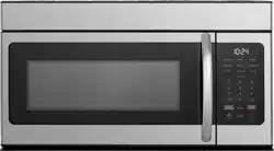
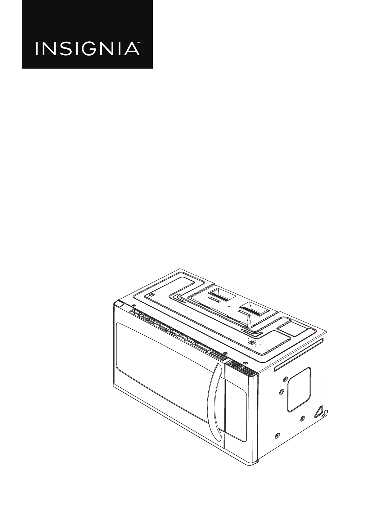
1.6 Cu. Ft.
Over-the-Range
Microwave
NS-OTR16SS9 / NS-OTR16WH9

www.insigniaproducts.com
2
Contents
Introduction . . . . . . . . . . . . . . . . . . . . . . . . . . . . . . . . . . . . . . . . . . . . . . . . . . . . . . . . . . . . . . . . . . . . . . . . . . . . . . . . . . . . . . . . . . 3
BEFORE YOU BEGIN . . . . . . . . . . . . . . . . . . . . . . . . . . . . . . . . . . . . . . . . . . . . . . . . . . . . . . . . . . . . . . . . . . . . . . . . . . . . . . . . . . . 3
IMPORTANT SAFETY INSTRUCTIONS . . . . . . . . . . . . . . . . . . . . . . . . . . . . . . . . . . . . . . . . . . . . . . . . . . . . . . . . . . . . . . . . . . . 3
ELECTRICAL REQUIREMENTS . . . . . . . . . . . . . . . . . . . . . . . . . . . . . . . . . . . . . . . . . . . . . . . . . . . . . . . . . . . . . . . . . . . . . . . . . . . . . . . . . . . . . . 3
Package contents . . . . . . . . . . . . . . . . . . . . . . . . . . . . . . . . . . . . . . . . . . . . . . . . . . . . . . . . . . . . . . . . . . . . . . . . . . . . . . . . . . . . . 4
Parts . . . . . . . . . . . . . . . . . . . . . . . . . . . . . . . . . . . . . . . . . . . . . . . . . . . . . . . . . . . . . . . . . . . . . . . . . . . . . . . . . . . . . . . . . . . . . . . . . . . . . . . . . . . . . 4
Hardware. . . . . . . . . . . . . . . . . . . . . . . . . . . . . . . . . . . . . . . . . . . . . . . . . . . . . . . . . . . . . . . . . . . . . . . . . . . . . . . . . . . . . . . . . . . . . . . . . . . . . . . . . 4
Before you install . . . . . . . . . . . . . . . . . . . . . . . . . . . . . . . . . . . . . . . . . . . . . . . . . . . . . . . . . . . . . . . . . . . . . . . . . . . . . . . . . . . . . 5
Tools and materials needed . . . . . . . . . . . . . . . . . . . . . . . . . . . . . . . . . . . . . . . . . . . . . . . . . . . . . . . . . . . . . . . . . . . . . . . . . . . . . . . . . . . . . . . 5
Mounting requirements. . . . . . . . . . . . . . . . . . . . . . . . . . . . . . . . . . . . . . . . . . . . . . . . . . . . . . . . . . . . . . . . . . . . . . . . . . . . . . . . . . . . . . . . . . . 6
Exhaust requirements. . . . . . . . . . . . . . . . . . . . . . . . . . . . . . . . . . . . . . . . . . . . . . . . . . . . . . . . . . . . . . . . . . . . . . . . . . . . . . . . . . . . . . . . . . . . . 7
Removing your microwave. . . . . . . . . . . . . . . . . . . . . . . . . . . . . . . . . . . . . . . . . . . . . . . . . . . . . . . . . . . . . . . . . . . . . . . . . . . . 9
Installing your microwave. . . . . . . . . . . . . . . . . . . . . . . . . . . . . . . . . . . . . . . . . . . . . . . . . . . . . . . . . . . . . . . . . . . . . . . . . . . . 10
Step 1: Find the wall studs . . . . . . . . . . . . . . . . . . . . . . . . . . . . . . . . . . . . . . . . . . . . . . . . . . . . . . . . . . . . . . . . . . . . . . . . . . . . . . . . . . . . . . . 10
Step 2: Align the rear wall template. . . . . . . . . . . . . . . . . . . . . . . . . . . . . . . . . . . . . . . . . . . . . . . . . . . . . . . . . . . . . . . . . . . . . . . . . . . . . . . 11
Step 3: Select a ventilation type . . . . . . . . . . . . . . . . . . . . . . . . . . . . . . . . . . . . . . . . . . . . . . . . . . . . . . . . . . . . . . . . . . . . . . . . . . . . . . . . . . 13
Step 4: Option A - Attach the mounting plate to the wall . . . . . . . . . . . . . . . . . . . . . . . . . . . . . . . . . . . . . . . . . . . . . . . . . . . . . . . . . . 14
Step 5: Option A - Preparing the top cabinet . . . . . . . . . . . . . . . . . . . . . . . . . . . . . . . . . . . . . . . . . . . . . . . . . . . . . . . . . . . . . . . . . . . . . . 16
Step 6: Option A - Insert the exhaust adapter . . . . . . . . . . . . . . . . . . . . . . . . . . . . . . . . . . . . . . . . . . . . . . . . . . . . . . . . . . . . . . . . . . . . . 18
Step 7: Option A - Mount the microwave . . . . . . . . . . . . . . . . . . . . . . . . . . . . . . . . . . . . . . . . . . . . . . . . . . . . . . . . . . . . . . . . . . . . . . . . . 19
Step 8: Option A - Connecting ductwork. . . . . . . . . . . . . . . . . . . . . . . . . . . . . . . . . . . . . . . . . . . . . . . . . . . . . . . . . . . . . . . . . . . . . . . . . . 21
Step 4: Option B - Cutting a vent opening. . . . . . . . . . . . . . . . . . . . . . . . . . . . . . . . . . . . . . . . . . . . . . . . . . . . . . . . . . . . . . . . . . . . . . . . . 22
Step 5: Option B - Attach the mounting plate to the wall . . . . . . . . . . . . . . . . . . . . . . . . . . . . . . . . . . . . . . . . . . . . . . . . . . . . . . . . . . 23
Step 6: Option B - Preparing the top cabinet . . . . . . . . . . . . . . . . . . . . . . . . . . . . . . . . . . . . . . . . . . . . . . . . . . . . . . . . . . . . . . . . . . . . . . 25
Step 7: Option B - Adapt the microwave blower for outside back exhaust . . . . . . . . . . . . . . . . . . . . . . . . . . . . . . . . . . . . . . . . . . 27
Step 8: Option B - Mount the microwave. . . . . . . . . . . . . . . . . . . . . . . . . . . . . . . . . . . . . . . . . . . . . . . . . . . . . . . . . . . . . . . . . . . . . . . . . . 30
Step 4: Option C - Attach the mounting plate to the wall . . . . . . . . . . . . . . . . . . . . . . . . . . . . . . . . . . . . . . . . . . . . . . . . . . . . . . . . . . 32
Step 5: Option C - Preparing the top cabinet . . . . . . . . . . . . . . . . . . . . . . . . . . . . . . . . . . . . . . . . . . . . . . . . . . . . . . . . . . . . . . . . . . . . . . 34
Step 6: Option C - Adapting blower for recirculation . . . . . . . . . . . . . . . . . . . . . . . . . . . . . . . . . . . . . . . . . . . . . . . . . . . . . . . . . . . . . . 36
Step 7: Option C - Mount the microwave. . . . . . . . . . . . . . . . . . . . . . . . . . . . . . . . . . . . . . . . . . . . . . . . . . . . . . . . . . . . . . . . . . . . . . . . . . 39
Before using your microwave . . . . . . . . . . . . . . . . . . . . . . . . . . . . . . . . . . . . . . . . . . . . . . . . . . . . . . . . . . . . . . . . . . . . . . . . 41
Template dimensions . . . . . . . . . . . . . . . . . . . . . . . . . . . . . . . . . . . . . . . . . . . . . . . . . . . . . . . . . . . . . . . . . . . . . . . . . . . . . . . .42
Rear wall template dimensions . . . . . . . . . . . . . . . . . . . . . . . . . . . . . . . . . . . . . . . . . . . . . . . . . . . . . . . . . . . . . . . . . . . . . . . . . . . . . . . . . . . 42
Top cabinet template dimensions . . . . . . . . . . . . . . . . . . . . . . . . . . . . . . . . . . . . . . . . . . . . . . . . . . . . . . . . . . . . . . . . . . . . . . . . . . . . . . . . 43
Obtaining replacement parts. . . . . . . . . . . . . . . . . . . . . . . . . . . . . . . . . . . . . . . . . . . . . . . . . . . . . . . . . . . . . . . . . . . . . . . . .44
Specifications. . . . . . . . . . . . . . . . . . . . . . . . . . . . . . . . . . . . . . . . . . . . . . . . . . . . . . . . . . . . . . . . . . . . . . . . . . . . . . . . . . . . . . . . 44
Legal notices . . . . . . . . . . . . . . . . . . . . . . . . . . . . . . . . . . . . . . . . . . . . . . . . . . . . . . . . . . . . . . . . . . . . . . . . . . . . . . . . . . . . . . . . 44
ONE-YEAR LIMITED WARRANTY . . . . . . . . . . . . . . . . . . . . . . . . . . . . . . . . . . . . . . . . . . . . . . . . . . . . . . . . . . . . . . . . . . . . . . 45
www.insigniaproducts.com
3
NS-OTR16SS9 / NS-OTR16WH9
Introduction
Congratulations on your purchase of a high-quality Insignia product. Your NS-OTR16SS9 / NS-OTR16WH9 represents the
state of the art in microwave design and is designed for reliable and trouble-free performance.
This installation guide will show you how to install your new over-the-range microwave.
BEFORE YOU BEGIN
Read these instructions completely and carefully.
• IMPORTANT – Save these instructions for local inspector’s use.
• IMPORTANT – Observe all governing codes and ordinances.
• Note to Installer – Be sure to leave these instructions with the consumer.
• Note to Consumer – Keep these instructions for future reference.
• Skill level – Installation of this appliance requires basic mechanical and electrical skills.
• Proper installation is the responsibility of the installer.
• Product failure due to improper installation is not covered under the Warranty.
IMPORTANT SAFETY INSTRUCTIONS
IMPORTANT–PLEASE READ CAREFULLY. FOR PERSONAL SAFETY, THIS APPLIANCE MUST BE PROPERLY GROUNDED TO
AVOID SEVERE OR FATAL SHOCK.
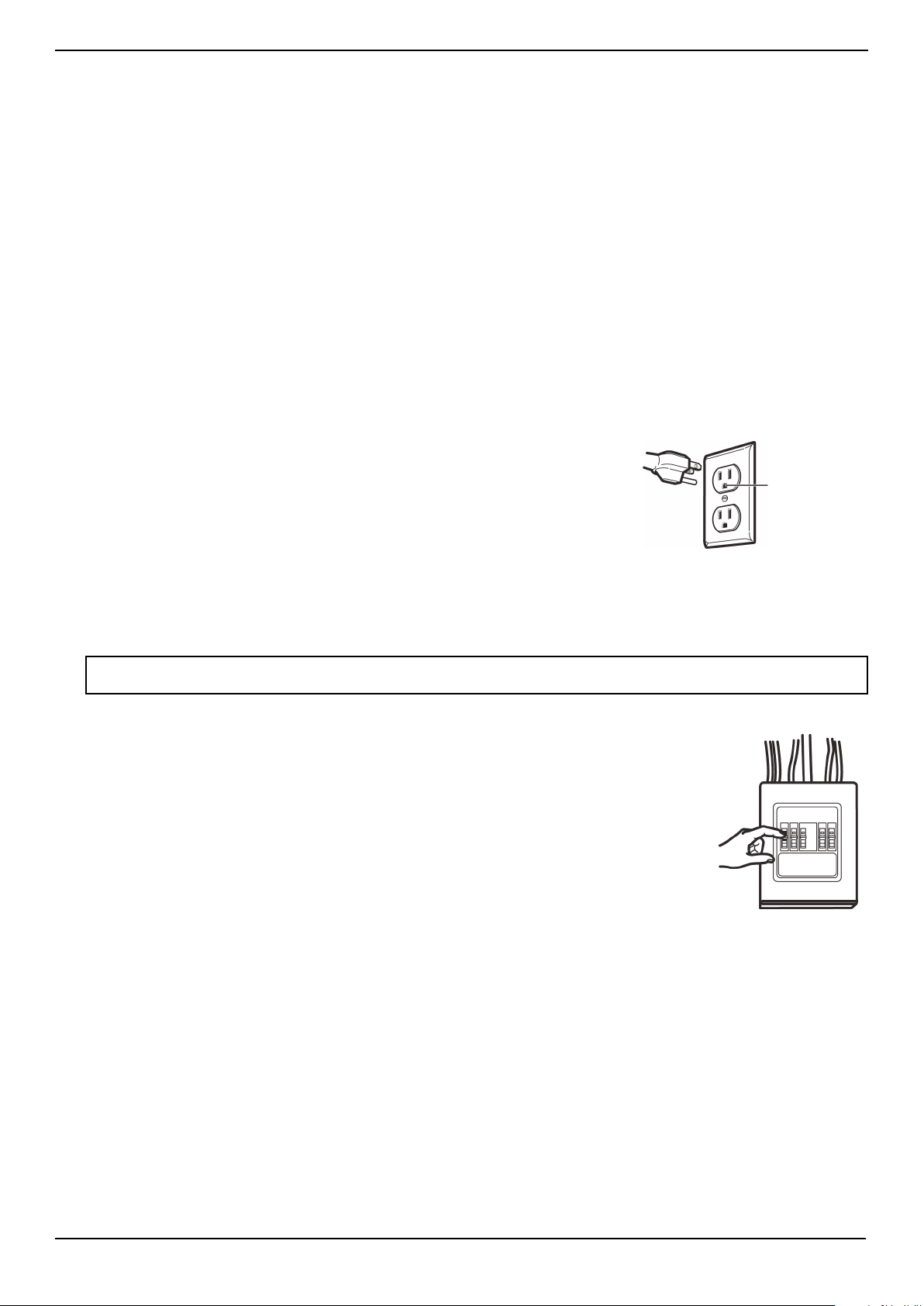
This product requires a three-prong, properly grounded outlet for safe operation. If
not properly grounded, or if the outlet box does not meet electrical requirements
noted (under ELECTRICAL REQUIREMENTS), a qualified electrician should be
employed to correct any deficiencies.
The power cord of this appliance is equipped with a three-prong (grounding) plug
which mates with a standard three-prong (grounding) wall receptacle to minimize the
possibility of electric shock hazard from this appliance.
You should have the wall receptacle and circuit checked by a qualified electrician to
make sure that the receptacle is properly grounded.
Where a standard two-prong wall receptacle is encountered, it is very important to have it replaced with a properly
grounded three-prong wall receptacle installed by a qualified electrician.
DO NOT, UNDER ANY CIRCUMSTANCES, CUT, DEFORM, OR REMOVE ANY OF THE PRONGS FROM THE POWER CORD. DO
NOT USE WITH AN EXTENSION CORD.
CAUTION
For personal safety, remove the house fuse or open the circuit breaker before beginning
installation to avoid severe or fatal shock injury.
For personal safety, the mounting surface must be capable of supporting the cabinet load, in
addition to the added weight of this 54 pound (24 kilogram) product, plus additional oven loads
of up to 50 pounds (22 kilograms) for a total weight of 104 pounds (47 kilograms).
For personal safety, this product cannot be installed in cabinet arrangements such as an island or
a peninsula. It must be mounted to BOTH a top cabinet AND a wall.
ELECTRICAL REQUIREMENTS
The product rating of your microwave is 120 volts AC, 60 Hertz, 14 amps, and 1.55 kilowatts. This
product must be connected to a supply circuit of the proper voltage and frequency. Wire size
must conform to the requirements of the National Electrical Code or the prevailing local code for this kilowatt rating. The
power supply cord and plug should be brought to a separate 20 ampere branch circuit single grounded outlet. The outlet
box should be located in the cabinet above the microwave oven. The outlet box and supply circuit should be installed by a
qualified electrician and conform to the National Electrical Code or the prevailing local code.
Note: For easier installation and personal safety, we recommend that two people install this product because of the weight. We highly
recommend professional installation if any electrical or carpentry work is required.
Ensure
proper
ground
before use
www.insigniaproducts.com
4
Package contents
• 1.6 cu. ft. over-the-range microwave
• Turntable (with ring)
• Installation parts (“Parts” on page 4)
• Installation hardware (see “Hardware” on page 4)
• Mounting templates (2)
• Installation Guide
• User Guide
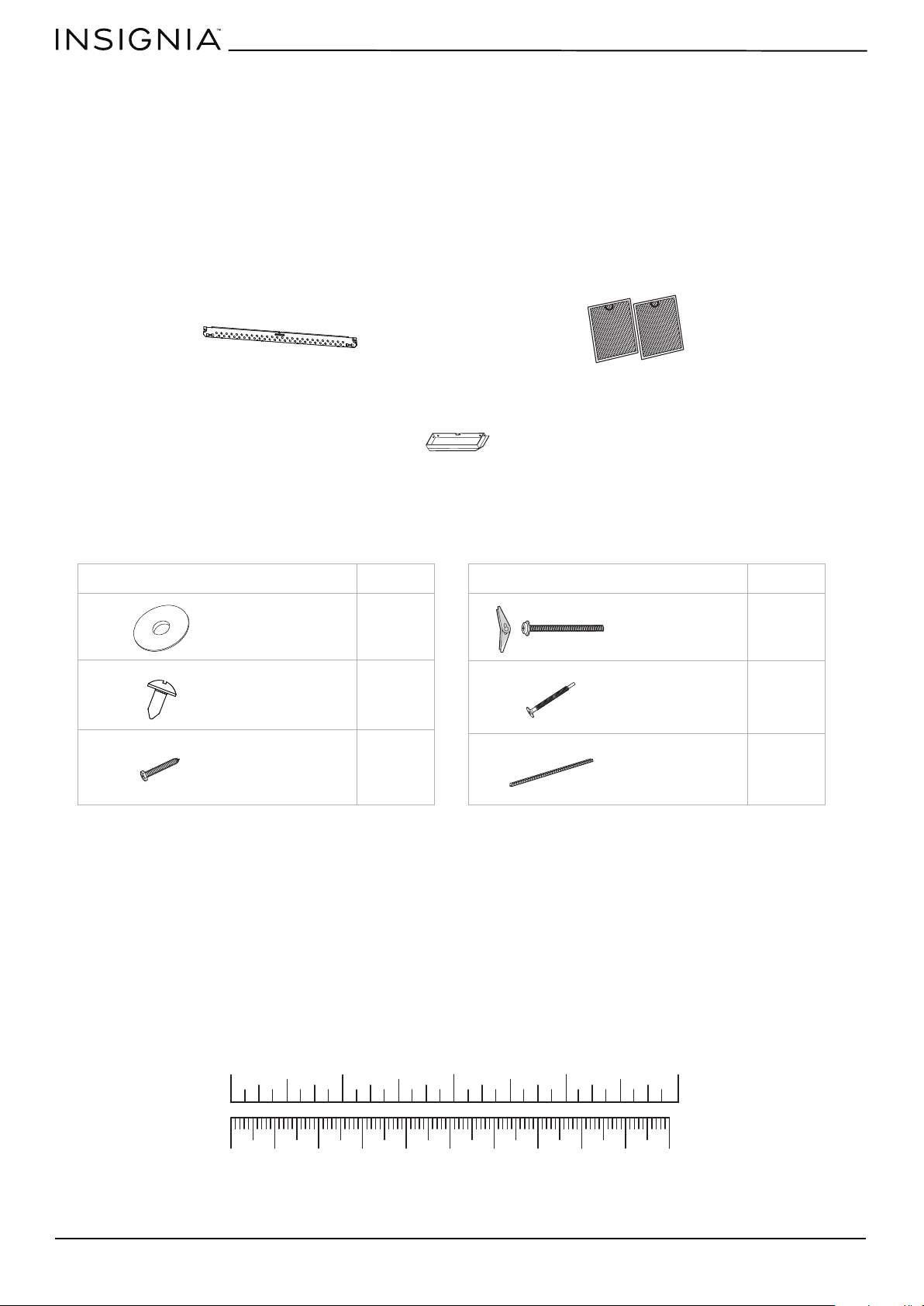
Parts
Make sure that you have all the parts necessary to install your new microwave.
Hardware
Mounting plate (Qty. 1)
Exhaust adapter (Qty. 1)
Grease filters (Qty. 2)
HARDWARE QTY.
2
2
2
Washers
Sheet metal
screws
Wood screws
(1/4” × 2”)
HARDWARE QTY.
2
2
1
Toggle bolts
with wing nuts
(3/16” × 3”)
Self-aligning
machine screws
(20-1/4” × 3”)
Nylon grommet
10 20 30 40 50 60 70 80 90 100mm
1234in
www.insigniaproducts.com
5
NS-OTR16SS9 / NS-OTR16WH9
Before you install
Read these instructions completely before installing your microwave. Make sure that your space meets the mounting
requirements and that you’ve gathered all needed tools and materials.
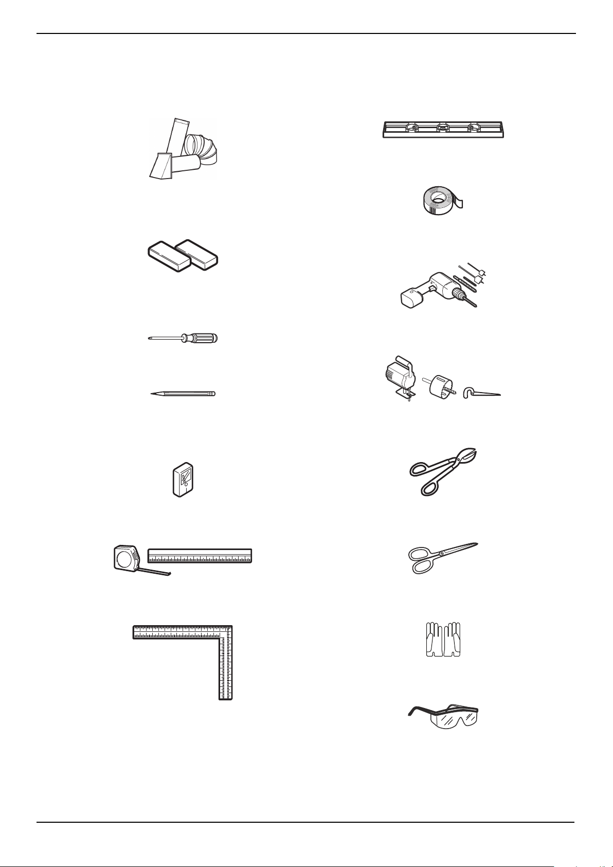
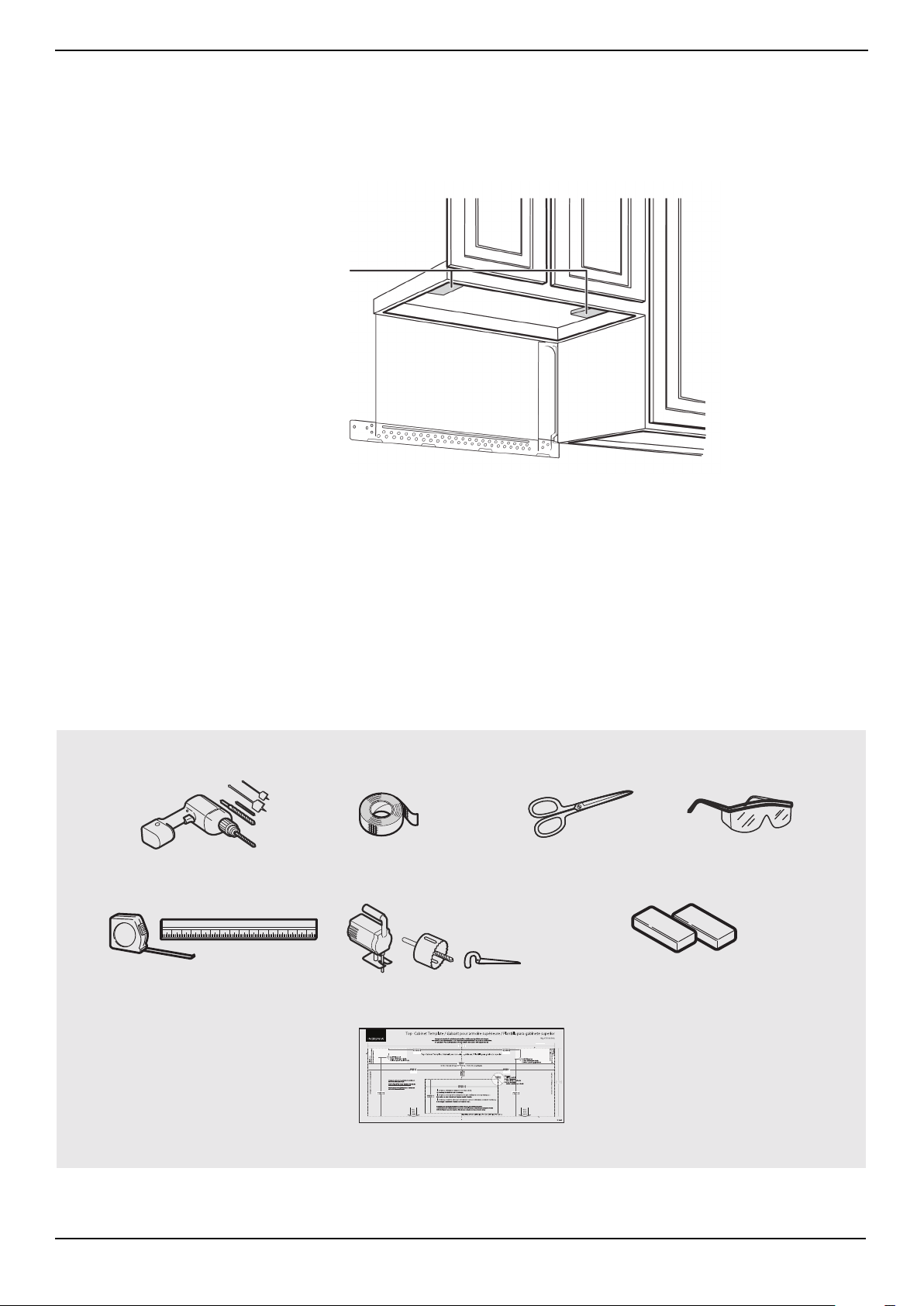
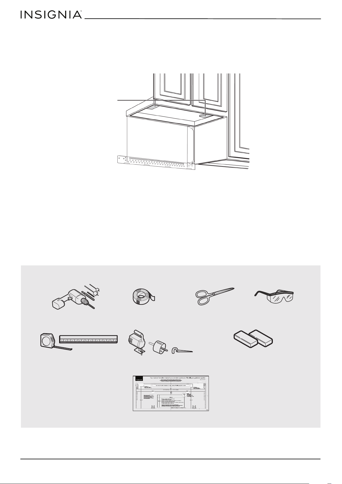
Tools and materials needed
#1 and #2 Phillips screwdrivers
Pencil
Tin snips
(to cut damper, if needed)
Scissors
(to cut template, if needed)
Gloves
Safety goggles
Saw
(saber, hole, or keyhole)
Ruler or tape measure
Electric drill with 3/16”, 1/2”, and 5/8” bits
Edge-to-edge stud finder
Level
Duct tape
Filler blocks or scrap wood pieces
(for top cabinet spacing in recessed
bottom cabinet installations, if needed)
Carpenter square
(optional)
Ducts (if venting outside)
See “Exhaust requirements” on page 7
www.insigniaproducts.com
6
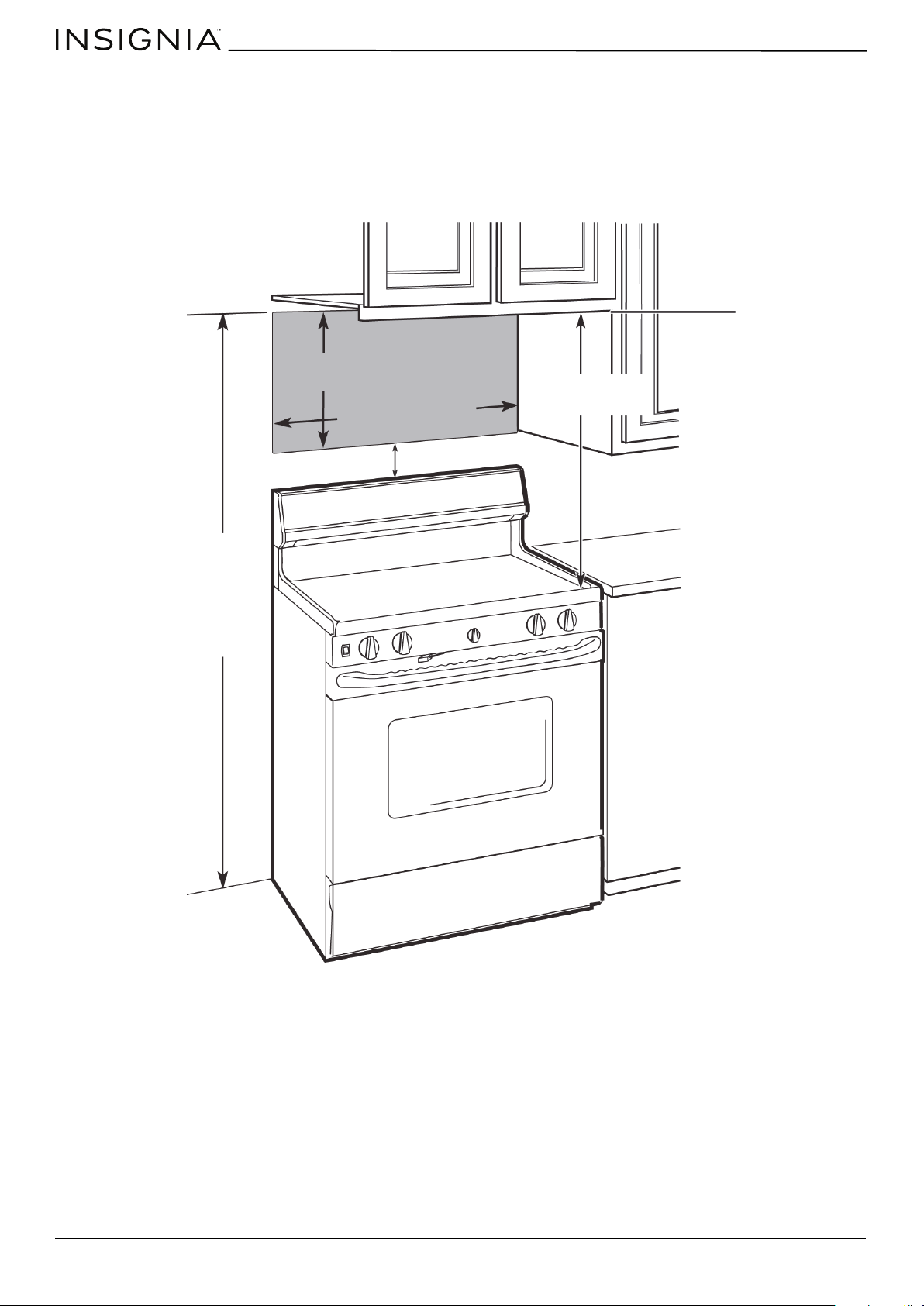
Mounting requirements
• The space between the cabinets must be 30 in. (76.2 cm) wide. If the space between the cabinets is more than 30 in.
(76.2 cm), you’ll need filler material to fill the gap between the microwave and cabinets.
• This microwave is for installation over ranges up to 36 in. (91.4 cm) wide.
• If installing the microwave beneath smooth, flat cabinets, make sure that you leave enough space for the power cord
clearance.
• If you are going to vent your exhaust to the outside, see “Exhaust requirements” on page 7 for exhaust duct
preparation.
66 in. (167.6 cm) or more
from the floor to the top
of the microwave
16-1/2 in.
(41.9 cm)
30 in. (76.2 cm)
30 in.
(76.2 cm)
2 in. (5.1 cm)
www.insigniaproducts.com
7
NS-OTR16SS9 / NS-OTR16WH9
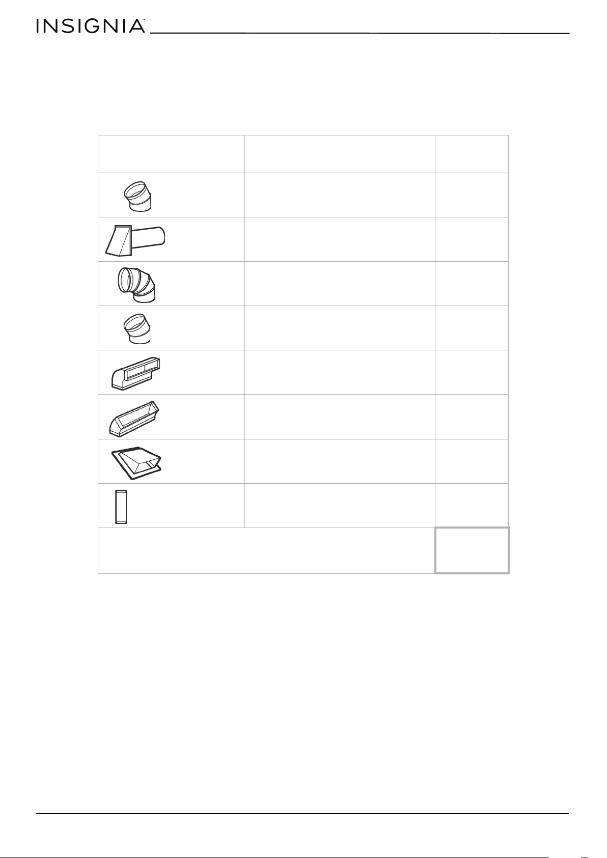
Exhaust requirements
Use this section if you plan to vent your microwave outside (top or back exhaust). If you plan to recirculate the air back into
the room, skip to “Removing your microwave” on page 9.
When installing exhaust vents:
• Use the most direct route with as few elbows/transitions as possible. This helps prevent blockages and ensures that the
exhaust is being vented correctly.
• Your microwave is designed to mate with a standard 3-1/4” × 10” rectangular duct. If a round duct is required, a
rectangular-to-round transition adapter must be used. Do not use a duct with a diameter less than 6”.
• Elbows, transitions, and wall/roof caps add resistance to airflow. Each of these pieces are equivalent to a section of
straight duct that is longer than their actual physical size. When calculating your duct length, add the equivalent
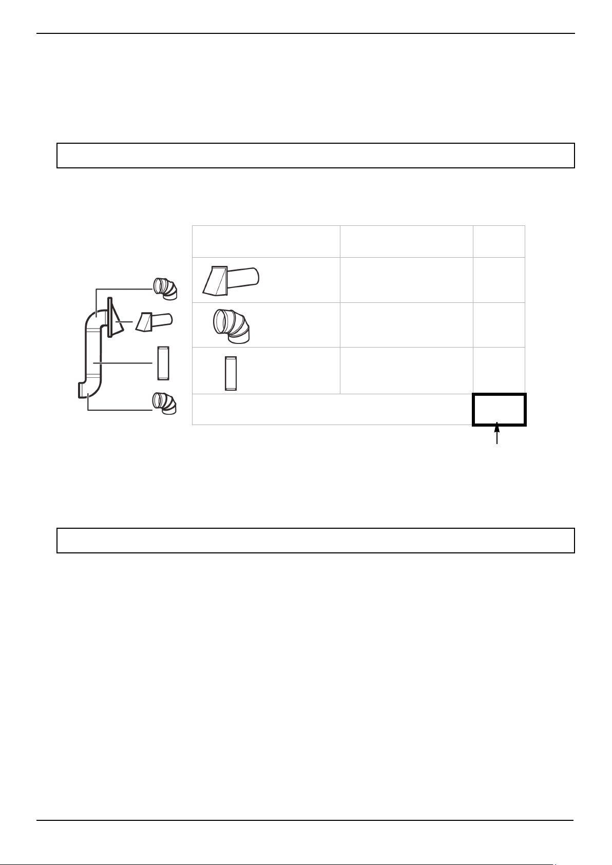
lengths of all the pieces together. For proper airflow, the equivalent airflow should not exceed 140 ft. For example:
Note: If a rectangular-to-round transition adapter is used, you must cut the bottom corners of the damper with tin snips to let the
damper have free movement.
Note: Equivalent lengths of duct pieces are based on actual tests and reflect requirements for good venting performance with any
vent hood.
EX
AMPLE
Duct Pieces Equivalent
Length
× Number
Used
= Total
Equivalent
Length
40 ft. ×
(
1 )
=
40 ft.
10 ft. ×
(
2 )
=
20 ft.
3 ft. ×
( 1 )
=
3 ft.
Total ductwork =
63 ft.
Roof cap
90° elbow
Straight duct 6” round
OR
3-1/4” × 10” rectangular
For proper airflow,
this number should
not exceed 140 ft.
Use the “Equivalent duct length table” on page 8 to calculate the equivalent ductwork length for your setup.
Example setup:
www.insigniaproducts.com
8
Equivalent duct length table
To calculate your equivalent duct length:
1 Write the number of sections used for each of the duct pieces.
2 Multiply the number used by the equivalent length for each duct piece.
3 Add the total equivalent lengths together. This number must be less than 140 ft.
Duct Pieces Equivalent
Length
× Number Used = Total
Equivalent
Length
5 ft. × ( ) = ft.
40 ft. × ( ) = ft.
10 ft. × ( ) = ft.
5 ft. × ( ) = ft.
25 ft. × ( ) = ft.
5 ft. × ( ) = ft.
24 ft. × ( ) = ft.
1 ft. × ( ) = ft.
Total ductwork =
ft.
(For proper airflow, this
number should not
exceed 140 ft.)
Rectangular-to-
round transition
adapter
Wall cap
90° elbow
45° elbow
90° elbow
45° elbow
Roof cap
Straight duct 6” round
OR
3-1/4” × 10” rectangular
www.insigniaproducts.com
9
NS-OTR16SS9 / NS-OTR16WH9
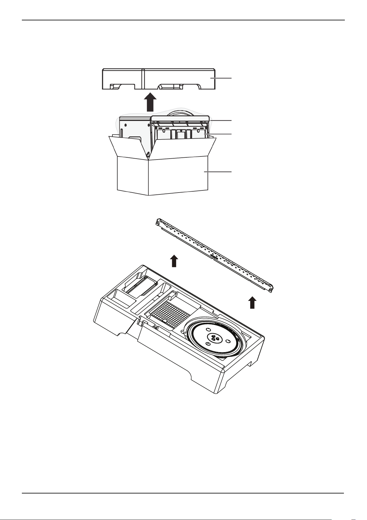
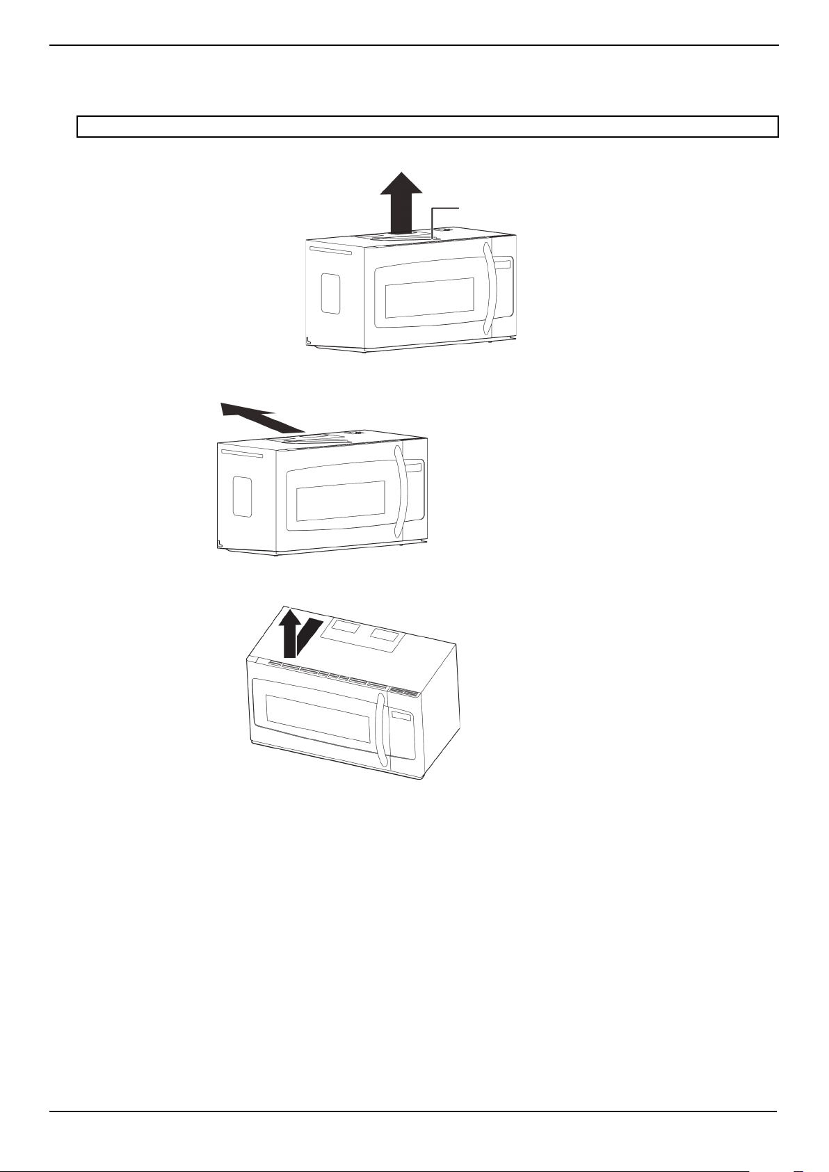
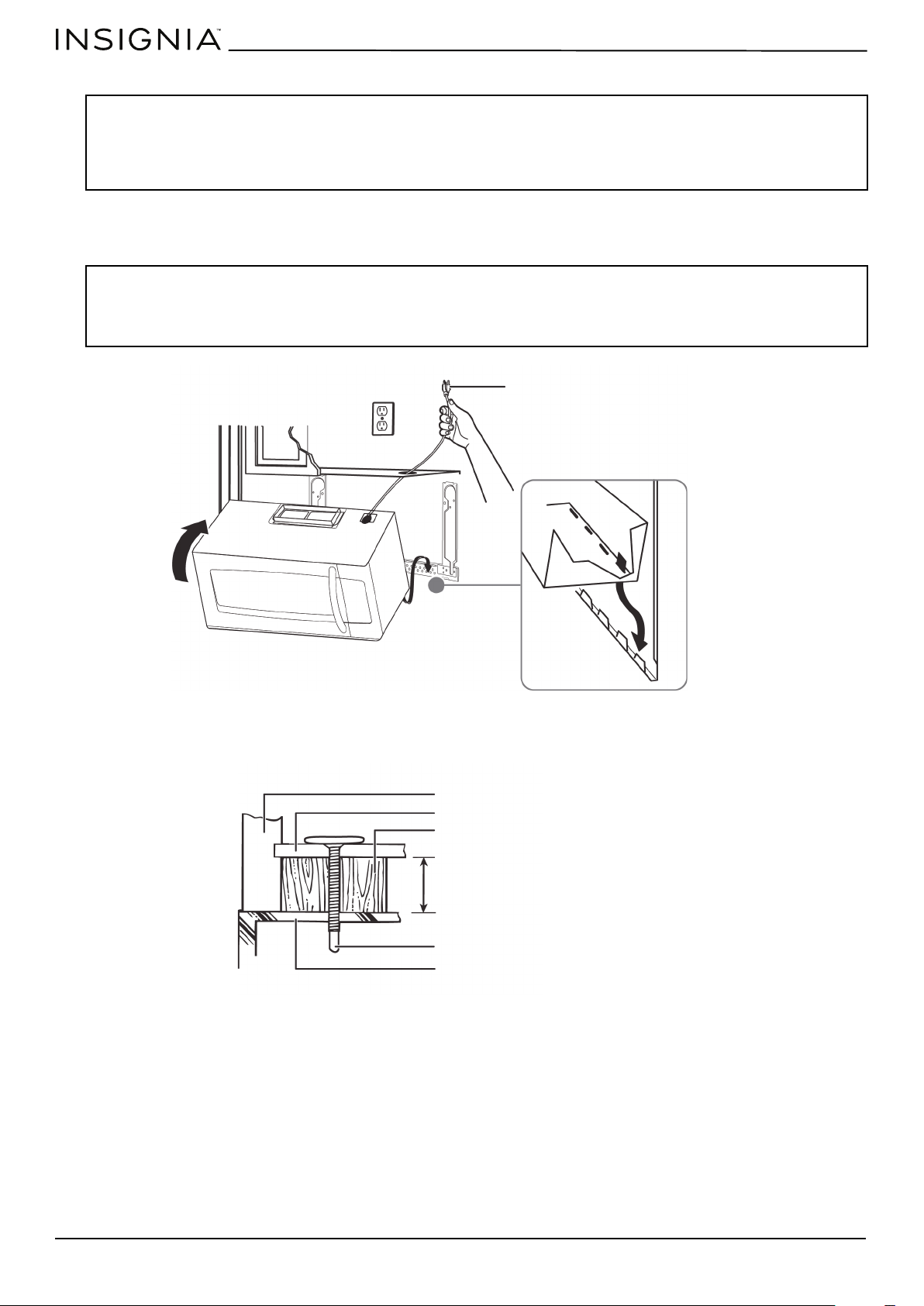
Removing your microwave
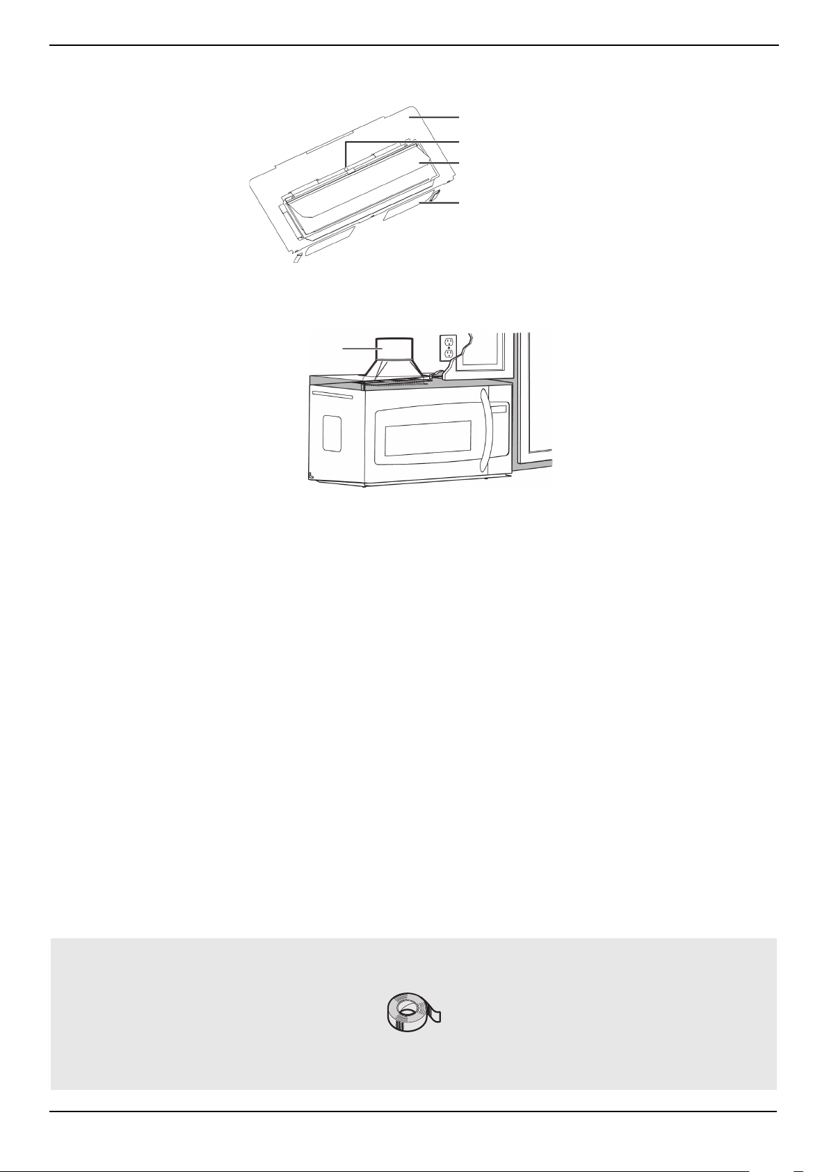
1 Remove the upper foam from the box. Keep all the accessories.
2 Pull the microwave out of the box.
3 Remove and throw away the plastic bags.
4 Remove the mounting plate from the upper foam.
Foam
Box
Microwave
Plastic bag
www.insigniaproducts.com
10
Installing your microwave
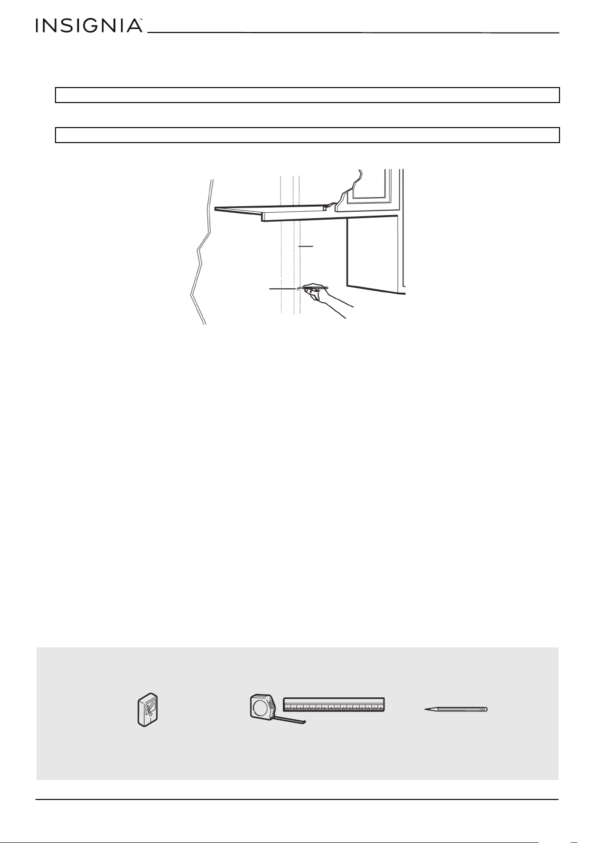
Step 1: Find the wall studs
1 Using an edge-to-edge stud finder, locate the edges of the wall stud(s) within the opening.
2 Mark the center of each stud, and then draw a vertical line down the center of each stud.
WARNING: Your microwave must be connected to at least one wall stud.
WARNING: The center of any adjacent wall studs should be 16" or 24" from this mark.
You’ll need:
Wall
stud
Center of the
wall stud
Pencil
Ruler or tape measure
Edge-to-edge stud finder
www.insigniaproducts.com
11
NS-OTR16SS9 / NS-OTR16WH9
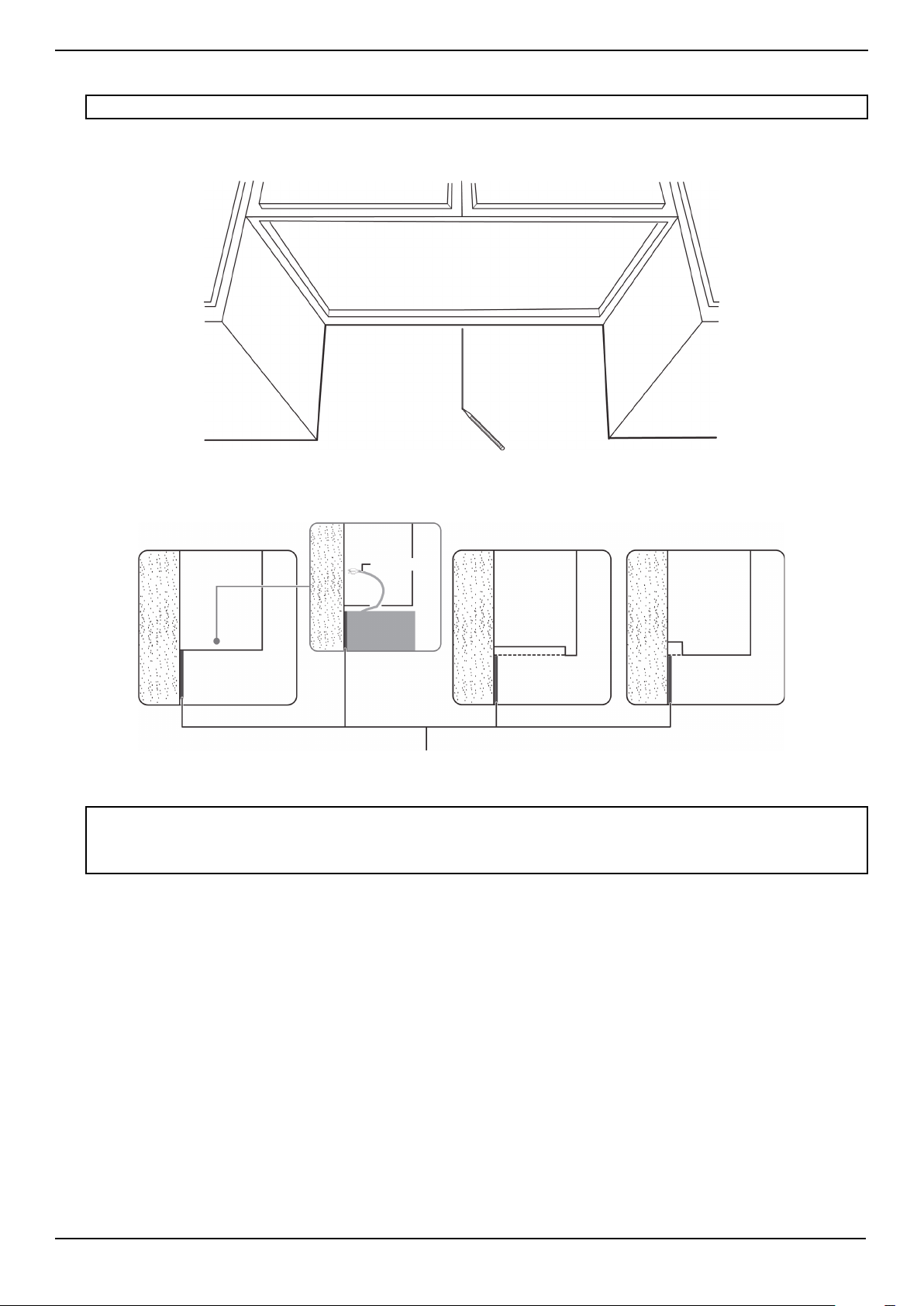
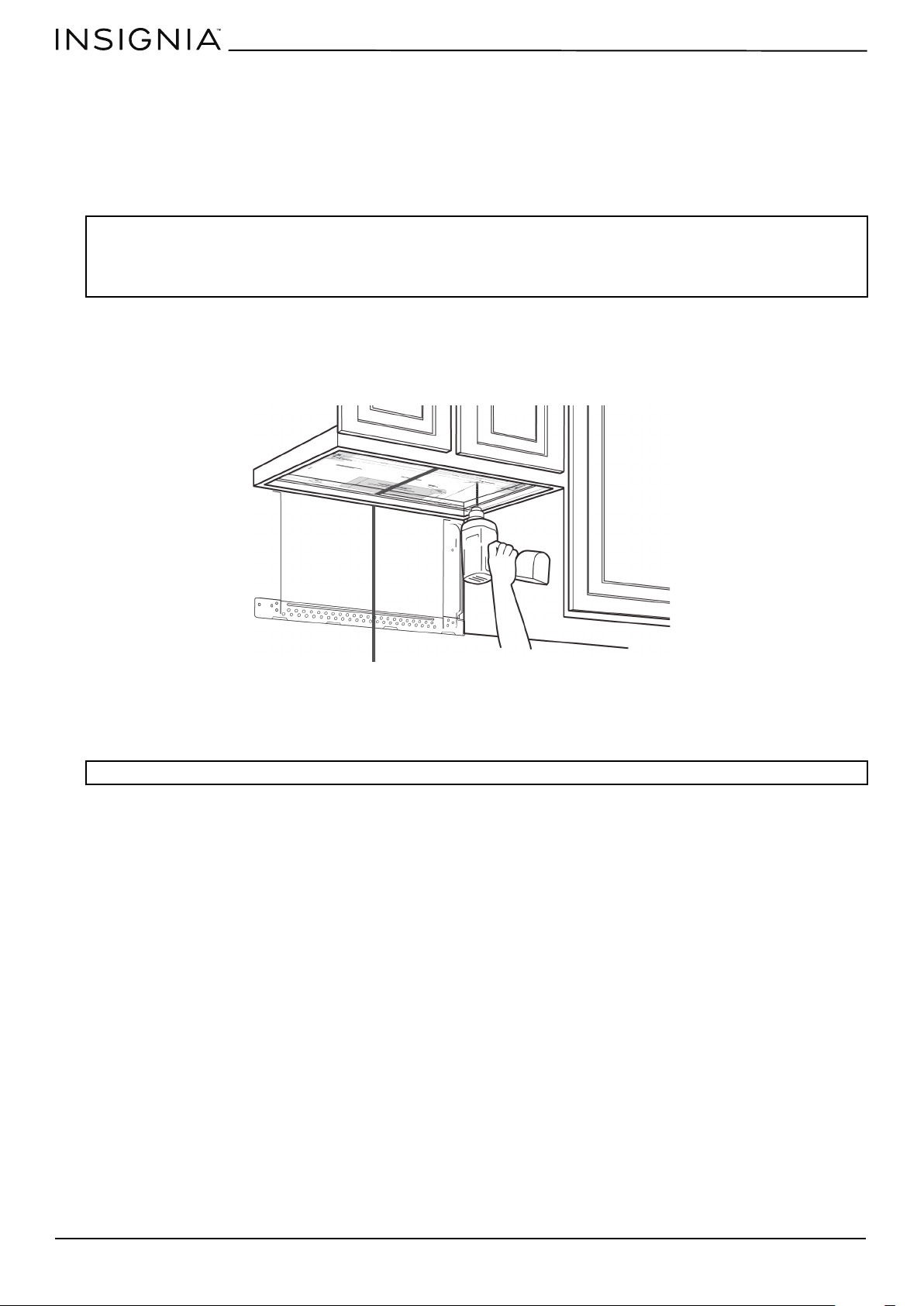
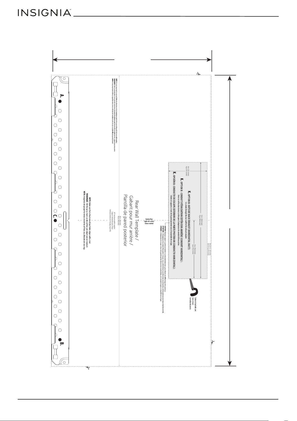
Step 2: Align the rear wall template
1 Use a level to make sure that the bottom of the cabinet is level.
2 Draw a vertical line down the center of the wall in the mounting space. This is where the center of your template will be.
3 Draw a horizontal line at the height of the front of your cabinet. This is where the top of your template will be. If the
bottom of your cabinet is flat, make sure that you leave space for the power cord.
4 Trim the rear wall template along the dotted line.
Note: If the rear wall template is damaged or unusable, measure and mark the wall with the dimensions at the end of this step.
Notes:
• If installing the microwave beneath smooth, flat cabinets, make sure that you leave enough space for the power cord clearance.
• If cabinets have decorative trim that interferes with the microwave installation, remove the trim to install the microwave properly
and to make sure that it is level.
Rear wall template
Power cord
Cabinet
Cabinet
Cabinet
Cabinet
W
ALL
W
ALL
W
ALL
Flat bottom:
Front overhang:
Recessed back:
www.insigniaproducts.com
12
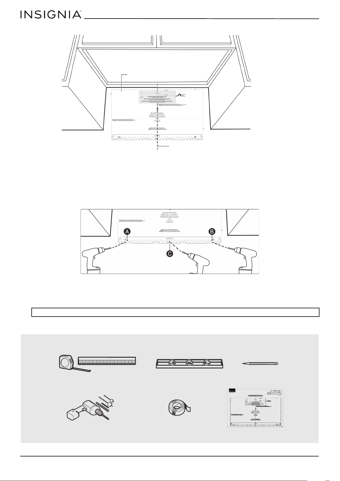
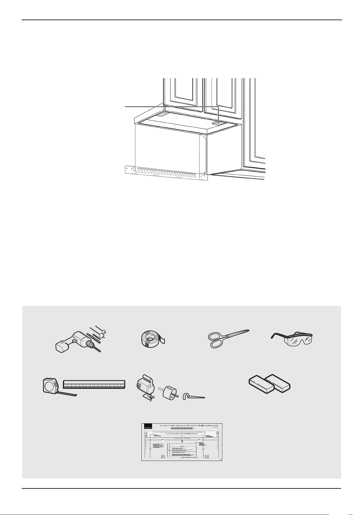
5 Tape the template in place so that it is centered on the vertical line and the top edge is aligned with the horizontal line.
6 Mark points A and B on the wall with a pencil.
7 If the stud is on the center line, mark point C on the wall with a pencil.
OR
If the stud is not on the center line, mark two holes on either side of point C that align with the studs.
8 Drill holes through the template at points you marked. If the hole lines up with a stud, drill a 3/16” hole. Otherwise, drill
a 5/8" hole for the toggle bolts.
Note: At least three holes must be used for mounting.
You’ll need:
Vertical line in the center
Top of the template aligned
with the horizontal line
Note: Depending on your stud locations, your installation may look
different. You should mount to at least one stud.
Rear wall template
Pencil
Duct tape
Electric drill with 3/16” and 5/8” bits
Level
Ruler or tape measure
www.insigniaproducts.com
13
NS-OTR16SS9 / NS-OTR16WH9
Step 3: Select a ventilation type
This microwave is designed for three types of ventilation. Select the type of ventilation you want to use, then go to the
corresponding page.
Option A - Outside top exhaust (vertical duct): See page 14
Option B - Outside back exhaust (horizontal duct): See page 22
Option C - Recirculating (non-vented/ductless): See page 32
Note: This microwave is shipped assembled for top exhaust ventilation.
Adapter
Note: If a wall stud is within
6 in. (15.2 cm) of the vertical
center line, you cannot use
this installation option.
*Requires a
charcoal filter
(included)
www.insigniaproducts.com
14
Step 4: Option A - Attach the mounting plate to the wall
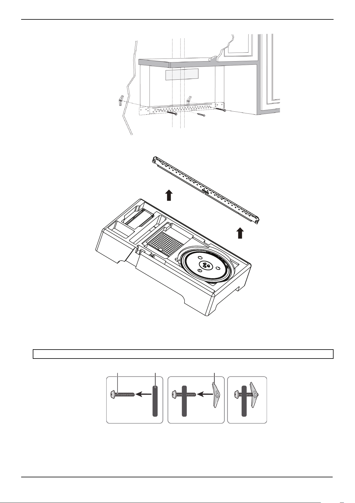
1 Remove the rear wall template.
2 Remove the mounting plate from the upper foam.
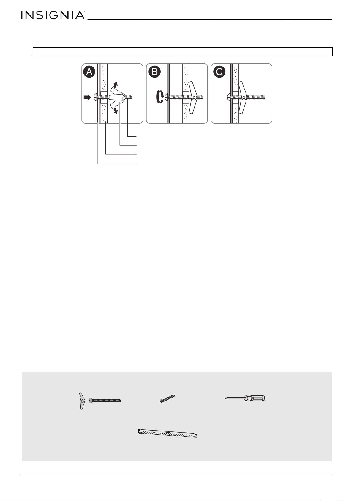
3 Insert the toggle bolt(s) through the front of the mounting plate into the hole(s) that are not going into a stud, and
then attach the toggle wings ¾" onto each bolt. Hold your mounting plate up to holes in your wall to identify the
correct position.
4 Place the mounting plate against the wall and insert the toggle wings into the holes you drilled in the drywall. Pull the
mounting plate away from the wall to help tighten the toggle wings.
Note: The top of the mounting plate is indicated with an arrow. The mounting plate’s hooks are on the front.
Note: Depending on
your stud locations,
your installation may
look different. You
should insert toggle
bolts into drywall and
wood screws into
studs.
Bolt
Wing
Mounting plate

www.insigniaproducts.com
15
NS-OTR16SS9 / NS-OTR16WH9
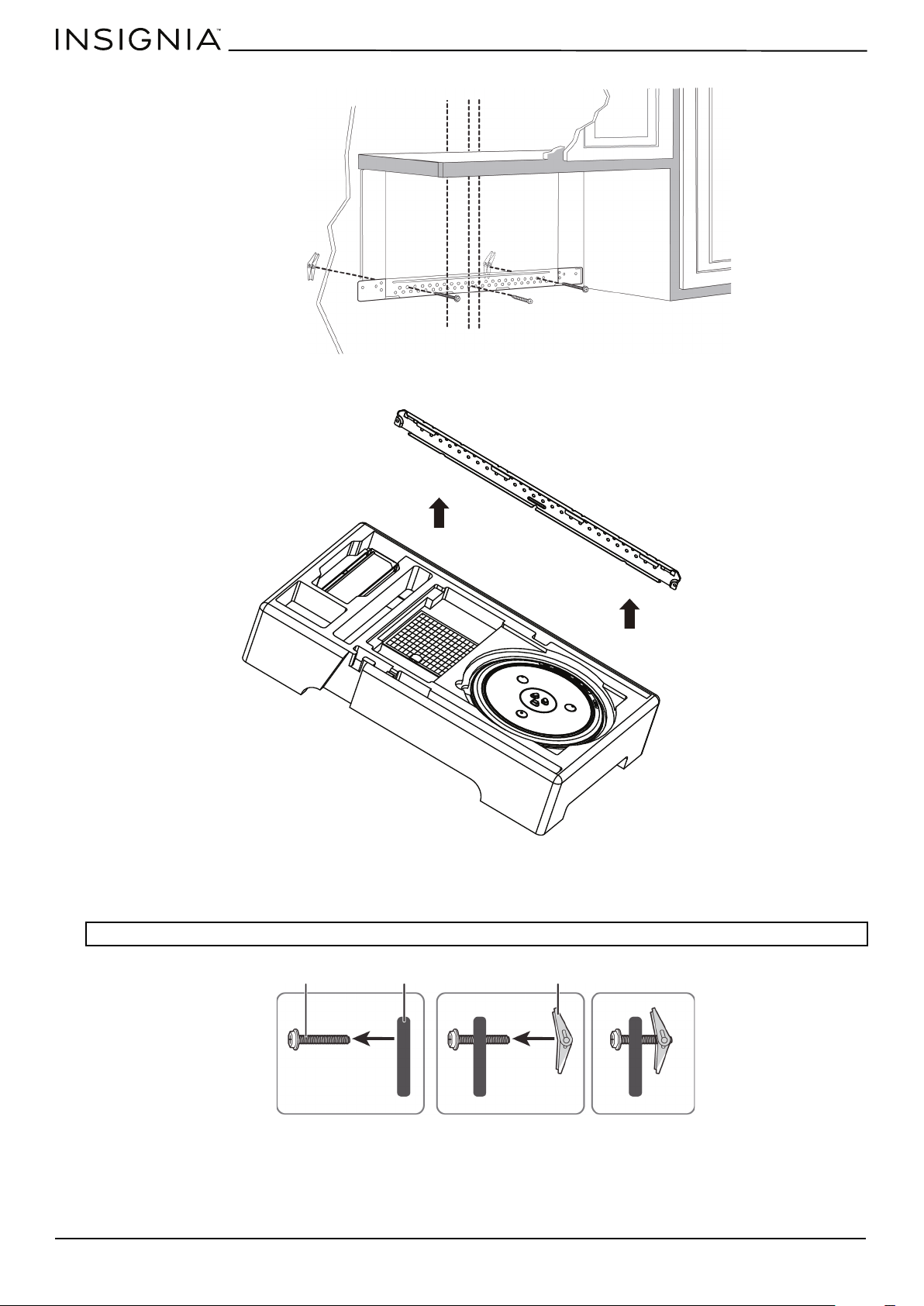
5 Insert wood screw(s) through the mounting plate and into the hole(s) drilled in the stud(s), then tighten both the wood
screw(s) and toggle bolt(s) with a Phillips screwdriver to mount the plate. Make sure that the plate is centered before
tightening fully.
CAUTION: Be careful to avoid pinching your fingers between the back of the mounting plate and the wall.
You’ll need:
Mounting plate
Wall
Toggle wing
Toggle bolt
Wood screws
Mounting plate (Qty. 1)
Toggle bolts
Phillips screwdrivers
www.insigniaproducts.com
16
Step 5: Option A - Preparing the top cabinet
You need to drill holes for the top support screws, a hole large enough for the power cord to fit through, and a cutout large
enough for the exhaust adapter.
1 Turn off the power to the outlet in the cabinet.
2 Remove everything from the cabinet.
3 Trim the Top Cabinet Template along the dotted line.
4 If the bottom of your cabinet is recessed and the template is too large, trim the edges to fit. Your template should fit
snugly inside the space with no overhang.
5 To position the Top Cabinet Template:
• Align the center line on the template with the center line that you drew on the wall.
• Align the back edge of the template to the rear wall (smooth or flat bottom cabinets) or to the back of the recess
(recessed cabinets) to make sure that the holes cut into the upper cabinet align with the holes in the top of the
microwave.
6 Tape the template to the bottom of the cabinet.
7 Drill ½" holes through the template at points D and E.
8 Cut a 2" diameter hole at point F for the power cord.
9 Cut out the shaded area I through the cabinet bottom.
10 Remove the template.
Notes:
• Make sure that you keep the left and right sides even. For example, if you need to trim the sides by 1", cut 1/2" from the left side and
1/2" from the right side.
• Some cabinets have a small bracket or glue block between the overhang and the underside of the cabinet bottom. Cut the template
to fit around these so it lies flat on the bottom of the cabinet.
CAUTION: Wear safety goggles when drilling holes in the cabinet bottom.
Center line
www.insigniaproducts.com
17
NS-OTR16SS9 / NS-OTR16WH9
11 If you have recessed cabinets:
• Make two filler blocks out of scrap wood pieces the size of shaded areas G and H. They must be as thick as the depth
of the cabinet recess.
• Drill 5/8" holes in the filler blocks to align with points D and E.
• Align the blocks with the corresponding holes in the cabinet. They should be at the same level as the bottom edge of
the cabinet frame.
You’ll need:
Filler blocks
Electric drill with 1/2” and
5/8” bits
Duct tape
Scissors
(recessed cabinets only)
Safety goggles
Saw
(saber, hole, or keyhole)
Ruler or tape measure
Filler blocks or scrap wood pieces
(for recessed cabinets only)
Top Cabinet Template
www.insigniaproducts.com
18
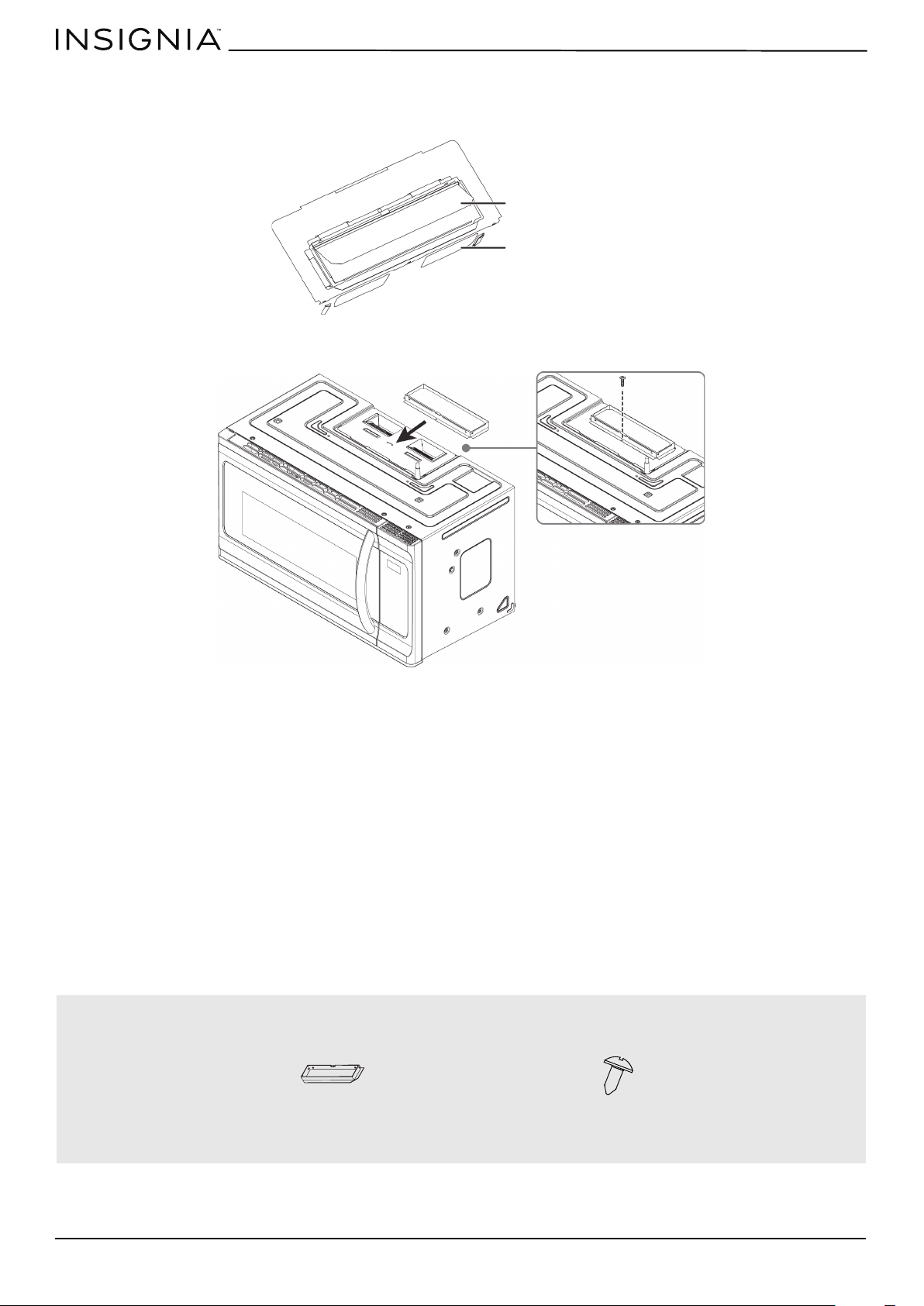
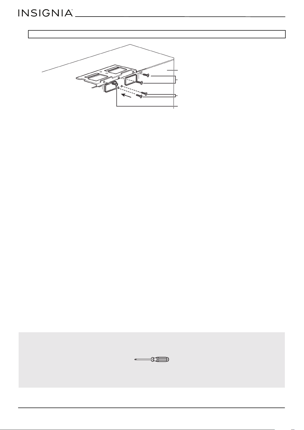
Step 6: Option A - Insert the exhaust adapter
1 Set the microwave in its upright position, with the top facing up.
2 Remove any tape securing the damper and make sure that the damper pivots easily.
3 Insert the exhaust adapter into the slots next to the ventilation and secure with a sheet metal screw.
You’ll need:
Damper
Back of microwave
Sheet metal screw
Exhaust adapter
www.insigniaproducts.com
19
NS-OTR16SS9 / NS-OTR16WH9
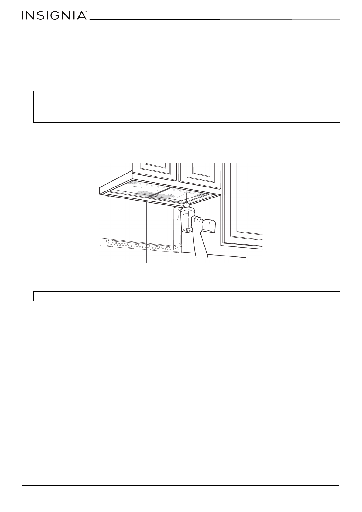
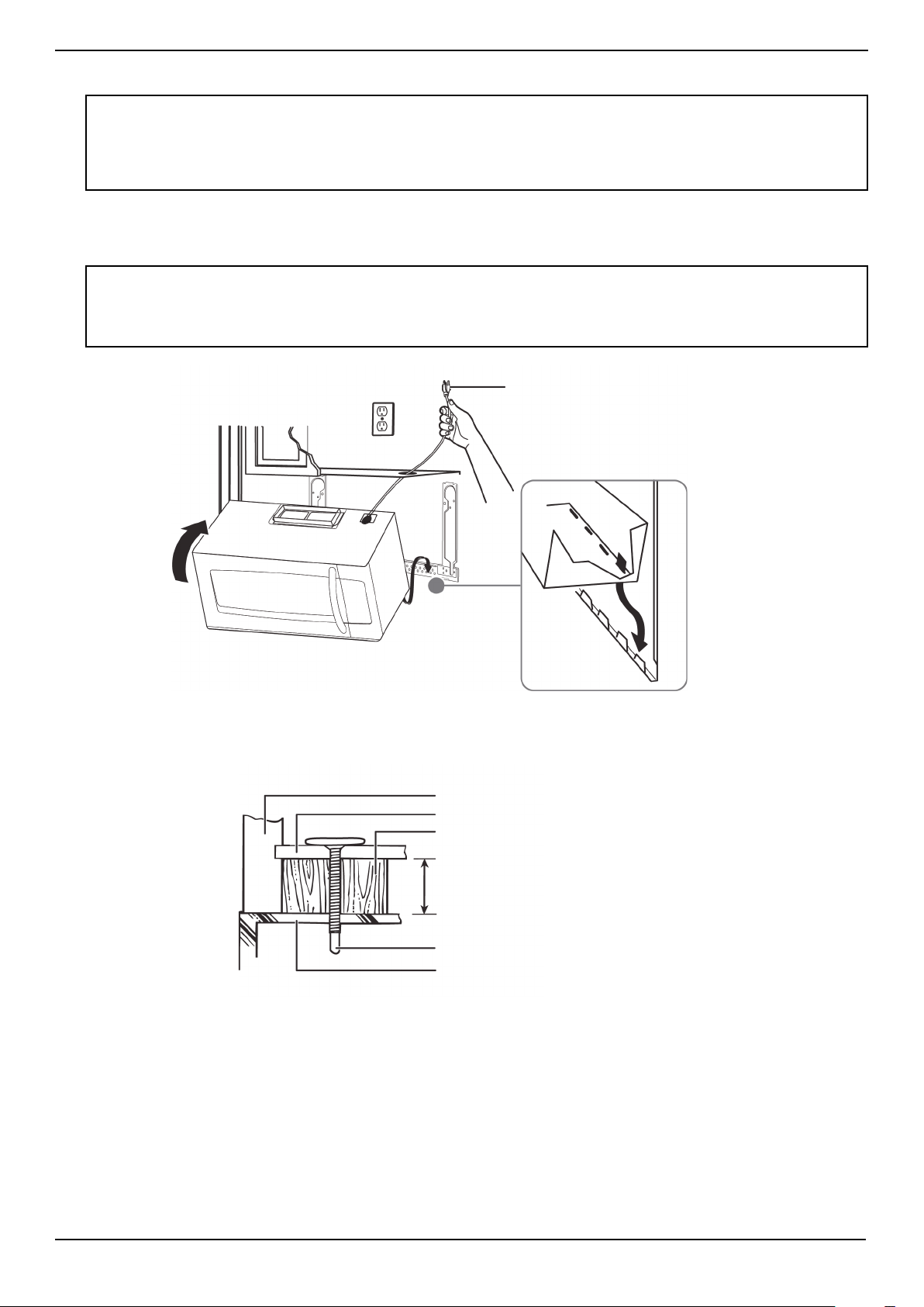
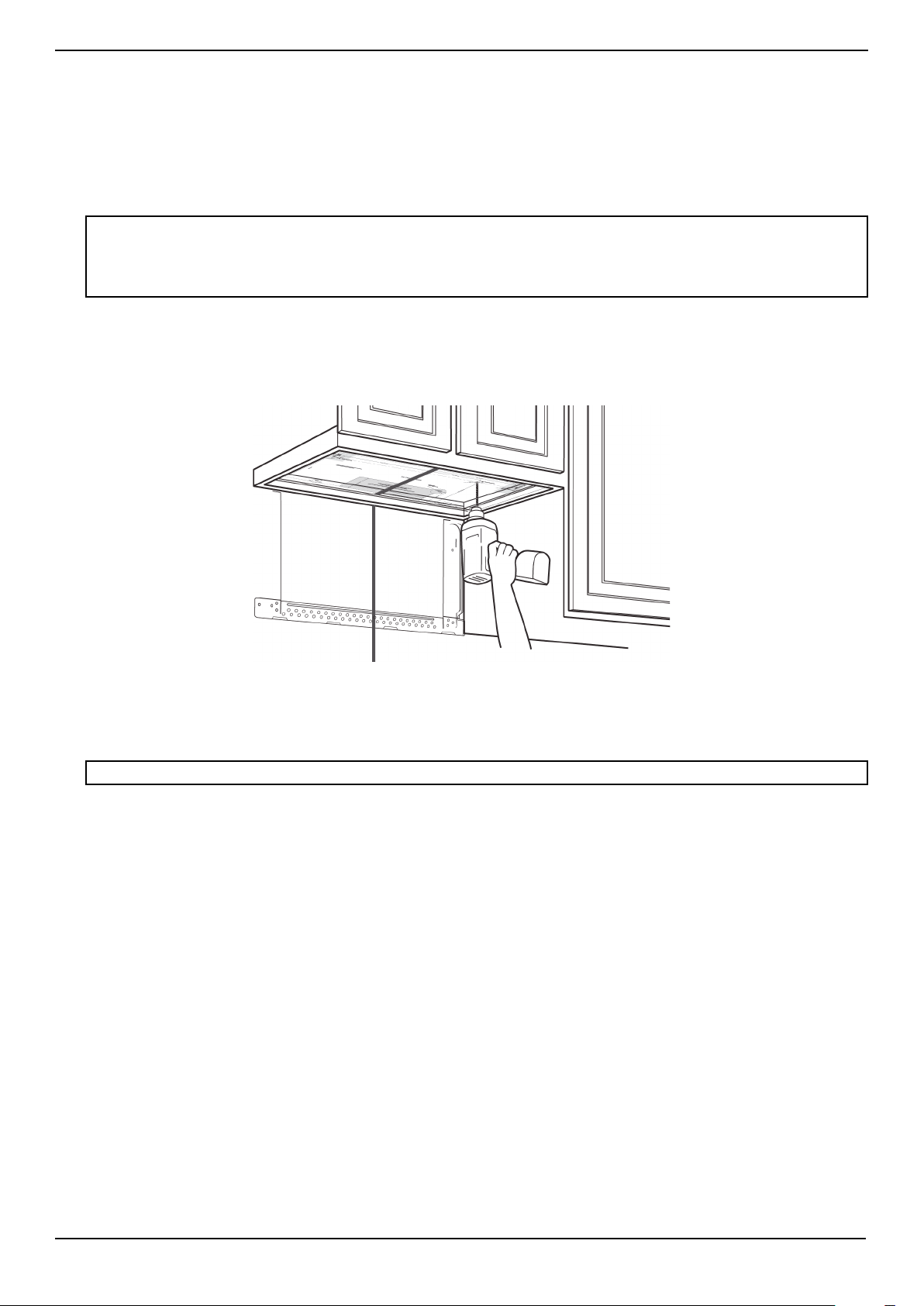
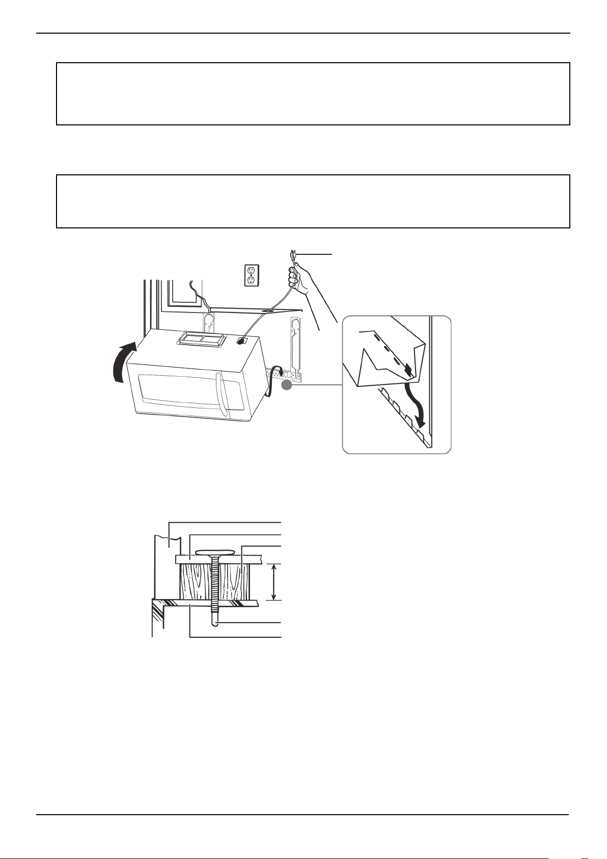
Step 7: Option A - Mount the microwave
1 If your cabinet is metal, insert the nylon grommet into the power cord hole to prevent cutting the cord.
2 Lift the microwave, tilt it forward, and hook the slots on the back bottom edge onto the four lower tabs of the
mounting plate. Rotate the front of the microwave up against the bottom of the cabinet.
3 To attach the microwave oven to the top cabinet, insert two self-aligning machine screws through the holes you drilled
in the bottom of the cabinet. Turn each screw at least two full turns (they will be fully tightened later).
CAUTIONS:
• For easier installation and personal safety, we recommend that two people install this product because of the weight. We highly
recommend professional installation if any electrical or carpentry work is required.
• Do not grip or use the handle during installation.
• To keep the power cord tight while mounting the microwave oven, thread the power cord through the hole in the bottom of the
cabinet.
Notes:
• We recommend using filler blocks if the front of the cabinet hangs below the cabinet’s bottom shelf.
• If filler blocks are not used, damage may occur from over-tightening the screws.
• Be sure to keep the power cord tight.
• Do not pinch the cord, especially when mounting flush to the bottom of the cabinet.
Thread the power cord through the
cable hole in the top cabinet. Keep it
tight throughout steps 1-2.
Front of cabinet
Bottom of cabinet
Filler block (optional)
Self-aligning machine screw
Top of microwave
Equivalent to depth of cabinet recess
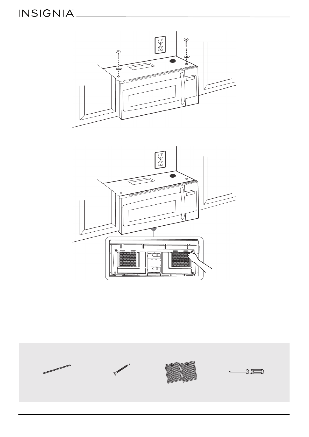
www.insigniaproducts.com
20
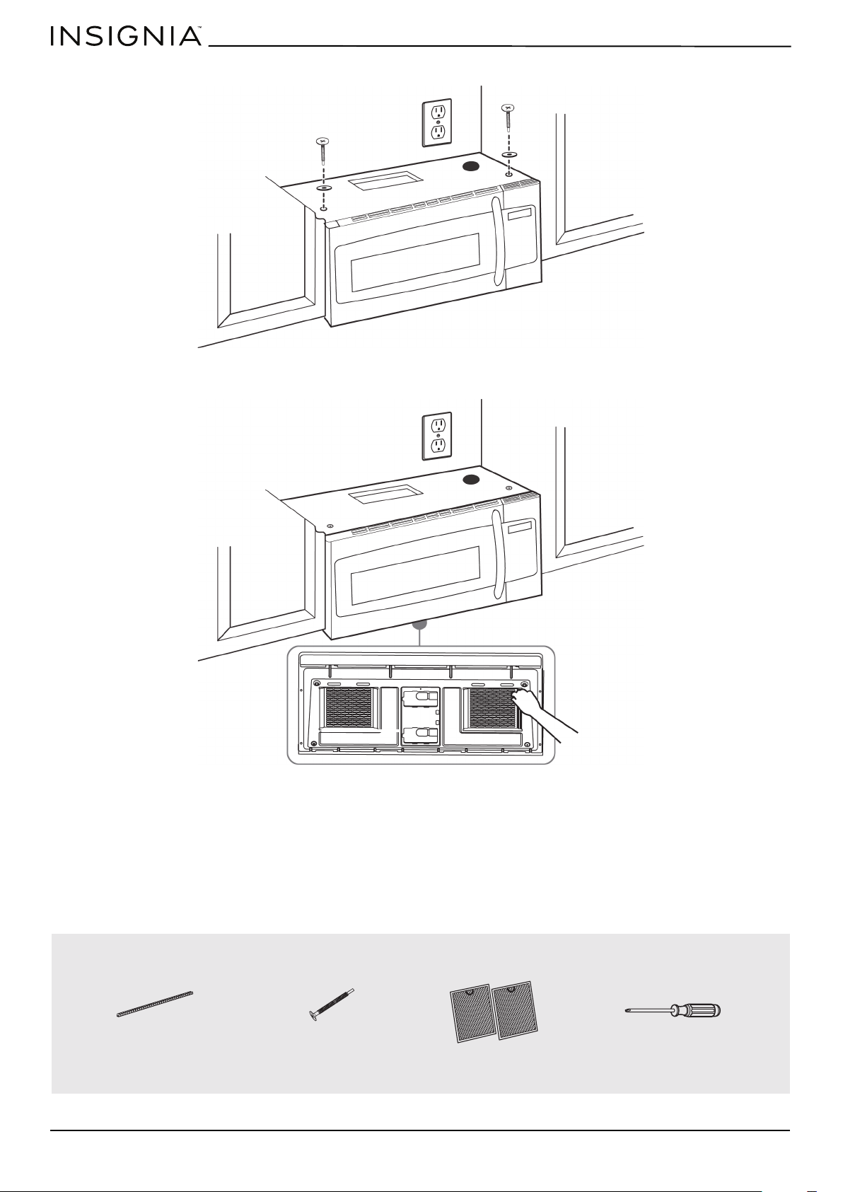
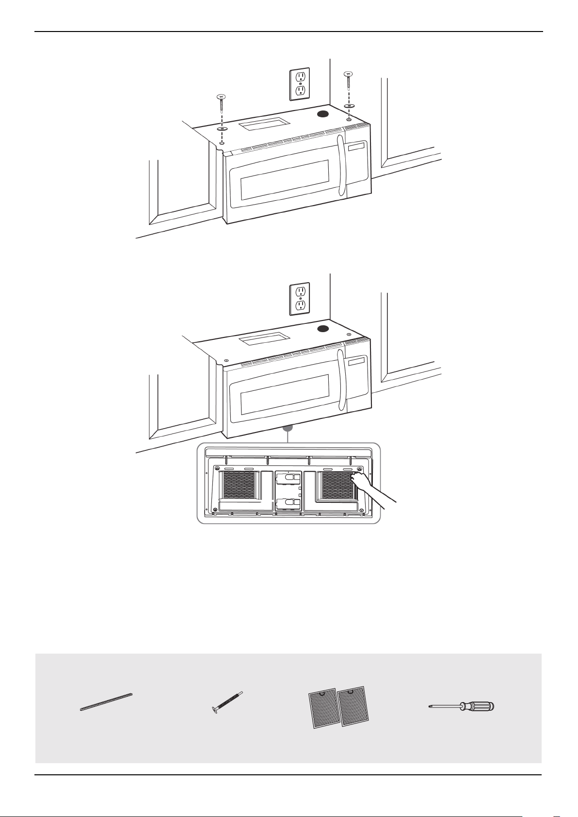
4 While holding the microwave up against the wall and cabinet fully tighten the outer two screws.
5 Fit the two grease filters into the openings underneath your microwave.
You’ll need:
BOTTOM
Nylon grommet
(for metal cabinets)
Self-aligning machine
screws
Grease filters
Phillips screwdrivers
www.insigniaproducts.com
21
NS-OTR16SS9 / NS-OTR16WH9
Step 8: Option A - Connecting ductwork
1 Open the cabinet and slide the exhaust adapter front-to-back or side-to-side to adjust.
2 Extend the house duct down to connect to the exhaust adapter.
3 Seal the exhaust duct joints with duct tape.
4 You’re finished! Skip to “Before using your microwave” on page 41.
You’ll need:
Blower plate
Exhuast adapter
Damper
Back of microwave
House duct
Duct tape

www.insigniaproducts.com
22
Step 4: Option B - Cutting a vent opening
1 Use a saber or keyhole saw to cut out the shaded area K through the rear wall.
2 Remove the rear wall template.
Note: If a wall stud is within 6 in. (15.2 cm) of the vertical center line, you cannot use this installation option.
You’ll need:
Saw
Saw
(saber, hole, or keyhole)
www.insigniaproducts.com
23
NS-OTR16SS9 / NS-OTR16WH9
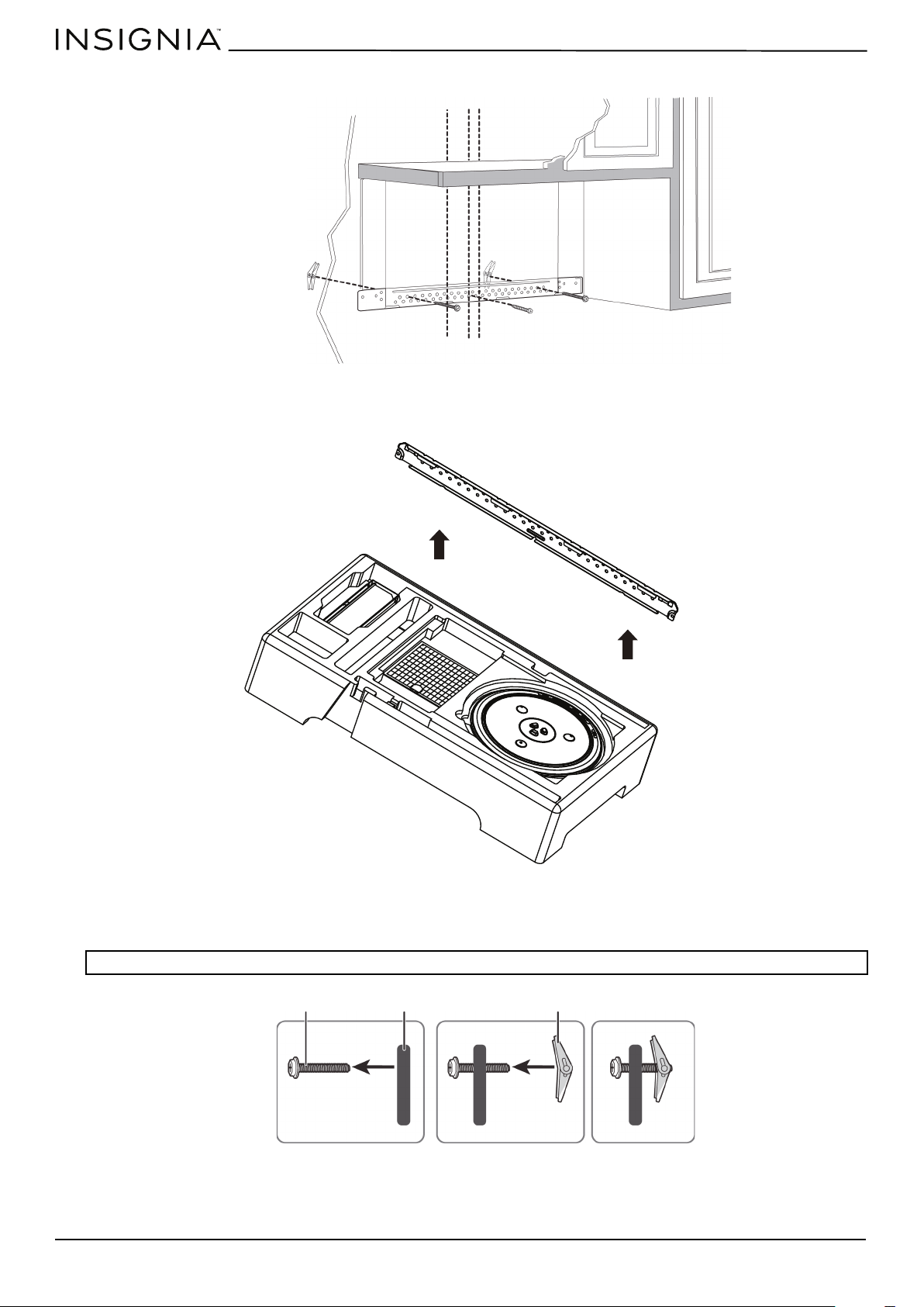
Step 5: Option B - Attach the mounting plate to the wall
1 Remove the rear wall template.
2 Remove the mounting plate from the upper foam.
3 Insert the bolt(s) through the front of the mounting plate into the hole(s) that are not going into a stud, and then
reattach the toggle wings ¾" onto each bolt. Hold your mounting plate up to holes in your wall to identify the correct
position.
4 Place the mounting plate against the wall and insert the toggle wings into the holes you drilled in the drywall. Pull the
mounting plate away from the wall to help tighten the toggle wings.
Note: The top of the mounting plate is indicated with an arrow. The mounting plate’s hooks are on the front.
Note: Depending on
your stud locations,
your installation may
look different. You
should insert toggle
bolts into drywall and
wood screws into
studs.
Bolt
Wing
Mounting plate
www.insigniaproducts.com
24
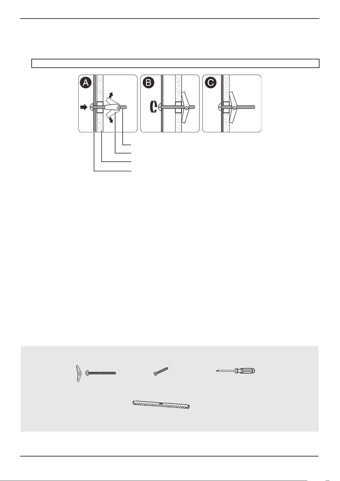
5 Insert wood screw(s) through the mounting plate and into the hole(s) drilled in the stud(s), then tighten both the wood
screw(s) and toggle bolt(s) with a Phillips screwdriver to mount the plate. Make sure that the plate is centered before
tightening fully.
CAUTION: Be careful to avoid pinching your fingers between the back of the mounting plate and the wall.
You’ll need:
Mounting plate
Wall
Toggle wing
Toggle bolt
Wood screws
Mounting plate (Qty. 1)
Phillips screwdrivers
Toggle bolts
www.insigniaproducts.com
25
NS-OTR16SS9 / NS-OTR16WH9
Step 6: Option B - Preparing the top cabinet
You need to drill holes for the top support screws and a hole large enough for the power cord to fit through.
1 Turn off the power to the outlet in the cabinet.
2 Remove everything from the cabinet.
3 Trim the Top Cabinet Template along the dotted line.
4 If the bottom of your cabinet is recessed and the template is too large, trim the edges to fit. Your template should fit
snugly inside the space with no overhang.
5 To position the Top Cabinet Template:
• Align the center line on the template with the center line that you drew on the wall.
• Align the back edge of the template to the rear wall (smooth or flat bottom cabinets) or to the back of the recess
(recessed cabinets) to make sure that the holes cut into the upper cabinet align with the holes in the top of the
microwave.
6 Tape the template to the bottom of the cabinet.
7 Drill ½" holes through the template at points D and E.
8 Cut a 2" diameter hole at point F for the power cord.
9 Remove the template.
Notes:
• Make sure that you keep the left and right sides even. For example, if you need to trim the sides by 1", cut 1/2" from the left side and
1/2" from the right side.
• Some cabinets have a small bracket or glue block between the overhang and the underside of the cabinet bottom. Cut the
template to fit around these so it lies flat on the bottom of the cabinet.
CAUTION: Wear safety goggles when drilling holes in the cabinet bottom.
Center line
www.insigniaproducts.com
26
10 If you have recessed cabinets:
• Make two filler blocks out of scrap wood pieces the size of shaded areas G and H. They must be as thick as the depth
of the cabinet recess.
• Drill 5/8" holes in the filler blocks to align with points D and E.
• Align the blocks with the corresponding holes in the cabinet. They should be at the same level as the bottom edge of
the cabinet frame.
You’ll need:
Filler blocks
Top Cabinet Template
Electric drill with 1/2” and
5/8” bits
Duct tape
Scissors
(recessed cabinets only)
Safety goggles
Saw
(saber, hole, or keyhole)
Ruler or tape measure
Filler blocks or scrap wood pieces
(for recessed cabinets only)
www.insigniaproducts.com
27
NS-OTR16SS9 / NS-OTR16WH9
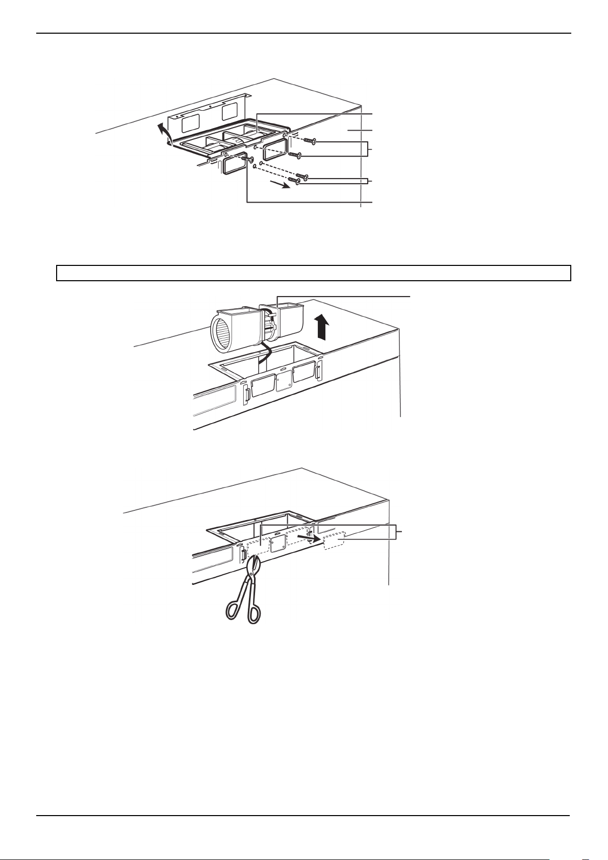
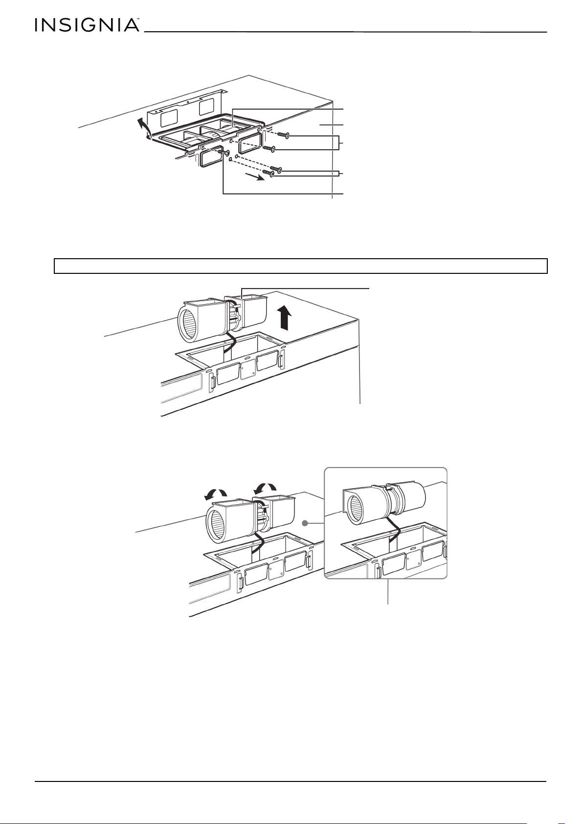
Step 7: Option B - Adapt the microwave blower for outside back exhaust
1 Remove and save the five screws that hold the blower unit in the microwave.
2 Carefully pull out the blower unit. The wires will extend far enough to let you adjust the blower unit. Do not disconnect
the wires.
3 Cut out the vent holes with tin snips.
WARNING: Do not pull or stretch the blower unit wiring. Make sure that the wires are not pinched.
Blower plate and adapter
screws
Blower motor screw
Back of microwave
Blower unit
Blower plate and adapter screw
Blower unit
Vent hole covers
www.insigniaproducts.com
28
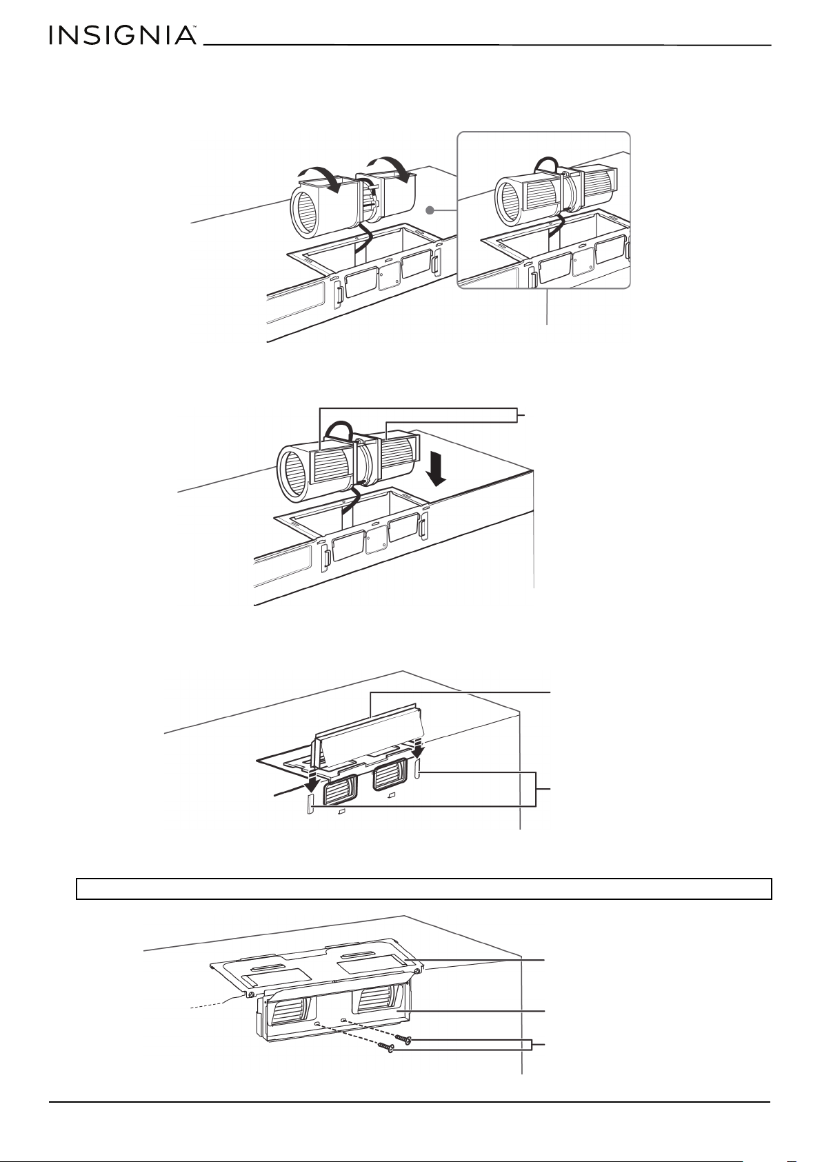
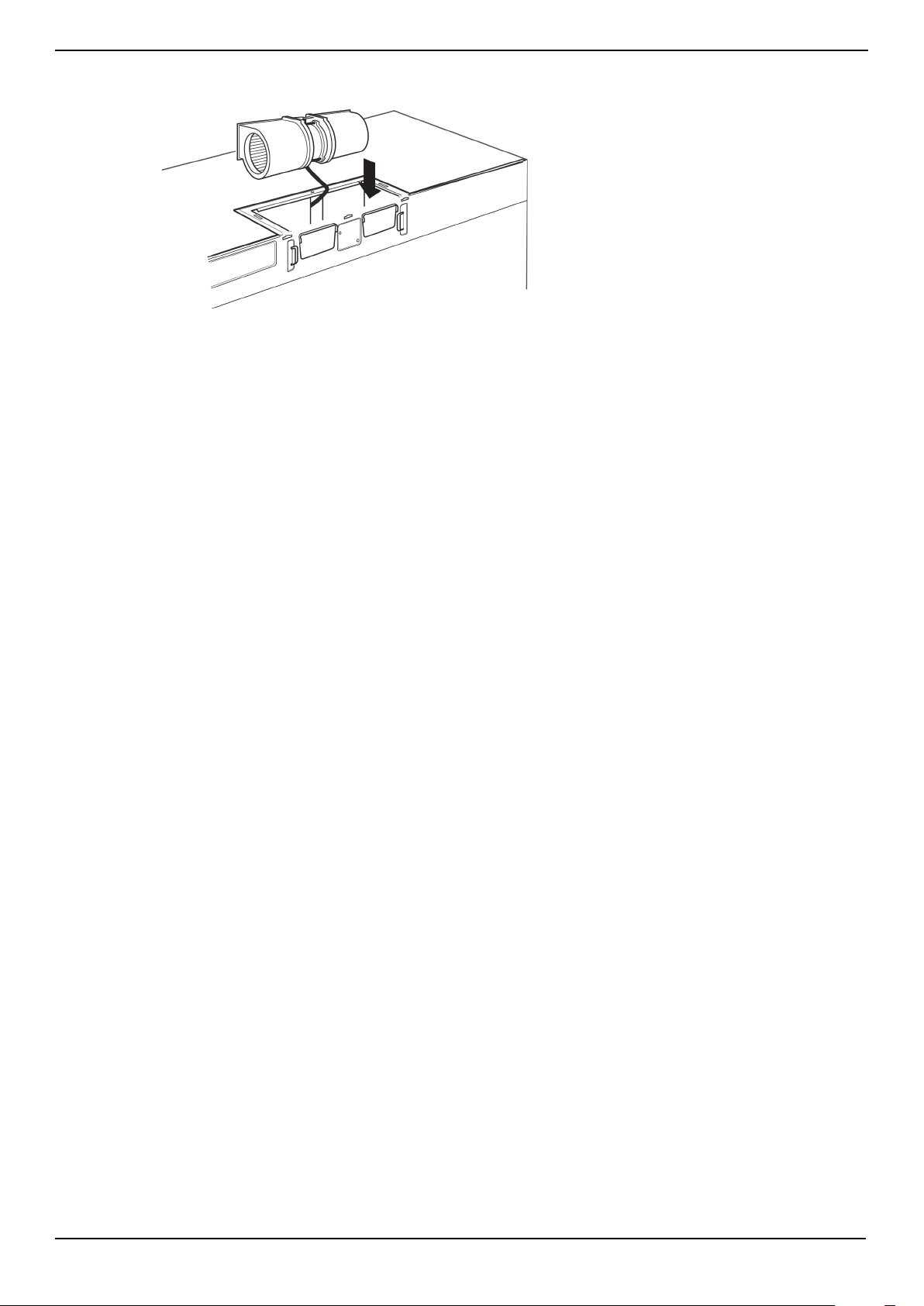
4 Turn the blower unit 180° so that the fan blade openings are facing out the back of the microwave.
5 Place the blower unit back into the opening. The blower unit exhaust openings should match the exhaust openings on
back of the microwave.
6 Slide the exhaust adapter into the guides on the back of the microwave and push in until it is aligned with the blower
motor screw holes, then secure with the blower motor screws.
7 Secure the blower unit in the microwave with two of the screws you previously removed.
.
Note: Make sure that the damper hinge is at the top and that it can swing freely.
BEFORE
AFTER
Fan blade openings
facing the back
Exhaust adapter
Guides
Blower motor screw
Exhaust adapter
Blower plate
www.insigniaproducts.com
29
NS-OTR16SS9 / NS-OTR16WH9
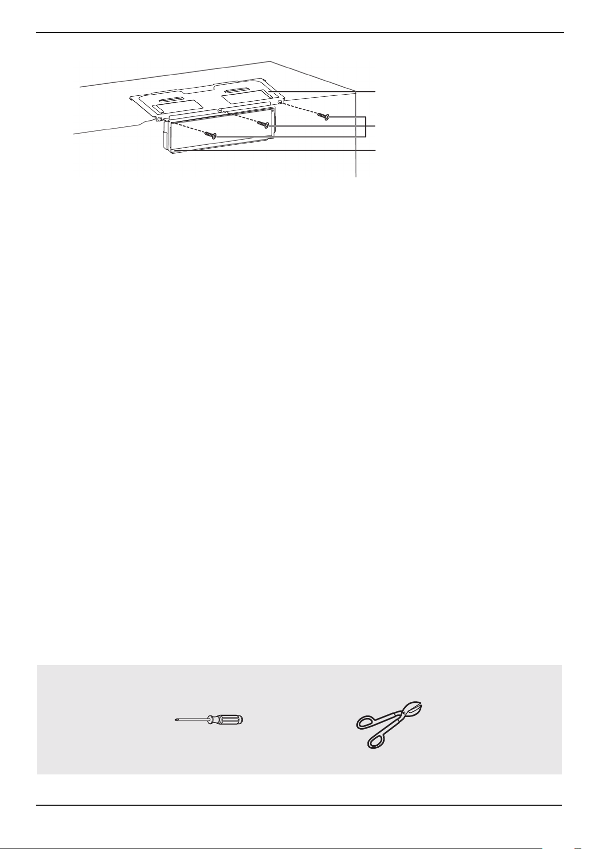
8 Secure the blower plate and exhaust adapter with the remaining screws you removed previously.
You’ll need:
Blower plate and adapter screws
Exhaust adapter
Blower plate
Phillips screwdrivers
Tin snips
www.insigniaproducts.com
30
Step 8: Option B - Mount the microwave
1 If your cabinet is metal, insert the nylon grommet into the power cord hole to prevent cutting the cord.
2 Lift the microwave, tilt it forward, and hook the slots on the back bottom edge onto the four lower tabs of the
mounting plate. Rotate the front of the microwave up against the bottom of the cabinet.
3 To attach the microwave oven to the top cabinet, insert two self-aligning machine screws through the holes you drilled
in the bottom of the cabinet. Turn each screw at least two full turns (they will be fully tightened later).
CAUTIONS:
• For easier installation and personal safety, we recommend that two people install this product because of the weight. We highly
recommend professional installation if any electrical or carpentry work is required.
• Do not grip or use the handle during installation.
• To keep the power cord tight while mounting the microwave oven, thread the power cord through the hole in the bottom of the top
cabinet.
Notes:
• We recommend using filler blocks if the front of the cabinet hangs below the cabinet’s bottom shelf.
• If filler blocks are not used, damage may occur from over-tightening the screws.
• Be sure to keep the power cord tight.
• Do not pinch the cord, especially when mounting flush to the bottom of the cabinet.
Thread the power cord through the
cable hole in the top cabinet. Keep it
tight throughout steps 1-2.
Front of cabinet
Bottom of cabinet
Filler block (optional)
Self-aligning machine screw
Top of microwave
Equivalent to depth of cabinet recess
www.insigniaproducts.com
31
NS-OTR16SS9 / NS-OTR16WH9
4 While holding the microwave up against the wall and cabinet fully tighten the outer two screws.
5 Fit the two grease filters into the openings underneath your microwave.
6 You’re finished! See “Before using your microwave” on page 41
You’ll need:
BOTTOM
Nylon grommet
(for metal cabinets)
Self-aligning machine
screws
Grease filters
Phillips screwdrivers
www.insigniaproducts.com
32
Step 4: Option C - Attach the mounting plate to the wall
1 Remove the rear wall template.
2 Remove the mounting plate from the upper foam.
3 Insert the bolt(s) through the front of the mounting plate into the hole(s) that are not going into a stud, and then
reattach the toggle wings ¾" onto each bolt. Hold your mounting plate up to holes in your wall to identify the correct
position.
Note: The top of the mounting plate is indicated with an arrow. The mounting plate’s hooks are on the front.
Note: Depending on
your stud locations,
your installation may
look different. You
should insert toggle
bolts into drywall and
wood screws into
studs.
Bolt
Wing
Mounting plate
www.insigniaproducts.com
33
NS-OTR16SS9 / NS-OTR16WH9
4 Place the mounting plate against the wall and insert the toggle wings into the holes you drilled in the drywall. Pull the
mounting plate away from the wall to help tighten the toggle wings.
5 Insert wood screw(s) through the mounting plate and into the hole(s) drilled in the stud(s), then tighten both the wood
screw(s) and toggle bolt(s) with a Phillips screwdriver to mount the plate. Make sure that the plate is centered before
tightening fully.
Note: Be careful to avoid pinching your fingers between the back of the mounting plate and the wall.
You’ll need:
Mounting plate
Wall
Toggle wing
Toggle bolt
Wood screws
Mounting plate (Qty. 1)
Phillips screwdrivers
Toggle bolts
www.insigniaproducts.com
34
Step 5: Option C - Preparing the top cabinet
You need to drill holes for the top support screws and a hole large enough for the power cord to fit through.
1 Turn off the power to the outlet in the cabinet.
2 Remove everything from the cabinet.
3 Trim the Top Cabinet Template along the dotted line.
4 If the bottom of your cabinet is recessed and the template is too large, trim the edges to fit. Your template should fit
snugly inside the space with no overhang.
5 To position the Top Cabinet Template:
• Align the center line on the template with the center line that you drew on the wall.
• Align the back edge of the template to the rear wall (smooth or flat bottom cabinets) or to the back of the recess
(recessed cabinets) to make sure that the holes cut into the upper cabinet align with the holes in the top of the
microwave.
6 Tape the template to the bottom of the cabinet.
7 Drill ½" holes through the template at points D and E.
8 Cut a 2" diameter hole at point F for the power cord.
9 Remove the template.
Notes:
• Make sure that you keep the left and right sides even. For example, if you need to trim the sides by 1", cut 1/2" from the left side and
1/2" from the right side.
• Some cabinets have a small bracket or glue block between the overhang and the underside of the cabinet bottom. Cut the template
to fit around these so it lies flat on the bottom of the cabinet.
CAUTION: Wear safety goggles when drilling holes in the cabinet bottom.
Center line
www.insigniaproducts.com
35
NS-OTR16SS9 / NS-OTR16WH9
10 If you have recessed cabinets:
• Make two filler blocks out of scrap wood pieces the size of shaded areas G and H. They must be as thick as the depth
of the cabinet recess.
• Drill 5/8" holes in the filler blocks to align with points D and E.
• Align the blocks with the corresponding holes in the cabinet. They should be at the same level as the bottom edge of
the cabinet frame.
You’ll need:
Filler blocks
Electric drill with 1/2” and
5/8” bits
Duct tape
Scissors
(recessed cabinets only)
Safety goggles
Saw
(saber, hole, or keyhole)
Ruler or tape measure
Filler blocks or scrap wood pieces
(for recessed cabinets only)
Top Cabinet Template
www.insigniaproducts.com
36
Step 6: Option C - Adapting blower for recirculation
1 Remove and save the five screws that hold the blower unit in the microwave.
2 Carefully pull out the blower unit. The wires will extend far enough to let you adjust the blower unit. Do not disconnect
the wires.
3 Turn the blower unit 90° so that the fan blade openings are facing the front of the microwave.
WARNING: Do not pull or stretch the blower unit wiring. Make sure that the wires are not pinched.
Remove blower plate and
adapter screws and save
Remove blower motor screws and save
Back of microwave
Blower unit
Remove blower plate and
adapter screw and save
Blower unit
BEFORE
AFTER
www.insigniaproducts.com
37
NS-OTR16SS9 / NS-OTR16WH9
4 Place the blower unit back into the opening. The blower unit exhaust openings should match the exhaust openings
toward the front of the microwave.
Fan blade openings facing the front
www.insigniaproducts.com
38
5 Secure the blower unit in the microwave with the remaining screws you previously removed.
.
Note: Make sure that the damper hinge is at the top and that it can swing freely.
You’ll need:
Back of microwave
Remove blower plate and
adapter screws and save
Remove blower motor screws and save
Remove blower plate and adapter
screw and save
Phillips screwdrivers
www.insigniaproducts.com
39
NS-OTR16SS9 / NS-OTR16WH9
Step 7: Option C - Mount the microwave
1 If your cabinet is metal, insert the nylon grommet into the power cord hole to prevent cutting the cord.
2 Lift the microwave, tilt it forward, and hook the slots on the back bottom edge onto the four lower tabs of the
mounting plate. Rotate the front of the microwave up against the bottom of the cabinet.
3 To attach the microwave oven to the top cabinet, insert two self-aligning machine screws through the holes you drilled
in the bottom of the cabinet. Turn each screw at least two full turns (they will be fully tightened later).
CAUTIONS:
• For easier installation and personal safety, we recommend that two people install this product because of the weight. We highly
recommend professional installation if any electrical or carpentry work is required.
• Do not grip or use the handle during installation.
• To keep the power cord tight while mounting the microwave oven, thread the power cord through the hole in bottom of the top
cabinet.
Notes:
• We recommend using filler blocks if the front of the cabinet hangs below the cabinet’s bottom shelf.
• If filler blocks are not used, damage may occur from over-tightening the screws.
• Be sure to keep the power cord tight.
• Do not pinch the cord, especially when mounting flush to the bottom of the cabinet.
Thread the power cord through the
cable hole in the top cabinet. Keep it
tight throughout steps 1-2.
Front of cabinet
Bottom of cabinet
Filler block (optional)
Self-aligning machine screw
Top of microwave
Equivalent to depth of cabinet recess
www.insigniaproducts.com
40
4 While holding the microwave up against the wall and cabinet fully tighten the outer two screws.
5 Fit the two grease filters into the openings underneath your microwave.
6 You’re finished! Skip to “Before using your microwave” on page 41.
You’ll need:
BOTTOM
Nylon grommet
(for metal cabinets)
Self-aligning machine
screws
Grease filters
Phillips screwdrivers

www.insigniaproducts.com
41
NS-OTR16SS9 / NS-OTR16WH9
Before using your microwave
1 Make sure that all packing material has been removed from the microwave.
2 Install the turntable and ring inside your microwave. See your User Guide for more information.
3 Plug the power cord into a dedicated 20 amp electrical outlet.
4 Turn your circuit breaker back on.
Note: Keep these installation instructions for the local inspector’s use.
www.insigniaproducts.com
42
Template dimensions
Rear wall template dimensions
If your rear wall template is unusable, drill using the dimensions below:
16.5 in.
(41.9 cm)
30 in.
(76.2 cm)
www.insigniaproducts.com
43
NS-OTR16SS9 / NS-OTR16WH9
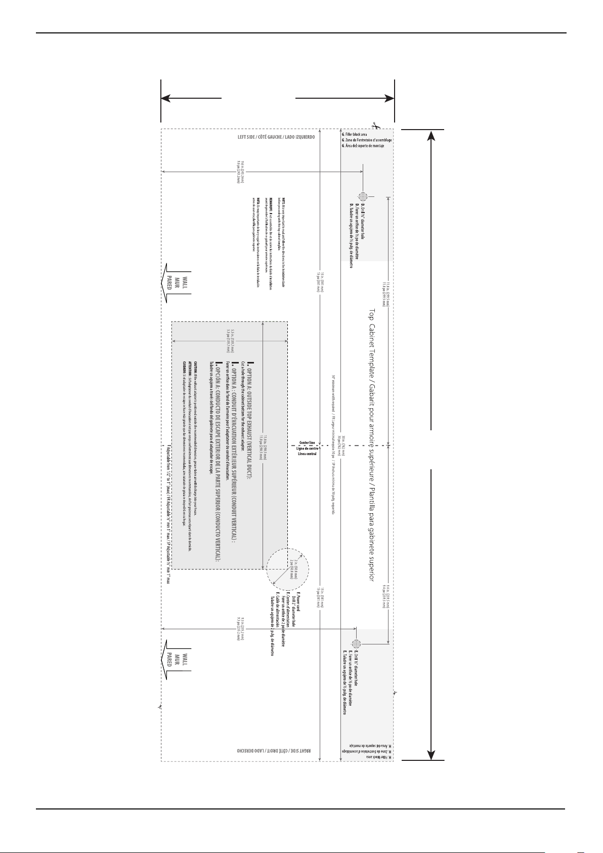
Top cabinet template dimensions
If your top cabinet template is unusable, drill using the dimensions below:
11 in.
(27.9 cm)
30 in.
(76.2 cm)
www.insigniaproducts.com
44
Obtaining replacement parts
Call Insignia Customer Service at 1-877-467-4289.
Specifications
Legal notices
Copyright
INSIGNIA is a trademark of Best Buy and its affiliated companies.
Registered in some countries. Distributed by Best Buy Purchasing, LLC
7601 Penn Ave South, Richfield, MN 55423 U.S.A.
©2019 Best Buy. All rights reserved.
Made in China
Model NS-OTR16SS9 / NS-OTR16WH9
Rated voltage 120V / 60 Hz
Rated input power 1550W
Rated output power 1000W
Microwave capacity 1.6 cu. ft.
Turntable diameter 12.4 in. (31.5 cm)
External dimensions (HxWxD) 16.9 x 29.9 x 17.6 in. (42.9 x 75.9 x 44.6 cm)
Internal dimensions (HxWxD) 10.2 x 21.1 x 14.6 in. (25.9 x 54.1 x 37.1 cm)
Certifications UL and CUL approved
Power cord length 39.8 in. (101 cm)
Net weight 52.5 lbs. (23.8 kg)

www.insigniaproducts.com
45
NS-OTR16SS9 / NS-OTR16WH9
ONE-YEAR LIMITED WARRANTY
Definitions:
The Distributor* of Insignia branded products warrants to you, the original purchaser of this new Insignia-branded product (“Product”), that the
Product shall be free of defects in the original manufacturer of the material or workmanship for a period of one (1) year from the date of your purchase
of the Product (“Warranty Period”).
For this warranty to apply, your Product must be purchased in the United States or Canada from a Best Buy branded retail store or online at
www.bestbuy.com or www.bestbuy.ca, and is packaged with this warranty statement.
How long does the coverage last?
The Warranty Period lasts for 1 year (365 days) from the date you purchased the Product. Your purchase date is printed on the receipt you received
with the Product.
What does this warranty cover?
During the Warranty Period, if the original manufacture of the material or workmanship of the Product is determined to be defective by an authorized
Insignia repair center or store personnel, Insignia will (at its sole option): (1) repair the Product with new or rebuilt parts; or (2) replace the Product at
no charge with new or rebuilt comparable products or parts. Products and parts replaced under this warranty become the property of Insignia and are
not returned to you. If service of Products or parts are required after the Warranty Period expires, you must pay all labor and parts charges. This
warranty lasts as long as you own your Insignia Product during the Warranty Period. Warranty coverage terminates if you sell or otherwise transfer the
Product.
How to obtain warranty service?
If you purchased the Product at a Best Buy retail store location or from a Best Buy online website (www.bestbuy.com or www.bestbuy.ca), please take
your original receipt and the Product to any Best Buy store. Make sure that you place the Product in its original packaging or packaging that provides
the same amount of protection as the original packaging.
To obtain warranty service, in the United States and Canada call 1-877-467-4289. Call agents may diagnose and correct the issue over the phone.
Where is the warranty valid?
This warranty is valid only in the United States and Canada at Best Buy branded retail stores or websites to the original purchaser of the product in the
country where the original purchase was made.
What does the warranty not cover?
This warranty does not cover:
• Customer instruction/education
• Installation
• Set up adjustments
• Cosmetic damage
• Damage due to weather, lightning, and other acts of God, such as power surges
• Accidental damage
• Misuse
• Abuse
• Negligence
• Commercial purposes/use, including but not limited to use in a place of business or in communal areas of a multiple dwelling condominium or
apartment complex, or otherwise used in a place of other than a private home.
• Modification of any part of the Product, including the antenna
• Display panel damaged by static (non-moving) images applied for lengthy periods (burn-in).
• Damage due to incorrect operation or maintenance
• Connection to an incorrect voltage or power supply
• Attempted repair by any person not authorized by Insignia to service the Product
• Products sold “as is” or “with all faults”
• Consumables, including but not limited to batteries (i.e. AA, AAA, C etc.)
• Products where the factory applied serial number has been altered or removed
• Loss or Theft of this product or any part of the product
• Display panels containing up to three (3) pixel failures (dots that are dark or incorrectly illuminated) grouped in an area smaller than one tenth
(1/10) of the display size or up to five (5) pixel failures throughout the display. (Pixel based displays may contain a limited number of pixels that
may not function normally.)
• Failures or Damage caused by any contact including but not limited to liquids, gels or pastes.
REPAIR REPLACEMENT AS PROVIDED UNDER THIS WARRANTY IS YOUR EXCLUSIVE REMEDY FOR BREACH OF WARRANTY. INSIGNIA SHALL NOT BE
LIABLE FOR ANY INCIDENTAL OR CONSEQUENTIAL DAMAGES FOR THE BREACH OF ANY EXPRESS OR IMPLIED WARRANTY ON THIS PRODUCT,
INCLUDING, BUT NOT LIMITED TO, LOST DATA, LOSS OF USE OF YOUR PRODUCT, LOST BUSINESS OR LOST PROFITS. INSIGNIA PRODUCTS MAKES NO
OTHER EXPRESS WARRANTIES WITH RESPECT TO THE PRODUCT, ALL EXPRESS AND IMPLIED WARRANTIES FOR THE PRODUCT, INCLUDING, BUT NOT
LIMITED TO, ANY IMPLIED WARRANTIES OF AND CONDITIONS OF MERCHANTABILITY AND FITNESS FOR A PARTICULAR PURPOSE, ARE LIMITED IN
DURATION TO THE WARRANTY PERIOD SET FORTH ABOVE AND NO WARRANTIES, WHETHER EXPRESS OR IMPLIED, WILL APPLY AFTER THE WARRANTY
PERIOD. SOME STATES, PROVINCES AND JURISDICTIONS DO NOT ALLOW LIMITATIONS ON HOW LONG AN IMPLIED WARRANTY LASTS, SO THE ABOVE
LIMITATION MAY NOT APPLY TO YOU. THIS WARRANTY GIVES YOU SPECIFIC LEGAL RIGHTS, AND YOU MAY ALSO HAVE OTHER RIGHTS, WHICH VARY
FROM STATE TO STATE OR PROVINCE TO PROVINCE.
Contact Insignia:
For customer service please call 1-877-467-4289
www.insigniaproducts.com
INSIGNIA is a trademark of Best Buy and its affiliated companies.
Distributed by Best Buy Purchasing, LLC
7601 Penn Ave South, Richfield, MN 55423 U.S.A.
©2019 Best Buy. All rights reserved.
Made in China

www.insigniaproducts.com
1-877-467-4289 (U.S. and Canada) or 01-800-926-3000 (Mexico)
INSIGNIA is a trademark of Best Buy and its affiliated companies.
Distributed by Best Buy Purchasing, LLC
7601 Penn Ave South, Richfield, MN 55423 U.S.A.
©2019 Best Buy. All rights reserved.
Made in China.
V7 ENGLISH
19-0322