담 당 관리자
MODEL
BRAND
Printing Specification
1. Trim Size (Format) : 185mm x 260 mm
2. Printing Colors
• Cover : 1 COLOR (BLACK)
• Inside : 1 COLOR (BLACK)
3. Stock (Paper)
• Cover : Coated paper , S/White 150 g/㎡
• Inside : Uncoated paper , 백상지 60 g/㎡
4. Printing Method : Off set
5. Bindery : Saddle stitch
6. Language : English (1)
7. Number of pages : 32
Model Description
Part No.
2.
User’s Guide Specification
1.
User’s Guide Specification
Changes
4.
REV.
NO.
MM/DD/YY
SIGNATURE
CHANGE NO.
CHANGE CONTENTS
1
2
3
4
5
7
6
SUFFIX
32/37/42LC7D-UK
42/50PC5D-UL
LG
MFL34797033
(0807-REV04)
KANG
KWANG SUK
07.06.29
8
9
Special Instructions3.
Product Name
USA
Park SY
07.06.29
32/37/42LC7D,
42/50PC5D
“This part contain Eco-hazardous substances (Pb, Cd, Hg, Cr6+, PBB, PBDE, etc.) within LG standard level,
Details should be followed Eco-SCM management standard[LG(56)-A-2524].
Especially, Part should be followed and controlled the following specification.
(1)Eco-hazardous substances test report should be submitted
when Part certification test and First Mass Production.
(2) Especially, Don’t use or contain lead(Pb) and cadmium(Cd) in ink.
N
O
T
E
S
(1) Origin Notification
* LGEMX : Printed in Mexico
* LGERS : Printed in Mexico
* LGEAZ : Printed in Brazil
* LGESP : Printed in Brazil
* LGESY : Printed in China
* LGENT : Printed in China
* LGENP : Printed in China
* LGEIL : Printed in India
* LGEDI : Printed in Indonesia
* LGEIN : Printed in Indonesia
* LGETH : Printed in Thailand
* LGEVN : Printed in Vietnam
* LGEMA : Printed in Poland
* LGEWA : Printed in U.K.
* LGEEG : Printed in Egypt
* LGERA : Printed in Russia
* LGEAK : Printed in Kazakhstan
Sep./14/07 Park sun young S7-95015
Applied PQ test results.
Nov./01/07 Park sun young S7-97591
Changed antenna contents and Simplink function.
Jan./09/07 Park sun young S8-05245
Changed inch form.
Jul./01/08 Yang Hyo-Mi S8-24394
Added the model name and corrected the safety instruchions

Pagination sheet
Pagination sheet
P/NO.MFL34797033
Total pages : 32 pages
2….
Front cover
…. ….
LG(EN)
30
Blank
page
P/NO.
Rear cover
LG
Please read this manual carefully before operating
your set.
Retain it for future reference.
Record model number and serial number of the set.
See the label attached on the back cover and quote
this information to your dealer
when you require service.
LCD TV PLASMA TV
OWNER’S MANUAL
LCD TV MODELS
32LC7D
32LC7DC
37LC7D
42LC7D
32LG10
PLASMA TV MODELS
42PC5D
42PC5DC
50PC5D
50PC5DC
P/NO : MFL34797033 (0807-REV04)
Printed in Korea
www.lgusa.com / www.lgcommercial.com
As an ENERGY STAR
Partner LGE U. S. A.,Inc.
has determined that this
product meets the
ENERGY STAR guidelines
for energy efficiency.
ENERGY STAR is a set of power-saving
guidelines issued by the U.S.
Environmental Protection Agency(EPA).
An extended owner’s manual that contains information
on the advanced features of these LG TV sets is located
on the CD-ROM provided in an electronic version.
To read these files, you will need to use personal computer
(PC) equipped with a CD-ROM drive.
MFL34797033-en-simple 1/20/04 12:34 AM Page 1
2
WARNING / CAUTION
WARNING / CAUTION
To prevent fire or shock hazards, do not expose
this product to rain or moisture.
FCC NOTICE
Class B digital device
This equipment has been tested and found to com-
ply with the limits for a Class B digital device, pur-
suant to Part 15 of the FCC Rules. These limits are
designed to provide reasonable protection against
harmful interference in a residential installation. This
equipment generates, uses and can radiate radio fre-
quency energy and, if not installed and used in
accordance with the instructions, may cause harmful
interference to radio communications. However,
there is no guarantee that interference will not
occur in a particular installation. If this equipment
does cause harmful interference to radio or televi-
sion reception, which can be determined by turning
the equipment off and on, the user is encouraged to
try to correct the interference by one or more of
the following measures:
- Reorient or relocate the receiving antenna.
- Increase the separation between the equipment
and receiver.
- Connect the equipment to an outlet on a circuit
different from that to which the receiver is con-
nected.
- Consult the dealer or an experienced radio/TV
technician for help.
Any changes or modifications not expressly
approved by the party responsible for compliance
could void the user’s authority to operate the
equipment.
CAUTION
Do not attempt to modify this product in any way
without written authorization from LG Electronics.
Unauthorized modification could void the user’s
authority to operate this product
The lightning flash with arrowhead
symbol, within an equilateral triangle,
is intended to alert the user to the
presence of uninsulated “dangerous voltage”
within the product’s enclosure that may be of
sufficient magnitude to constitute a risk of electric
shock to persons.
The exclamation point within an equilateral
triangle is intended to alert the user to
the presence of important operating and main-
tenance (servicing) instructions in the literature
accompanying the appliance.
TO REDUCE THE RISK OF ELECTRIC SHOCK
DO NOT REMOVE COVER (OR BACK). NO
USER SERVICEABLE PARTS INSIDE. REFER TO
QUALIFIED SERVICE PERSONNEL.
WARNING/CAUTION
TO REDUCE THE RISK OF FIRE AND ELECTRIC
SHOCK, DO NOT EXPOSE THIS PRODUCT TO
RAIN OR MOISTURE.
NOTE TO CABLE/TV INSTALLER
This reminder is provided to call the CATV system
installer’s attention to Article 820-40 of the National
Electric Code (U.S.A.). The code provides guidelines for
proper grounding and, in particular, specifies that the
cable ground shall be connected to the grounding sys-
tem of the building, as close to the point of the cable
entry as practical.
MFL34797033-en-simple 1/20/04 12:34 AM Page 2
3
IMPORTANT SAFETY INSTRUCTIONS
SAFETY INSTRUCTIONS
Read these instructions.
Keep these instructions.
Heed all warnings.
Follow all instructions.
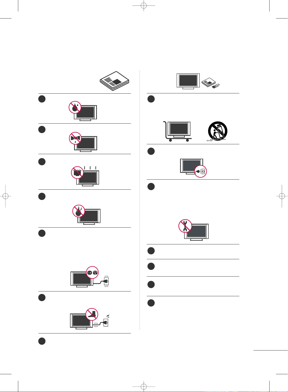
Do not use this apparatus near water.
Clean only with dry cloth.
Do not block any ventilation openings. Install in
accordance with the manufacturer’s instructions.
Do not install near any heat sources such as
radiators, heat registers, stoves, or other apparatus
(including amplifiers)that produce heat.
Do not defeat the safety purpose of the polarized
or grounding-type plug. A polarized plug has
two blades with one wider than the other. A
grounding type plug has two blades and a
third grounding prong, The wide blade or the
third prong are provided for your safety. If the
provided plug does not fit into your outlet,
consult an electrician for replacement of the
obsolete outlet.
Protect the power cord from being walked on
or pinched particularly at plugs, convenience
receptacles, and the point where they exit from
the apparatus.
Only use attachments/accessories specified by
the manufacturer.
Use only with the cart, stand, tripod, bracket,
or table specified by the manufacturer, or sold
with the apparatus. When a cart is used, use
caution when moving the cart/apparatus com-
bination to avoid injury from tip-over.
Unplug this apparatus during lighting storms
or when unused for long periods of time.
Refer all servicing to qualified service personnel.
Servicing is required when the apparatus has
been damaged in any way, such as power-
supply cord or plug is damaged, liquid has
been spilled or objects have fallen into the
apparatus, the apparatus has been exposed to
rain or moisture, does not operate normally, or
has been dropped.
Never touch this apparatus or antenna during
a thunder or lighting storm.
When mounting a TV on the wall, make sure
not to install the TV by the hanging power and
signal cables on the back of the TV.
Do not allow an impact shock or any objects to
fall into the product, and do not drop onto the
screen with something.
CAUTION concerning the Power Cord:
It is recommend that appliances be placed
upon a dedicated circuit; that is, a single
outlet circuit which powers only that appliance
and has no additional outlets or branch
circuits. Check the specification page of this
owner's manual to be certain.
Do not connect too many appliances to the
same AC power outlet as this could result in
fire or electric shock.
1
8
9
10
11
12
13
14
2
3
4
5
6
7
MFL34797033-en-simple 1/20/04 12:34 AM Page 3
4
SAFETY INSTRUCTIONS
Do not overload wall outlets. Overloaded wall
outlets, loose or damaged wall outlets, extension
cords, frayed power cords, or damaged or
cracked wire insulation are dangerous. Any of
these conditions could result in electric shock
or fire. Periodically examine the cord of your
appliance, and if its appearance indicates damage
or deterioration, unplug it, discontinue use of
the appliance, and have the cord replaced with
an exact replacement part by an authorized
servicer. Protect the power cord from physical
or mechanical abuse, such as being twisted,
kinked, pinched, closed in a door, or walked
upon. Pay particular attention to plugs, wall
outlets, and the point where the cord exits the
appliance.
Do not make the TV with the power cord
plugged in. Do not use a damaged or loose
power cord. Be sure do grasp the plug when
unplugging the power cord. Do not pull on the
power cord to unplug the TV.
WARNING - To reduce the risk of fire or elec-
trical shock, do not expose this product to rain,
moisture or other liquids. Do not touch the TV
with wet hands. Do not install this product near
flammable objects such as gasoline or candles
or expose the TV to direct air conditioning.
Do not expose to dripping or splashing and do
not place objects filled with liquids, such as
vases, cups, etc. on or over the apparatus (e.g.
on shelves above the unit).
GGRROOUUNNDDIINNGG
Ensure that you connect the earth ground wire
to prevent possible electric shock (i.e. a TV
with a three-prong grounded AC plug must be
connected to a three-prong grounded AC out-
let). If grounding methods are not possible,
have a qualified electrician install a separate
circuit breaker.
Do not try to ground the unit by connecting it
to telephone wires, lightening rods, or gas pipes.
DDIISSCCOONNNNEECCTTIINNGG DDEEVVIICCEE FFRROOMM MMAAIINNSS
Mains plug is the disconnecting device. The
plug must remain readily operable.
Keep the product away from direct sunlight.
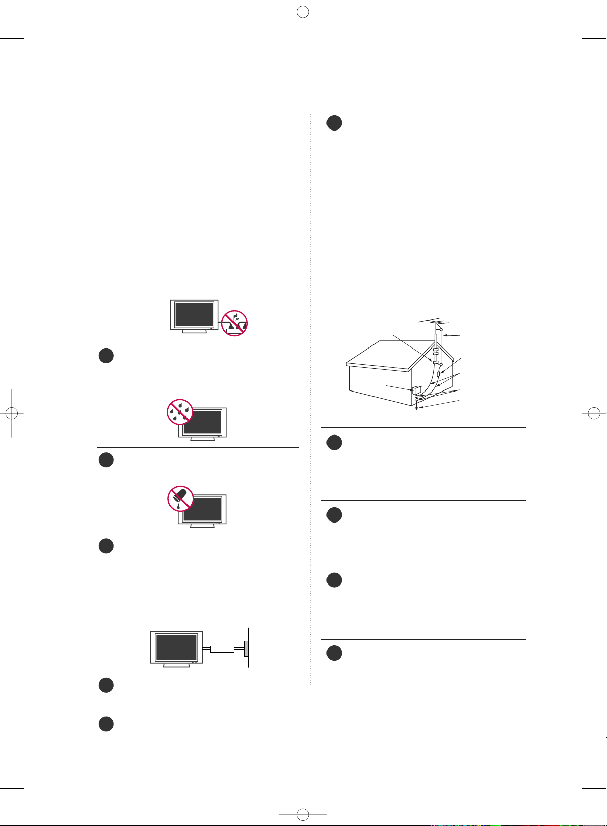
AANNTTEENNNNAASS
OOuuttddoooorr aanntteennnnaa ggrroouunnddiinngg
If an outdoor antenna is installed, follow the
precautions below. An outdoor antenna system
should not be located in the vicinity of over-
head power lines or other electric light or
power circuits, or where it can come in contact
with such power lines or circuits as death or
serious injury can occur.
Be sure the antenna system is grounded so as
to provide some protection against voltage
surges and built-up static charges.
Section 810 of the National Electrical Code
(NEC) in the U.S.A. provides information with
respect to proper grounding of the mast and
supporting structure, grounding of the lead-in
wire to an antenna discharge unit, size of
grounding conductors, location of antenna dis-
charge unit, connection to grounding electrodes
and requirements for the grounding electrode.
AAnntteennnnaa ggrroouunnddiinngg aaccccoorrddiinngg ttoo tthhee
NNaattiioonnaall EElleeccttrriiccaall CCooddee,, AANNSSII//NNFFPPAA 7700
CClleeaanniinngg
When cleaning, unplug the power cord and
scrub gently with a soft cloth to prevent
scratching. Do not spray water or other liquids
directly on the TV as electric shock may occur.
Do not clean with chemicals such as alcohol,
thinners or benzene.
MMoovviinngg
Make sure the product is turned off,
unplugged and all cables have been removed. It
may take 2 or more people to carry larger TVs.
Do not press against or put stress on the front
panel of the TV.
VVeennttiillaattiioonn
Install your TV where there is proper ventila-
tion. Do not install in a confined space such as
a bookcase. Do not cover the product with
cloth or other materials (e.g.) plastic while
plugged in. Do not install in excessively dusty
places.
If you smell smoke or other odors coming from
the TV or hear strange sounds, unplug the
power cord contact an authorized service center.
On Disposal (Only Hg lamp used LCD TV)
The fluorescent lamp used in this product contains a
small amount of mercury. Do not dispose of this
product with general household waste. Disposal of
this product must be carried out in accordance to the
regulations of your local authority.
Power
Supply
Short-circuit
Breaker
Antenna Lead in Wire
Antenna Discharge Unit
(NEC Section 810-20)
Grounding Conductors
(NEC Section 810-21)
Ground Clamps
Power Service Grounding
Electrode System (NEC
Art 250, Part H)
Ground Clamp
Electric Service
Equipment
NEC: National Electrical Code
15
20
21
22
23
24
16
17
18
19
MFL34797033-en-simple 1/20/04 12:34 AM Page 4
5
CONTENTS
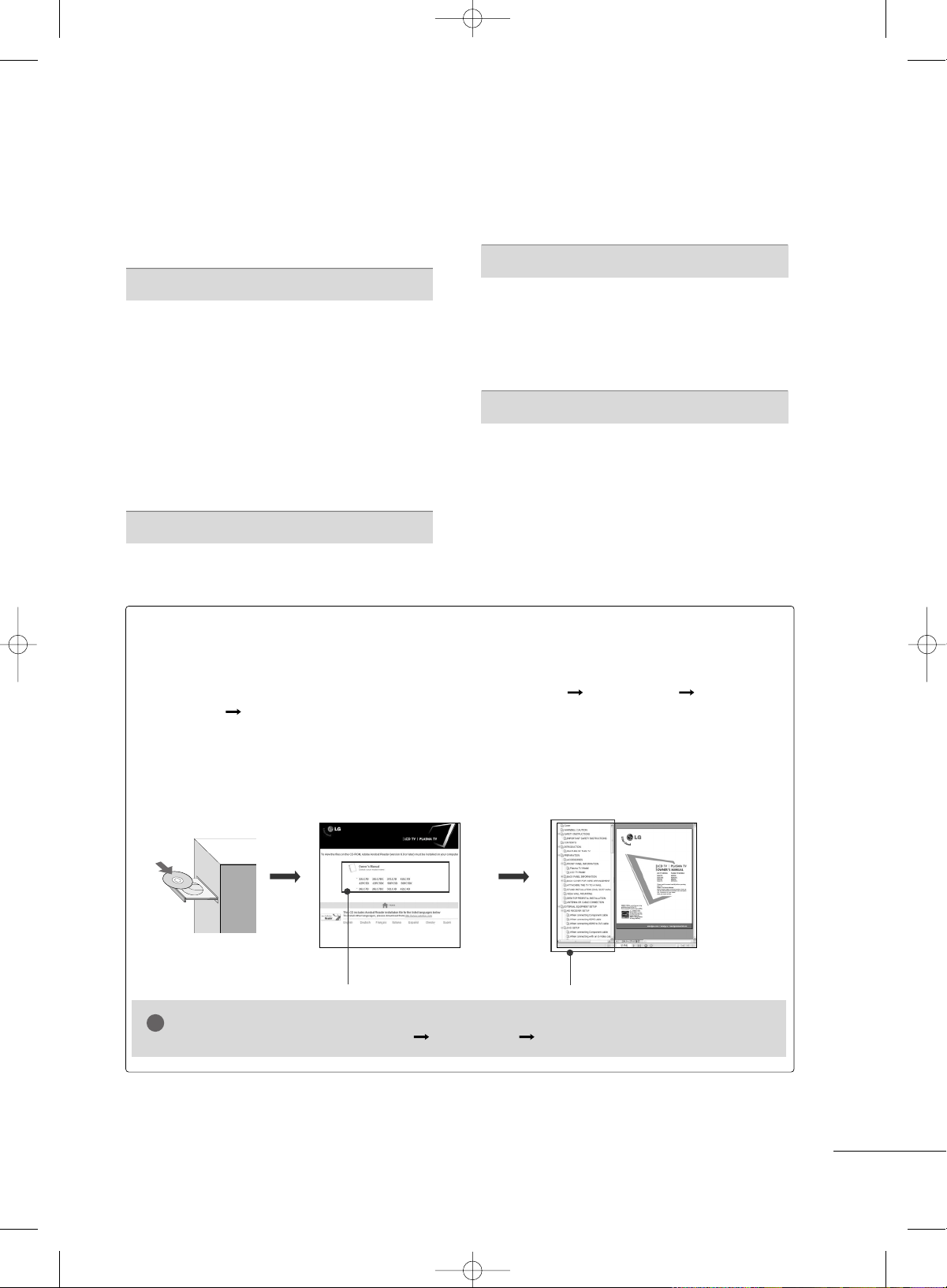
HOW TO USE THE OWNER'S MANUAL ON THE CD-ROM
To view the Owner's Manual on the CD-ROM, Adobe Acrobat Reader must be installed on your PC.
The “ACRORD" folder on the CD-ROM contains the installation programs for them.
If you want to install those programs, Open the “My Computer” Open the “LG” Open the
“ACRORD” double-click your language.
TO VIEW THE OWNER'S MANUAL ON THE CD-ROM
The Owner's Manual files are included in the supplied CD-ROM.
Load the supplied CD-ROM into the CD-ROM drive of your PC.
After a while, the web page of the CD-ROM will open automatically. (for Window only)
GG
If the web page does not appear automatically, open the Owner's Manual file directly.
Open the “My computer” Open the “LG” Open the “index.htm” file.
NOTE
!
When you select your product,
display the PDF file.
You can find the desired contents
easily using the bookmark.
WARNING / CAUTION
. . . . . . . . . . . . . . . . . . . . . . . . . . . . 2
SAFETY INSTRUCTIONS
. . . . . . . . . . . . . . . . . . . . . . . . . . 3
PREPARATION
Accessories . . . . . . . . . . . . . . . . . . . . . . . . . . . . . . . . . . . . . . . . . . . . . . . . . . . . . .
6
Front Panel Information
. . . . . . . . . . . . . . . . . . . . . . . . . . . . . . . . . . . . . .7
Back Panel Information
. . . . . . . . . . . . . . . . . . . . . . . . . . . . . . . . . . . . . . 8
Remote Control Functions
. . . . . . . . . . . . . . . . . . . . . . . . . . . . . . . 10
Back Cover for Wire Arrangement
. . . . . . . . . . . . . . . . . . . . . 12
Attaching the TV to a wall
. . . . . . . . . . . . . . . . . . . . . . . . . . . . . . . . 14
Desktop Pedestal Installation
. . . . . . . . . . . . . . . . . . . . . . . . . . . . 14
Stand Installation
. . . . . . . . . . . . . . . . . . . . . . . . . . . . . . . . . . . . . . . . . . . . 15
VESA Wall Mounting
. . . . . . . . . . . . . . . . . . . . . . . . . . . . . . . . . . . . . . . . 15
Antenna or Cable Connection
. . . . . . . . . . . . . . . . . . . . . . . . . . 16
EXTERNAL EQUIPMENT SETUP
HD Receiver Setup
. . . . . . . . . . . . . . . . . . . . . . . . . . . . . . . . . . . . . . . . . 17
DVD Setup
. . . . . . . . . . . . . . . . . . . . . . . . . . . . . . . . . . . . . . . . . . . . . . . . . . . . . . 18
VCR Setup
. . . . . . . . . . . . . . . . . . . . . . . . . . . . . . . . . . . . . . . . . . . . . . . . . . . . . 19
PC Setup
. . . . . . . . . . . . . . . . . . . . . . . . . . . . . . . . . . . . . . . . . . . . . . . . . . . . . . . . 20
WATCHING TV
Turning On TV
. . . . . . . . . . . . . . . . . . . . . . . . . . . . . . . . . . . . . . . . . . . . . . . . 21
Channel Selection
. . . . . . . . . . . . . . . . . . . . . . . . . . . . . . . . . . . . . . . . . . .
21
Volume Adjustment
. . . . . . . . . . . . . . . . . . . . . . . . . . . . . . . . . . . . . . . . . 21
Channel Search
. . . . . . . . . . . . . . . . . . . . . . . . . . . . . . . . . . . . . . . . . . . . . . . 22
On-Screen Menus Selection
. . . . . . . . . . . . . . . . . . . . . . . . . . . . . 23
APPENDIX
Troubleshooting . . . . . . . . . . . . . . . . . . . . . . . . . . . . . . . . . . . . . . . . . . . . . . 26
Maintenance
. . . . . . . . . . . . . . . . . . . . . . . . . . . . . . . . . . . . . . . . . . . . . . . . . . . 28
Product Specifications
. . . . . . . . . . . . . . . . . . . . . . . . . . . . . . . . . . . . . 29
Open Source Software Notice
. . . . . . . . . . . . . . . . . . . . . . . . . . 30
MFL34797033-en-simple 1/20/04 12:34 AM Page 5
PREPARATION
6
PREPARATION
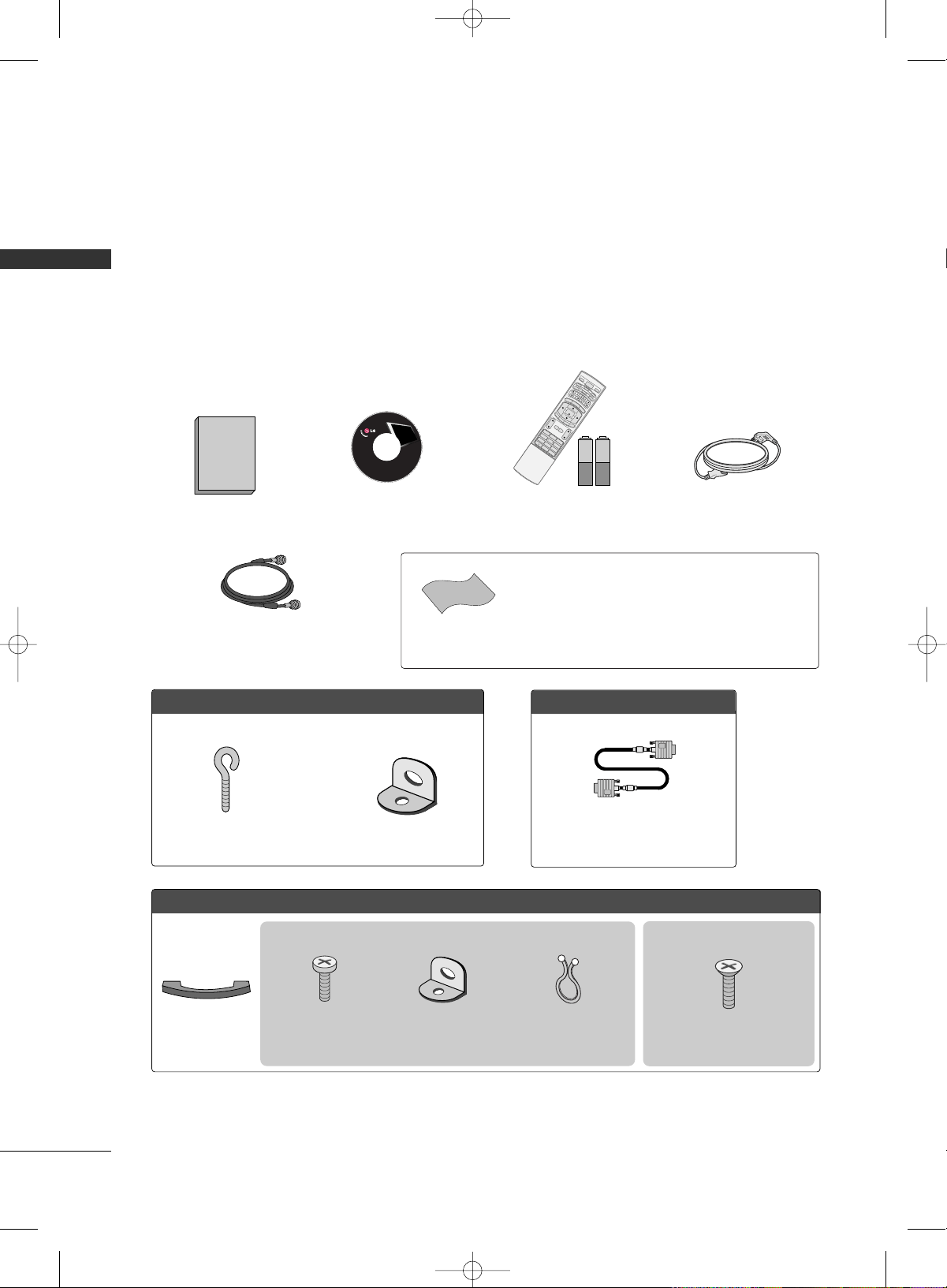
ACCESSORIES
Ensure that the following accessories are included with your product. If an accessory is missing, please con-
tact the dealer where you purchased the product.
User must use shielded signal interface cables (D-sub 15 pin cable) with ferrite cores to maintain standard
compliance for the product.
The accessories can be different from the figures shown here.
For further information, see the the Owner's Manual files supplied CD-ROM.
75ohm Round Cable
OOppttiioonn EExxttrraass
D-sub 15 pin Cable
FFoorr LLCCDD TTVV mmooddeellss
2-Eye-bolts
(Refer to p.14)
2-Wall brackets
(Refer to p.14)
FFoorr PPllaassmmaa TTVV mmooddeellss
Cable
Management
4-Bolts for stand assembly
(Refer to p.15)
3322LLCC77DD//77DDCC,, 3377LLCC77DD,,
3322LLGG1100 oonnllyy
* Slightly wipe stained spot on the exterior only with the polishing
cloth for the product exterior if there is stain or fingerprint on
surface of the exterior.
* Do not wipe roughly when removing stain. Please be cautions of
that excessive pressure may cause scratch or discoloration.
Polishing Cloth
1.5V 1.5V
Owner’s Manual CD Manual
(Refer to p.5)
123
456
78
0
9
BACK
VOL C H
MUTE
FAV
B
R
I
G
H
T
-
MENU
B
R
I
G
H
T
+
ENTER
E
X
I
T
T
I
M
E
R
R
A
T
I
O
S
I
M
P
L
I
N
K
POWER
V
C
R
T
V
DVD
A
U
D
I
O
C
A
B
L
E
S
T
B
MODE
T
V
I
N
P
U
T
INPUT
CH
ENU
B
R
I
G
H
T
+
ENTER
R
A
T
I
O
S
I
M
P
L
I
N
K
1
4
7
Remote Control,
Batteries
Power Cord
Copyright© 2007 LGE,
All Rights Reserved.
This feature is not available for all models
This feature is not available for all models
2- TV Bracket Bolts
(Refer to p.14)
2- TV Brackets,
2- Wall Brackets
(Refer to p.14)
Twist Holder
Arrange the wires with
the twist holder.
(This feature is not available for
all models)
MFL34797033-en-simple 1/20/04 12:34 AM Page 6
PREPARATION
7
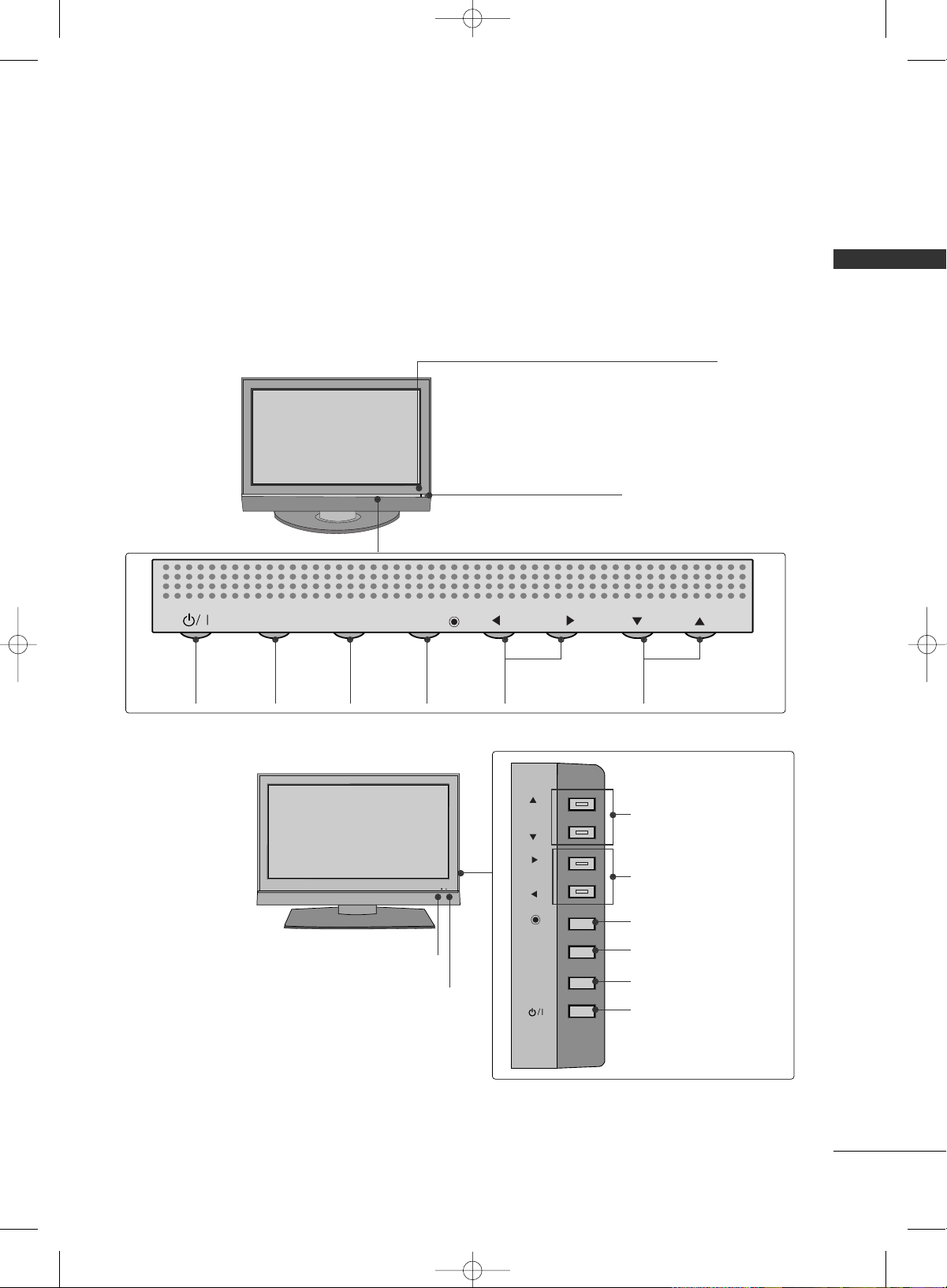
FRONT PANEL INFORMATION
■
Here shown may be somewhat different from your TV.
■
NOTE: If your product has a protection tape attached, remove the tape.
And then wipe the product with a cloth (If a polishing cloth is included with your product, use it).
Front Panel Controls
CH
VOL
MENU
INPUT
ENTER
CH
VOL
MENU
INPUT
ENTER
Power/Standby Indicator
Illuminates red in standby mode.
Illuminates green when the set is switched on.
Remote Control Sensor
POWER
Button
INPUT
Button
MENU
Button
ENTER
Button
VOLUME
(
FF
,
GG
)Buttons
CHANNEL
(
EE
,
DD
)Buttons
CH
VOL
ENTER
MENU
INPUT
CH
CH
VOL
VOL
ENTER
ENTER
MENU
MENU
INPUT
INPUT
Remote Control Sensor
Power/Standby Indicator
Illuminates red in standby mode.
Illuminates green when the set is switched on.
CHANNEL(
DD
,
EE
)Buttons
VOLUME(
FF
,
GG
)Buttons
ENTER Button
MENU Button
INPUT Button
POWER Button
Plasma TV Model
LCD TV Model
MFL34797033-en-simple 1/20/04 12:34 AM Page 7
PREPARATION
8
PREPARATIONPREPARATION
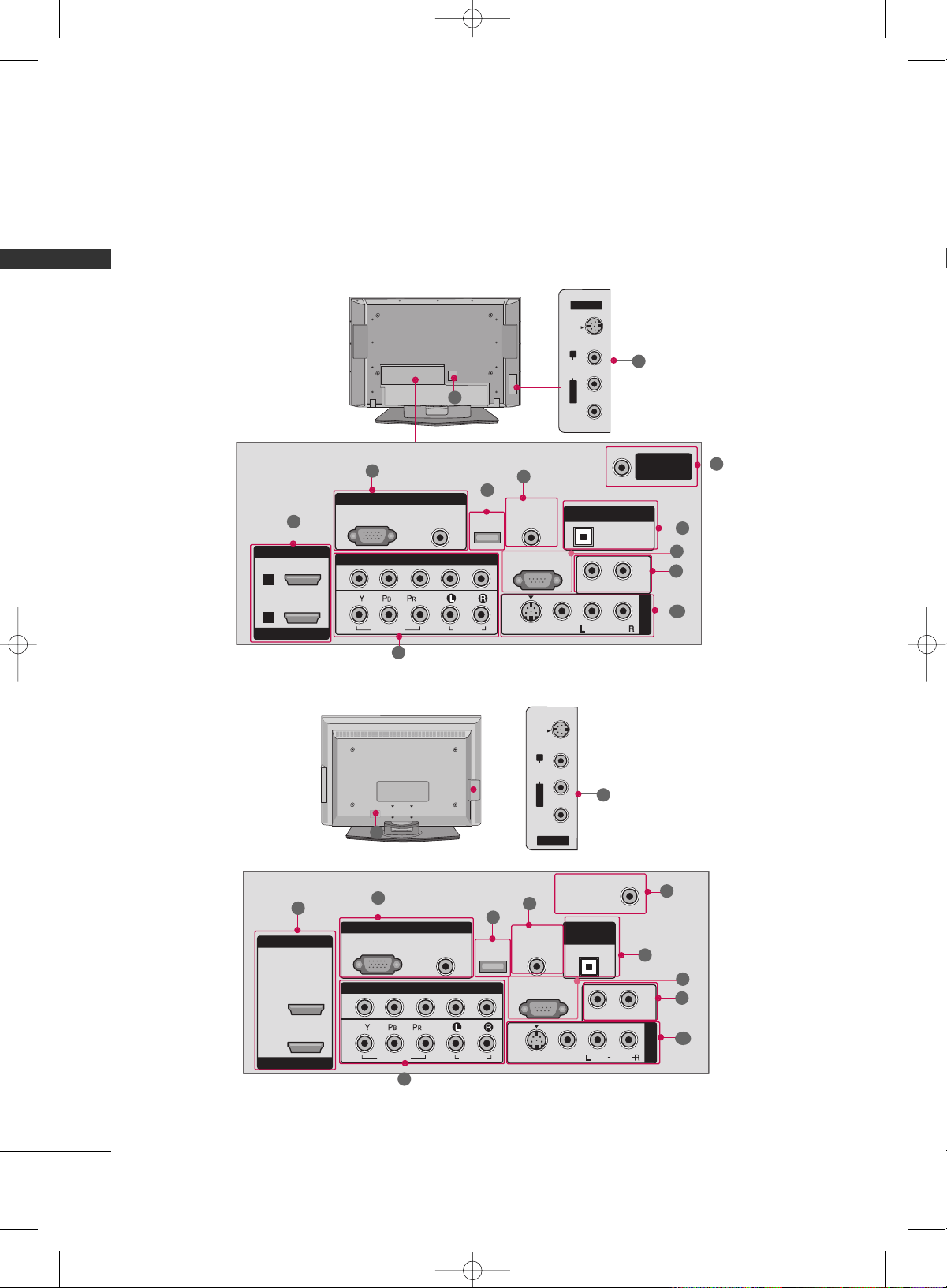
BACK PANEL INFORMATION
■
Here shown may be somewhat different from your TV.
Plasma TV Model
LCD TV Model
R
RGB IN
COMPONENT IN
AUDIO
(RGB/DVI)
RGB(PC)
REMOTE
CONTROL IN
1
2
RS-232C IN
(CONTROL & SERVICE)
VIDEO
AUDIO
VIDEO
AUDIO OUT
MONO
( )
AUDIO
S-VIDEO
AV IN 1
SERVICE
ANTENNA/
CABLE IN
OPTICAL
DIGITAL AUDIO OUT
HDMI IN
HDMI/DVI IN
1
2
AV IN 2
L/MONO
R
AUDIO
VIDEO
S-VIDEO
( )
10
11
AV IN 2
L/MONO
R
AUDIO
VIDEO
S-VIDEO
( )
1
3
5
4
8
6
7
9
2
10
R
RGB IN
HDMI IN
HDMI/DVI IN
COMPONENT IN
AUDIO
(RGB/DVI)
RGB(PC)
REMOTE
CONTROL IN
ANTENNA/
CABLE IN
1
1
2
2
RS-232C IN
(CONTROL & SERVICE)
VIDEO
AUDIO
VIDEO
AUDIO OUT
OPTICAL
MONO
( )
AUDIO
S-VIDEO
DIGITAL
AUDIO OUT
AV IN 1
SERVICE
1
3
5
4
6
7
9
2
10
8
10
11
MFL34797033-en-simple 1/20/04 12:34 AM Page 8
PREPARATION
9
HDMI/DVI IN 1, HDMI IN 2
Connect a HDMI (DVI) connection to either input.
COMPONENT IN
Connect a component video/audio device to these
jacks.
RGB (PC)
Connect the output from a PC.
AUDIO (RGB/DVI)
Connect the audio from a PC or DTV.
SERVICE
Remote Control Port
Connect a wired remote control.
ANTENNA/CABLE IN
Connect over-the air signals to this jack.
Connect cable signals to this jack.
DIGITAL AUDIO OUT
Connect digital audio from various types of equipment.
Note: In standby mode, these ports do not work.
RS-232C IN (CONTROL & SERVICE) PORT
For external control devices.
AUDIO OUT
Connect analog audio to various types of equipment.
AV (Audio/Video) IN
Connect audio/video output from an external
device to these jacks.
S-VIDEO
Connect S-Video out from an S-VIDEO device.
Power Cord Socket
For operation with AC power.
Caution: Never attempt to operate the TV on DC
power.
1
11
2
3
4
5
6
8
7
9
10
MFL34797033-en-simple 1/20/04 12:34 AM Page 9
PREPARATION
10
PREPARATIONPREPARATION
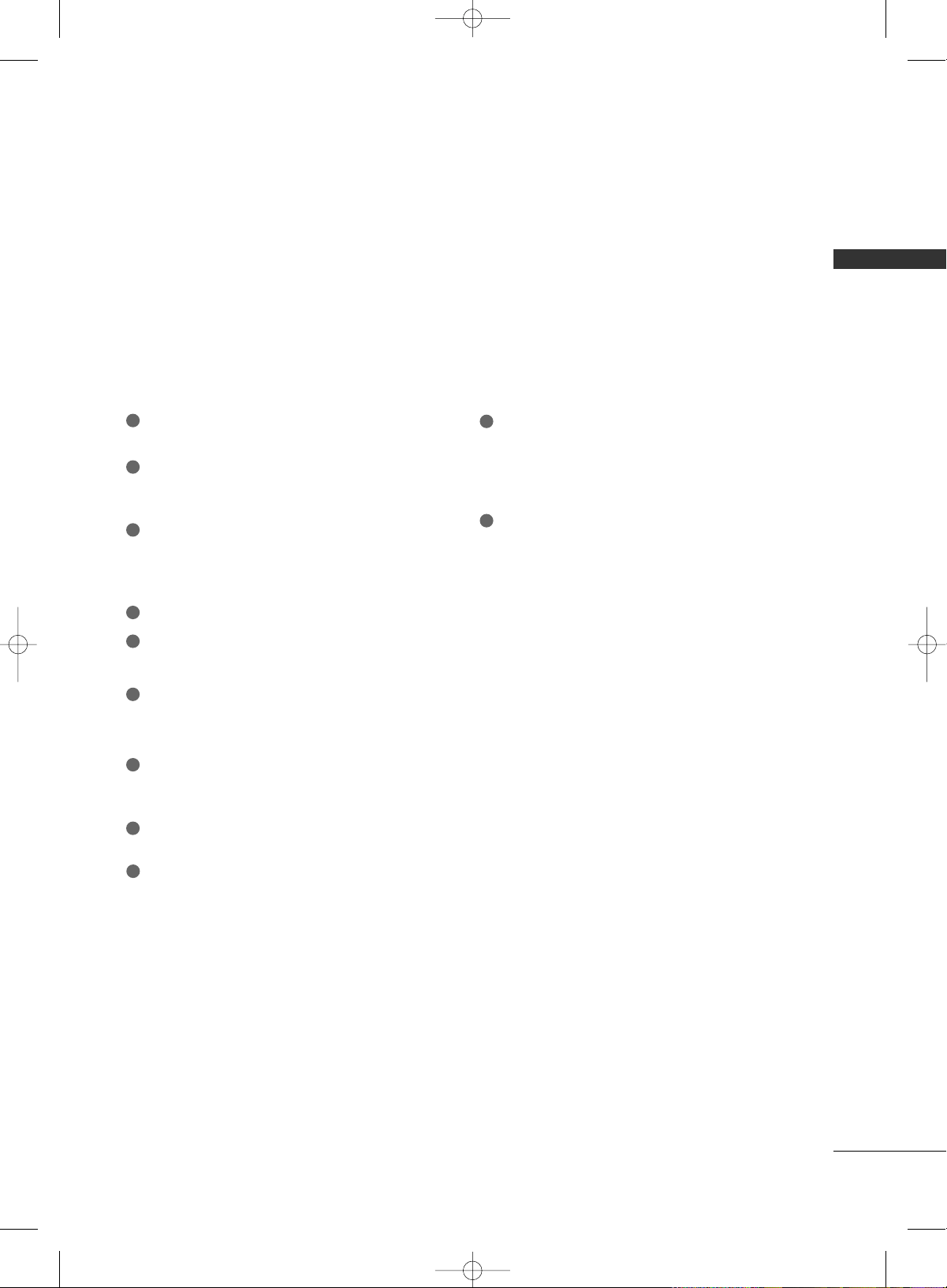
REMOTE CONTROL FUNCTIONS
1 2 3
4 5 6
78
0
9
BACK
VOL CH
MUTE
FAV
BRIGHT -
MENU
BRIGHT +
ENTER
EXIT
TIMER
RATIO
SIMPLINK
POWER
VCR
TV
DVD
AUDIO
CABLE
STB
MODE
TV INPUT
INPUT
When using the remote control, aim it at the remote control sensor on the TV.
MODE
MENU
BRIGHT -/ +
THUMBSTICK
(Up/Down/Left
Right/ENTER)
EXIT
TIMER
RATIO
SIMPLINK
VOLUME UP
/DOWN
MUTE
FAV
CHANNEL
UP/DOWN
— (DASH)
BACK
Select the remote’s operating mode. TV, DVD, VCR,
AUDIO, CABLE, or STB.
Control video cassette recorders or DVD players.
Displays the main menu.
Adjust the brightness on screen.
Navigate the on-screen menus and adjust the system set-
tings to your preference.
Clear all on-screen displays and return to TV viewing
from any menu.
Select the amount of time before your TV turns off auto-
matically.
Change the aspect ratio.
See a list of AV devices connected to TV. When you tog-
gle this button, the SimpLink menu appears at the screen.
Increase/decrease the sound level.
Switch the sound on or off.
Scroll through the programmed Favorite channels.
Select available channels.
Used to enter a program number for multiple program
channels such as 2-1, 2-2, etc.
Tune to the last channel viewed.
VCR/DVD
control buttons
NUMBER button
MFL34797033-en-simple 1/20/04 12:34 AM Page 10
PREPARATION
11
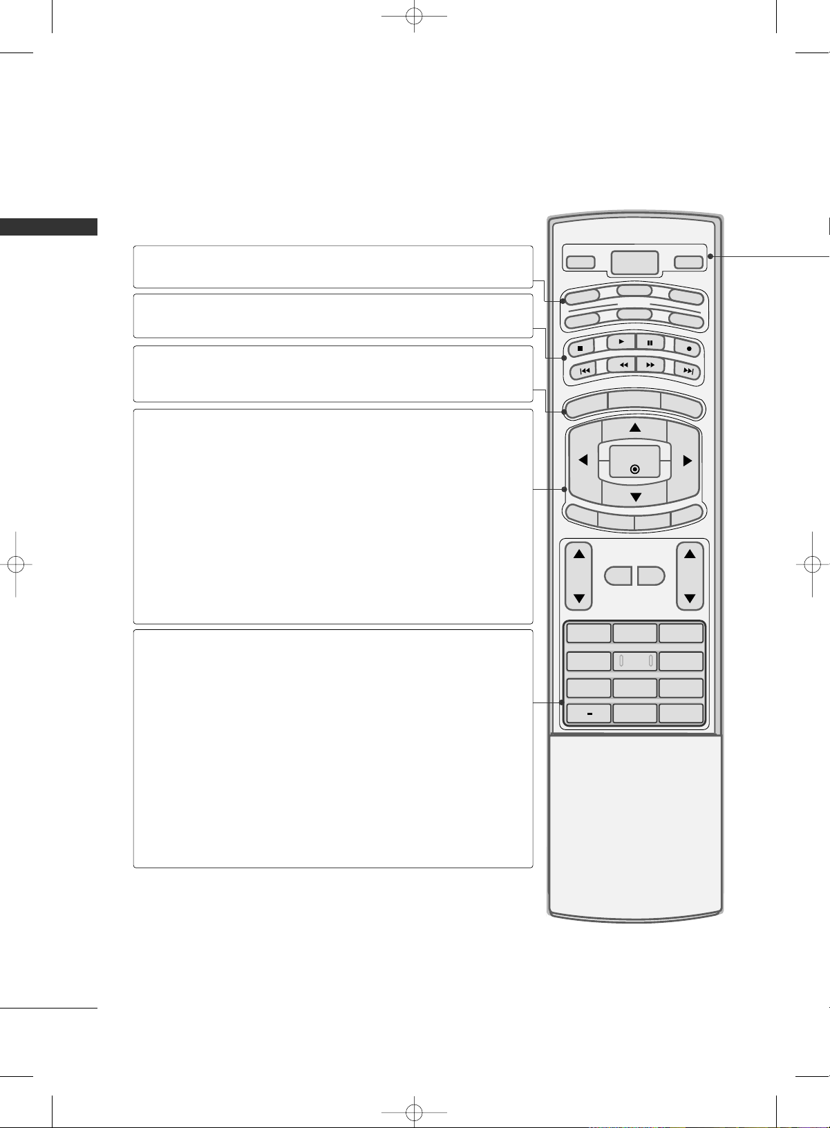
ADJUST
SAP
SOUND
PICTURE
CC
1 2 3
4 5 6
78
0
9
BACK
PICTURE
SOUND
SAP
CC
ADJUST
Selects the factory preset picture depend on
the viewing environment.
Selects the factory preset sound for type of
program.
Analog mode: Selects MTS sound (Mono,
Stereo, or a SAP)
DTV mode: Changes the audio language.
Select a closed caption.
Adjust the screen resolution, position, size and
phase.
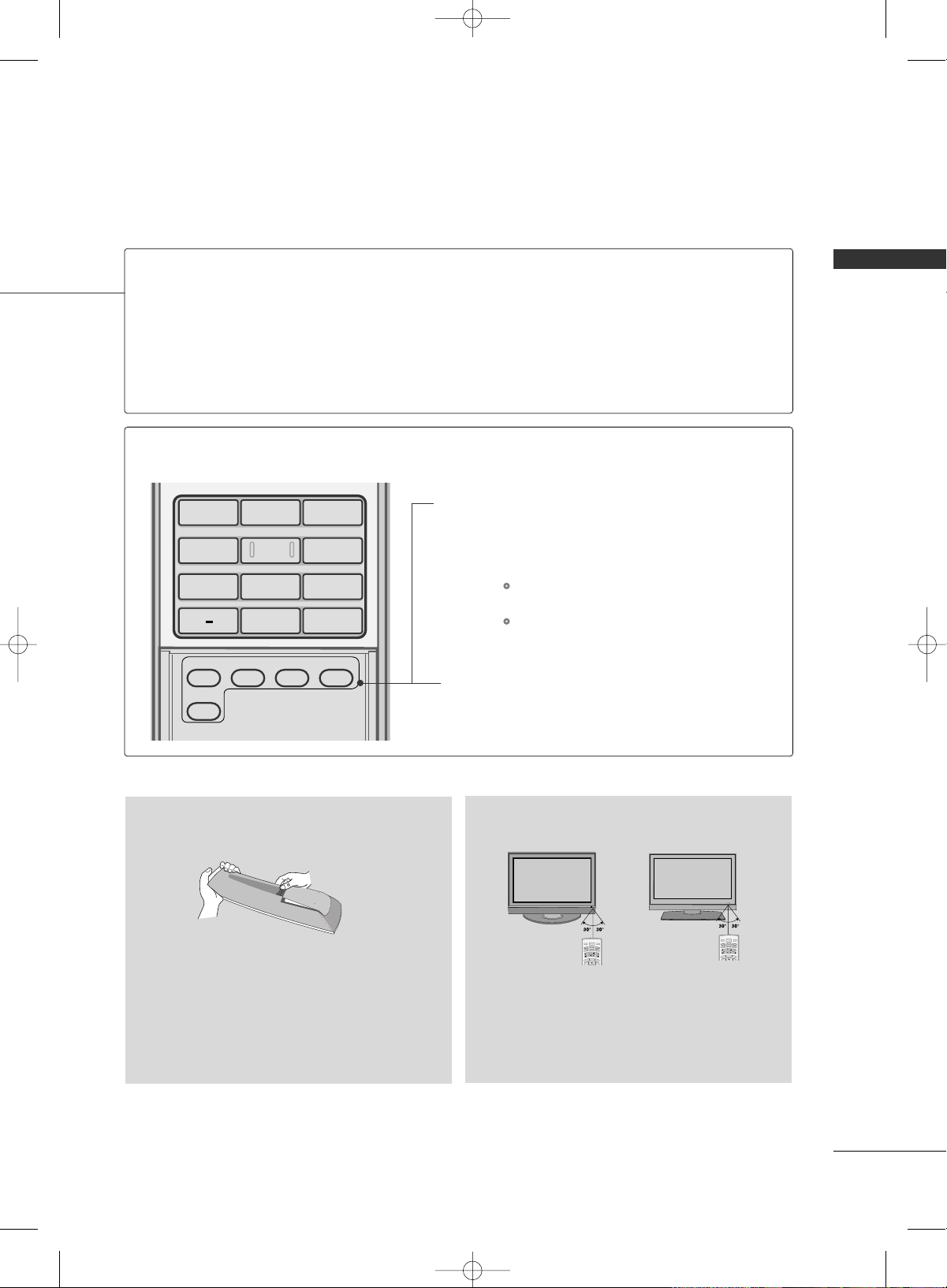
Inside the Sliding Cover
■
Open the battery compartment cover on the back
side and install the batteries matching correct
polarity
(
+ with +, - with -
)
.
■
Install two 1.5V AA batteries. Don’t mix old or
used batteries with new ones.
■
Close cover.
■
Use a remote control up to 7 meters distance
and 30 degree (left/right) within the receiving
unit scope.
■
Dispose of used batteries in a recycle bin to
preserve environment.
B
R
I
G
H
T
-
MENU
B
R
IG
H
T
+
POWER
V
C
R
T
V
DVD
A
U
D
I
O
CABLE
S
T
B
MODE
TV INPUT
INPUT
B
R
I
G
H
T
-
MENU
B
R
IG
H
T
+
POWER
V
C
R
T
V
DVD
A
U
D
I
O
CABLE
S
T
B
MODE
TV INPUT
INPUT
Installing Batteries
Remote control effective range
POWER
TV INPUT
INPUT
Turns your TV or any other programmed equipment on or off, depending on the mode.
In AV 1-2, Component 1-2, RGB-PC, HDMI1, and HDMI2 input sources, screen returns to the
last TV channel.
External input modes rotate in regular sequence: TV, AV1-2, Component 1-2, RGB-PC, HDMI1 and
HDMI2.
(AV 1-2, Component 1-2, RGB-PC, HDMI1, and HDMI2 input sources are linked automatically,
only if a device is connected.)
MFL34797033-en-simple 1/20/04 12:34 AM Page 11
PREPARATION
12
PREPARATIONPREPARATION
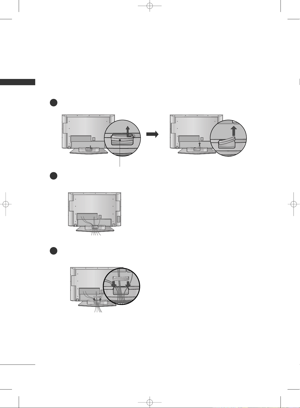
BACK COVER FOR WIRE ARRANGEMENT
Plasma TV Model
Hold the CABLE MANAGEMENT with both hands and pull it backward as shown.
Connect the cables as necessary.
To connect an additional equipment, see the EXTERNAL EQUIPMENT SETUP section.
1
2
Install the CABLE MANAGEMENT as shown.
3
CABLE MANAGEMENT
■
Here shown may be somewhat different from your TV.
MFL34797033-en-simple 1/20/04 12:34 AM Page 12
PREPARATION
13
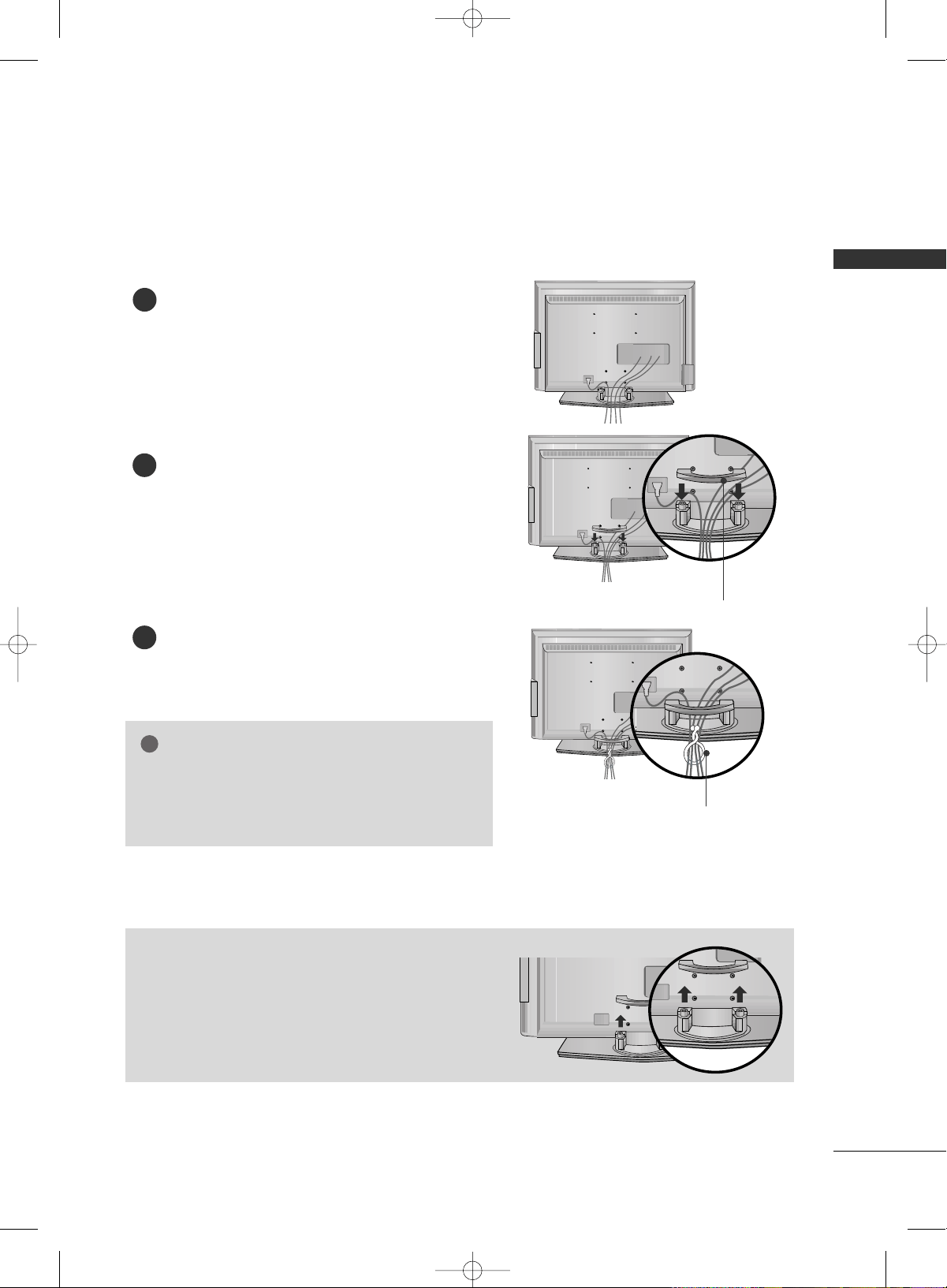
LCD TV Model
Connect the cables as necessary.
To connect an additional equipment, see the
EXTERNAL EQUIPMENT SETUP section.
Install the CABLE MANAGEMENT as shown.
How to remove the CABLE MANAGEMENT
GG
Hold the CABLE MANAGEMENT with both hands and
pull it backward.
CABLE MANAGEMENT
TWISTER HOLDER
GG
Do not hold the CABLE MANAGEMENT when moving
the product.
- If the product is dropped, you may be injured or the
product may be broken.
NOTE
!
1
2
Bundle the cables using the supplied TWISTER HOLDER.
(This feature is not available for all models.)
3
MFL34797033-en-simple 1/20/04 12:34 AM Page 13
PREPARATION
14
PREPARATIONPREPARATION
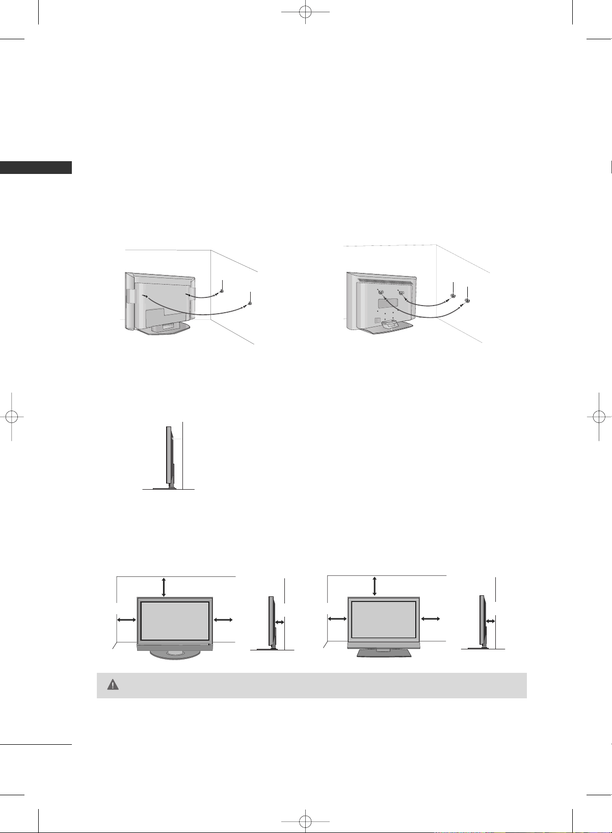
ATTACHING THE TV TO A WALL
We recommend that you set up the TV close to a wall so it cannot fall over if pushed backwards.
Additionally, we recommend that the TV be attached to a wall so it cannot be pulled in a forward direction,
potentially causing injury or damaging the product.
Caution: Please make sure that children don’t climb on or hang from the TV.
Plasma TV Model LCD TV Model
■
Insert the eye-bolts (or TV brackets and bolts) to tighten the product to the wall as shown in the picture.
*If your product has the bolts in the eye-bolts position before inserting the eye-bolts, loosen the bolts.
Secure the wall brackets with the bolts (not provided as parts of the product, must purchase separately) to
the wall. Match the height of the bracket that is mounted on the wall to the holes in the product.
Ensure the eye-bolts or brackets are tightened securely.
■
Use a sturdy rope (not provided as parts of the product, must pur-
chase separately) to tie the product. It is safer to tie the rope so it
becomes horizontal between the wall and the product.
For proper ventilation, allow a clearance of 4inches on all four sides from the wall.
4 inches
4 inches
4 inches
4 inches
4 inches
4 inches
4 inches
4 inches
GG
Ensure adequate ventilation by following the clearance recommendations.
CAUTION
Plasma TV Model LCD TV Model
DESKTOP PEDESTAL INSTALLATION
■
This feature is not available for all models.
■
Here shown may be somewhat different from your TV.
MFL34797033-en-simple 1/20/04 12:34 AM Page 14
PREPARATION
15
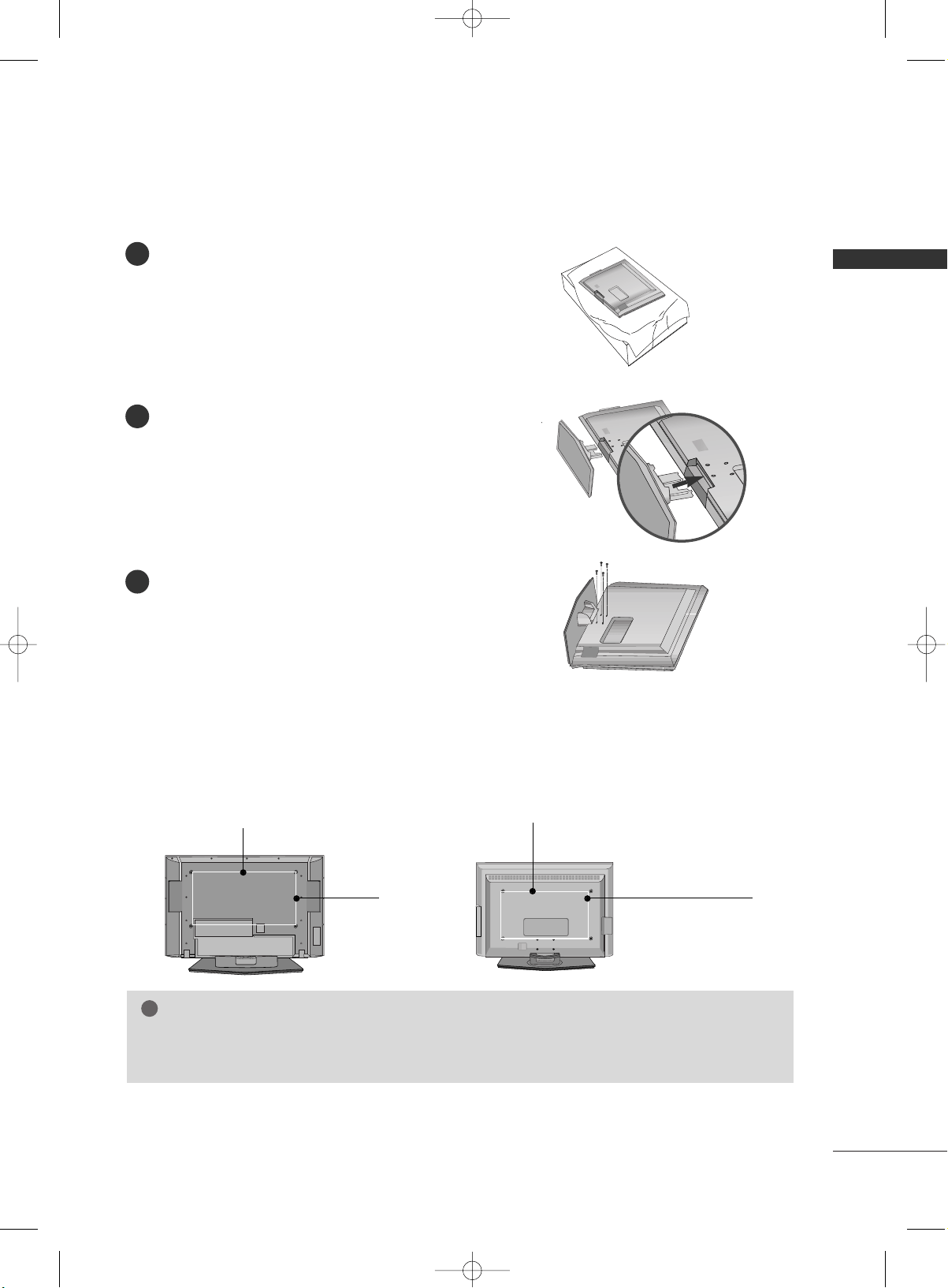
STAND INSTALLATION (Only 32LC7D/7DC, 37LC7D, 32LG10)
Carefully place the product screen side down on
a cushioned surface that will protect product and
screen from damage.
Assemble the product stand with the product as
shown.
Securely install the 4 bolts provided.
1
2
3
VESA WALL MOUNTING
This product accepts a VESA-compliant mounting interface pad. (optional)
There 4 threaded holes are available for attaching the bracket.
GG
Screw length needed depends on the wall mount used. For further information, refer to the VESA
Wall Mounting Instruction Guide.
NOTE
!
R
( )
R
( )
Plasma TV Model LCD TV Model
600 mm
400 mm
400 mm
(32LC7D/7DC,32LG10 only:
100 mm)
600 mm
(32LC7D/7DC,32LG10 only: 200 mm)
MFL34797033-en-simple 1/1/04 6:57 AM Page 15
PREPARATION
16
PREPARATIONPREPARATION
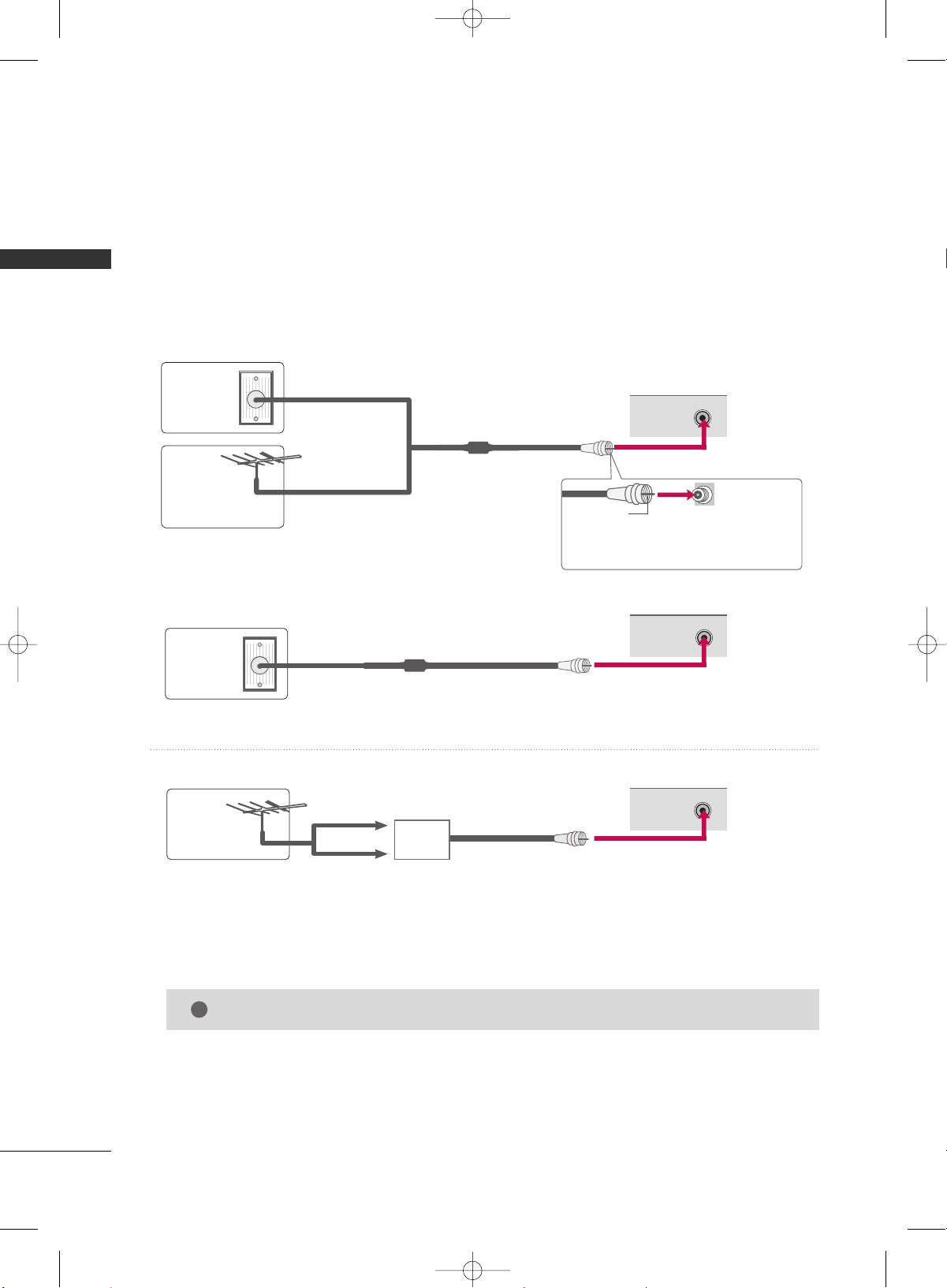
ANTENNA OR CABLE CONNECTION
1. Antenna (Analog or Digital)
Wall Antenna Socket or Outdoor Antenna without a Cable Box
Connections.
For optimum picture quality, adjust antenna direction if needed.
2. Cable
Wall
Antenna
Socket
Outdoor
Antenna
(VHF, UHF)
Cable TV
Wall Jack
Multi-family Dwellings/Apartments
(Connect to wall antenna socket)
RF Coaxial Wire (75 ohm)
RF Coaxial Wire (75 ohm)
Single-family Dwellings /Houses
(Connect to wall jack for outdoor antenna)
Be careful not to bend the bronze wire
when connecting the antenna.
Copper Wire
GG
The TV will let you know when the analog, cable, and digital channel scans are complete.
NOTE
!
■
To improve the picture quality in a poor signal area, please purchase a signal amplifier and install properly.
■
If the antenna needs to be split for two TV’s, install a 2-Way Signal Splitter.
■
If the antenna is not installed properly, contact your dealer for assistance.
Antenna
UHF
Signal
Amplifier
VHF
R
ANTENNA/
CABLE IN
( )
R
ANTENNA/
CABLE IN
( )
R
ANTENNA/
CABLE IN
( )
MFL34797033-en-simple 1/20/04 12:34 AM Page 16

EXTERNAL EQUIPMENT SETUP
17
EXTERNAL EQUIPMENT SETUP
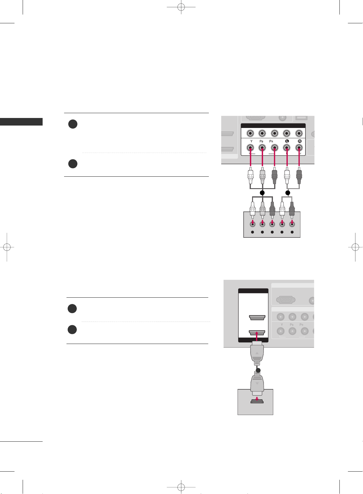
HD RECEIVER SETUP
This TV can receive Digital Over-the-air/Cable signals without an external digital set-top box. However, if you do
receive digital signals from a digital set-top box or other digital external device, refer to the figure as shown below.
MI IN
/DVI IN
AUDIO
(RGB/DVI)
RGB(PC)
R
CON
R
(CONT
( )
S-
( )
COMPONENT IN
1
2
VIDEO
AUDIO
Y L RPB PR
( )
SERVICE
When connecting Component cable
1 2
1. How to connect
Connect the video outputs
(
Y, PB, PR
)
of the digital set
top box to the
CCOOMMPPOONNEENNTT IINN VVIIDDEEOO 11
jacks on
the set. Match the jack colors (Y = green, PB = blue, and
P
R
= red).
Connect the audio output of the digital set-top box to
the
CCOOMMPPOONNEENNTT IINN AAUUDDIIOO 11
jacks on the set.
2
1
2. How to use
■
Turn on the digital set-top box.
(
Refer to the owner’s manual for the digital set-top box. operation
)
■
Select
CCoommppoonneenntt 11
input source by using the
IINNPPUUTT
button on the remote control.
■
If connected to
CCOOMMPPOONNEENNTT IINN22
input, select
CCoommppoonneenntt 22
input source.
■
To prevent the equipment damage, never plug in any power cords until you have finished connecting all equipment.
■
This part of EXTERNAL EQUIPMENT SETUP mainly use picture for LCD TV model.
Signal
480i
480p
720p
1080 i
1080 p
Component 1/2
Yes
Yes
Yes
Yes
Yes
HDMI1/DVI,
HDMI2
No
Yes
Yes
Yes
Yes
Y, CB/PB, CR/PR
Horizontal Vertical
Frequency
(
KHz
)
Frequency
(
Hz
)
15.73 59.94
15.73 60.00
31.47 59.94
31.50 60.00
44.96 59.94
45.00 60.00
33.72 59.94
33.75 60.00
26.97 23.976
27.00 24.00
33.71 29.97
33.75 30.00
67.432 59.94
67.50 60.00
Resolution
720x480i
720x480p
1280x720p
1920x1080i
1920x1080p
MFL34797033-en-simple 1/20/04 12:34 AM Page 17
EXTERNAL EQUIPMENT SETUP
18
EXTERNAL EQUIPMENT SETUP
When connecting Component cable
R
(CONT
( )
S-
COMPONENT IN
1
2
VIDEO
AUDIO
Y L RPB PR
( )
(
)
I/DVI IN
Connect the video outputs
(
Y, PB
, PR
)
of the DVD to the
CCOOMMPPOONNEENNTT IINN VVIIDDEEOO11
jacks on the set.
Match the jack colors
(
Y = green, P
B = blue, and PR = red
)
.
Connect the audio outputs of the DVD to the
CCOOMMPPOONNEENNTT IINN AAUUDDIIOO11
jacks on the set.
1. How to connect
2. How to use
■
Turn on the DVD player, insert a DVD.
■
Select
CCoommppoonneenntt 11
input source by using the
IINNPPUUTT
button on the remote control.
■
If connected to
CCOOMMPPOONNEENNTT IINN 22
input, select
CCoommppoonneenntt 22
input source.
■
Refer to the DVD player's manual for operating instructions.
2
1
1 2
DVD SETUP
( )
RGB IN
COMPONENT I
AUD
(RGB/
RGB(PC)
1
2
VIDEO
( )
HDMI IN
HDMI/DVI IN
1
2
HDMI-DVD OUTPUT
( )
1
When connecting HDMI cable
Connect the HDMI output of the DVD to the
HHDDMMII//DDVVII IINN 11
or
HHDDMMII IINN 22
jack on the set.
No separated audio connection is necessary.
HDMI supports both audio and video.
1. How to connect
2. How to use
■
Select
HHDDMMII11
or
HHDDMMII22
input source by using the
IINNPPUUTT
button on the remote control.
■
Refer to the DVD player's manual for operating instructions.
2
1
MFL34797033-en-simple 1/20/04 12:34 AM Page 18
EXTERNAL EQUIPMENT SETUP
19
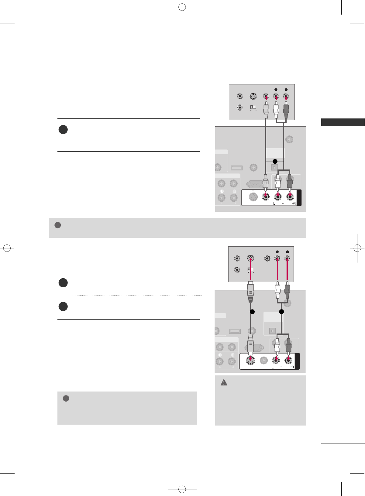
VCR SETUP
GG
Do not connect to both Video
and S-Video at the same time. In
the event that you connect both
Video and the S-Video cables,
only the S-Video will work.
CAUTION
When connecting with a RCA cable
GG
The picture quality is improved: compared to normal
composite (RCA cable) input.
NOTE
!
T IN
UDIO
GB/DVI)
ANTENNA/
CABLE IN
RS-232C IN
(CONTROL & SERVICE)
AUDIO
AUDIO OUT
( )
AV IN 1
VIDEO
MONO
( )
AUDIO
S-VIDEO
( )
REMOTE
CONTROL IN
SERVICE
DIGITAL
AUDIO OUT
OPTICAL
L R
S-VIDEO VIDEO
OUTPUT
SWITCH
ANT IN
ANT OUT
( )
(
)
T IN
UDIO
B/DVI)
ANTENNA/
CABLE IN
RS-232C IN
(CONTROL & SERVICE)
AUDIO
AUDIO OUT
AV IN 1
VIDEO
MONO
( )
AUDIO
S-VIDEO
REMOTE
CONTROL IN
SERVICE
DIGITAL
AUDIO OUT
OPTICAL
L R
S-VIDEO VIDEO
OUTPUT
SWITCH
ANT IN
ANT OUT
Connect the
AAUUDDIIOO
/
VVIIDDEEOO
jacks between TV and
VCR. Match the jack colors (Video = yellow, Audio Left
= white, and Audio Right = red)
1. How to connect
2. How to use
■
Insert a video tape into the VCR and press PLAY on the
VCR.
(
Refer to the VCR owner’s manual.
)
■
Select
AAVV11
input source by using the
IINNPPUUTT
button on
the remote control.
■
If connected to
AAVV IINN22
, select
AAVV22
input source.
When connecting with an S-Video cable
Connect the S-VIDEO output of the VCR to the
SS --VVIIDDEEOO
input on the set.
Connect the audio outputs of the VCR to the
AAUUDDIIOO
input jacks on the set.
1. How to connect
2. How to use
■
Insert a video tape into the VCR and press PLAY on the VCR.
(
Refer to the VCR owner’s manual.
)
■
Select
AAVV11
input source by using the
IINNPPUUTT
button on the
remote control.
■
If connected to
AAVV IINN22
, select
AAVV22
input source.
1
2
1
GG
If you have a mono VCR, connect the audio cable from the VCR to the
AAUUDDIIOO LL//MMOONNOO
jack of the set.
NOTE
!
1
1
2
MFL34797033-en-simple 1/20/04 12:34 AM Page 19
EXTERNAL EQUIPMENT SETUP
20
EXTERNAL EQUIPMENT SETUP
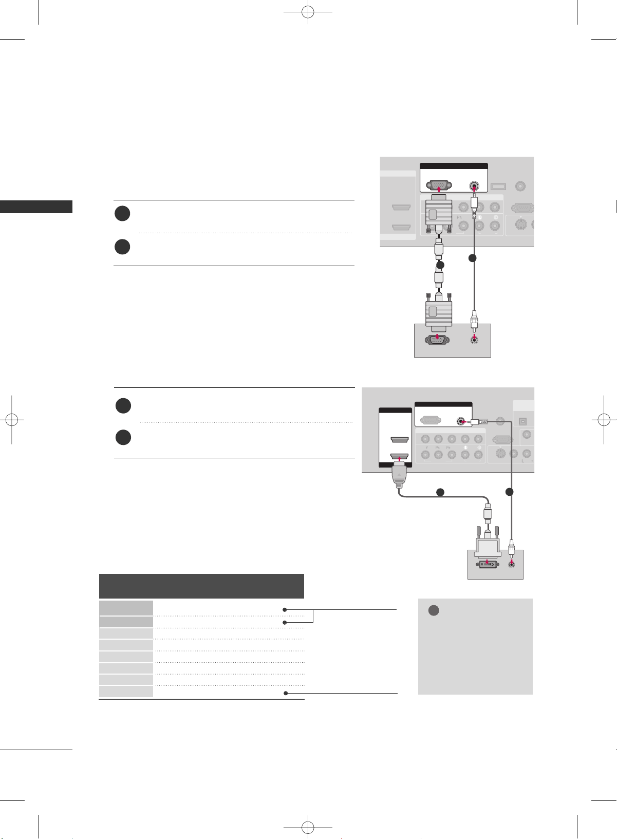
PC SETUP
When connecting HDMI to DVI cable
COMPONENT IN
ANTENNA/
CABLE IN
1
2
RS-232C IN
(CONTROL & SERVICE)
VIDEO
AUDIO
AUDIO
VIDEO
MONO
( )
A
S-VIDEO
HDMI IN
HDMI/DVI IN
1
2
RGB IN
AUDIO
(RGB/DVI)
DVI-PC OUTPUT
RGB(PC)
( )
AUDIO
REMOTE
CONTROL IN
SERVICE
DIGITAL
AUDIO OUT
OPTICAL
1
2
Connect the DVI output of the PC to the
HHDDMMII//DDVVII
IINN 11
jack on the set.
Connect the PC audio output to the
AAUUDDIIOO
((
RRGGBB//DDVVII
))
jack on the set.
1. How to connect
2. How to use
■
Turn on the PC and the TV.
■
Select
HHDDMMII11
input source by using the
IINNPPUUTT
button on
the remote control.
2
1
When connecting D-sub 15pin cable
( )
COMPONENT IN
1
2
RS-232C IN
(CONTROL & SERV
VIDEO
AUDIO
VI
( )
S-VIDEO
RGB IN
AUDIO
(RGB/DVI)
RGB(PC)
RGB OUTPUT AUDIO
REMOTE
CONTROL IN
SERVICE
HDMI IN
HDMI/DVI IN
1
2
Connect the RGB output of the PC to the
RRGGBB
((
PP CC
))
jack on the set.
Connect the PC audio output to the
AAUUDDIIOO
((
RRGGBB//DDVVII
))
jack on the set.
1. How to connect
2. How to use
■
Turn on the PC and the TV.
■
Select
RRGGBB--PPCC
input source by using the
IINNPPUUTT
button
on the remote control.
2
1
1
2
Supported Display Specifications
Horizontal Vertical
Frequency
(
KHz
)
Frequency
(
Hz
)
31.469 70.08
31.469 70.08
31.469 59.94
37.879 60.31
48.363 60.00
47.776 59.87
47.720 59.799
47.130 59.65
Resolution
720x400
1360x768
640x350
640x480
800x600
1024x768
1280x768
1366x768
RGB-PC, HDMI1/DVI-PC mode
* RGB-PC mode only
* LCD TV only
GG
Depending on graphic
card and signal status,
there can be some
shaking to find best
picture in a little time.
NOTE
!
MFL34797033-en-simple 1/20/04 12:34 AM Page 20
WATCHING TV
21
TURNING ON TV
WATCHING TV
NOTE
!
GG
If you intend to be away on vacation, disconnect the power plug from the wall power outlet.
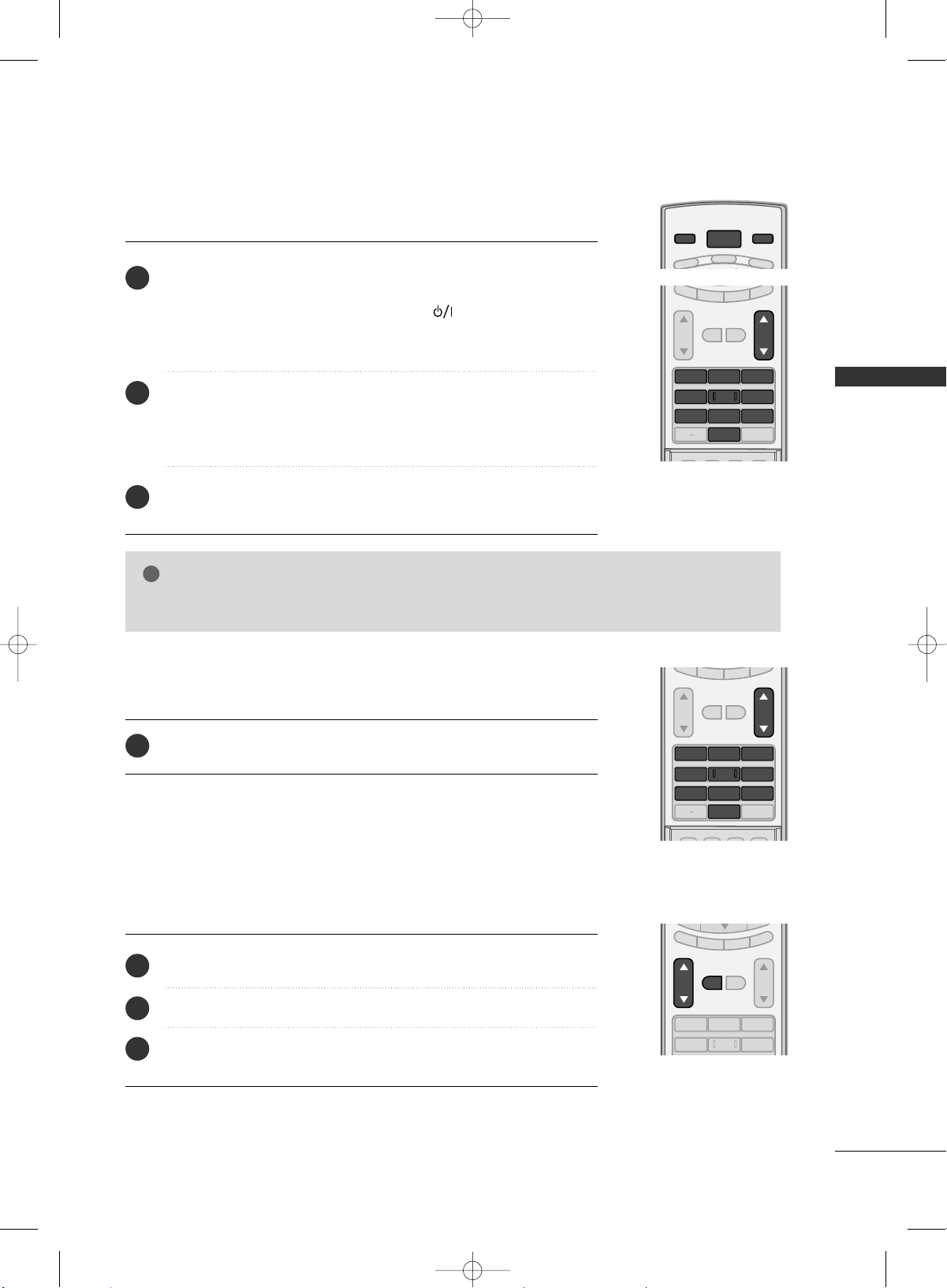
First, connect power cord correctly.
At this moment, the TV switches to standby mode.
■
In standby mode to turn TV on, press the ,
IINNPPUUTT
,
CCHH ((
DD
or
EE
))
button on the TV or press the
PPOOWWEERR
,
IINNPPUUTT
,
TTVV IINNPPUUTT
,
CCHH((
DD
or
EE
))
,
NNuummbbeerr ((00
~
99))
button on the remote control.
Select the viewing source by using the
TTVV IINNPPUUTT
,
IINNPPUUTT
button on the
remote control.
■
This TV is programmed to remember which power state it was last set to,
even if the power cord is out.
When finished using the TV, press the
PPOOWWEERR
button on the remote con-
trol. The TV reverts to standby mode.
POWER
VCR
TV
DVD
MODE
TV INPUT
INPUT
SAP
SOUND
PICTURE
CC
123
456
78
0
9
BACK
VOL CH
MUTE
FAV
EXIT
TIMER
RATIO
SIMPLINK
1
2
3
SAP
SOUND
PICTURE
CC
123
456
78
0
9
BACK
VOL CH
MUTE
FAV
EXIT
TIMER
RATIO
SIMPLINK
Press the
CCHH ((
DD
or
EE
))
or
NNUUMMBBEERR
buttons to select a channel number.
1
VOLUME ADJUSTMENT
CHANNEL SELECTION
Press the
VVOOLL ((
DD
or
EE
))
button to adjust the volume.
If you want to switch the sound off, press the
MMUUTTEE
button.
You can cancel the Mute function by pressing the
MMUUTTEE
or
VVOOLL ((
DD
or
EE
))
button.
123
456
VOL CH
MUTE
FAV
EXIT
TIMER
RATIO
SIMPLINK
Adjust the volume to suit your personal preference.
1
2
3
MFL34797033-en-simple 1/20/04 12:34 AM Page 21
WATCHING TV
22
WATCHING TV
CHANNEL SEARCH
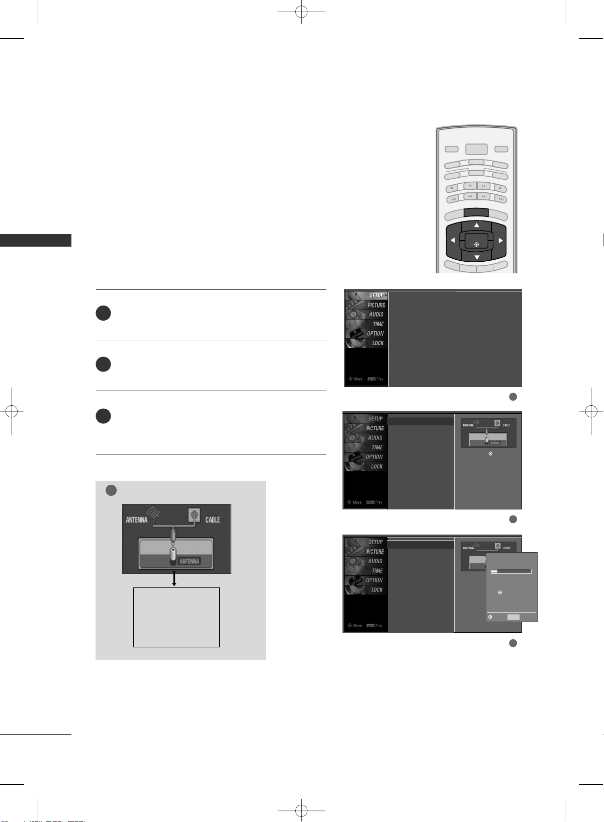
Press the
MMEENNUU
button and then use
DD
or
EE
button
to select the
SSEETTUUPP
menu.
Press the
GG
button and then use
DD
or
EE
button to
select
AAuuttoo TTuunniinngg
.
Press the
EENNTTEERR
button to begin the channel search.
Allow
AAuuttoo TTuunniinngg
to complete the channel search
cycle for
AANNTTEENNNNAA
and
CCAABBLLEE
.
Automatically finds all channels available through antenna
or cable inputs, and stores them in memory on the channel
list.
Run Auto Tuning again after any Antenna/Cable connection
changes.
A password is required to gain access to Auto Tuning menu
if the Lock System is turned on.
2
3
1
1
2
3
B
RIG
HT -
BRIGHT +
ENTER
TIMER
RATIO
SIMPLINK
POWER
VCR
TV
DVD
AUDIO
CABLE
STB
MODE
TV INPUT
INPUT
EXIT
MENU
Auto Scan (Auto Tuning)
Auto Tuning
G
Manual Tuning
Channel Edit
Selection (
G
or ) leads you to
the Auto Tuning screen.
Auto Tuning
Manual Tuning
Channel Edit
Selection (
G
or ) leads
you to the Auto Tuning
screen.
NOTE
!
Analog TV antenna
Digital DTV antenna
Analog CATV cable
Digital CADTV cable
Processing Auto Tuning...
DTV Ch.23
Found Channel(s): 16
Press to stop the current
scan and start ANALOG
ANTENNA channel scan.
MENU Prev
Next
Auto Tuning
Manual Tuning
Channel Edit
MFL34797033-en-simple 1/20/04 12:34 AM Page 22
WATCHING TV
23
ON-SCREEN MENUS SELECTION
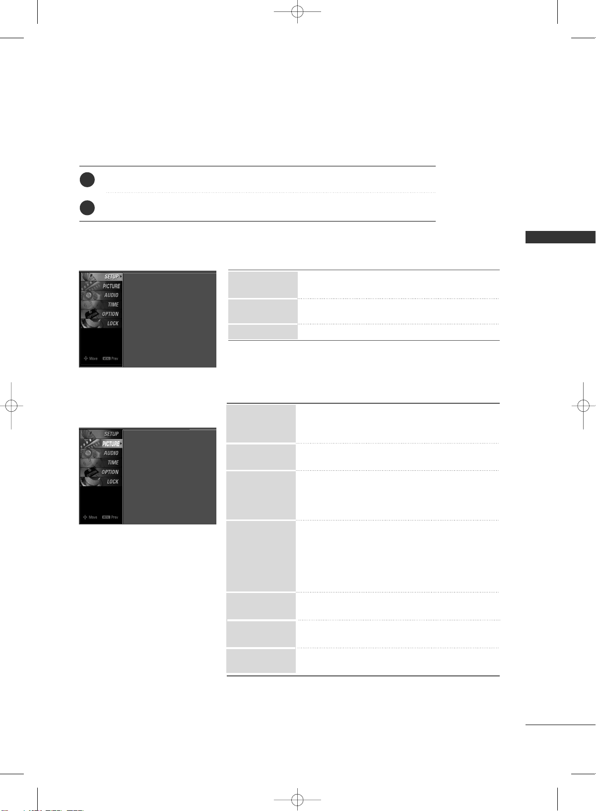
Press the
MMEENNUU
button and then use
DD
or
EE
button to select the each menu.
Press the
GG
button and then use
DD EE FF GG
button to display the available menus.
Your TV's OSD
(
On Screen Display
)
may differ slightly from what is shown in this manual.
2
1
■
All available TV channels are searched and stored
automatically.
■
User can do manual channel selection and add or
delete individual channels.
■
You can add or delete in the channel list.
Channel Edit
Manual Tuning
Auto Tuning
SETUP
Auto Tuning
Manual Tuning
Channel Edit
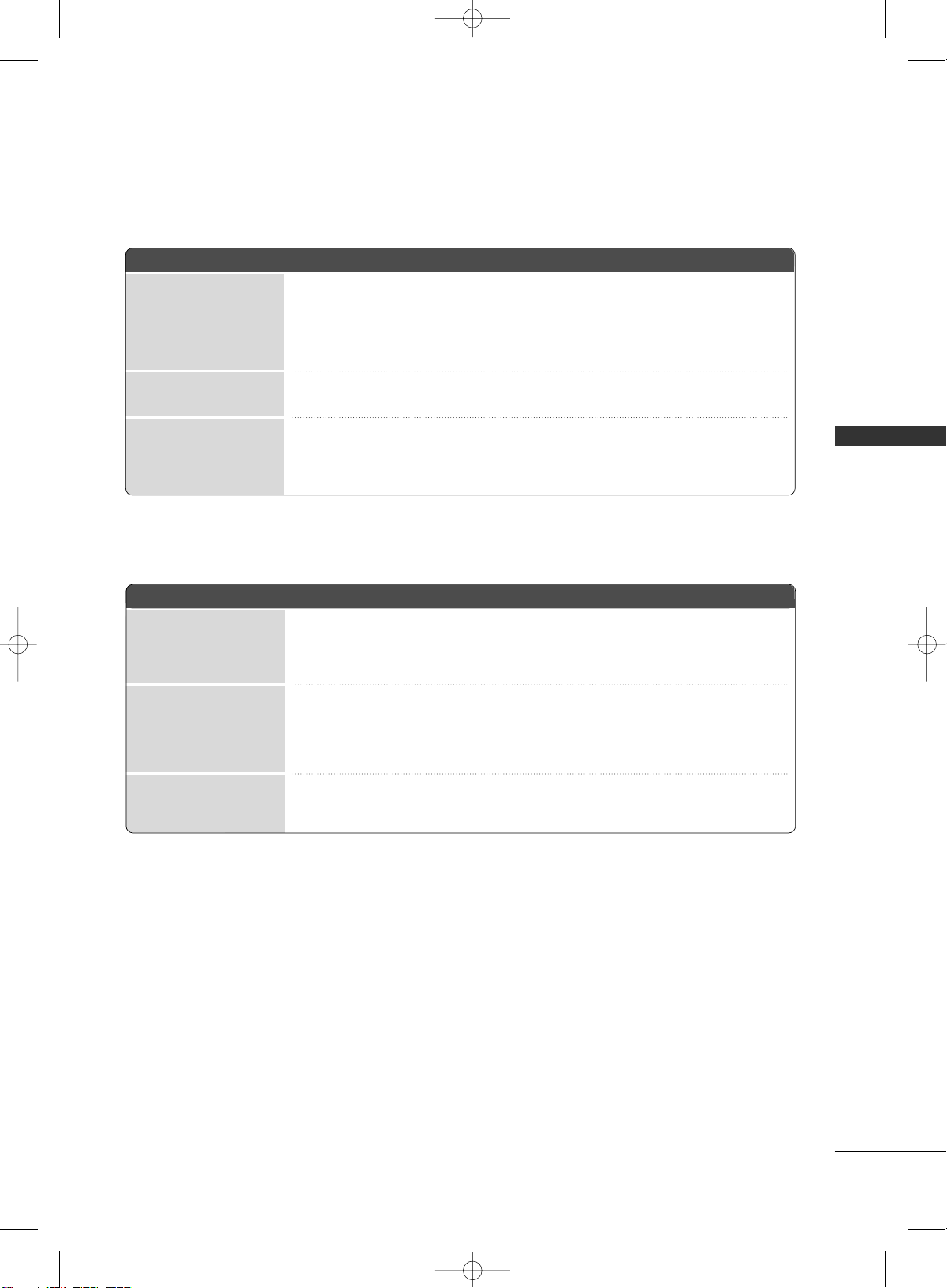
■
Select the preset value in the Picture Mode menu
based on the program category: Dynamic, Standard,
Mild, User1, User2.
■
Choose one of three automatic color adjustments
: Cool, Medium, Warm, User
■
It is LG Electronic’s unique picture improving tech-
nology to display a real HD source through an
advanced digital signal processing algorithm.
■
Select Auto or Manual (XD Contrast, XD Color, XD Noise).
■
Cinema 3:2 Mode (On, Off)
Set up the TV for the best picture appearance for
viewing movies.
■
Black Level (Low, High)
Adjusting the contrast and the brightness of the
screen using the black level of the screen.
■
Select the desired picture format.
: Set by program, 4:3, 16:9, Zoom1, Zoom2, Just Scan.
■
Use to quickly reset all the Picture menu options to
their original factory preset values.
■
Adjust the screen Resolution, Position, Size, Phase,
Reset.
XD
Advanced
Picture Reset
Color Temperature
Picture Mode
PICTURE
Picture Mode : User1
Color Temperature : Cool
XD
Advanced
Aspect Ratio : 16:9
Picture Reset
Screen
Aspect Ratio
Screen
MFL34797033-en-simple 1/20/04 12:34 AM Page 23
WATCHING TV
24
WATCHING TV
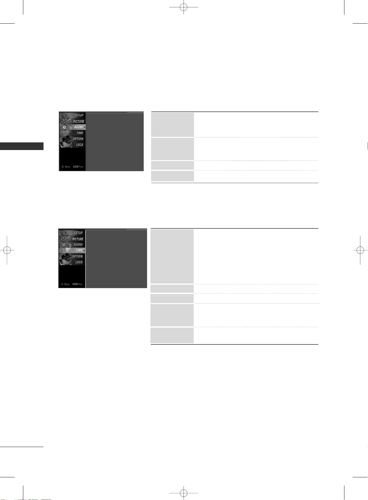
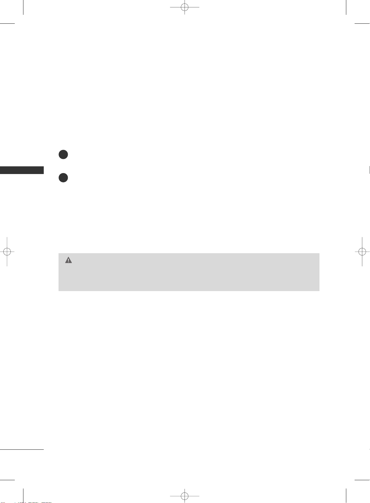
AUDIO
Sound Mode : Standard
Auto Volume : On
Balance : 0
TV Speaker : On
■
Sound Mode lets you enjoy the best sound with-
out any special adjustment.
: Standard, Music, Movie, Sports and User
■
Scans for changes in sound levels during commer-
cials, then adjusts the sound to match the specified
audio level.
■
Adjust the left/right sound of speaker.
■
Turn the TV speaker On or off.
Balance
TV Speaker
Auto Volume
Sound Mode
TIME
Clock : Oct 19, 2006, 03:44 AM
Off Time : Off
On Time : Off
Sleep Time : Off
Auto Sleep : Off
■
Auto: The time is set automatically from a digital
channel signal.
Select your viewing area time zone.
Select Auto, Off, On depending on whether or
not your viewing area observes Daylight Saving
time.
■
Manual: Set the clock manually.
■
Select On or Off.
■
Select On or Off.
■
Select the amount of time before your TV turns off
automatically: Off, 10, 20, 30, 60, 90, 120, 180,
240.
■
TV will be automatically turned off, in case of no sig-
nal for 10 minutes.
Off Time
On Time
Sleep Time
Clock
Auto Sleep
MFL34797033-en-simple 1/20/04 12:34 AM Page 24
WATCHING TV
25
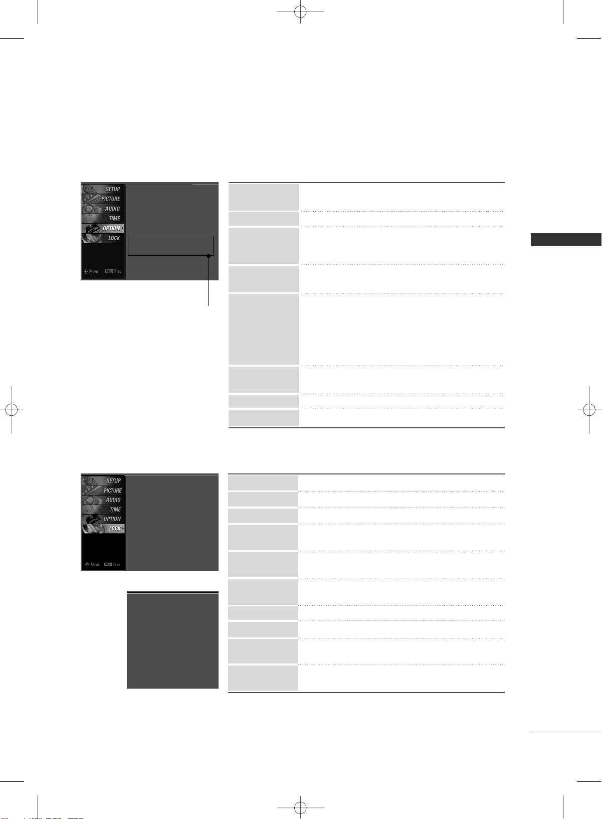
■
Select your desired language for on screen menus
: English, Spanish, French.
■
Set a label to each input source.
■
Control and play other AV devices connected to the
TV through HDMI cable without additional cables
and settings.
■
This feature can be used to prevent unauthorized
viewing by locking out the front panel controls.
■
Mode: When selecting Off, Submenus for Analog,
DTV, and Digital Option become disabled.
■
Analog: CC1~ CC4 , Text1~ Text4.
■
Digital: Service1~ Service6
■
Digital Option: Customize the DTV/CADTV captions
that appear on your screen.
■
Use it to minimize any fixed image on the screen.
: Normal, Orbiter, Inversion, White Wash.
■
Reduces the plasma display power consumption.
■
Choose the desired TV ID number.
SimpLink
key Lock
ISM Method
Low Power
Caption
Input Label
Language
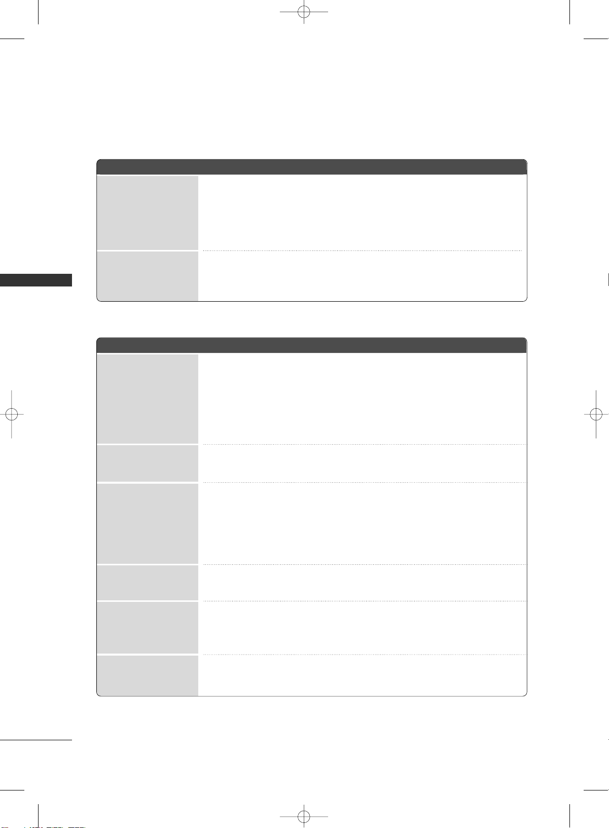
■
Select On or Off.
■
Change the password.
■
Select a channel number that you wish to block.
■
Blocks movies according to the movie ratings limits
specified.
■
Prevents children from watching certain children's
TV programs, according to the ratings limit set.
■
Based on the ratings, blocks certain TV programs
that you and your family do not want to view.
■
Selecting canadian english language rating system.
■
Selecting canadian french language rating system.
■
This function may become available in the future and
will be available only for digital channel signal.
■
Enables you to select a source to block from the
external source devices you have hooked up.
Block Channel
Movie Rating
TV Rating-Children
TV Rating-General
TV Rating-English
TV Rating-French
Downloadable
Rating
Input Block
Set Password
Lock System
For USA
OPTION
LOCK
Language : English
Input Label
SimpLink : Off
Key Lock : Off
Caption : Off
ISM Method : Orbiter
Low Power : Off
Set ID : 1
Set ID
Lock System : Off
Set Password
Block Channel
Movie Rating
TV Rating-Children
TV Rating-General
Downloadable Rating
Input Block
For Canada
Lock System : Off
Set Password
Block Channel
TV Rating-English
TV Rating-French
Downloadable Rating
Input Block
Plasma TV model only
MFL34797033-en-simple 1/20/04 12:34 AM Page 25
APPENDIX
26
APPENDIX
TROUBLESHOOTING
TThhee ooppeerraattiioonn ddooeess nnoott wwoorrkk nnoorrmmaallllyy..
TThhee vviiddeeoo ffuunnccttiioonn ddooeess nnoott wwoorrkk..
No picture &No sound
No or poor color
or poor picture
Poor reception on
some channels
Lines or streaks
in pictures
Horizontal/vertical bars
or picture shaking
Picture appears slowly
after switching on
The remote control
doesn’t work
Power is suddenly
turned off
■
Check to see if there is any object between the product and the remote control
causing obstruction. Ensure you are pointing the remote control directly at the TV.
■
Ensure that the batteries are installed with correct polarity (+ to +, - to -).
■
Ensure that the correct remote operating mode is set: TV, VCR etc.
■
Install new batteries.
■
Is the sleep timer set?
■
Check the power control settings. Power interrupted.
■
No broadcast on station tuned with Auto off activated.
■
Check whether the product is turned on.
■
Try another channel. The problem may be with the broadcast.
■
Is the power cord inserted into wall power outlet?
■
Check your antenna direction and/or location.
■
Test the wall power outlet, plug another product’s power cord into the outlet
where the product’s power cord was plugged in.
■
This is normal, the image is muted during the product startup process. Please
contact your service center, if the picture has not appeared after five minutes.
■
Adjust Color in menu option.
■
Keep a sufficient distance between the product and the VCR.
■
Try another channel. The problem may be with the broadcast.
■
Are the video cables installed properly?
■
Activate any function to restore the brightness of the picture.
■
Check for local interference such as an electrical appliance or power tool.
■
Station or cable product experiencing problems, tune to another station.
■
Station signal is weak, reorient antenna to receive weaker station.
■
Check for sources of possible interference.
■
Check antenna (Change the direction of the antenna).
MFL34797033-en-simple 1/20/04 12:34 AM Page 26
APPENDIX
27
TThheerree iiss aa pprroobblleemm iinn PPCC mmooddee.. ((OOnnllyy PPCC mmooddee aapppplliieedd))
■
Adjust resolution, horizontal frequency, or vertical frequency.
■
Check the input source.
■
Work the Auto configure or adjust clock, phase, or H/V position. (Option)
■
Check the signal cable.
■
Reinstall the PC video card.
The signal is out of range
Screen color is unstable
or single color
Vertical bar or stripe on
background &
Horizontal Noise &
Incorrect position
■
Press the VOL or VOLUME button.
■
Sound muted? Press MUTE button.
■
Try another channel. The problem may be with the broadcast.
■
Are the audio cables installed properly?
■
Adjust Balance in menu option.
■
A change in ambient humidity or temperature may result in an unusual noise
when the product is turned on or off and does not indicate a fault with the
product.
Picture OK & No sound
Unusual sound from
inside
the product
No output from one
of the speakers
TThhee aauuddiioo ffuunnccttiioonn ddooeess nnoott wwoorrkk..
MFL34797033-en-simple 1/20/04 12:34 AM Page 27
APPENDIX
28
APPENDIX
MAINTENANCE
Early malfunctions can be prevented. Careful and regular cleaning can extend the amount of time you can
enjoy your new TV.
Caution: Be sure to turn the power off and unplug the power cord before you begin any cleaning.
Cleaning the Screen
Here’s a great way to keep the dust off your screen for a while. Wet a soft cloth in a mixture of lukewarm
water and a little fabric softener or dish washing detergent. Wring the cloth until it’s almost dry, and then
use it to wipe the screen.
Make sure the excess water is off the screen, and then let it air-dry before you turn on your TV.
Cleaning the Cabinet
■
To remove dirt or dust, wipe the cabinet with a soft, dry, lint-free cloth.
■
Please be sure not to use a wet cloth.
Extended Absence
GG
If you expect to leave your TV dormant for a long time (such as a vacation), it’s a good idea to unplug
the power cord to protect against possible damage from lightning or power surges.
CAUTION
2
1
MFL34797033-en-simple 1/20/04 12:34 AM Page 28
APPENDIX
29
PRODUCT SPECIFICATIONS
■
The specifications shown above may be changed without prior notice for quality improvement.
MODELS
AC100-240V ~ 50/60Hz
NTSC-M, ATSC, 64 & 256 QAM
VHF 2-13, UHF 14-69, CATV 1-135, DTV 2-69, CADTV 1-135
75 ohm
32 ~ 104°F (0 ~ 40°C)
Less than 80%
-4 ~ 140°F (-20 ~ 60°C)
Less than 85%
Dimensions
(Width x Height x Depth)
Weight
Power requirement
Television System
Program Coverage
External Antenna Impedance
Environment condition
Including stand
Excluding stand
including stand
excluding stand
Operating Temperature
Operating Humidity
Storage Temperature
Storage Humidity
32LC7D (32LC7D-UK)
32LC7DC (32LC7DC-UK)
32LG10 (
32LC7D-UK
)
37LC7D
(37LC7D-UK)
42LC7D
(42LC7D-UK)
31.8 x 23.9x 9.8 inches
806.6 x 606.5 x 249.0mm
31.8 x 21.7 x 3.1 inches
806.6 x 552.3 x 79.0 mm
30.2 pounds / 13.7 kg
24.7 pounds / 11.2 kg
36.5 x 27.3 x 11.0 inches
927.0 x 692.8 x 280.5 mm
36.5 x24.8 x 3.5 inches
927.0 x 630.0 x 88.0 mm
44.1 pounds / 20.0 kg
35.3 pounds / 16.0 kg
40.7 x 29.5 x 11.3 inches
1033.4 x 750.0 x 287.6 mm
40.7 x 27.0x 3.5 inches
1033.4 x 686.8 x 88.5 mm
54.9 pounds / 24.9 kg
45.0 pounds / 20.4 kg
MODELS
AC100-240V ~ 50/60Hz
NTSC-M, ATSC, 64 & 256 QAM
VHF 2-13, UHF 14-69, CATV 1-135, DTV 2-69, CADTV 1-135
75 ohm
32 ~ 104°F (0 ~ 40°C)
Less than 80%
-4 ~ 140°F (-20 ~ 60°C)
Less than 85%
Dimensions
(Width x Height x Depth)
Weight
Power requirement
Television System
Program Coverage
External Antenna Impedance
Environment condition
Including stand
Excluding stand
including stand
excluding stand
Operating Temperature
Operating Humidity
Storage Temperature
Storage Humidity
42PC5D (42PC5D-UL)
42PC5DC (42PC5DC-UL)
50PC5D (50PC5D-UL)
50PC5DC (50PC5DC-UL)
41.3 x 30.2 x 12.2 inches
1048.0 x 766.0 x 310.0 mm
41.3 x 28.1 x 3.3 inches
1048.0 x 713.0 x 83.5 mm
61.7 pounds / 28.0 kg
54.2 pounds / 24.6 kg
48.9 x 34.9 x 14.6 inches
1242.0 x 887.6 x 370.0 mm
48.9 x 32.6 x 3.5 inches
1242.0 x 827.2 x 88.0 mm
86.6 pounds / 39.3 kg
76.3 pounds / 34.6 kg
MFL34797033-en-simple 1/20/04 12:34 AM Page 29

APPENDIX
30
OPEN SOURCE SOFTWARE NOTICE
APPENDIX
The following GPL executables and LGPL/MPL libraries used in this product are subject to the GPL/LGPL/MPL
License Agreements:
GPL EXECUTABLES:
■
Linux kernel 2.6.12
■
busybox
LGPL LIBRARIES:
■
uclibc
MPL LIBRARIES:
■
Nanox
LG Electronics offers to provide source code to you on CD-ROM for a charge covering the cost of performing
such distribution, such as the cost of media, shipping and handling upon e-mail request to LG Electronics at:
This offer is valid for a period of three(3) years from the date of the distribution of this product by LG
Electronics.
You can obtain a copy of the GPL, LGPL and MPL licenses on the CD-ROM provided with this product.
■
This software is based in part on the work of the Independent JPEG Group.
■
This software includes the Zlib compression library, developed by Jean-loup Gailly and Mark Adler.
Copyright (C) 1995-2005 Jean-loup Gailly and Mark Adler
MFL34797033-en-simple 1/20/04 12:34 AM Page 30

MFL34797033-en-simple 1/20/04 12:34 AM Page 31
MFL34797033-en-simple 1/20/04 12:34 AM Page 32