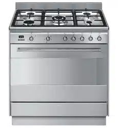
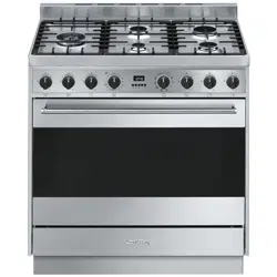
USER MANUAL 90cm Freestanding Dual Fuel Oven/Stove
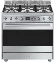
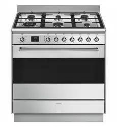
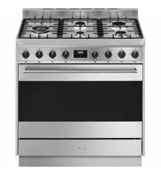
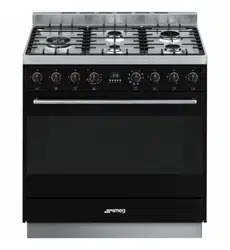
Description
General Description
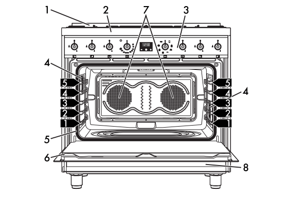
1 Backguard 6 Door
2 Cooktop 7 Fan
3 Control panel 8 Storage compartment
4 Oven light  Rack/tray support frame shelf
5 Seal
Cooktop
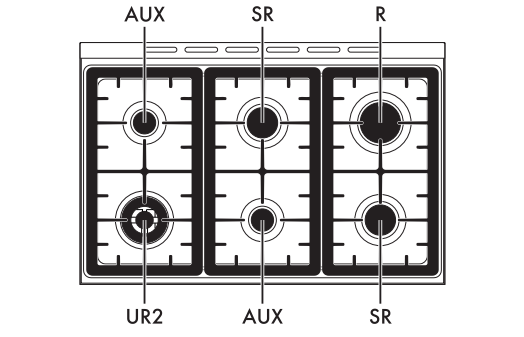
AUX = Auxiliary
SR = Semi-rapid
R = Rapid
UR2 = Ultra rapid
Control panel
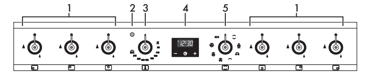
1 Cooktop burner knobs
- Useful for lighting and adjusting the cooktop burners.
- Press and turn the knobs anti-clockwise to the value
 to light the relative burners. Turn the knobs to the zone between the maximum and minimum
  setting to adjust the flame.
- Return the knobs to the
 position to turn off the burners.
2 Indicator light
- The indicator light comes on to indicate that the oven is heating up. It turns off as soon as it reaches the set temperature. It flashes regularly to indicate that the temperature set inside the oven is kept constant.
3 Temperature knob
- This knob allows you to select the cooking temperature.
- Turn the knob clockwise to the required value, between the minimum and maximum setting.
4 Programmer clock
- Useful for displaying the current time, setting programmed cooking operations and programming the minute minder timer.
5 Function knob
- The oven's various functions are suitable for different cooking modes. After selecting the required function, set the cooking temperature using the temperature knob.
Use
Instructions
Escaping gas may cause an explosion.
If you smell gas or notice any faults in the gas installation:
- Immediately shut off the gas supply or close the gas cylinder valve.
- Immediately extinguish all naked flames and cigarettes.
- Do not use any light or appliance switches and do not pull any plugs out of sockets. Do not use any telephones or mobile phones within the building.
- Open windows and ventilate the room.
- Call the aftersales service or the gas supplier.
Abnormal operation
Any of the following are considered to be abnormal operation and may require service:
- Yellow tipping of the hotplate burner flame.
- Sooting up of cooking utensils.
- Burners not igniting properly.
- Burners failing to remain alight.
- Burners extinguishing whilst in operation.
- Gas valves with are difficult to turn.
In case the appliance fails to operate correctly, contact the Authorised Assistance Centre in your area.
First use
- Remove any protective film from the outside or inside of the appliance, including accessories.
- Remove any labels (apart from the technical data plate) from the accessories and from the oven cavity.
- Remove all the accessories from the appliance and clean them (see 4 Cleaning and maintenance). Heat the empty oven at the maximum temperature to burn off any residues left by the manufacturing process.
Using the accessories
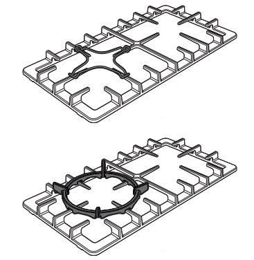
Ring reducers
The ring reducers have to be placed on the cooktop grids. Make sure they are placed properly.
Using the Teppanyaki plate (on some models only)
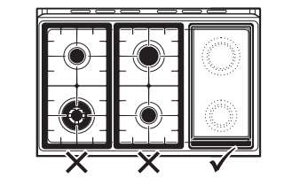
- The burners under the plate can be lit at the same time to the maximum setting for no more than 10 minutes. After this time they should be set at the minimum setting.
- After use, the burners must be turned off and left to cool for at least 60 minutes. The oven or ovens in the appliance on which the plate is used can be used together with the plate for a maximum of 60 minutes, while also following the indications provided in the instruction booklet.
- The same precautions should be followed even if only one burner is being used.
- After use, wait at least 15 minutes before removing the plate from the appliance.
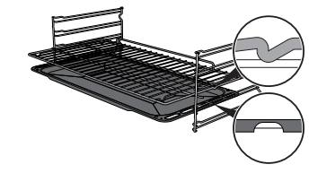
Racks and trays
Racks and trays have to be inserted into the side guides until they come to a complete stop.
- The mechanical safety locks that prevent the rack from being taken out accidentally have to face downwards and towards the oven back.
Rotisserie rod (on some models only)
- Insert the 4 supplied bushings in the 4 corner holes of the deep tray and screw them onto the ring nuts with a suitable tool (such as a screwdriver).
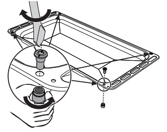
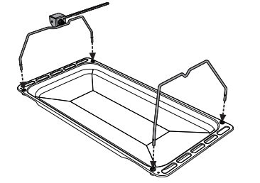
- Position the rotisserie supports in the bushings as shown in the figure below.
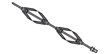
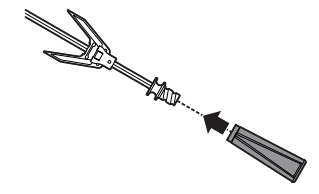
- Prepare the rotisserie rod with the food using the clip forks provided. The clip forks can be tightened using the fastening screws.
- Once you have prepared the rotisserie rod, place it on the supports. Insert the tip of the rod in the housing of the mechanism on the left-hand support until it stops.
- Place the tray on the first runner (see “General Description”).
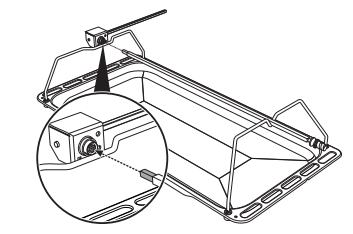
- Insert the tip of the rod in the rotisserie motor housing on the left of the rear wall of the oven.
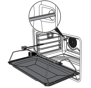
- To activate the rotisserie, turn the function knob to the
 position and set the cooking temperature using the temperature knob.
- When cooking is complete, remove the tray with the rotisserie.
- Screw on the handle provided so that you can handle the rotisserie rod more easily.
Cooking information table
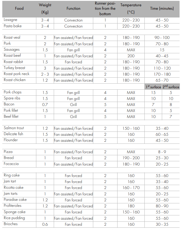
The times indicated in the table do not include preheating times and are provided as a guide only.
Cleaning and maintenance
Cleaning the appliance
Recommendations for cleaning the cooktop
- To keep the surfaces in good condition, they should be cleaned regularly after use. Let them cool first.
Cleaning the cooktop
- Pour some non-abrasive detergent on a damp cloth and wipe down the surfaces.
- Rinse thoroughly
- Dry with a soft cloth or a microfibre cloth.
Cleaning the cooktop grids, flamespreader crowns and burner caps
- Remove the components from the cooktop.
- Clean them with warm water and nonabrasive detergent. Make sure to remove any encrustations.
- Dry thoroughly with a soft cloth or a microfibre cloth.
- Replace the components on the cooktop
Teppanyaki plate (on some models only)
- The Teppanyaki plate is easier to clean when it is still lukewarm.
- Use conventional specific detergents for stainless steel and non-abrasive sponges. Any remaining encrustations or food residues can be easily removed by soaking the plate for a while. For very stubborn encrustations, we recommend using the supplied scraper. Dry it carefully.
Cleaning the igniters and thermocouples
- If necessary, clean the igniters and thermocouples with a damp cloth.
- If there is any dry residue, remove it with a toothpick or needle.
Recommendations for cleaning the oven cavity
For the best oven upkeep, clean it regularly after having allowed it to cool. Avoid letting food residue dry inside the oven cavity, as this could damage the enamel. Take out all removable parts before cleaning. For easier cleaning, we recommend removing:
- The door
- The rack/tray support frames
- The oven seal.
Removing the door
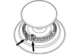
For easier cleaning, the door can be removed and placed on a tea towel. To remove the door proceed as follows:
- Open the door completely and insert two pins into the holes on the hinges indicated in the figure.
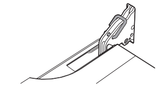
- Grasp the door on both sides with both hands, lift it forming an angle of around 30° and remove it.
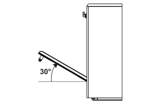
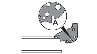
- To reassemble the door, put the hinges in the relevant slots in the oven, making sure that grooved sections A are resting completely in the slots. Lower the door and once it is in place remove the pins from the holes in the hinges.
Cleaning the door glazing
- The glass in the door should always be kept thoroughly clean. Use absorbent kitchen roll. In case of stubborn dirt, wash with a damp sponge and an ordinary detergent.
Installation
Clearances above and around domestic appliances
This appliance must be installed by an authorised person in accordance with this instruction manual, AS/NZS 5601.1 – Gas installations (installation and pipe sizing), local gas fitting regulations, local electrical regulations, Building Code of Australia and any other government authority.
Requirements
Requirements
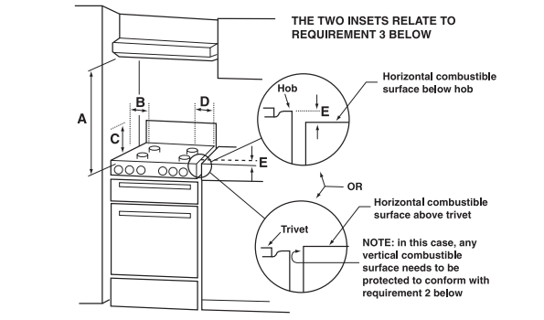
1. Overhead clearances – (Measurement A)
- Range hoods and exhaust fans shall be installed in accordance with the manufacturer’s instructions. However, in no case shall the clearance between the highest part of the cooktop of the cooking appliance and a range hood be less than 600 mm or, for an overhead exhaust fan, 750 mm. Any other downward facing combustible surface less than 600 mm above the highest part of the cooktop shall be protected for the full width and depth of the cooking surface area in accordance with Clause 5.12.1.2. However, in no case shall this clearance to any surface be less than 450 mm.
2. Side clearances – (Measurements B & C)
- Where B, measured from the periphery of the nearest burner to any vertical combustible surface, is less than 200 mm, the surface shall be protected in accordance with Clause 5.12.1.2 to a height C of not less than 150 mm above the cooktop for the full dimension (width or depth) of the cooking surface area. Where the cooking appliance is fitted with a ‘splashback’, protection of the rear wall is not required.
3. Additional requirements for Freestanding and Elevated Cooking Appliaces – (Measurements D & E)
- Where D, the distance from the periphery of the nearest burner to a horizontal combustible surface is less than 200 mm, then E shall be 10 mm or more, or the horizontal surface shall be above the trivet. See insets above.
Notes
- Requirement 3 does not apply to a freestanding or elevated cooking appliance which is designed to prevent flames or the cooking vessels from extending beyond the periphery of the appliance.
- The ‘cooking surface area’ is defined as that part of the appliance where cooking normally takes place and does not include those parts of the appliance containing control knobs.
- For definition of cooktop, see Clause 1.4.64.
- For definition of trivet, see Clause 1.4.109.
- Consideration is to be given to window treatments when located near cooking appliances. See Clause 5.3.4.
Gas connection
General informations
This appliance is suitable for installation with Natural Gas or ULPG (propane/butane). Refer to “Burner and nozzle characteristics table” section for the relevant burner pressure and appropriate injector sizes. When the appliance is to be connected to Natural Gas then the pressure regulator supplied must be fitted to the gas inlet. A test point (for checking the gas pressure) is supplied either with the regulator or as a separate fitting in the case of ULPG (propane) appliances.
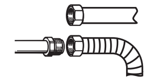
Connection of the appliance to the gas supply must be in accordance with the requirements of AS5601. A ½” BSP connector at the inlet is recommended and the gas supply line to the appliance must be of adequate length to allow sufficient withdrawal of appliance for service or disconnection and be:
- annealed copper pipe or;
- flexible hose according to AS/NZ1869 & be at least Class “B”, 10 mm diameter.
The appliance must be installed according to applicable provisions to allow the gas to be turned off and disconnected for servicing and removal of the appliance as required from the gas supply company. Before the appliance is operated make certain all relevant parts are placed in the correct position.
On completion of the installation, the installer MUST check for gas leaks and test each burner individually for the correct flame. Once all burners have been tested individually, turn all burners on together. Warranty service calls do not cover these adjustments!
To check the operating pressure of the appliance it is recommended at least 2 large size burners are used. Ensure appliance is secured to wall when installation is completed.
N.G. The regulator supplied must be fitted to the ½ BSP thread at the rear of the appliance. An approved manual shut-off valve must be installed. The N.G. regulator must be checked and adjusted to 1.0kPa after installation.
U.L.P.G. Can be connected to the inlet fitting directly. The pressure must be checked to ensure it is operating at 2.75kPa. A separate test point fitting must be installed between the piping & the appliance for the pressure to be checked to ensure it is operating at 2.75kPa.
Adaptation to different types of gas
In case of operation with other types of gas, the burner nozzles must be changed and the minimum flame adjusted on the gas cocks.
Replacing nozzles
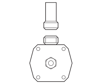
- Remove the pan stands, burner caps and flame-spreader crowns to access the burner casings.
- Replace the nozzles using a 7 mm socket wrench according to the gas to use (see “Burner and nozzle characteristics table”).
- Replace the burners in the correct position
Adjusting the minimum setting for natural or city gas
- Light the burner and turn it to the minimum position. Extract the gas cock knob and turn the adjustment screw next to the cock rod (depending on the model) until the correct minimum flame is achieved.
- Refit the knob and verify that the burner flame is stable.
- Turn the knob rapidly from the maximum to the minimum setting: the flame should not go out. Repeat the operation on all gas cocks.

Electrical connection
General information
- Check the grid characteristics against the data indicated on the plate.
- The identification plate bearing the technical data, serial number and brand name is visibly positioned on the appliance.
- Do not remove this plate for any reason. Perform the ground connection using a wire that is 20 mm longer than the other wires.
The appliance can work in the following modes:
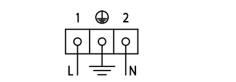
use a 3 x 1,5 mm² three-core cable.
Fixed connection
- Fit the power line with an omnipolar circuit breaker in compliance with installation regulations. The circuit breaker should be located near the appliance and in an easily reachable position.
Connection with plug and socket
- Make sure that the plug and socket are of the same type.
- Avoid use of adapters and shunts as these could cause overheating and a risk of burns.
For the installer
- The plug must remain accessible after the installation is complete. Do not kink or trap the mains connection cable.
- The appliance must be fitted according to the installation diagrams.
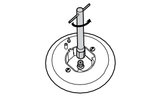
- Do not attempt to turn or stress the threaded elbow on the manifold. You risk damage to this part of the appliance which may void the manufacturer’s warranty.
- Before leaving check all connections for gas leaks with soap and water. DO NOT use a naked flame for detecting leaks
- Ignite all burners individually and concurrently to ensure correct operation of the gas valves, burner and ignition.
- Turn the gas knobs to the low position and observe stability of the flame for each burner individually and all together.
- In case the appliance fails to operate correctly after all checks have been carried out, refer to the Authorised Assistance Centre in your area.
- When satisfied with the appliance, please instruct the user on the correct method of operation.