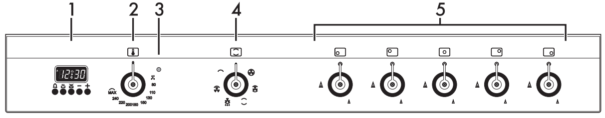
Useful for displaying the current time, setting programmed cooking operations and programming the minute minder timer.
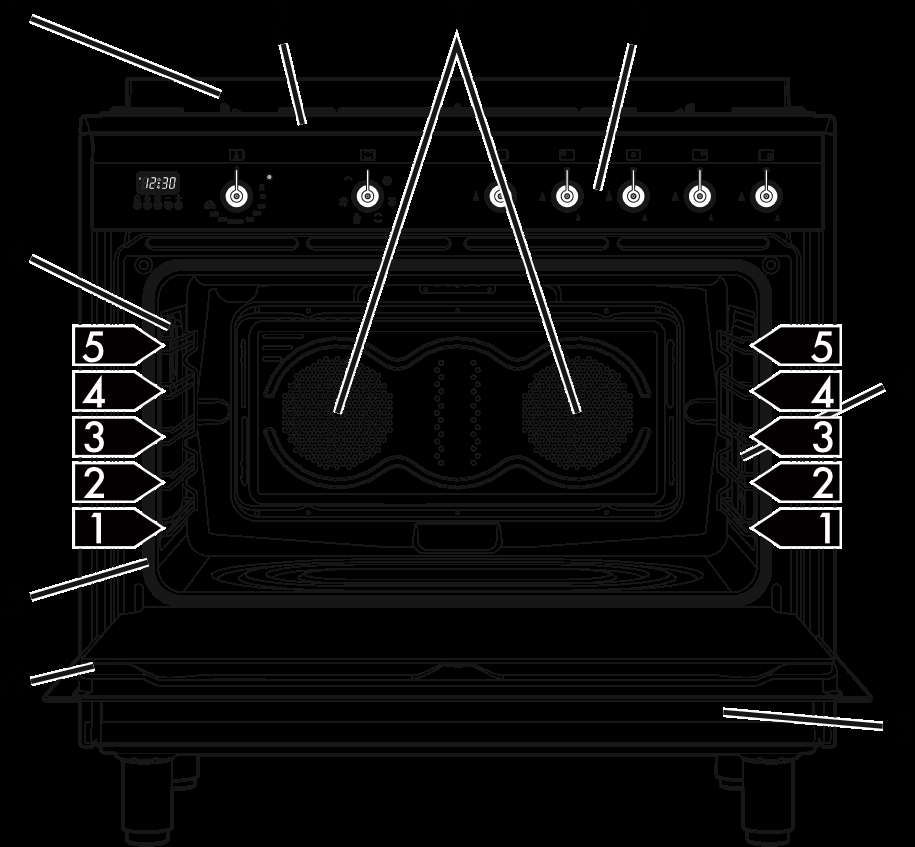
2. Temperature knob
This knob allows you to select the cooking temperature. Turn the knob clockwise to the required value, between the minimum and maximum setting.
3. Indicator light
The indicator light comes on to indicate that the oven is heating up. It turns off as soon as it reaches the set temperature. It flashes regularly to indicate that the temperature set inside the oven is kept constant.
4. Function knob
The oven's various functions are suitable for different cooking modes. After selecting the required function, set the cooking temperature using the temperature knob.
5. Cooktop burner knobs
Useful for lighting and adjusting the cooktop burners. Press and turn the knobs anti-clockwise to the value to light the relative burners. Turn the knobs to the zone between the maximum and minimum setting to adjust the flame. Return the knobs to the position to turn off the burners.
Other parts
Shelves
The appliance features shelves for positioning trays and racks at different heights. The insertion heights are indicated from the bottom upwards (see 2.1 General Description).
Cooling fan
The fan cools the oven and comes into operation during cooking. The fan causes a steady outflow of air from above the door which may continue for a brief period of time even after the appliance has been turned off.
Interior lighting
The appliance interior lighting comes on:
• When the door is opened
• When any function is selected.
Available accessories
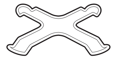
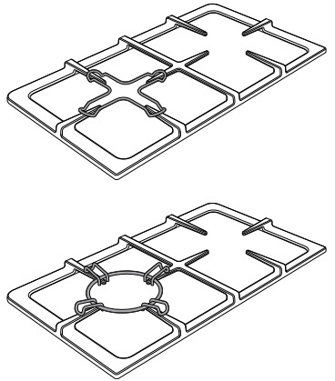
Ring reducer
Useful when using small cookware.
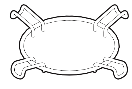
WOK ring
Useful when using a wok.
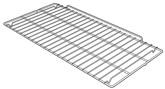
Rack
Useful for supporting containers with food during cooking.
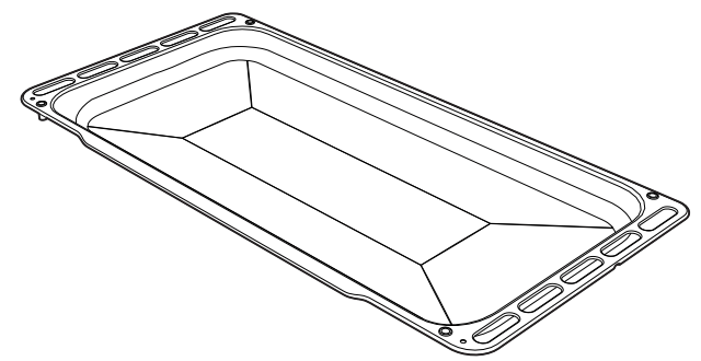
Oven tray
Useful for collecting fat from foods placed on the rack above.
Use
First use
1. Remove any protective film from the outside or inside of the appliance, including accessories.
2. Remove any labels (apart from the technical data plate) from the accessories and from the oven cavity.
3. Remove all the accessories from the appliance and clean them (see 4 Cleaning and maintenance). Heat the empty oven at the maximum temperature to burn off any residues left by the manufacturing process.
Using the accessories
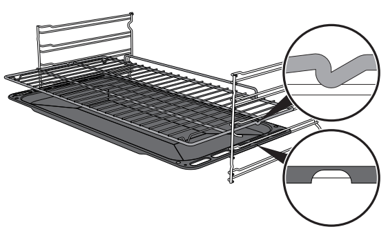
Racks and trays
Racks and trays have to be inserted into the side guides until they come to a complete stop
• The mechanical safety locks that prevent the rack from being taken out accidentally have to face downwards and towards the oven back.
Ring reducers
The ring reducers have to be placed on the cooktop grids. Make sure they are placed properly
Using the cooktop
All the appliance's control and monitoring devices are located together on the front panel. The burner controlled by each knob is shown next to the knob. The appliance is equipped with an electronic ignition device. Simply press the knob and turn it anticlockwise to the maximum flame symbol, until the burner lights. If the burner does not light in the first 15 seconds, turn the knob to and wait 60 seconds before trying again. After lighting, keep the knob pressed in for a few seconds to allow the thermocouple to heat up. The burner may go out when the knob is released: in this case, the thermocouple has not heated up sufficiently. Wait a few moments and repeat the operation. Keep the knob pressed in longer.
Correct positioning of the flamespreader crowns and burner caps
Before lighting the cooktop burners, make sure that the flame-spreader crowns are correctly positioned in their housings with their respective burner caps. Make sure that the holes in the flame-spreader crowns 1 are aligned with the thermocouples 2 and igniters 3.
Practical tips for using the cooktop
For better burner efficiency and to minimise gas consumption, use pans with lids and of suitable size for the burner, so that flames do not reach up the sides of the pan. Once the contents come to the boil, turn down the flame far enough to ensure that the liquid does not boil over.
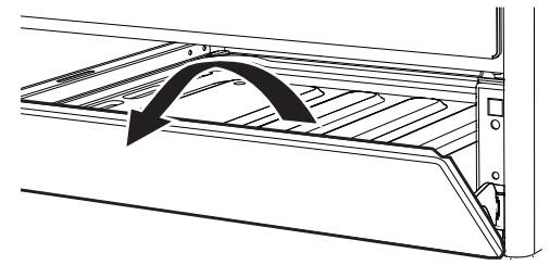
Using the storage compartment
The storage compartment is at the bottom of the cooker. To open it, pull the handle towards you. It can be used to store cookware or metallic objects necessary when using the appliance.
Using the oven
Switching on the oven To switch on the oven:
1. Select the cooking function using the function knob.
2. Select the temperature using the temperature knob.
Preheating stage
Cooking functions are always preceded by a preheating stage, which allows the appliance to heat up to cooking temperature. The indicator light comes on to indicate that the oven is heating up. The indicator light turns off to indicate that the food can be placed inside the oven and cooking will start automatically
Functions list
Fan forced
The combination of the fan and the circular heating element (incorporated in the rear of the oven) allows you to cook different foods on several levels, as long as they need the same temperatures and same type of cooking. Hot air circulation ensures instant and even distribution of heat. It will be possible, for instance, to cook fish, vegetables and biscuits simultaneously (on different levels) without odours and flavours mingling.
Fan assisted
The operation of the fan, combined with traditional cooking, ensures consistent cooking even with complex recipes. Perfect for biscuits and cakes, even when simultaneously cooked on several levels. (For multiple-level cooking, we recommend using the 2nd and 4th shelf).
Convection
As the heat comes from above and below at the same time, this system is particularly suitable for certain types of food. Traditional cooking, also known as convection cooking, is suitable for cooking just one dish at a time. Perfect for all types of roasts, bread and cakes, and in any case, particularly suitable for fatty meats such as goose and duck.
Baker’s function
The combination of the fan with just the lower heating element allows cooking to be completed more rapidly. This system is recommended for sterilising or for finishing off the cooking of foods which are already well-cooked on the surface, but not inside, which therefore need a little more heat. Perfect for any type of food.
Fan grill
The air produced by the fan softens the strong heatwave generated by the grill, grilling perfectly even very thick foods. Perfect for large cuts of meat (e.g. pork hock).
Grill
The heat coming from the grill element gives perfect grilling results above all for thin and medium thickness meat and, in combination with the rotisserie (where fitted), gives the food an even browning at the end of cooking. Perfect for sausages, spare ribs and bacon. This function enables large quantities of food, particularly meat, to be grilled evenly.
Vapour Clean
This function makes cleaning easier using the steam produced by a small quantity of water poured onto the appropriate groove placed on the bottom.
Cooking advice
General advice
• Use a fan assisted function to achieve consistent cooking at several levels.
• It is not possible to shorten cooking times by increasing the temperature (the food could be overcooked on the outside and undercooked on the inside).
Advice for cooking meat
• Cooking times vary according to the thickness and quality of the food and to consumer taste.
• Use a meat thermometer when roasting meat, or simply press on the roast with a spoon. If it is hard, it is ready; if not, it needs another few minutes cooking
Advice for cooking with the Grill and the Fan grill
• Meat can be grilled even when it is put into the cold oven or into the preheated oven if you wish to change the effect of the cooking.
• With the Fan grill function, we recommend that you preheat the oven before grilling.
• We recommend placing the food at the center of the rack.
• With the Grill function, we recommend that you turn the temperature knob to the maximum value near the symbol to optimise cooking.
• Foods should be seasoned before cooking. Foods should also be coated with oil or melted butter before cooking.
• Use the oven tray on the first bottom shelf to collect fluids produced by grilling.
• Grilling processes should never last more than 60 minutes.
Advice for cooking desserts/pastries and biscuits
• Use dark metal moulds: they help to absorb the heat better.
• The temperature and the cooking time depend on the quality and consistency of the dough.
• To check whether the dessert is cooked right through: at the end of the cooking time, put a toothpick into the highest point of the dessert. If the dough does not stick to the toothpick, the dessert is cooked.
• If the dessert collapses when it comes out of the oven, on the next occasion reduce the set temperature by about 10°C, selecting a longer cooking time if necessary.
• While cooking desserts or vegetables, excessive condensation may form on the glass. In order to avoid this, open the door very carefully a couple of times while cooking.
Advice for defrosting and proving
• Place frozen foods without their packaging in a lidless container on the first shelf of the oven.
• Avoid overlapping the food.
• To defrost meat, use the rack placed on the second level and a tray on the first level. In this way, the liquid from the defrosting food drains away from the food.
• The most delicate parts can be covered with aluminium foil.
• For successful proving, a container of water should be placed in the bottom of the oven.
To save energy
• Stop cooking a few minutes before the time normally used. Cooking will continue for the remaining minutes with the heat which has accumulated inside the oven.
• Reduce any opening of the door to a minimum to avoid heat dispersal.
• Keep the inside of the appliance clean at all times.
Programmer clock
1. Minute minder timer key
2. Cooking duration key
3. End of cooking key
4. Value decrease key
5. Value increase key
Setting the time
On the first use, or after a power failure, the digits will be flashing on the appliance’s display.
1. Press the keys and at the same time. The dot between the hours and the minutes flashes.
2. The time can be set using the key or . Keep the key pressed in to increase or decrease rapidly.
3. Press the key or wait 5 seconds. The dot between the hours and the minutes stops flashing.
4. The symbol on the display indicates that the appliance is ready to start cooking.
Timed cooking
1. After selecting a cooking function and temperature, press the key . The display will show the digits and the symbol displayed between the hours and the minutes.
2. Use the key or to set the required minutes.
3. Wait approx. 5 seconds without pressing any key in order for the function to activate. The current time and the symbols and will appear on the display.
4. At the end of cooking the heating elements will be deactivated. On the display, the symbol turns off, the symbol flashes and the buzzer sounds.
5. To turn off the buzzer just press any key of the programmer clock.
6. Press the keys and at the same time to reset the programmer clock.
Programmed cooking
1. Set the cooking time as described in the previous point “Timed cooking”.
2. Press the key . The sum of the current time plus the pre-set cooking duration will appear on the display
3. Use the key or to set the required minutes.
4. Wait approx. 5 seconds without pressing any key in order for the function to activate. The current time and the symbols and will appear on the display.
5. At the end of cooking the heating elements will be deactivated. On the display, the symbol turns off, the symbol flashes and the buzzer sounds.
6. To turn off the buzzer just press any key of the programmer clock.
7. Press the keys and at the same time to reset the programmer clock
Deleting the set data
Press the keys and at the same time to reset the programs set. Then switch off the oven manually if cooking is in progress.
Minute minder timer
The minute minder timer can be activated at any time.
1. Press the key . The display shows the digits and the indicator light flashing between the hours and the minutes.
2. Use the key or to set the required minutes.
3. Wait approx. 5 seconds without pressing any key to finish setting the minute minder. The current time and the symbols and appear on the display.
Adjusting the buzzer volume
The buzzer volume can be set to 3 different levels. When the buzzer is in operation, press the key to change the setting
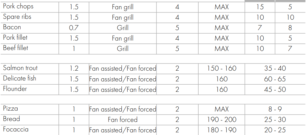
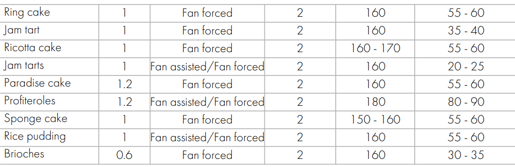
Cooking information table
The times indicated in the table do not include preheating times and are provided as a guide only
Cleaning and maintenance
Cleaning the appliance
Recommendations for cleaning the cooktop
To keep the surfaces in good condition, they should be cleaned regularly after use. Let them cool first.
Cleaning the cooktop
1. Pour some non-abrasive detergent on a damp cloth and wipe down the surfaces.
2. Rinse thoroughly.
3. Dry with a soft cloth or a microfibre cloth.
Cleaning the cooktop grids, flamespreader crowns and burner caps
1. Remove the components from the cooktop.
2. Clean them with warm water and nonabrasive detergent. Make sure to remove any encrustations.
3. Dry thoroughly with a soft cloth or a microfibre cloth.
4. Replace the components on the cooktop.
Cleaning the igniters and thermocouples
• If necessary, clean the igniters and thermocouples with a damp cloth.
• If there is any dry residue, remove it with a toothpick or needle.
Recommendations for cleaning the oven cavity
For the best oven upkeep, clean it regularly after having allowed it to cool. Avoid letting food residue dry inside the oven cavity, as this could damage the enamel. Take out all removable parts before cleaning.
For easier cleaning, we recommend removing:
• The door
• The rack/tray support frames
• The oven seal.
Removing the door
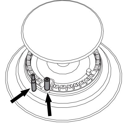
For easier cleaning, the door can be removed and placed on a tea towel. To remove the door proceed as follows:
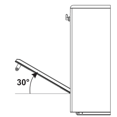
1. Open the door completely and insert two pins into the holes on the hinges indicated in the figure.
2. Grasp the door on both sides with both hands, lift it forming an angle of around 30° and remove it.
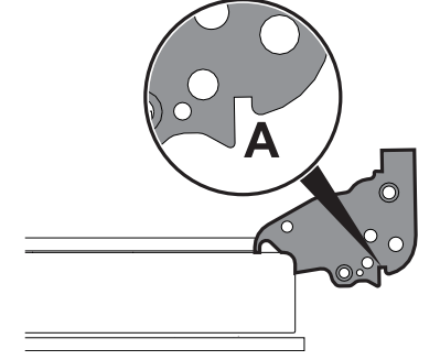
3. To reassemble the door, put the hinges in the relevant slots in the oven, making sure that grooved sections A are resting completely in the slots. Lower the door and once it is in place remove the pins from the holes in the hinges.
Cleaning the door glazing
The glass in the door should always be kept thoroughly clean. Use absorbent kitchen roll. In case of stubborn dirt, wash with a damp sponge and an ordinary detergent.
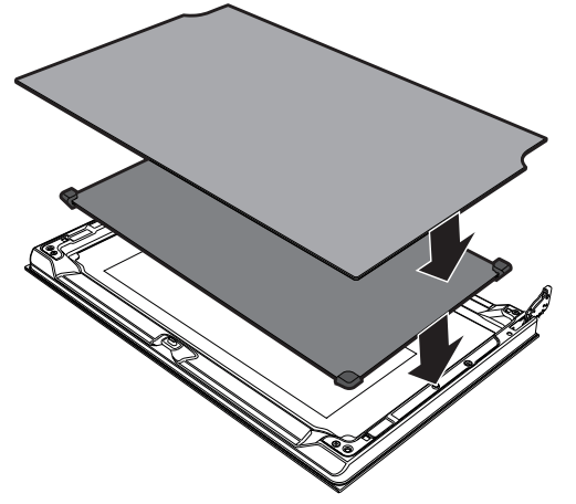
Removing the internal glass panes
For easier cleaning the door internal glass panes can be disassembled.
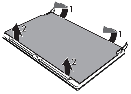
1. Remove the internal glass pane by pulling the rear part gently upwards, following the movement indicated by the arrows (1).
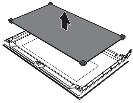
2. Then, pull the front part upwards (2). In this way, the 4 pins attached to the glass detach from their housings in the oven door.
3. Some models have an intermediate glass pane. Remove the intermediate glass pane by lifting it upwards.
4. Clean the external glass pane and the panes previously removed. Use absorbent kitchen roll. In case of stubborn dirt, wash with a damp sponge and neutral detergent.
5. Refit the panes in the reverse order in which they were removed.
6. Reposition the internal glass pane. Take care to centre and insert the 4 pins into their housings in the oven door by applying slight pressure.
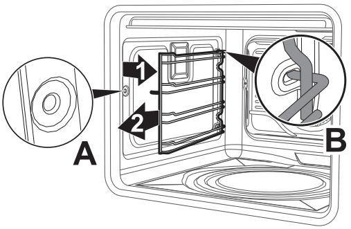
Removing racks/trays support frames
Removing the guide frames enables the sides to be cleaned more easily. This operation should be performed each time the automatic cleaning cycle is used (on some models only). To remove the guide frames: Pull the frame towards the inside of the oven to unhook it from its groove A, then slide it out of the seats B at the back. When cleaning is complete, repeat the above procedures to put the guide frames back in.
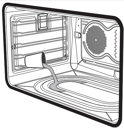
Vapour Clean
Preliminary operations
Before starting the Vapour Clean function:
• Completely remove all accessories from inside the oven.
• Pour approximately 40 cc of water into the tray. Make sure it does not overflow out of the cavity
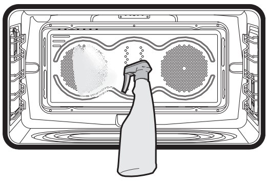
• Spray a water and washing up liquid solution inside the oven using a spray nozzle. Direct the spray against the side walls, upwards, downwards and towards the deflector.
• Close the door
Vapour Clean setting
1. Turn the function knob to the symbol and the temperature knob to the symbol .
2. Set a cooking time of 18 minutes using the programmer clock. The Vapour Clean cycle starts a few seconds after the last press on the programmer clock keys.
3. At the end of the Vapour Clean cycle, the timer will deactivate the oven heating elements, the buzzer will start to sound and the numbers on the programmer clock dial will flash.
End of the Vapour Clean cycle
4. Open the door and wipe away the less stubborn dirt with a microfibre cloth.
5. Use an anti-scratch sponge with brass filaments on tougher encrustations.
6. In case of grease residues use specific oven cleaning products.
7. Remove the water left inside the oven.
For improved hygiene and to avoid food being affected by any unpleasant odours, we recommend that the oven is dried using a fan assisted function at 160°C for approximately 10 minutes
Extraordinary maintenance
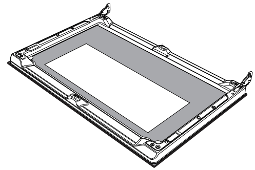
Removing and installing the oven seal
To remove the oven seal:
• Unhook the clips in the 4 corners and in the center, then pull the oven seal.
To install the oven seal:
• Hook the clips in the 4 corners and in the center onto the oven seal.
Oven seal maintenance tips
The seal should be soft and elastic. To keep the oven seal clean, use a nonabrasive sponge and lukewarm water to wash it.
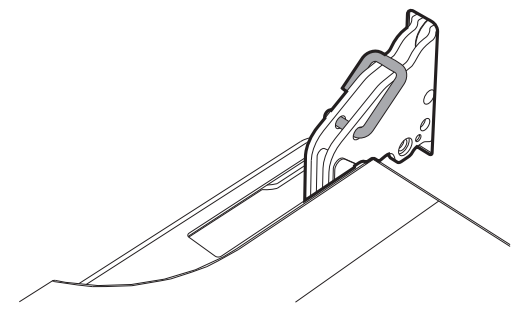
Replacing the oven light bulb
1. Completely remove all accessories from inside the oven.
2. Remove the racks/trays support frames.
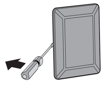
3. Remove the bulb cover using a tool (e.g. a screwdriver).
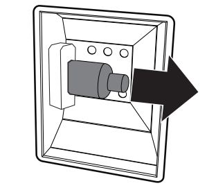
4. Slide out and remove the light bulb.
5. Fit the new light bulb.
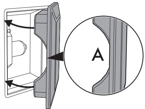
6. Refit the cover. Ensure the moulded part of the glass (A) is facing the door.
7. Press the cover completely down so that it attaches perfectly to the bulb support.
What to do if...
The appliance does not work.
• The circuit breaker is faulty: look in the fuse box and check that the circuit breaker is in working order.
• Power cut: check whether the kitchen light works.
The gas burner does not ignite.
• Power cut or damp ignition plugs: light the gas burner with a gas lighter or a match.
The oven does not heat up.
• Faulty fuse: check and, if required, replace the circuit breaker.
• The function knob has not been set: set the function knob.
All dishes that are prepared in the oven burn within an extremely short period of time.
• Faulty thermostat: call the Authorised Assistance Centres.
The door panel steams up when the oven is hot.
• Normal occurrence caused by the difference in temperature: this has no effect on oven performance.
Installation
Installation
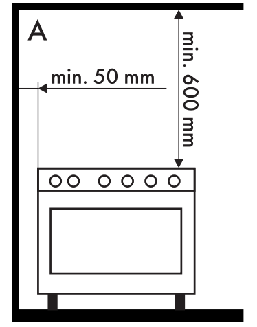
Clearances above and around domestic appliances
This appliance must be installed by an authorised person in accordance with this instruction manual, AS/NZS 5601.1 – Gas installations (installation and pipe sizing), local gas fitting regulations, local electrical regulations, Building Code of Australia and any other government authority
Requirements
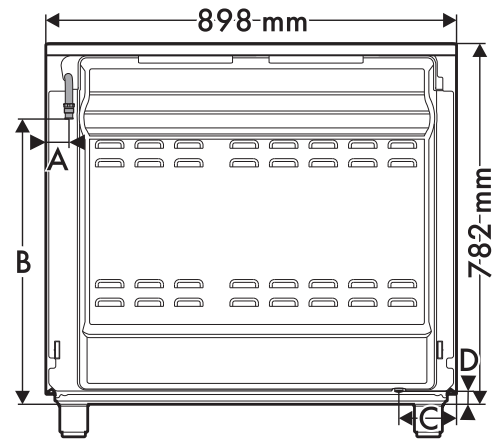
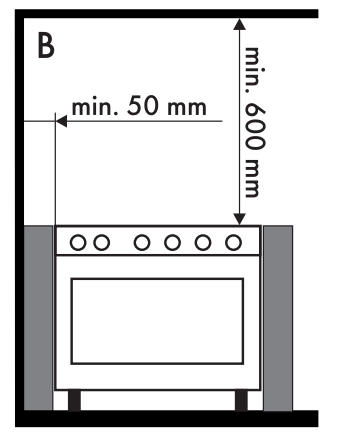
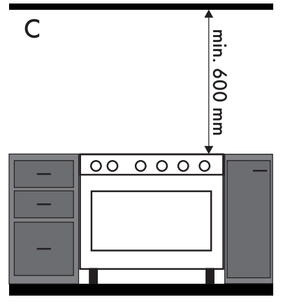
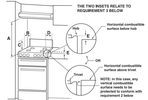
1. Overhead clearances – (Measurement A) Range hoods and exhaust fans shall be installed in accordance with the manufacturer’s instructions. However, in no case shall the clearance between the highest part of the cooktop of the cooking appliance and a range hood be less than 600 mm or, for an overhead exhaust fan, 750 mm. Any other downward facing combustible surface less than 600 mm above the highest part of the cooktop shall be protected for the full width and depth of the cooking surface area in accordance with Clause 5.12.1.2. However, in no case shall this clearance to any surface be less than 450 mm.
2. Side clearances – (Measurements B & C) Where B, measured from the periphery of the nearest burner to any vertical combustible surface, is less than 200 mm, the surface shall be protected in accordance with Clause 5.12.1.2 to a height C of not less than 150 mm above the cooktop for the full dimension (width or depth) of the cooking surface area. Where the cooking appliance is fitted with a ‘splashback’, protection of the rear wall is not required
3. Additional requirements for Freestanding and Elevated Cooking Appliaces – (Measurements D & E) Where D, the distance from the periphery of the nearest burner to a horizontal combustible surface is less than 200 mm, then E shall be 10 mm or more, or the horizontal surface shall be above the trivet. See insets above.
Notes
1. Requirement 3 does not apply to a freestanding or elevated cooking appliance which is designed to prevent flames or the cooking vessels from extending beyond the periphery of the appliance.
2. The ‘cooking surface area’ is defined as that part of the appliance where cooking normally takes place and does not include those parts of the appliance containing control knobs.
3. For definition of cooktop, see Clause 1.4.64.
4. For definition of trivet, see Clause 1.4.109.
5. Consideration is to be given to window treatments when located near cooking appliances. See Clause 5.3.4.
Gas connection
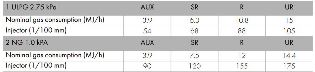
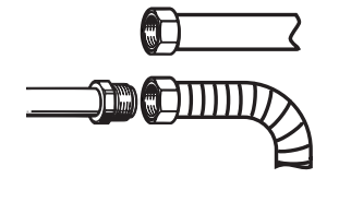
General informations This appliance is suitable for installation with Natural Gas or ULPG (propane/butane). Refer to “Burner and nozzle characteristics table” section for the relevant burner pressure and appropriate injector sizes. When the appliance is to be connected to Natural Gas then the pressure regulator supplied must be fitted to the gas inlet. A test point (for checking the gas pressure) is supplied either with the regulator or as a separate fitting in the case of ULPG (propane) appliances. Connection of the appliance to the gas supply must be in accordance with the requirements of AS5601. A ½” BSP connector at the inlet is recommended and the gas supply line to the appliance must be of adequate length to allow sufficient withdrawal of appliance for service or disconnection and be:
1. annealed copper pipe or;
2. flexible hose according to AS/NZ1869 & be at least Class “B”, 10 mm diameter.
The appliance must be installed according to applicable provisions to allow the gas to be turned off and disconnected for servicing and removal of the appliance as required from the gas supply company. Before the appliance is operated make certain all relevant parts are placed in the correct position. On completion of the installation, the installer MUST check for gas leaks and test each burner individually for the correct flame. Once all burners have been tested individually, turn all burners on together. Warranty service calls do not cover these adjustments!
To check the operating pressure of the appliance it is recommended at least 2 large size burners are used. Ensure appliance is secured to wall when installation is completed. N.G. The regulator supplied must be fitted to the ½ BSP thread at the rear of the appliance. An approved manual shut-off valve must be installed. The N.G. regulator must be checked and adjusted to 1.0kPa after installation. U.L.P.G. Can be connected to the inlet fitting directly. The pressure must be checked to ensure it is operating at 2.75kPa. A separate test point fitting must be installed between the piping & the appliance for the pressure to be checked to ensure it is operating at 2.75kPa
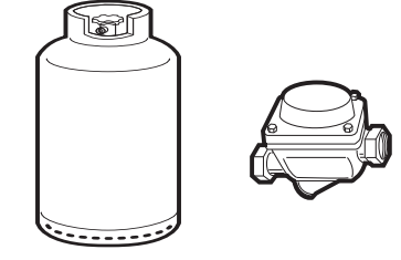
Connection to liquid gas
Use a pressure regulator and make the connection on the gas cylinder following the guidelines set out in the regulations in force. Make sure that the supply pressure complies with the values indicated in section “ Burner and nozzle characteristics table”.
Room ventilation
The room containing the appliance should have a permanent air supply in accordance with the standards in force. The room where the appliance is installed must have enough air flow needed for the regular combustion of gas and the necessary air change in the room itself. The cooktop shall be installed in rooms with natural ventilation, as required by Standards regulations AS/NZS5601.
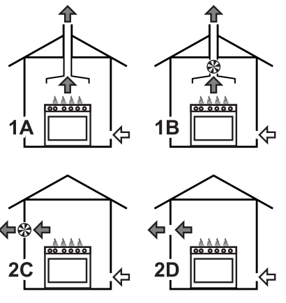
Combustion gas discharge
Combustion gases may be discharged by means of hoods connected to a flue with reliable natural draught, or a fan extraction system. An effective extraction system requires careful design by an authorised specialist, and must comply with the regulation distances and positions. After installation, the engineer must issue a certificate of compliance.
1. Extraction using a hood.
2. Extraction without a hood.
A. Single natural draught chimney.
B. Single chimney with extractor fan.
C. Directly outdoors with wall- or window-mounted extractor fan.
D. Directly outdoors through wall.
Air
Combustion products
Extractor fan
Adaptation to different types of gas
In case of operation with other types of gas, the burner nozzles must be changed and the minimum flame adjusted on the gas cocks.
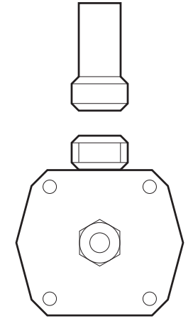
Replacing nozzles
1. Remove the pan stands, burner caps and flame-spreader crowns to access the burner casings.
2. Replace the nozzles using a 7 mm socket wrench according to the gas to use (see “Burner and nozzle characteristics table”)
3. Replace the burners in the correct position.
Adjusting the minimum setting for natural or city gas
Light the burner and turn it to the minimum position. Extract the gas cock knob and turn the adjustment screw next to the cock rod (depending on the model) until the correct minimum flame is achieved. Refit the knob and verify that the burner flame is stable.
Turn the knob rapidly from the maximum to the minimum setting: the flame should not go out. Repeat the operation on all gas cocks.
Adjusting the minimum setting for LPG
Tighten the screw located at the side of the cock rod clockwise all the way
Lubrication of gas cocks
Over time the gas cocks may become difficult to turn and get blocked. Clean them internally and replace the lubrication grease.
Burner and nozzle characteristics table
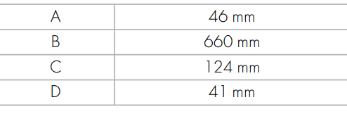
Overall dimensions
Location of gas and electrical connection points.
Positioning
General information
This appliance may be installed next to walls, one of which must be higher than the worktop, at a minimum distance of 50 mm from the side of the appliance, as shown in figures A and C relative to the installation classes. Any wall units positioned above the worktop must be at a minimum distance of at least 600 mm. If a hood is installed above the cooktop, refer to the hood instruction manual to ensure the correct clearance is left. Depending on the type of installation, this appliance belongs to classes:
A - Class 1 (Free-standing appliance)
B - Class 2 subclass 1 (Built-in appliance)
C - Class 2 subclass 1 (Built-in appliance)
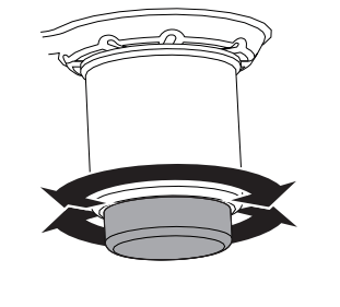
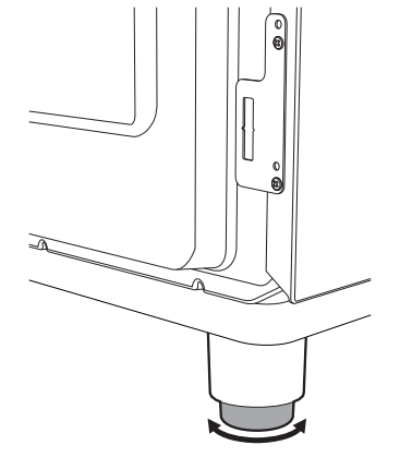
Positioning and levelling
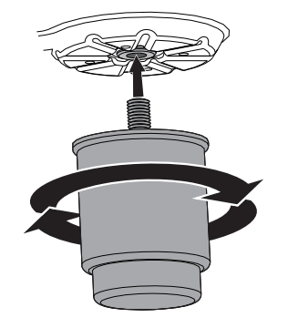
• After making the gas and electrical connections, screw on the four feet supplied with the appliance.
The appliance must sit level on the floor to ensure stability.
• Screw or unscrew the bottom part of the foot until the appliance is stable and level on the floor.
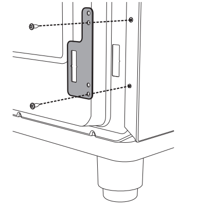
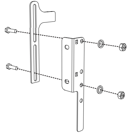
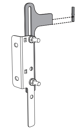
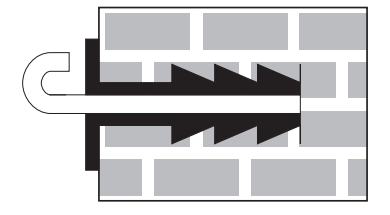
Fastening to the wall
1. Screw the wall fastening plate to the rear of the appliance.
2. Adjust the height of the 4 feet.
3. Assemble the fastening bracket.
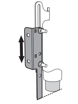
4. Align the base of the hook on the fastening bracket with the base of the slot on the wall fastening plate.
5. Align the base of the fastening bracket with the ground and tighten the screws to fix the measurements.
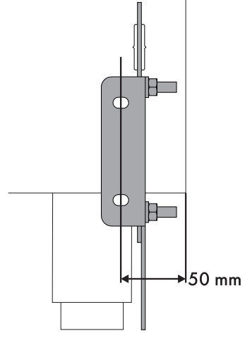
6. Use 50 mm for the distance from the side of the appliance to the bracket holes.
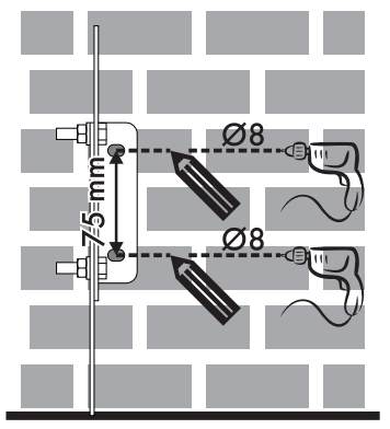
7. Move the bracket onto the wall and mark the position of the holes to be drilled in the wall.
8. After drilling the holes in the wall, use wall plugs and screws to fasten the bracket to the wall.
9. Push the cooker towards the wall, and at the same time, insert the bracket in the plate fastened to the rear of the appliance.
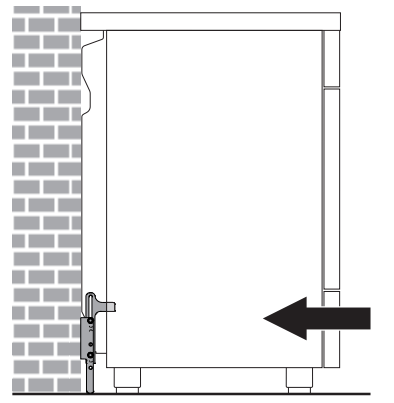
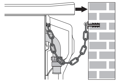
Wall fixing
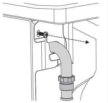
1. Turn the screw placed behind the cooktop near the gas connection.
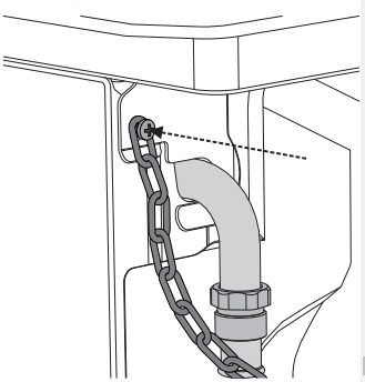
2. Attach the chain to the cooker with the screw just removed.
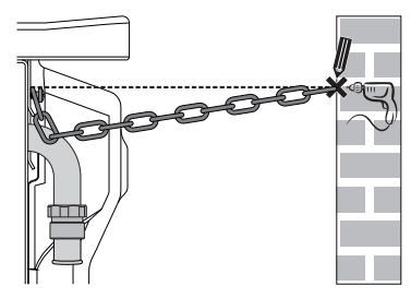
3. Stretch it out horizontally so that the other end of the chain touches the wall.
4. Mark the wall in the position where the hole is to be drilled.
5. Drill the hole and insert a wall plug
6. Attach the chain and push the appliance to the wall.
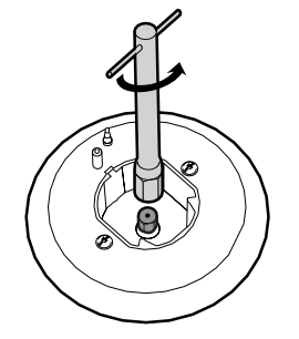
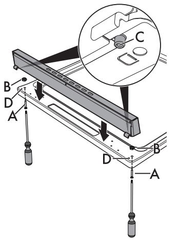
Assembling the upstand
The upstand must always be positioned and secured correctly on the appliance.
1. Unscrew the 2 nuts B on the back of the worktop.
2. Position the upstand above the worktop, taking care to align the pins C with the holes D.
3. Secure the upstand to the worktop by tightening the screws A.
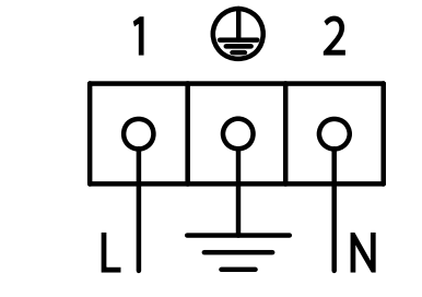
Electrical connection
General information
Check the grid characteristics against the data indicated on the plate. The identification plate bearing the technical data, serial number and brand name is visibly positioned on the appliance. Do not remove this plate for any reason. Perform the ground connection using a wire that is 20 mm longer than the other wires.
The appliance can work in the following modes:
• 220-240 V 1N~
use a 3 x 1,5 mm² three-core cable.
Fixed connection
Fit the power line with an omnipolar circuit breaker in compliance with installation regulations. The circuit breaker should be located near the appliance and in an easily reachable position.
Connection with plug and socket
Make sure that the plug and socket are of the same type. Avoid use of adapters and shunts as these could cause overheating and a risk of burns.
For the installer
• The plug must remain accessible after the installation is complete. Do not kink or trap the mains connection cable.
• The appliance must be fitted according to the installation diagrams.
• Do not attempt to turn or stress the threaded elbow on the manifold. You risk damage to this part of the appliance which may void the manufacturer’s warranty.
• Before leaving check all connections for gas leaks with soap and water. DO NOT use a naked flame for detecting leaks.
• Ignite all burners individually and concurrently to ensure correct operation of the gas valves, burner and ignition.
• Turn the gas knobs to the low position and observe stability of the flame for each burner individually and all together.
• In case the appliance fails to operate correctly after all checks have been carried out, refer to the Authorised Assistance Centre in your area.
• When satisfied with the appliance, please instruct the user on the correct method of operation.
 Rack/tray support frame shelf
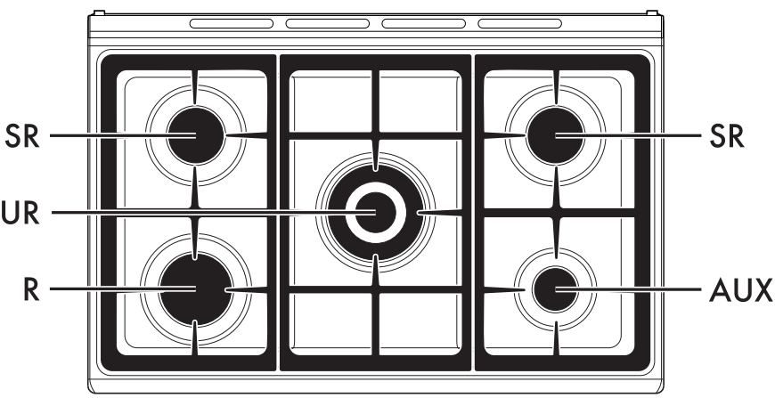
 the relative burners. Turn the knobs to the zone between the maximum
 setting to adjust the flame. Return the knobs to the
  position to turn off the burners.
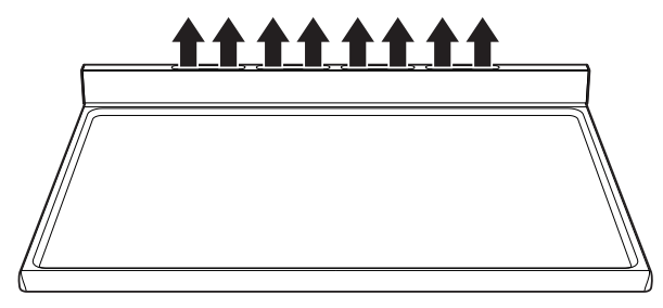
 and wait 60 seconds before trying again. After lighting, keep the knob pressed in for a few seconds to allow the thermocouple to heat up. The burner may go out when the knob is released: in this case, the thermocouple has not heated up sufficiently. Wait a few moments and repeat the operation. Keep the knob pressed in longer.
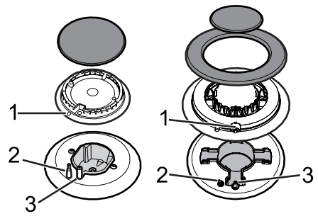
 Fan forced
 Fan assisted
 Convection
 Baker’s function
 Fan grill
 Grill
Grill Vapour Clean
 symbol to optimise cooking.
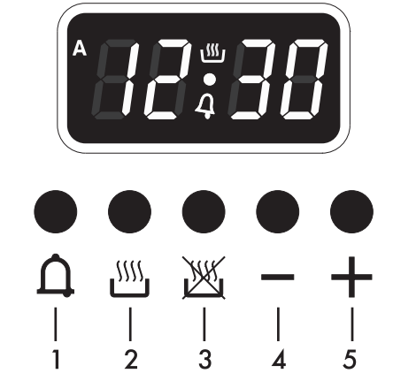
 will be flashing on the appliance’s display.
 and
and at the same time. The dot between the hours and the minutes flashes.
 or
or . Keep the key pressed in to increase or decrease rapidly.
 on the display indicates that the appliance is ready to start cooking.
 and
and . The display shows the digits
  flashing between the hours and the minutes.
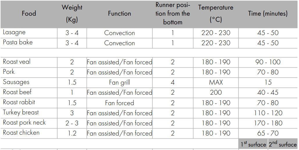
 and the temperature knob to the symbol
 .
.
 Air
Air Combustion products
 Extractor fan