Loading ...
Loading ...
Loading ...
Ice Maker Performance Mode Instructions (cont’d)
Please read the following installation methods before using, and choose the correct drain mode for
your situation. Set up your ice maker accordingly.
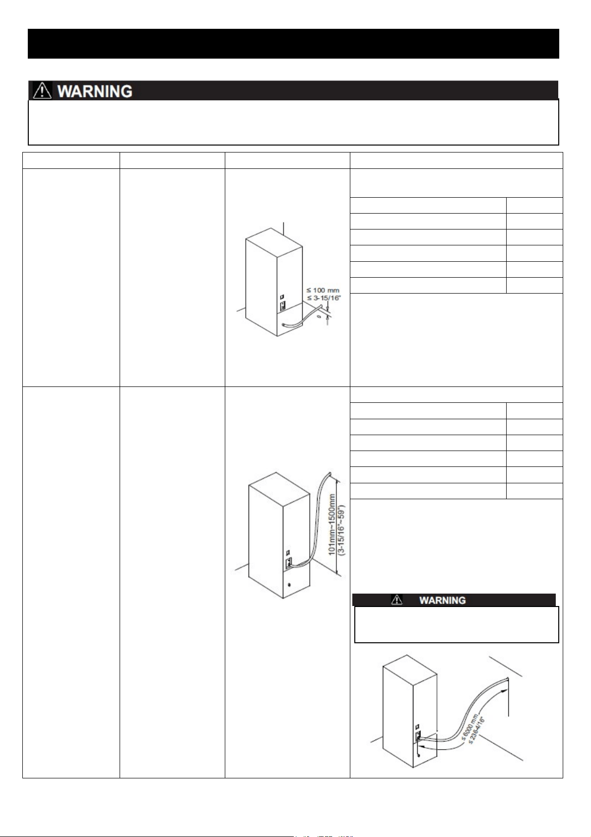
Performance Mode Instructions Suitable situation Operation instruction
Direct drainage
mode
(Recommended
mode)
Excess water
will be drained off
by the outlet water
pipe on the back of
the unit
The height of drain hole
in the room
≤100 mm (3-15/16”)
Ref.: Fig. A, Fig. B & Fig. C
Screw Nut and Switch
Condition
screw nut(front) (3) + seal washer(front) (4)
lock
screw nut(back) (7) + seal washer(back) (6)
open
screw nut for valve seal (11)
lock
screw nut for valve seal (12)
open
force water outlet switch (8)
OFF
1. Please be sure the screw nut and switch are in the
above condition;
2. Use a certain length drain pipe,connect one side to
the direct water outlet pipe connection (13), the
other to the drain hole. Please be sure the
connection is tight to avoid water leakage.
Drain pump mode
(Recommended
mode)
Excess water
will be forced to drain
out by the pump on
back of the unit.
The height of drain
hole in the room is
between
101 mm~1500 mm
(3-15/16”~59”)
Ref.: Fig. A, Fig. B & Fig. C
Screw Nut and Switch Condition
screw nut(front) (3) + seal washer(front)(4)
lock
screw nut(back) (7) + seal washer(back) (6)
open
screw nut for valve seal (11)
open
screw nut for valve seal (12)
lock
force water outlet switch (8)
ON
1. Please be sure the screw nut and switch are in the
above condition;
2. Use a certain length drain pipe, connect one side to
the force water outlet pipe connector (10), the other
to the drain hole. Please be sure the connection is
tight to avoid water leakage.
The lengthen of drainpipe is no more than 6000 mm
(236-4/16”) in order to prevent slops return.
7
INSTALLATION INSTRUCTIONS
Loading ...
Loading ...
Loading ...