If you are receiving the unit from a transportation company, it is customer’s obligation to inspect thepackage and note any damage on the delivery receipt. After delivery, have your induction cooktop carefully unpacked, and again check forany visible damage. If you find any damage onthe unit at this point, immediately inform your dealer or distributor. Although the responsibility for shipping lies with the carrier, your dealer/ distributor will assist you with your claim.
If the unit is not supposed to be installed for some time, you should keep it in its original packaging, stored in a dry and safe place. Read through the section of this manual which pertains to installation, and make sure that all of the requirements can be provided or are already provided. Ensure that your electric power supply is correct.
Before you install the unit, you should take a moment to write down the information from your nameplate and fill-out the table on page 19, for future after-sale servicing needs. This information will be required every time you call for any service on your unit.
Installation
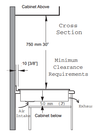
To install the cooktop, cut out a rectangular opening in the counter as shown on the drawing and table below. Also, ensure that you have a minimum of 10 mm (3/8”) of space in the back of the unit, between the rim and backsplash on your counter (or wall if no backsplash) for ventilation. A self-adhesive gasket is supplied with your unit. Before setting the cooktop in place install this gasket by sticking it underneath the rim.
Apply the gasket only along the front rim and on both sides. This gasket will prevent most of the spills from entering the cabinet below and will keep the unit in place. Once the gasket is installed, place the cooktop in the opening, and lay it on the rim. Do this carefully - do not drop the unit into the cutout. Make sure that the unit is sitting properly on its rim all around the perimeter.
Other Installation Requirements
During cooking, built-in fan inside the cooktop will operate constantly to keep the internal components cool. The air intake is on the bottom of the cooktop box, and the warm air exhaust is located on the front of the rim, as shown on the schematic. If the air intake or the exhaust is obstructed, the cooktop safeties will either diminish the power output or shut down the unit.
We suggest that you should periodically check that there are no objects (dust, paper,etc.) which could obstruct the air inlet under your induction cooktop.
Although induction-cooktop heat rejection is minimal and the unit does not create any fumes in operation, such unit must be installed underneath a properly sized ventilation hood for exhausting any smell, vapor and smoke created by cooking itself.
Also, a proper downdraft system can be used for ventilation.
A minimum vertical clearance of 750 mm [30”] is required between the top of the cooking surface and the bottom of any unprotected combustible material, such as cabinets, wooden trim etc.
In the back, leave a minimum of 10 mm [3/8”] between the cooktop edge and adjacent vertical surfaces (backsplash, wall, high cabinets etc.). This space is needed for the unit to breath properly.
If a downdraft ventilation system is used, a minimum of 6 mm (1/4”) of clearance is required between the rear edge of the cooktop and the downdraft snorkel.
Leave a minimum of 50 mm [2”] underneath the unit for the air intake.
Your cook-top must always breath adequately. Make sure that the air inlet and its exhaust are not obstructed.
The unit must not be installed above a washing machine, a refrigerator or a deepfreezer box
To eliminate the risk of burns or fire by reaching over heated surface units, cabinet storage space located above the surface units should be avoided.
The unit must be installed such that it can be pulled without difficulty out of the cut-out for servicing or cleaning.
Never glue, silicone or wedge the unit inside its cut-out.
Maximum power output .............................................. 7200 W 30A
Connect to .............. 240 V, 60 Hz, 2 Pole+G, 40
A minimum supply, (3 conductors #10 AWG)
Electrical wiring information
An adequate electrical supply must be provided for this unit. All wire connections and grounding must be done in accordance with local electrical codes, or if these codes are not established, then with the National Electrical Code, ANSI/NFPA No. 70 in the US , or with the Canadian Electrical Code, CAN/CSA C22.1, in Canada.
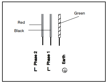
This unit comes equipped with three connection wires in a flexible conduit. The conduit must be routed and properly connected to an approved, owner-supplied, electrical, wall junction-box. An approved connector must be used for connecting the conduit to the junction box. A three wire, 2 poles, 240 V, 60 Hz service with minimum 40 A circuit protector must be provided. The red and the black wire from the unit are to be connected to the service (”hot”) wires, and the green wire is to be connected to the ground conductor.
The circuit protector for the unit should be properly marked inside electric panel and anybody using the unit, or technician servicing the unit, should be advised of circuit protector’s location, so that the power to the unit can be disconnected when necessary.
Once the unit is properly fitted and connected to the electrical power supply, turn the unit on to ensure that all elements and controls are operating well.
Note that your unit is designed for a stabile and steady 240 V supply and the manufacturer, its distributors and dealers cannot be held
•240 V
Connect the 3 wires as per the following colour code
responsible for any unit malfunction due to an inadequate electrical supply (inadequate cable size, low voltage, power surge etc). Furthermore, if your residence has only a 208 V supply system, and if the voltage frequently fluctuates, your cooktop may not function properly
It is recommended that the connection to electrical supply is done by a qualified electrician.
If there is any visible physical damage on the conduit and the wires, the unit must not be connected to the mains. A qualified electrician or approved service agent should be called in to replace the wires and the conduit
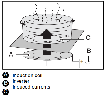
Principle of Induction
When an induction element - also called: ‘a heating zone’, or simply: ‘a coil’ - is switched on, the appropriate utensil is used, and a desired level of heating power selected, the electronic circuit unit (‘induction generator’ or ‘inverter’) powers up the induction coil which creates a magnetic field. This magnetic field continuously changes in terms of frequency and intensity, and this creates induced currents in the bottom of the utensil and ultimately results in heat. The heat is transferred directly to the food being cooked.
Thus, induction heat makes the utensil a direct source of heat, featuring high level of efficiency with extremely low energy loss and unparalleled heating level control.
With induction cooking there is very little ‘heating inertia’. Induction cooking elements do not incorporate a heat generating element - unlike convectional electric rings, halogen or radiant elements etc. - therefore, heat levels can be changed very quickly.
Energy efficiency for induction is within range of 90-95%, compared with 55-65% for conventional and radiant element, or 45% - 55% for gas fueled burners. The energy efficiency contributes to substantial energy savings, both beneficial to the owner as well as the environment.
Induction cooking elements are sensitive to the utensil type being used :
- if there is no utensil placed on the coil, or if the utensil is not of induction grade, there will be no power emitted by the coil;
- if the utensil is placed partially on the coil, or if it is smaller than the coil, the internal sensors will reduce power to the coil; The Principle of Induction
- if the utensil is fully removed from the coil, the power output will be instantaneously reduced to ‘0’, and, eventually, the controls will turn the element off after a minute, unless the utensil is returned back onto the coil.
When compared to the other methods of cooking, induction cooking has a very low level of ambient heat, thus makes cooking more pleasurable, with a reduced need for ventilation.
Finally, the vitroceramic glass as a cooking surface barely becomes hot and this makes cleaning much easier.
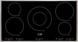
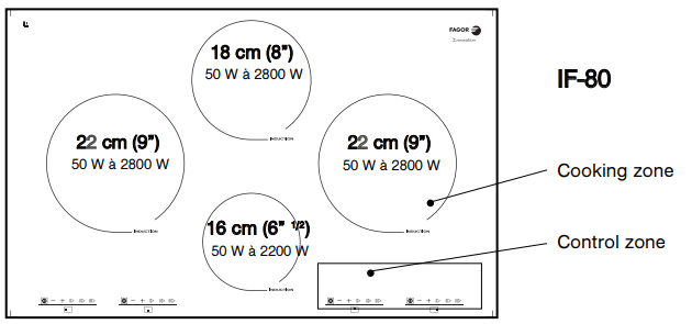
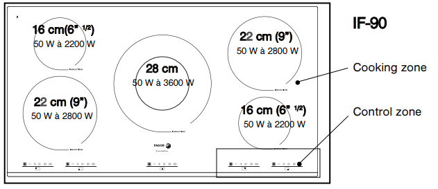
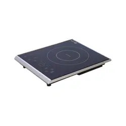
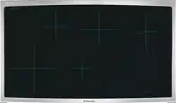
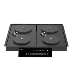
Glass Top, Coil Size and Controls
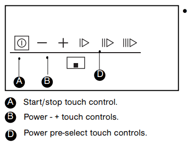
• DESCRIPTION OF THE CONTROL PANEL
• POWERING ON
Press the start/stop touch control for the zone you want to use. A flashing "0" indicates that the zone is on. You can then choose the desired power level.
If you do not select a power level, the cooking zone will automatically shut off.
• ADJUSTING THE POWER
Press the + or - power touch controls. or on pre-select touch controls.
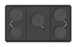
Tip : For simultaneous use, favour the use of cooking zones located on opposite sides of the hob. On the same side, the use of a cooking zone at maximum power results in an automatic limitation of the other cooking zone on that side, which is indicated in the power level display
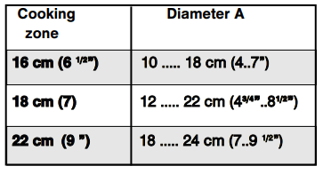
• WHICH COOKING ZONE SHOULD YOU USE BASED ON YOUR COOKWARE?
Tip : To check the suitability of your cookware: Place the vessel on a cooking zone at power level 4. If the display remains on, your cookware is compatible. If the display flashes, your cookware cannot be used with induction cooking. You can also use a magnet to test the cookware. If a magnet "sticks" to the bottom of the cookware, it is compatible with induction.
• POWER SHARING
Under the pretense that only one zone is used with an adequate utensil covering the whole surface of the coil, and that power on the zone is adjusted to the maximum (‘12’):
- the maximum power output of 22 cm (9”) heating zone is 2.8 kW;
- the maximum power output of 16 cm (6 1/2”) heating zone is 2.0 kW.
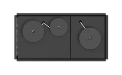
If only one coil is employed, it can be utilized at its maximum power, but as soon as the other coil is turned on, the controls adjust the power on both coils automatically for ‘power sharing’. This power sharing is administered by unit’s microprocessors, which will alternate power between the two elements. There are two factors affecting improved power sharing on your cooktops.
The first is the application of an improved technology for power sharing - not using common relays, but rather semiconductors which makes power sharing quicker, thus more efficient. The second factor is that, when in a power-sharing mode, two zones can share full, 3.6 kW, power output of the inverter.
Note that the controls will not allow both zones to operate at full power, and the power will be adjusted automatically - e.g. if the power on one zone is adjusted to a maximum, and the other zone is turned on and power level also adjusted to its maximum, the power level on the first zone will automatically become lower. This change will be visible on digital displays. The controls are set in such a manner that the last instruction (command) given to an element is always a priority
Utensils for Your Induction Unit
Induced current can be created only in materials which have magnetic properties. Thus, utensils for use with an induction unit must be made from a ferromagnetic material or have inserts with magnetic properties. Your household may already have cookware suitable for induction cooking, and you may test any utensil with an induction element. Incorporated controls are able to recognize a suitable utensil. To perform a utensil test:
- Turn an element on and adjust power to any level
- you will notice that the digital power display is flashing.
- Place your utensil on the coil. If the piece being tested is suitable for induction cooking, the display will become steady. However, if it keeps flashing, the utensil cannot be used on your induction unit.
- If the utensil is empty, remove it from the coil immediately after you have done test and turn the element OFF.
Another simple test to determine if a piece of cookware can be used on an induction cooktop is the ‘magnet test’. Use a magnet and place it on the utensil. If the magnet sticks to it, the piece will work with induction.
Utensils compatible with induction are:
• Cookware made of enamel coated steel with or without a non-stick coating.
• Cast iron cookware with or without enamel coated base.
• Stainless steel pots and pans designed for induction cookware.
Note: Stainless steel used for utensils is nonmagnetic, in most cases, and unsuitable for induction cooking, but most manufacturers make such utensils in layers for better heat distribution, and a good number of such pots and pans can be used with induction. To make sure if a stainless steel utensil can be used perform the utensil test.
Use of utensils with enameled coated base will prevent the glass top of your unit from getting scratched.
Pots and pans which do not have a flat bottom still may be used, however they should not be overly deformed.
Cookware made from glass, ceramic, earthenware, aluminum and copper pots and pans and non-magnetic stainless steel cookware are not suitable for induction cooking.
Matching Pots & Pans with Coils etc
Small elements,16 cm (6 1/2”), are best utilized:
- With small utensils - but normally not smaller then 10 cm (4”);
- For slow cooking and simmering (sauces, creams, etc.);
- For cooking small quantities of food. Large elements, 22 cm (9”), are primarily designed for day-to-day cooking needs and most commonly used pans - 18 to 25 cm (7 to 9 1/2”) in diameter.
To Do or Not to Do
You must:
- Always place your utensil such that its center is aligned with the centre of the coil.
- Avoid hitting the vitroceramic glass with utensils or any hard objects - the glass surface is highly resistant but not unbreakable.
- Pick-up your utensils when moving them around. Do not slide them and avoid excessive rubbing of the top, as this leaves scratches and erases the markings .
- Avoid using utensils with rough or deformed bottoms.
- Avoid leaving any metal cooking accessories, knives and forks, or metal objects on the hob. They may get hot if left close to any heating element in use.
- Avoid storing flammable products in the cabinets under your cooktop.
- Never leave an empty utensil on an induction heating element, even when the element is turned OFF.
- Only use maximum power for boiling and frying.
- Never try heating up a closed can.
- Avoid pre-heating your non-stick pans (e.g. with teflon coating) at maximum heat.
- Avoid storing solid and heavy items in the cabinets above your cooktop. They may unintentionally drop and damage the glass. To Do or Not To Do
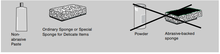
Daily Care Of Your Appliance
MAINTAINING YOUR APPLIANCE
TYPE OF STAINS/SPOTS
WHAT TO DO
ACCESSORIES or AGENTS EMPLOYED
Minor
Soak the area to be cleaned with soapy water, then wipe it.
Cleaning sponges & mild detergents
Accumulated burn-on stains.
Soak the area to be cleaned with warm soapy water. Use a special scraper for vitroceramic glass to remove grease and food particles. Finish off with a cleaning sponge, then wipe it clean.
Cleaning sponges, mild detergents and cleaning agents for vitroceramic glass
Rings and traces of lime scale.
Apply warm white vinegar on the stain. Leave to act then wipe off with a soft cloth. OR Use a commercial cleaner on affected area. Note that such cleaner may leave stains on stainless steel frame, thus protect exposed stainless steel.
Cleaning cloth,white vinegar, or diluted de-liming agent.
Burn-on stains following sugar spillage, melted aluminium or plastic.
Apply special vitroceramic glass cleaner on the surface, preferably one which contains silicone (protective action). Leave to act, then finish off with a cleaning sponge, then wipe it clean.
Vitroceramic cleaning agents and sponge.
Troubleshooting
PROBLEM
POSSIBLE CAUSES
WHAT SHOULD YOU DO?
When you switch the unit on, the supply-line breaker trips off or the supply-line fuse burn.
Your unit may be connected incorrectly,or there is an internal problem.
Have the connection checked first. If the connection is OK, contact your service agent.
When you switch elements on, only one element works.
There is an internal problem with the unit.
Contact your service agent.
The fans keep running for a few minutes after the unit has been switched off
The electronics are cooling down
This is a normal occurrence.
The top of the unit is always lukewarm (even when elements are not switched on)
The electronic components are under power and they create heat.
This is a normal occurrence.
Your hob makes faint clicking noise when in operation.
This noise occurs when the power is being shared between two induction coils.
This is a normal occurrence.
The unit doesn't work at all.
There may be a power supply or internal problem.
Check your beakers (fuses) and/or connection cable. If OK, contact your service agent.
After turning an element ON and having utensil placed on the coil, there is no heat and the digital indicator continues flashing..
The utensil you are trying to use is not compatible with induction cooking or its diameter is under 10 cm. (4”).
Use another utensil suitable for induction cooking.
Utensil makes noise during cooking
Your utensil creates noise from vibrations caused by induced current .
Under high power this phenomenon is normal with some types of pots and pans. There is no danger for the hob.
The hob gives off a smell when first used for cooking
A new unit
Use each heating element for an hour with a pan filled with water.