INSTALLATION MANUAL
AIR CONDITIONER
• Please read this installation manual completely before installing the product.
• Installation work must be performed in accordance with the national
wiring standards by authorized personnel only.
• Please retain this installation manual for future reference after reading
it thoroughly.your set and retain it for future reference.
P/NO : MFL67221404
www.lg.com
MODELS : ARUN Series
ENGLISH FRANÇAIS
ESPAÑOL
2 Outdoor Unit
IMPORTANT!
CAUTION
: Improper installation, adjustment, alteration, service or maintenance can void the warranty.
The weight of the condensing unit requires caution and proper handling procedures when lifting
or moving to avoid personal injury. Use care to avoid contact with sharp or pointed edges.
Safety Precautions
• Always wear safety eye wear and work gloves when installing equipment.
• Never assume electrical power is disconnected. Check with meter and equipment.
• Keep hands out of fan areas when power is connected to equipment.
• R-410A causes frostbite burns.
• R-410A is toxic when burned.
NOTE TO INSTALLING DEALER: The Owners Instructions and Warranty are to be given to the owner
or prominently displayed near the indoor Furnace/Air Handler Unit.
When wiring:
Electrical shock can cause severe personal injury or death. Only a qualified,
experienced electrician should attempt to wire this system.
• Do not supply power to the unit until all wiring and tubing are completed or reconnected and checked.
• Highly dangerous electrical voltages are used in this system. Carefully refer to the wiring diagram and these
instructions when wiring. Improper connections and inadequate grounding can cause accidental injury or death.
• Ground the unit following local electrical codes.
•
•
Connect all wiring tightly. Loose wiring may cause overheating at connection points and a possible fire hazard.
The choice of materials and installations must comply with the applicable local/national or international standards.
When transporting:
Be careful when picking up and moving the indoor and outdoor units. Get a partner to help, and
bend your knees when lifting to reduce strain on your back. Sharp edges or thin aluminum fins on
the air conditioner can cut your finger.
When installing...
... in a wall: Make sure the wall is strong enough to hold the unit's weight.
It may be necessary to construct a strong wood or metal frame to provide added support.
... in a room: Properly insulate any tubing run inside a room to prevent "sweating" that can cause
dripping and water damage to wall and floors.
... in moist or uneven locatinons: Use a raised concrete pad or concrete blocks provide a solid,
level foundation for the outdoor unit. This prevents water damage and abnormal vibration.
... in an area with high winds: Securely anchor the outdoor unit down with bolts and a metal
frame. Provide a suitable air baffle.
... in a snowy area(for Heat Pump Model): Install the outdoor unit on a raised platform that is
higher than drifting snow. Provide snow vents.
When connecting refrigerant tubing
• Keep all tubing runs as short as possible.
• Use the flare method for connecting tubing.
• Check carefully for leaks before starting the test run.
When servicing
• Turn the power OFF at the main power box(mains) before opening the unit to check or repair
electrical parts and wiring.
• Keep your fingers and clothing away from any moving parts.
• Clean up the site after you finish, remembering to check that no metal scraps or bits of wiring have
been left inside the unit being serviced.
Special warnings
WARNING
• Installation or repairs made by unqualified persons can result in hazards to you and others.
Installation of all field wiring and components MUST conform with local building codes or, in the absence of local
codes, with the National Electrical Code 70 and the National Building Construction and Safety Code or Canadian
Electrical code and National Building Code of Canada.
• The information contained in the manual is intended for use by a qualified service technician familiar with safety
procedures and equipped with the proper tools and test instruments.
• Failure to carefully read and follow all instructions in this manual can result in equipment malfunction, property
damage, personal injury and/or death.
Please read this instruction sheet completely before installing the product.
This air conditioning system meets strict safety and operating standards. As the installer or service person,
it is an important part of your job to install or service the system so it operates safely and efficiently.

Installation Manual 3
ARUN Series Outdoor unit Installation Manual
TABLE OF CONTENTS
Safety Precautions .................................................................................4
Installation Process................................................................................8
Outdoor units Information .....................................................................9
Environment-friendly Alternative Refrigerant R410A .......................14
Select the Best Location......................................................................15
Installation Space .................................................................................16
Lifting method.......................................................................................18
Installation.............................................................................................19
Refrigerant piping installation.............................................................24
Pipe connections between indoor and outdoor unit.........................28
Electrical Wiring ...................................................................................54
Test Run.................................................................................................81
New Function .....................................................................................101
Caution For Refrigerant Leak ............................................................109
Installation guide at the seaside........................................................111
4 Outdoor Unit
Safety Precautions
To prevent injury to the user or other people and property damage, the following instructions must
be followed.
n Incorrect operation due to ignoring instruction will cause harm or damage. The seriousness is
classified by the following indications.
n Meanings of symbols used in this manual are as shown below.
This symbol indicates the possibility of death or serious injury.
This symbol indicates the possibility of injury or damage to properties only.
Be sure not to do.
Be sure to follow the instruction.
n Installation
Have all electric work done by a licensed
electrician according to "Electric Facility En-
gineering Standard" and "Interior Wire Regu-
lations" and the instructions given in this
manual and always use a special circuit.
• If the power source capacity is inadequate or
electric work is performed improperly, electric
shock or fire may result.
Ask the dealer or an authorized technician to
install the air conditioner.
• Improper installation by the user may result in
water leakage, electric shock, or fire.
Always ground the product.
• There is risk of fire or electric shock.
Always intstall a dedicated circuit and breaker.
• Improper wiring or installation may cause fire or
electric shock.
For re-installation of the installed product, al-
ways contact a dealer or an Authorized Serv-
ice Center.
• There is risk of fire, electric shock, explosion, or
injury.
Do not install, remove, or re-install the unit
by yourself (customer).
• There is risk of fire, electric shock, explosion, or
injury.
Do not store or use flammable gas or
combustibles near the air conditioner.
• There is risk of fire or failure of product.
Use the correctly rated breaker or fuse.
• There is risk of fire or electric shock.
Prepare for strong wind or earthquake and
install the unit at the specified place.
• Improper installation may cause the unit to top-
ple and result in injury.
Do not install the product on a defective in-
stallation stand.
• It may cause injury, accident, or damage to the
product.
Safety Precautions
Safety Precautions
ENGLISH
Installation Manual 5
Ventilate before operating air conditioner
when gas leaked out.
• It may cause explosion, fire, and burn.
Securely install the cover of control box and
the panel.
• If the cover and panel are not installed securely,
dust or water may enter the outdoor unit and fire
or electric shock may result.
If the air conditioner is installed in a small room, measures must be taken to prevent the
refrigerant concentration from exceeding the safety limit when the refrigerant leaks.
• Consult the dealer regarding the appropriate measures to prevent the safety limit from being ex-
ceeded. Should the refrigerant leak and cause the safety limit to be exceeded, harzards due to lack of
oxygen in the room could result.
Use a vacuum pump or Inert (nitrogen) gas when doing leakage test or air purge. Do not com-
press air or Oxygen and Do not use Flammable gases. Otherwise, it may cause fire or explosion.
• There is the risk of death, injury, fire or explosion.
n Operation
Do not damage or use an unspecified power
cord.
• There is risk of fire, electric shock, explosion, or
injury.
Use a dedicated outlet for this appliance.
• There is risk of fire or electrical shock.
Be cautious that water could not enter the
product.
• There is risk of fire, electric shock, or product
damage.
Do not touch the power switch with wet
hands.
• There is risk of fire, electric shock, explosion, or
injury.
When installing and moving the air condi-
tioner to another site, do not charge it with a
different refrigerant from the refrigerant
specified on the unit.
• If a different refrigerant or air is mixed with the
original refrigerant, the refrigerant cycle may
malfunction and the unit may be damaged.
Do not reconstruct to change the settings of
the protection devices.
• If the pressure switch, thermal switch, or other
protection device is shorted and operated
forcibly, or parts other than those specified by
LGE are used, fire or explosion may result.
When the product is soaked (flooded or
submerged), contact an Authorized Service
Center.
• There is risk of fire or electric shock.
Be cautious not to touch the sharp edges
when installing.
• It may cause injury.
Take care to ensure that nobody could step
on or fall onto the outdoor unit.
• This could result in personal injury and product
damage.
Do not open the inlet grille of the product
during operation. (Do not touch the electro-
static filter, if the unit is so equipped.)
• There is risk of physical injury, electric shock, or
product failure.
Keep level even when installing the product.
• To avoid vibration or water leakage.
Do not install the unit where combustible gas
may leak.
• If the gas leaks and accumulates around the
unit, an explosion may result.
Use power cables of sufficient current
carrying capacity and rating.
• Cables that are too small may leak, generate
heat, and cause a fire.
Do not use the product for special purposes,
such as preserving foods, works of art, etc. It
is a consumer air conditioner, not a precision
refrigeration system.
• There is risk of damage or loss of property.
Keep the unit away from children. The heat
exchanger is very sharp.
• It can cause the injury, such as cutting the finger.
Also the damaged fin may result in degradation
of capacity.
When installting the unit in a hospital, com-
munication station, or similar place, provide
sufficient protection against noise.
•
The inverter equipment, private power generator, high-
frequency medical equipment, or radio communication
equipment may cause the air conditioner to operate erro-
neously, or fail to operate. On the other hand, the air
conditioner may affect such equipment by creating noise
that disturbs medical treatment or image broadcasting.
Do not install the product where it is exposed to sea wind (salt spray) directly.
• It may cause corrosion on the product. Corrosion, particularly on the condenser and evaporator fins,
could cause product malfunction or inefficient operation.
n Operation
Do not use the air conditioner in special
environments.
•
Oil, steam, sulfuric smoke, etc. can significantly reduce
the performance of the air conditioner or damage its parts.
Do not block the inlet or outlet.
• It may cause failure of appliance or accident.
Make the connections securely so that the outside
force of the cable may not be applied to the terminals.
• Inadequate connection and fastening may gen-
erate heat and cause a fire.
Be sure the installation area does not deteri-
orate with age.
•
If the base collapses, the air conditioner could fall with it,
causing property damage, product failure, or personal injury.
Install and insulate the drain hose to ensure that water is drained away properly based on the
installation manual.
• A bad connection may cause water leakage.
Safety Precautions
6 Outdoor Unit
n Installation
Always check for gas (refrigerant) leakage
after installation or repair of product.
• Low refrigerant levels may cause failure of
product.
Do not install the product where the noise or
hot air from the outdoor unit could damage
the neighborhoods.
• It may cause a problem for your neighbors.

Safety Precautions
ENGLISH
Installation Manual 7
Safely dispose of the packing materials.
•
Packing materials, such as nails and other metal or
wooden parts, may cause stabs or other injuries.
•
Tear apart and throw away plastic packaging bags
so that children may not play with them. If children
play with a plastic bag which was not torn apart,
they face the risk of suffocation.
Turn on the power at least 6 hours before
starting operation.
• Starting operation immediately after turning on
the main power switch can result in severe
damage to internal parts. Keep the power switch
turned on during the operational season.
Be very careful about product transportation.
• Only one person should not carry the product if it weighs more than 44lbs (20kg).
• Some products use PP bands for packaging. Do not use any PP bands for a means of transportation.
It is dangerous.
• Do not touch the heat exchanger fins. Doing so may cut your fingers.
• When transporting the outdoor unit, suspending it at the specified positions on the unit base. Also
support the outdoor unit at four points so that it cannot slip sideways.
Do not touch any of the refrigerant piping
during and after operation.
• It can cause a burn or frostbite.
Do not operate the air conditioner with the
panels or guards removed.
• Rotating, hot, or high-voltage parts can cause in-
juries.
Do not directly turn off the main power
switch after stopping operation.
• Wait at least 5 minutes before turning off the
main power switch. Otherwise it may result in
water leakage or other problems.
Auto-addressing should be done in condition of
connecting the power of all indoor and outdoour
units. Auto-addressing should also be done in
case of changing the indoor unit PCB.
Use a firm stool or ladder when cleaning or
maintaining the air conditioner.
• Be careful and avoid personal injury.
Do not insert hands or other objects through
the air inlet or outlet while the air conditioner
is plugged in.
• There are sharp and moving parts that could
cause personal injury.
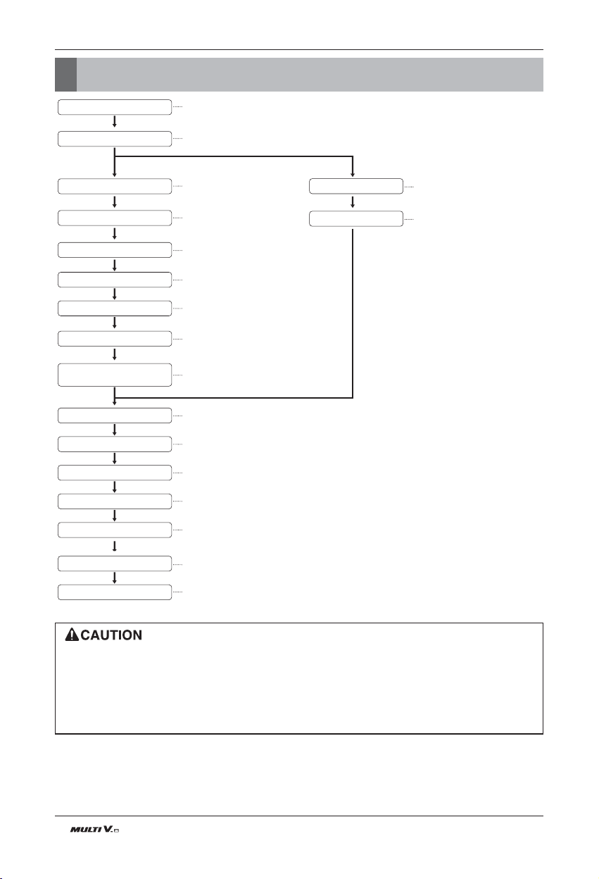
Installation Process
The foundation must be level even
Outdoor unit foundation work
Avoid short circuits and ensure
sufficient space is allowed for service
Installation of outdoor unit
Refer to automatic addressing flowchart
Automatic addressing of indoor unit
In the final check for 24hours at 3.8MPa(551psi) there must be no drop in pressure.
Airtight test
Multiple core cable must not be used.
(suitable cable should be selected)
Electrical work
(connection circuits and drive circuits)
Make sure no gaps are left where
the insulating materials are joined
Heat insulation work
Make sure airflow is sufficient
Duct work
Adjust to downward gradient
Drain pipe work
Special attention to dryness,
cleanness and tightness
Refrigerant piping work
Check model name to make
sure the fitting is made correctly
Installation of indoor unit
Take account of gradient
of drain piping
Sleeve and insert work
Make connection clearly between outdoor, indoor, remote controller and option.
Preparation of contract drawings
Indicate clearly who will be responsible for switch setting.
Determination of division work
The vacuum pump used must have a capacity of reaching at least 5 torr, more than 1 hour
Vacuum drying
Recharge correctly as calculated in this manual. and record the amount of added refrigerant
Additional charge of refrigerant
Make sure there are no gaps left between the facing materials used on the ceiling
Fit facing panels
Run each indoor unit in turn to make sure the pipe work has been fitted correctly
Test run adjustment
Explain the use of the system as clearly as possible to your customer and make sure all relevant
documentation is in order
Transfer to customer with explanation
Preheat the crank case with the electrical heater for more than 6 hours.
• The above list indicates the order in which the individual work operations are normally carried out but this order may be
varied where local conditions warrants such change.
• The wall thickness of the piping should comply with the relevant local and national regulations for the designed pressure
3.8MPa(551psi).
• Since R410A is a mixed refrigerant, the required additional refrigerant must be charged in its liquid state.(If the refriger-
ant is charged in its gaseous state, its composition changes and the system will not work properly.)
8 Outdoor Unit
Installation Process
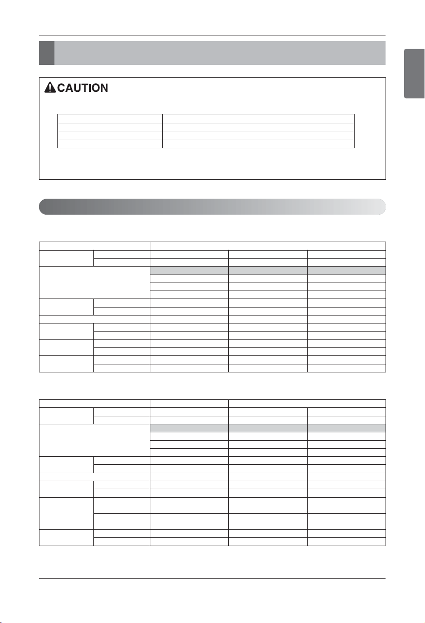
Outdoor units Information
ENGLISH
Installation Manual 9
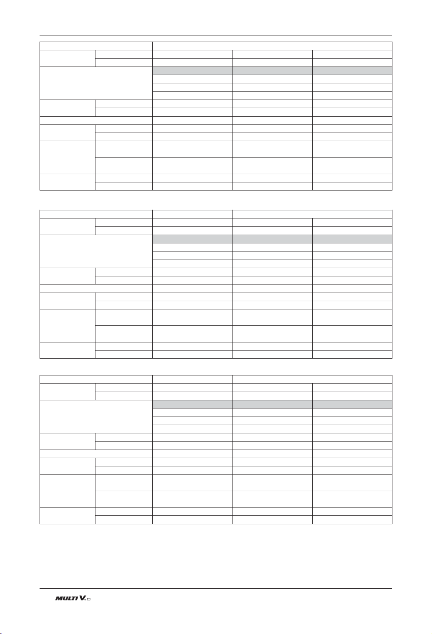
Unit 1 Outdoor Unit 2 Outdoor Unit
System
HP
Ton
Model
Product Charge
kg
lbs
Max. Connectable No. of Indoor Units
Net Weight
kg
lbs
Dimensions
(WxHxD)
mm
inch
Connecting
Pipes
Liquid Pipes[mm(inch)]
Gas Pipes[mm(inch)]
14 18 20
12 14 16
ARUN144BT3 ARUN168BT3 ARUN192BT3
ARUN144BT3 ARUN072BT3 ARUN072BT3
ARUN096BT3 ARUN121BT3
9.4 14.9 14.9
20.7 32.8 32.8
23 26 29
280 × 1 (190 × 1) + (280 × 1) (190 × 1) + (280 × 1)
617 × 1 (418 × 1) + (617 × 1) (418 × 1) + (617 × 1)
(1,240×1,680×760)×1 (920×1,680×760)×1 (920×1,680×760)×1
(1,240×1,680×760)×1 (1,240×1,680×760)×1
(48.8×66.1×29.9)×1 (36.2×66.1×29.9)×1 (36.2×66.1×29.9)×1
(48.8×66.1×29.9)×1 (48.8×66.1×29.9)×1
12.7(1/2) 15.88(5/8) 15.88(5/8)
28.58(1 1/8) 28.58(1 1/8) 28.58(1 1/8)
Outdoor units Information
n Heat pump
n Combination Ration(50~130%)
Notes: * We can guarantee the operation only within 130% Combination.
Outdoor Number Connection Capacity
Single outdoor unit 130%
Double outdoor units 130%
Triple outdoor units 130%
Power Supply: Outdoor Unit (3Ø, 208/230V, 60Hz)
Unit 1 Outdoor Unit
System
HP 81012
Ton 6810
Model
ARUN072BT3 ARUN096BT3 ARUN121BT3
ARUN072BT3 ARUN096BT3 ARUN121BT3
Product Charge
kg 5.5 9.4 9.4
lbs 12.1 20.7 20.7
Max. Connectable No. of Indoor Units
13 16 20
Net Weight
kg 190 x 1 280 × 1 280 × 1
lbs 418 x 1 617 × 1 617 × 1
Dimensions
(WxHxD)
mm (920×1,680×760)×1 (1,240×1,680×760)×1 (1,240×1,680×760)×1
inch (36.2×66.1×29.9)×1 (48.8×66.1×29.9)×1 (48.8×66.1×29.9)×1
Connecting
Pipes
Liquid Pipes[mm(inch)]
9.52(3/8) 9.52(3/8) 12.7(1/2)
Gas Pipes[mm(inch)]
19.05(3/4) 22.2(7/8) 28.58(1 1/8)
Unit 2 Outdoor Unit
System
HP
Ton
Model
Product Charge
kg
lbs
Max. Connectable No. of Indoor Units
Net Weight
kg
lbs
Dimensions
(WxHxD)
mm
inch
Connecting
Pipes
Liquid Pipes[mm(inch)]
Gas Pipes[mm(inch)]
22 24 26
18 20 22
ARUN216BT3 ARUN240BT3 ARUN264BT3
ARUN072BT3 ARUN096BT3 ARUN121BT3
ARUN144BT3 ARUN144BT3 ARUN144BT3
14.9 19 19
32.8 41 41
32 35 39
(190 × 1) + (280 × 1) 280 × 2 280 × 2
(418 × 1) + (617 × 1) 617 × 2 617 × 2
(920×1,680×760)×1 (1,240×1,680×760)×2 (1,240×1,680×760)×2
(1,240×1,680×760)×1
(36.2×66.1×29.9)×1 (48.8×66.1×29.9)×2 (48.8×66.1×29.9)×2
(48.8×66.1×29.9)×1
15.88(5/8) 15.88(5/8) 19.05(3/4)
28.58(1 1/8) 34.9(1 3/8) 34.9(1 3/8)
Unit 2 Outdoor Unit 3 Outdoor Unit
System
HP
Ton
Model
Product Charge
kg
lbs
Max. Connectable No. of Indoor Units
Net Weight
kg
lbs
Dimensions
(WxHxD)
mm
inch
Connecting
Pipes
Liquid Pipes[mm(inch)]
Gas Pipes[mm(inch)]
28 32 34
24 26 28
ARUN288BT3 ARUN312BT3 ARUN336BT3
ARUN144BT3 ARUN072BT3 ARUN072BT3
ARUN144BT3 ARUN096BT3 ARUN121BT3
ARUN144BT3 ARUN144BT3
19 24.3 24.3
41 53.5 53.5
42 45 49
280 × 2 (190 × 1) + (280 × 2) (190 × 1) + (280 × 2)
617 × 2 (418 × 1) + (617 × 2) (418 × 1) + (617 × 2)
(1,240×1,680×760)×2 (920×1,680×760)×1 (920×1,680×760)×1
(1,240×1,680×760)×2 (1,240×1,680×760)×2
(48.8×66.1×29.9)×2 (36.2×66.1×29.9)×1 (36.2×66.1×29.9)×1
(48.8×66.1×29.9)×2 (48.8×66.1×29.9)×2
19.05(3/4) 19.05(3/4) 19.05(3/4)
34.9(1 3/8) 34.9(1 3/8) 34.9(1 3/8)
Unit 1 Outdoor Unit 2 Outdoor Unit
System
HP
Ton
Model
Product Charge
kg
lbs
Max. Connectable No. of Indoor Units
Net Weight
kg
lbs
Dimensions
(WxHxD)
mm
inch
Connecting
Pipes
Liquid Pipes[mm(inch)]
Gas Pipes[mm(inch)]
36 38 40
30 32 34
ARUN360BT3 ARUN384BT3 ARUN408BT3
ARUN072BT3 ARUN096BT3 ARUN121BT3
ARUN144BT3 ARUN144BT3 ARUN144BT3
ARUN144BT3 ARUN144BT3 ARUN144BT3
24.3 28.2 28.2
53.5 62.1 62.1
52 55 58
(190 × 1) + (280 × 2) 280 × 3 280 × 3
(418 × 1) + (617 × 2) 617 × 3 617 × 3
(920×1,680×760)×1 (1,240×1,680×760)×3 (1,240×1,680×760)×3
(1,240×1,680×760)×2
(36.2×66.1×29.9)×1 (48.8×66.1×29.9)×3 (48.8×66.1×29.9)×3
(48.8×66.1×29.9)×2
19.05(3/4) 19.05(3/4) 19.05(3/4)
41.3(1 5/8) 41.3(1 5/8) 41.3(1 5/8)
Outdoor units Information
10 Outdoor Unit
Outdoor Units Information
ENGLISH
Installation Manual 11
Unit 3 Outdoor Unit
System
HP
Ton
Model
Product Charge
kg
lbs
Max. Connectable No. of Indoor Units
Net Weight
kg
lbs
Dimensions
(WxHxD)
mm
inch
Connecting
Pipes
Liquid Pipes[mm(inch)]
Gas Pipes[mm(inch)]
42
36
ARUN432BT3
ARUN144BT3
ARUN144BT3
ARUN144BT3
28.2
62.1
61
280 × 3
617 × 3
(1,240×1,680×760)×3
(48.8×66.1×29.9)×3
19.05(3/4)
41.3(1 5/8)
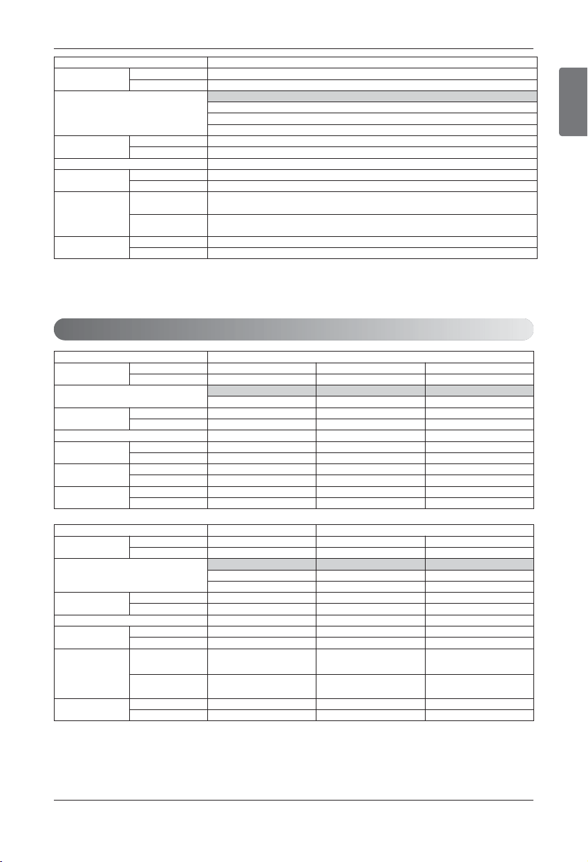
Power Supply: Outdoor Unit (3Ø, 460V, 60Hz)
Unit 1 Outdoor Unit
System
HP
Ton
Model
Product Charge
kg
lbs
Max. Connectable No. of Indoor Units
Net Weight
kg
lbs
Dimensions
(WxHxD)
mm
inch
Connecting
Pipes
Liquid Pipes[mm(inch)]
Gas Pipes[mm(inch)]
81012
6810
ARUN072DT3 ARUN096DT3 ARUN120DT3
ARUN072DT3 ARUN096DT3 ARUN120DT3
5.5 9.4 9.4
12.1 20.7 20.7
13 16 20
190 x 1 270 × 1 270 × 1
418 x 1 595 × 1 595 × 1
(920×1,680×760)×1 (1,240×1,680×760)×1 (1,240×1,680×760)×1
(36.2×66.1×29.9)×1 (48.8×66.1×29.9)×1 (48.8×66.1×29.9)×1
9.52(3/8) 9.52(3/8) 12.7(1/2)
19.05(3/4) 22.2(7/8) 28.58(1 1/8)
Unit 1 Outdoor Unit 2 Outdoor Unit
System
HP 14 18 20
Ton 12 14 16
Model
ARUN144DT3 ARUN168DT3 ARUN192DT3
ARUN144DT3 ARUN072DT3 ARUN072DT3
ARUN096DT3 ARUN120DT3
Product Charge
kg 9.4 14.9 14.9
lbs 20.7 32.8 32.8
Max. Connectable No. of Indoor Units
23 26 29
Net Weight
kg 270 × 1 (190 × 1) + (270 × 1) (190 × 1) + (270 × 1)
lbs 595 × 1 (418 × 1) + (595 × 1) (418 × 1) + (595 × 1)
Dimensions
(WxHxD)
mm (1,240×1,680×760)×1
(920×1,680×760)×1
(1,240×1,680×760)×1
(920×1,680×760)×1
(1,240×1,680×760)×1
inch (48.8×66.1×29.9)×1
(36.2×66.1×29.9)×1
(48.8×66.1×29.9)×1
(36.2×66.1×29.9)×1
(48.8×66.1×29.9)×1
Connecting
Pipes
Liquid Pipes[mm(inch)]
12.7(1/2) 15.88(5/8) 15.88(5/8)
Gas Pipes[mm(inch)]
28.58(1 1/8) 28.58(1 1/8) 28.58(1 1/8)
Outdoor Units Information
12 Outdoor Unit
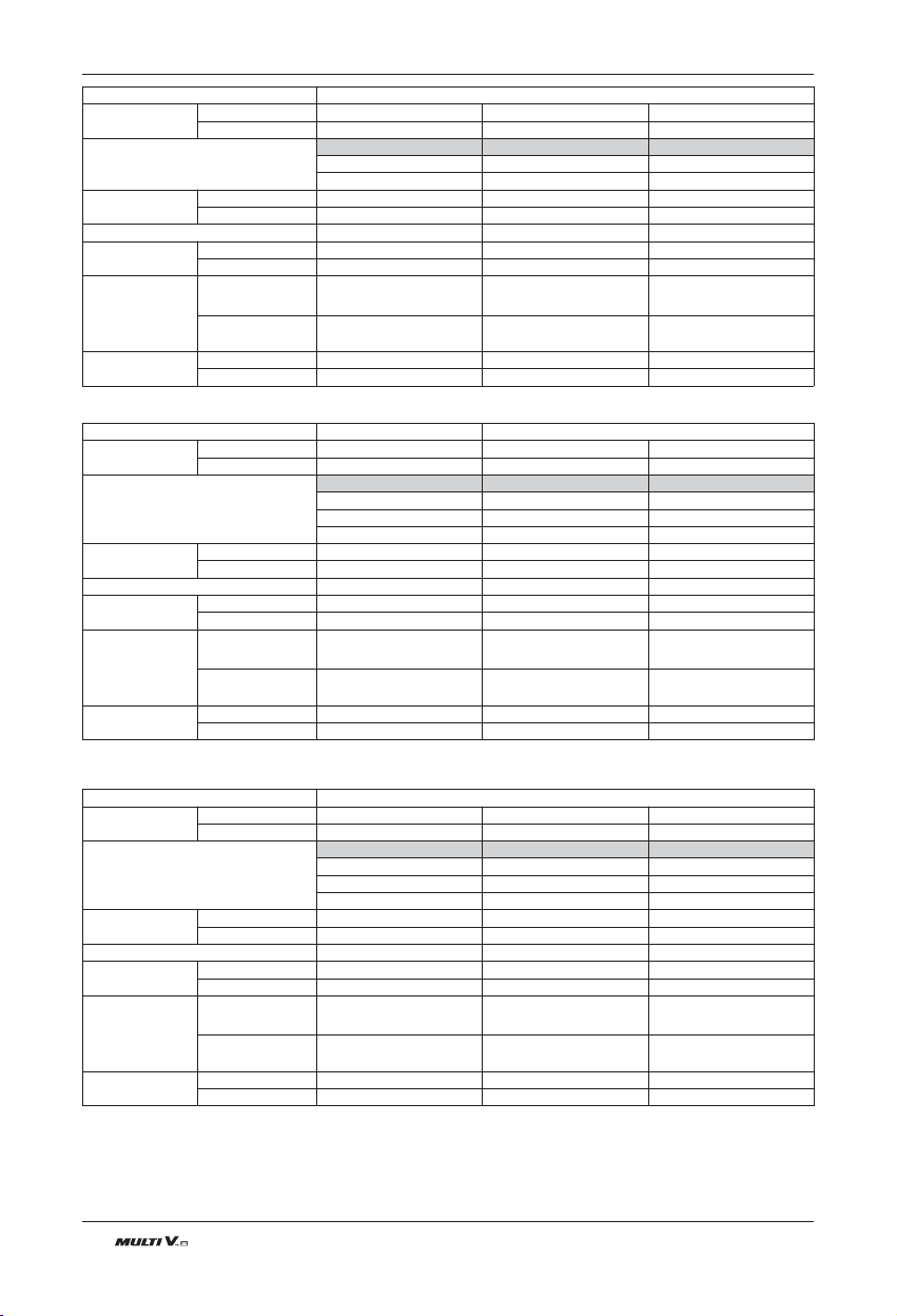
Unit 2 Outdoor Unit
System
HP 22 24 26
Ton 18 20 22
Model
ARUN216DT3 ARUN240DT3 ARUN264DT3
ARUN072DT3 ARUN096DT3 ARUN120DT3
ARUN144DT3 ARUN144DT3 ARUN144DT3
Product Charge
kg 14.9 19 19
lbs 32.8 41 41
Max. Connectable No. of Indoor Units
32 35 39
Net Weight
kg (190 × 1) + (270 × 1) 270 × 2 270 × 2
lbs (418 × 1) + (595 × 1) 595 × 2 595 × 2
Dimensions
(WxHxD)
mm
(920×1,680×760)×1
(1,240×1,680×760)×1
(1,240×1,680×760)×2 (1,240×1,680×760)×2
inch
(36.2×66.1×29.9)×1
(48.8×66.1×29.9)×1
(48.8×66.1×29.9)×2 (48.8×66.1×29.9)×2
Connecting
Pipes
Liquid Pipes[mm(inch)]
15.88(5/8) 15.88(5/8) 19.05(3/4)
Gas Pipes[mm(inch)]
28.58(1 1/8) 34.9(1 3/8) 34.9(1 3/8)
Unit 2 Outdoor Unit 3 Outdoor Unit
System
HP 28 32 34
Ton 24 26 28
Model
ARUN288DT3 ARUN312DT3 ARUN336DT3
ARUN144DT3 ARUN072DT3 ARUN072DT3
ARUN144DT3 ARUN096DT3 ARUN120DT3
ARUN144DT3 ARUN144DT3
Product Charge
kg 19 24.3 24.3
lbs 41 53.5 53.5
Max. Connectable No. of Indoor Units
42 45 49
Net Weight
kg 270 × 2 (190 × 1) + (270 × 2) (190 × 1) + (270 × 2)
lbs 595 × 2 (418 × 1) + (595 × 2) (418 × 1) + (595 × 2)
Dimensions
(WxHxD)
mm (1,240×1,680×760)×2
(920×1,680×760)×1
(1,240×1,680×760)×2
(920×1,680×760)×1
(1,240×1,680×760)×2
inch (48.8×66.1×29.9)×2
(36.2×66.1×29.9)×1
(48.8×66.1×29.9)×2
(36.2×66.1×29.9)×1
(48.8×66.1×29.9)×2
Connecting
Pipes
Liquid Pipes[mm(inch)]
19.05(3/4) 19.05(3/4) 19.05(3/4)
Gas Pipes[mm(inch)]
34.9(1 3/8) 34.9(1 3/8) 34.9(1 3/8)
Unit 3 Outdoor Unit
System
HP 36 38 40
Ton 30 32 34
Model
ARUN360DT3 ARUN384DT3 ARUN408DT3
ARUN072DT3 ARUN096DT3 ARUN120DT3
ARUN144DT3 ARUN144DT3 ARUN144DT3
ARUN144DT3 ARUN144DT3 ARUN144DT3
Product Charge
kg 24.3 28.2 28.2
lbs 53.5 62.1 62.1
Max. Connectable No. of Indoor Units
52 55 58
Net Weight
kg (190 × 1) + (270 × 2) 270 × 3 270 × 3
lbs (418 × 1) + (595 × 2) 595 × 3 595 × 3
Dimensions
(WxHxD)
mm
(920×1,680×760)×1
(1,240×1,680×760)×2
(1,240×1,680×760)×3 (1,240×1,680×760)×3
inch
(36.2×66.1×29.9)×1
(48.8×66.1×29.9)×2
(48.8×66.1×29.9)×3 (48.8×66.1×29.9)×3
Connecting
Pipes
Liquid Pipes[mm(inch)]
19.05(3/4) 19.05(3/4) 19.05(3/4)
Gas Pipes[mm(inch)]
41.3(1 5/8) 41.3(1 5/8) 41.3(1 5/8)
ENGLISH
Outdoor Units Information
Installation Manual 13
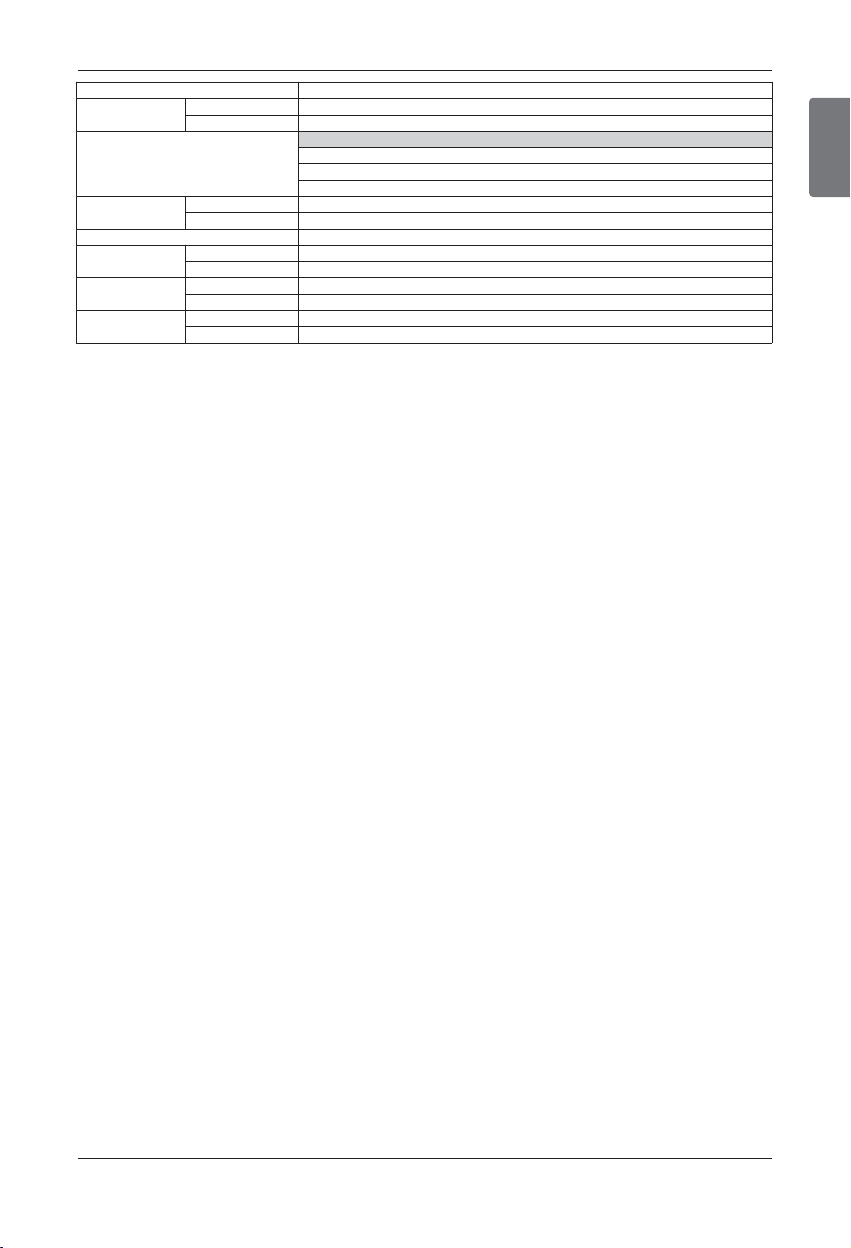
Unit 3 Outdoor Unit
System
HP
Ton
Model
Product Charge
kg
lbs
Max. Connectable No. of Indoor Units
Net Weight
kg
lbs
Dimensions
(WxHxD)
mm
inch
Connecting
Pipes
Liquid Pipes[mm(inch)]
Gas Pipes[mm(inch)]
42
36
ARUN432DT3
ARUN144DT3
ARUN144DT3
ARUN144DT3
28.2
62.1
61
270 × 3
595 × 3
(1,240×1,680×760)×3
(48.8×66.1×29.9)×3
19.05(3/4)
41.3(1 5/8)
14 Outdoor Unit
• The refrigerant R410A has the property of higher operating pressure in comparison with R22.
Therefore, all materials have the characteristics of higher resisting pressure than R22 ones and this character-
istic should be also considered during the installation.
R410A is an azeotrope of R32 and R125 mixed at 50:50, so the ozone depletion potential (ODP) of R410A is
0. These days the developed countries have approved it as the environment-friendly refrigerant and encour-
aged to use it widely to prevent environment pollution.
CAUTION:
• The wall thickness of the piping should comply with the relevant local and national regulations for the designed
pressure 3.8MPa(551.1psi).
• Since R410A is a mixed refrigerant, the required additional refrigerant must be charged in its liquid state.
If the refrigerant is charged in its gaseous state, its composition changes and the system will not work properly.
• Do not place the refrigerant container under the direct rays of the sun to prevent it from exploding.
• For high-pressure refrigerant, any unapproved pipe must not be used.
• Do not heat pipes more than necessary to prevent them from softening.
• Be careful not to install wrongly to minimize economic loss because it is expensive in comparison with R22.
Environment-friendly Alternative Refrigerant R410A
Environment-friendly Alternative Refrigerant R410A

ENGLISH
Installation Manual 15
Select the Best Location
Select the Best Location
Select space for installing outdoor unit, which will meet the following conditions:
• No direct thermal radiation from other heat sources
• No possibility of annoying neighbors by noise from unit
• No exposition to strong wind
• With strength which bears weight of unit
• Note that drain flows out of unit when heating
• With space for air passage and service work shown next
• Because of the possibility of fire, do not install unit to the space where generation, inflow, stagnation, and
leakage of combustible gas is expected.
• Avoid unit installation in a place where acidic solution and spray (sulfur) are often used.
• Do not use unit under any special environment where oil, steam and sulfuric gas exist.
• It is recommended to fence round the outdoor unit in order to prevent any person or animal from accessing the
outdoor unit.
• If installation site is area of heavy snowfall, then the following directions should be observed.
- Make the foundation as high as possible.
- Fit a snow protection hood.
• Select installation location considering following conditions to avoid bad condition when additionally performing
defrost operation.
1. Install the outdoor unit at a place well ventilated and having a lot of sunshine in case of installing the prod-
uct at a place With a high humidity in winter (near beach, coast, lake, etc. )
(Ex : Rooftop where there is always sunshine.)
16 Outdoor Unit
Installation Space
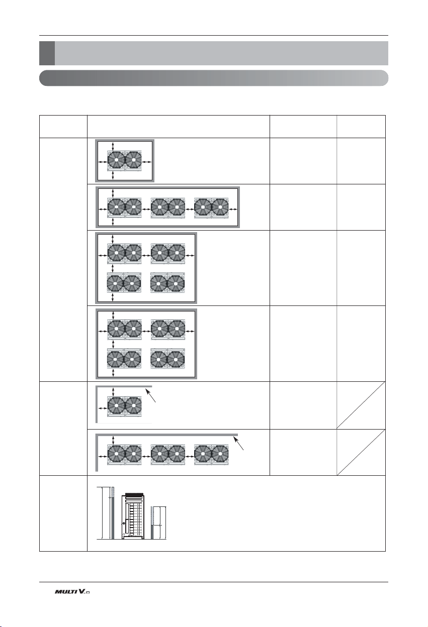
Installation Space
Individual Installation
n During the installation of the unit, consider service, inlet, and outlet and acquire the minimum space
as shown in the figures below.
A E
B
D
A
C
B
D
E
C
A E
B
F
C
D
A E
B
F
C
D
A
E
B
A
B
E
Q
R
a
b
QYMQQOQV@
UYMQOQV@
Category
Case 1
(10mm≤Space A, C≤49mm)
Case 2
(Space A, C
≥
49mm)
Installation Space
4 sides are
walls
Only 2 sides
are walls
Limitations on
the height of
the wall
(Refer to 4 side
walls)
Front
Front
Front
Front
Front
Front
Front
No limit to the height of the wall
No limit to the
height of the wall
Front
• The height of the wall on the front side must be 1500mm(59-1/16 inch) or less.
• The height of the wall on the inlet side must be 500mm(19-11/16 inch) or less.
• There is no limit to the wall on the side.
• If the height of the walls on the front and the inlet are higher than the limit, there
must be additional space on the front and the side.
- Additional Space on the inlet side by 1/2 of h1.
- Additional Space on the front side by 1/2 of h2
- h2 = A(Actual height) - 59-1/16
- h1 = B(Actual height) - 19-11/16
A≥10(13/32”) A≥50(1-31/32”)
B≥300(11-13/16”) B≥100(3-15/16”)
C≥10(13/32”) C≥50(1-31/32”)
D≥500(19-11/16”) D≥500(19-11/16”)
A≥10(13/32”) A≥50(1-31/32”)
B≥300(11-13/16”) B≥100(3-15/16”)
C≥10(13/32”) C≥50(1-31/32”)
D≥500(19-11/16”) D≥500(19-11/16”)
E≥20(25/32”) E≥100(3-15/16”)
A≥10(13/32”) A≥50(1-31/32”)
B≥300(11-13/16”) B≥100(3-15/16”)
C≥10(13/32”) C≥50(1-31/32”)
D≥500(19-11/16”) D≥500(19-11/16”)
E≥20(25/32”) E≥100(3-15/16”)
F≥600(23-5/8”) F≥500(19-11/16”)
A≥10(13/32”) A≥50(1-31/32”)
B≥300(11-13/16”) B≥100(3-15/16”)
C≥10(13/32”) C≥50(1-31/32”)
D≥300(11-13/16”) D≥100(3-15/16”)
E≥20(25/32”) E≥100(3-15/16”)
F
≥500(19-11/16”) F≥500(19-11/16”)
A≥10(13/32”)
B≥300(11-13/16”)
A≥200(7-7/8”)
B≥300(11-13/16”)
E≥400(15-3/4”)

ENGLISH
Installation Manual 17
Installation Space
Seasonal wind and cautions in winter
• Sufficient measures are required in a snow area or severe cold area in winter so that product can be operated well.
• Get ready for seasonal wind or snow in winter even in other areas.
• Install a suction and discharge duct not to let in snow or rain.
• Install the outdoor unit not to come in contact with snow directly. If snow piles up and freezes on the air suction
hole, the system may malfunction. If it is installed at snowy area, attach the hood to the system.
• Install the outdoor unit at the higher installation console by 500mm(19-11/16inch) inch than the average snowfall
(annual average snowfall) if it is installed at the area with much snowfall.
• Where snow accumulated on the upper part of the Outdoor Unit by more than 100mm(3-15/16inch), always remove
snow for operation.
1. The height of H frame must be more than 2 times the snowfall and its width shall not exceed the width of the
product. (If width of the frame is wider than that of the product, snow may accumulate)
2. Don't install the suction hole and discharge hole of the Outdoor Unit facing the seasonal wind.
18 Outdoor Unit
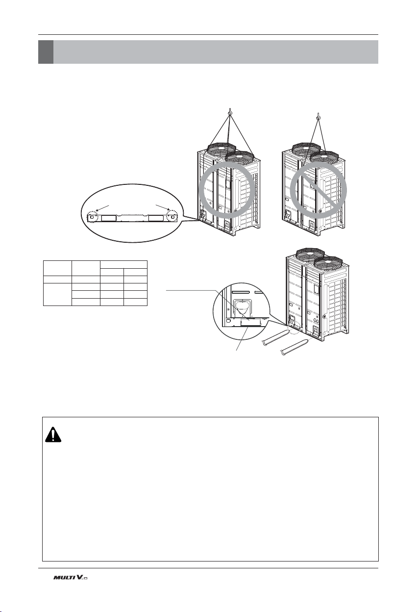
Lifting Method
• When carrying the suspended, unit pass the ropes under the unit and use the two suspension points each at the
front and rear.
• Always lift the unit with ropes attached at four points so that impact is not applied to the unit.
• Attach the ropes to the unit at an angle of 40° or less.
Lifting method
CAUTION
Be very careful while carrying the product.
• Do not have only one person carry product if it is more than 20kg(44lbs).
• PP bands are used to pack some products. Do not use them as a mean for transportation because they
are dangerous.
• Do not touch heat exchanger fins with your bare hands. Otherwise you may get a cut in your hands.
• Tear plastic packaging bag and scrap it so that children cannot play with it. Otherwise plastic packaging
bag may suffocate children to death.
• When carrying in Outdoor Unit, be sure to support it at four points. Carrying in and lifting with 3-point
support may make Outdoor Unit unstable, resulting in a fall.
• Use 2 belts of at least 3m(26.2ft) long.
• Place extra cloth or boards in the locations where the casing comes in contact with the sling to prevent
damage.
• Hoist the unit making sure it is being lifted at its center of gravity.
Weight per Capacity
Locking points for
transportation ropes
Forklift Carrying Guide
Forklift Carrying Hole
Chassis
Capacity
[HP(Ton)]
Weight [kg(lbs)]
3Ø 208/230V
3Ø 460V
UX2 8 (6) 190 (418) 190 (418)
UX3
10 (8) 280 (617) 270 (595)
12 (10) 280 (617) 270 (595)
14 (12) 280 (617) 270 (595)
ENGLISH
Installation Manual 19
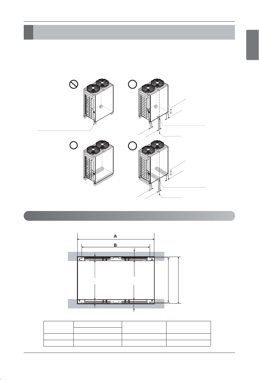
Installation
Installation
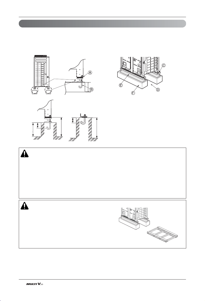
The location of the Anchor bolts
• Install at places where it can endure the weight and vibration/noise of the outdoor unit.
• The outdoor unit supports at the bottom shall have width of at least 100mm(3-15/16 inch) under the units legs before
being fixed.
• The outdoor unit supports should have minimum height of 200mm(7-7/8 inch).
• Anchor bolts (M10) must be inserted at least 75mm(2-15/16 inch).
At least 100mm
At least 100mm
At lea
s
t 100mm
At least 100mm
At least 100mm
Set up supports under center of the unit.
Center of the Unit
At least 100mm
At least 200mm
The outdoor unit should not be
supported only by the corner
supports.
Set up supports under center of the unit.
Center of the Unit
At least 200mm
730(28-3/4)
760(29-29/32)
65(2-9/16)
65(2-9/16)
Unit : mm(inch)
At least
65(2-9/16)
At least
65(2-9/16)
Chassis
Outdoor unit capacity
A [mm(inch)] B [mm(inch)]
H/R
UX2 8HP 920(36-7/32) 792(31-3/16)
UX3 10~14HP 1240(48-13/16) 1102(43-3/8)
20 Outdoor Unit
Installation
Foundation for Installation
• Fix the unit tightly with bolts as shown below so that unit will not fall down due to earthquake or gust.
• Use the H-beam support as a base support
• Noise and vibration may occur from the floor or wall since vibration is transferred through the installation part
depending on installation status. Thus, use anti-vibration materials (cushion pad) fully (The base pad shall
be more than 200mm(7-7/8 inch).
At least 200mm
(7-7/8 inch)
At least 10mm
(13/32 inch)
Unit : mm(inch)
75(2-15/16)
75(2-15/16)
100(3-15/16)
200(7-7/8)
200(7-7/8)
Ⓐ The corner part must be fixed firmly. Otherwise, the
support for the installation may be bent.
Ⓑ Get and use M10 Anchor bolt.
Ⓒ Put Cushion Pad between the outdoor unit and ground
support for the vibration protection in wide area.
Ⓓ Space for pipes and wiring (Pipes and wirings for bottom
side)
Ⓔ H-beam support
Ⓕ Concrete support
WARNING
• Install where it can sufficiently support the weight of the outdoor unit.
If the support strength is not enough, the outdoor unit may drop and hurt people.
• Install where the outdoor unit may not fall in strong wind or earthquake.
If there is a fault in the supporting conditions, the outdoor unit may fall and hurt people.
• Please take extra cautions on the supporting strength of the ground, liquid outlet
treatment(treatment of the liquid flowing out of the outdoor unit in operation), and the passages of
the pipe and wiring, when making the ground support.
• Do not use tube or pipe for liquid outlet in the Base pan. Use drainage instead for liquid outlet.
The tube or pipe may freeze and the liquid may not be drained.
WARNING
• Be sure to remove the MDF(wood support) of the bottom
side of the outdoor unit Base Pan before fixing the bolt.
It may cause the unstable state of the outdoor
settlement, and may cause freezing of the heat
exchanger resulting in abnormal operations.
• Be sure to remove the MDF(wood support) of the bottom
side of the outdoor unit before welding. Not removing
MDF causes hazard of fire during welding.
Pallet(Wood Support)
- Remove before Installation
<5.6(19,100) 1/2 1/4
0.02~0.03 0~0.02
(0.5~0.8) (0~0.5)
<16.0(54,600) 5/8 3/8
0.03~0.04 0.02~0.03
(0.8~1.0) (0.5~0.8)
<22.4(76,400) 3/4 3/8
0.04~0.05 0.02~0.03
(1.0~1.3) (0.5~0.8)
ENGLISH
Installation Manual 21
Installation
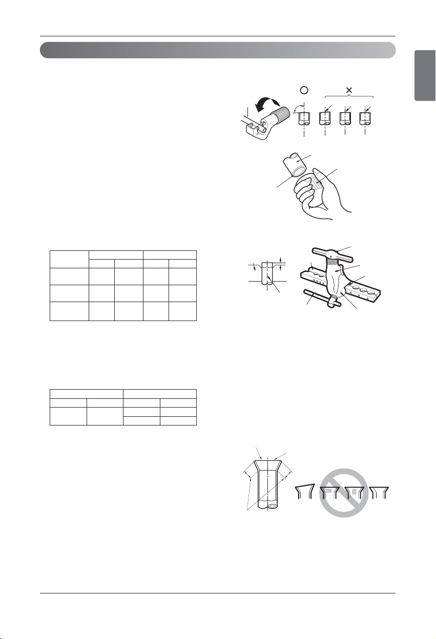
Preparation of Piping
1) Cut the pipes and the cable.
n Use the accessory piping kit or the pipes purchased lo-
cally.
n Measure the distance between the indoor and the out-
door unit.
n Cut the pipes a little longer than measured distance.
2) Burrs removal
n Completely remove all burrs from the cut cross section
of pipe/tube.
n Put the end of the copper tube/pipe to downward direc-
tion as you remove burrs in order to avoid to let burrs
drop in the tubing.
3) Flaring work
n Carry out flaring work using flaring tool as shown below.
n For below models, carry out flaring work using flaring
tool as shown below.
Applicable Indoor unit models:
ARNU093TN★2, ARNU123TN★2, ARNU153TN★2,
ARNU183TM★2, ARNU243TM★2, ARNU153BG★2,
ARNU183BG★2, ARNU243BG★2
n
Firmly hold copper tube in a bar (or die) as indicated di-
mension in the table above.
4) Check
n Compare the flared work with figure below.
n If flare is noted to be defective, cut off the flared section
and do flaring work again.
Main cause of gas leakage is defect in flaring work. Carry out correct flaring work in the following procedure.
Pipe [inch]
“ A “ [inch]
Gas Liquid Gas
Liquid
Indoor unit
[kW(Btu/h]
Copper
tube
90
Slanted Uneven Rough
Pipe
Reamer
Point down
Bar
Copper pipe
Clamp handle
Red arrow mark
Cone
Yoke
Handle
Bar
"A"
Inclined
Inside is shining without scratches.
Smooth all round
Even length
all round
Surface
damaged
Cracked Uneven
thickness
= Improper flaring =
Pipe [inch] “A” [inch(mm)]
Gas Liquid Gas Liquid
5/8 3/8
0.03~0.04 0.02~0.03
(0.8~1.0) (0.5~0.8)
22 Outdoor Unit
Installation
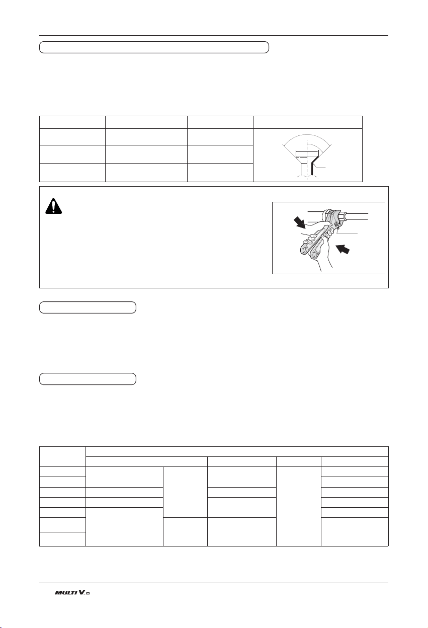
Precautions when connecting pipes
• See the following table for flare part machining dimensions.
• When connecting the flare nuts, apply refrigerant oil to the inside and outside of the flares and turn them three
or four times at first. (Use ester oil or ether oil.)
• See the following table for tightening torque.(Applying too much torque may cause the flares to crack.)
• After all the piping has been connected, use nitrogen to perform a gas leak check.
Union
CAUTION
• Always use a charge hose for service port connection.
•
After tightening the cap, check that no refrigerant leaks are present.
• When loosening a flare nut, always use two wrenches in
combination, When connecting the piping, always use a spanner
and torque wrench in combination to tighten the flare nut.
• When connecting a flare nut, coat the flare(inner and outer faces)
with oil for R410A(PVE) and hand tighten the nut 3 to 4 turns as
the initial tightening.
FLARE SHAPE and FLARE NUT TIGHTENING TORQUE
90
2
45
2
A
R=0.4(1/64)~0.8(1/32)
Pipe size [inch(mm)]
Tightening torque [lbf-in(Ncm)]
A [inch(mm)] flare shape
Ø3/8(9.52) 289.4(3270)-353.1(3990) 0.5(12.8)-0.52(13.2)
Ø1/2(12.7) 438.1(4950)-533.7(6030) 0.64(16.2)-0.65(16.6)
Ø5/8(15.88) 547.0(6180)-667.3(7540) 0.76(19.3)-0.78(19.7)
1. Remove the cap and turn the valve counter clockwise with the hexagon wrench.
2. Turn it until the shaft stops.
Do not apply excessive force to the shutoff valve. Doing so may break the valve body, as the valve is not a
backseat type. Always use the special tool.
3. Make sure to tighten the cap securely.
1. Remove the cap and turn the valve clockwise with the hexagon wrench.
2. Securely tighten the valve until the shaft contacts the main body seal.
3. Make sure to tighten the cap securely.
* For the tightening torque, refer to the table on the below.
Tightening torque
Opening shutoff valve
Closing shutoff valve
Shutoff valve
size
Tightening torque(Turn clockwise to close) [N·m(lbf·ft)]
Shaft(valve body) Cap(Valve lid) Service port Flare nut
Ø6.35(1/4)
5.4(4.0) ~ 6.6(4.9)
Hexagonal
wrench
4mm
(5/8inch)
13.5(10.0) ~
16.5(12.2)
11.5(8.5)
~ 13.9(10.3)
14(10.3) ~ 17(12.5)
Ø9.52(3/8) 33(24.3) ~ 39(28.8)
Ø12.7(1/2) 8.1(6.0) ~ 9.9(7.3) 18(13.3) ~ 22(16.2) 50(36.9) ~ 60(44.3)
Ø15.88(5/8) 13.5(10.0) ~ 16.5(12.2)
23(17.0) ~ 27(19.9)
62(45.7) ~ 75(55.3)
Ø19.05(3/4)
27(19.9) ~ 33(24.3)
93(68.6) ~119(87.8)
Ø22.2(7/8)
Hexagonal
wrench
8mm(5/16inch)
36(26.6) ~ 44(32.5) -
Ø28(1
1
/
8
)

ENGLISH
Installation Manual 23
1. Use the heat insulation material for the refrigerant piping which has an excellent heat-resistance
(over 248℉(120℃)).
2. Precautions in high humidity circumstance:
This air conditioner has been tested according to the
"ISO Conditions with Mist" and confirmed that there is
not any default. However, if it is operated for a long
time in high humid atmosphere (dew point tempera-
ture: more than 73℉(23℃)), water drops are liable to
fall. In this case, add heat insulation material accord-
ing to the following procedure:
• EPDM (Ethylene Propylene Diene Methylene), NBR
(Nitrile Butadiene Rubber) – over 248℉(120℃)
the heat-resistance temperature.
• Add the insulation over 10mm (13/32inch) thickness at high humidity environment.
Indoor unit
Thermal insulator
(accessory)
Fastening band
(accessory)
Refrigerant piping
HEAT INSULATION
Installation
24 Outdoor Unit
Precautions on Pipe connection / Valve operation
Refrigerant piping installation
Refrigerant piping installation
1. For High Low Pressure Common Pipe, use provided elbows to
connect between the outdoor units using pipes.
2. During the cutting of the pipes, remove burr, foreign substances
before connecting. Otherwise, the unit may not operate because
of the sludge inside the pipe.
3. Apply Nitrogen Gas of pressure until 551.1psi(38.7kgf/cm²) for
work area leakage test.
4. After the degree of a vacuum reaches 0.097psi(5torr), continue the
vacuuming work for more than 1 hour.
5. Open the side pole with hexagonal wrench.
Installing 2 units
Installing 3 units
Gas pipe
Liquid pipe
Common pipe
Pipe connection is done by connecting from the end of the pipe to the
branching pipes, and the refrigerant pipe coming out of the outdoor
unit is divided at the end to connect to each indoor unit. Flare connec-
tion for the indoor unit, and welding connection for the outdoor pipe
and the branching parts.
• Use hexagonal wrench to open/close the valve.
h When connecting to high low pressure com-
mon pipe, connect pipes using connecting
elbows.
Detach knock outs according
the usages.
Detach
knock outs
according
the usages.
Installing on the front side Installing on the side(Limited to high
low pressure common pipe)
WARNING
• Always careful not to leak the refrigerant during welding.
• The refrigerant generates poisonous gas harmful to human body if combusted.
• Do not perform welding in a closed space.
• Be sure to close the cap of the service port to prevent gas leakage after the work.
CAUTION
Please block the pipe knock outs of the front and side panels after installing the pipes.
(Animals or foreign objects may be brought in to damage the cables.)
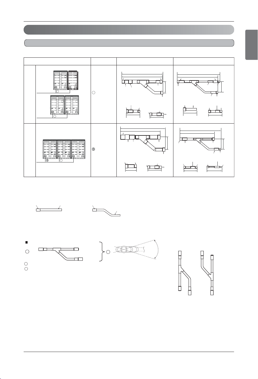
High Low Pressure Common Pipe Connections
ENGLISH
Installation Manual 25
Refrigerant piping installation
2 outdoor units
Connection of Outdoor units
2 Unit
3 Unit
ARCNN21
ARCNN31
C
C
C
C
130(5-1/8)
416(16-3/8)
331(13-1/32)
314(12-3/8)
408(16-1/16)
111(4-3/8)
I.D.38.1(1-1/2)
I.D.34.9(1-3/8)
I.D.34.9(1-3/8)
O.D.34.9(1-3/8)
O.D.19.05(3/4)
O.D.15.88(5/8)
O.D.19.05(3/4)
O.D.19.05(3/4)
O.D.34.9(1-3/8)
125(4-29/32)
406(15-31/32)
353(13-29/32)
111(4-3/8)
I.D.41.3(1-5/8)
I.D.41.3(1-5/8)
I.D.31.8(1-1/4)
I.D.28.58(1-1/8)
I.D.19.05(3/4)
I.D.15.88(5/8)
I.D.15.88(5/8)
I.D.15.88(5/8)
I.D.15.88(5/8)
I.D.28.58(1-1/8)
I.D.28.58(1-1/8)
I.D.28.58(1-1/8)
I.D.22.2(7/8)
I.D.22.2(7/8)
110(4-11/32)
120(4-23/32)
120(4-23/32)
I.D.22.2(7/8)
I.D.12.7(1/2)
I.D.12.7(1/2)
I.D.12.7(1/2)
I.D.12.7(1/2)
I.D.9.52(3/8)
I.D.41.3(1-5/8)
70(2-3/4)
83(3-9/32)
334(13-5/32)
281(11-1/16)
83(3-9/32)
Outdoor units Model Gas pipe Liquid pipe
I.D.
9.52(3/8)
O.D. 19.05(3/4)
I.D. 15.88(5/8)
O.D. 12.7(1/2)
I.D. 12.7(1/2)
I.D. 6.35(1/4)
X2
110(4-11/32)
110(4-11/32)
I.D.9.52(3/8)
I.D.22.2(7/8)
I.D.19.05(3/4)
O.D.28.58(1-1/8)
I.D.22.2(7/8)
I.D.19.05(3/4)
O.D.28.58(1-1/8)
I.D34.9(1-3/8)
I.D38.1(1-1/2)
I.D.3/4(19.05)
O.D.3/4(19.05)
I.D.3/4(19.05)
O.D.3/4(19.05)
For more information, refer accessory installation manual.
Field Supply (Not provided by LG)
Common pipes
[Unit: inch(mm)]
Y branch
A
B
To outdoor unit
To branch piping or indoor unit
A
B
Facing
upwards
Facing
downwards
Within ± 3° Within ± 3°
Viewed from point A
in direction of arrow
Within +/- 10
26 Outdoor Unit
Refrigerant piping installation
To Outdoor Unit
Sealed Piping
A
A
B
A
B
1. Use the following materials for refrigerant piping.
• Material: Seamless phosphorous deoxidized copper pipe
• Wall thickness :
Comply with the relevant local and national regulations for the designed pressure
3.8Mpa(551.1psi). We recommend the following table as the minimum wall thickness.
2. Commercially available piping often contains dust and other materials. Always blow it clean with a dry inert
gas.
3. Use care to prevent dust, water or other contaminants from entering the piping during installation.
4. Reduce the number of bending portions as much as possible, and make bending radius as big as possible.
5. Always use the branch piping set shown below, which are sold separately.
6. If the diameters of the branch piping of the designated refrigerant piping differs, use a pipe cutter to cut
the connecting section and then use an adapter for connecting different diameters to connect the piping.
7. Always observe the restrictions on the refrigerant piping (such as rated length, difference in height, and
piping diameter).
Failure to do so can result in equipment failure or a decline in heating/cooling performance.
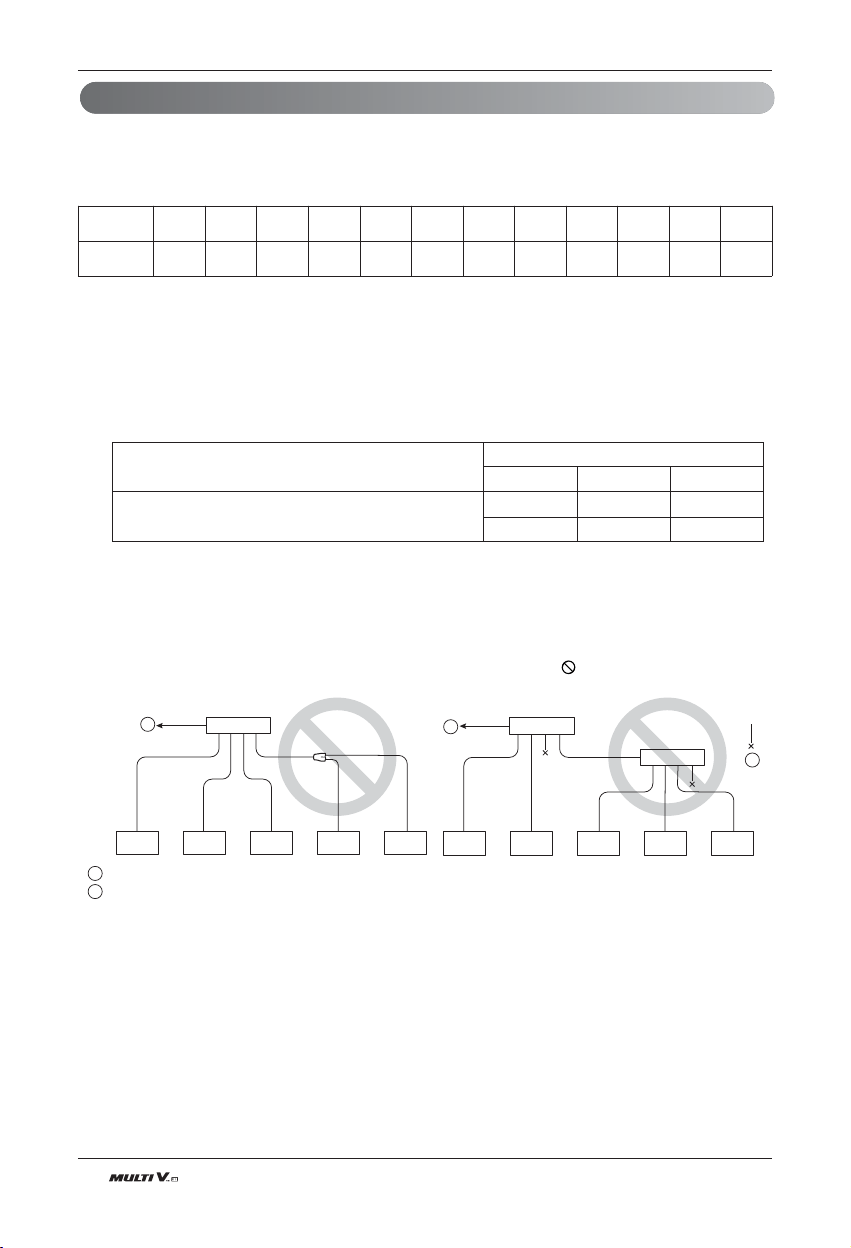
8. A second branch cannot be made after a header. (These are shown by .)
9. The Multi V will stop due to an abnormality like excessive or insufficient refrigerant. At such a time, always
properly charge the unit. When servicing, always check the notes concerning both the piping length and
the amount of additional refrigerant.
10. Never perform a pump down. This will not only damage the compressor but also deteriorate the perform-
ance.
11. Never use refrigerant to perform an air purge. Always evacuate air by using a vacuum pump.
Caution
Outer diameter
[mm(inch
)]
6.35
(1/4)
9.52
(3/8)
12.7
(1/2)
15.88
(5/8)
19.05
(3/4)
22.2
(7/8)
25.4
(1)
28.58
(1-1/8)
31.8
(1-1/4)
34.9
(1-3/8)
38.1
(1-1/2)
41.3
(1-5/8)
Minimum thickness
[mm(inch
)]
0.8
(0.0315)
0.8
(0.0315)
0.8
(0.0315)
0.99
(0.039)
0.99
(0.039)
0.99
(0.039)
0.99
(0.039)
0.99
(0.039)
1.1
(0.043)
1.21
(0.048)
1.35
(0.053)
1.43
(0.056)
ARBL054 ARBL057 ARBL1010
ARBL104 ARBL107 ARBL2010
Y branch
ARBLN01621, ARBLN03321,
ARBLN07121, ARBLN14521
Header
4 branch 7 branch 10 branch
ENGLISH
Installation Manual 27
Refrigerant piping installation
WARNING
When installing and moving the air conditioner to another site, be sure to make recharge refrigerant
after perfect evacuation.
- If a different refrigerant or air is mixed with the original refrigerant, the refrigerant cycle may malfunction and
the unit may be damaged.
- After selecting diameter of the refrigerant pipe to suit total capacity of the indoor unit connected after
branching, use an appropriate branch pipe set according to the pipe diameter of the indoor unit and the in-
stallation pipe drawing.
12. Always insulate the piping properly. Insufficient insulation will result in a decline in heating/cooling per-
formance, drip of condensate and other such problems.
13. When connecting the refrigerant piping, make sure the service valves of the Outdoor Unit is completely
closed (the factory setting) and do not operate it until the refrigerant piping for the Outdoor and Indoor
Units has been connected, a refrigerant leakage test has been performed and the evacuation process
has been completed.
14. Always use a non-oxidizing brazing material for brazing the parts and do not use flux. If not, oxidized film
can cause clogging or damage to the compressor unit and flux can harm the copper piping or refrigerant
oil.
28 Outdoor Unit
Left Side Pipe Draw Out
Front Side Pipe Draw Out
Right Side Pipe Draw Out
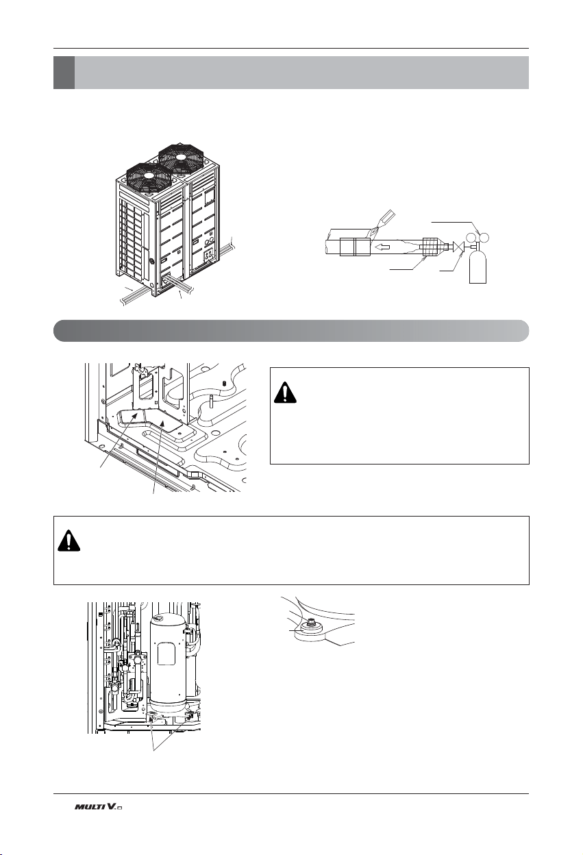
• Pipe connections can be done on the front side or on the side according to the installation environments.
• Be sure to let 2.8psi(0.2kgf/cm²) Nitrogen flow in the pipe when welding.
• If Nitrogen was not flown during welding, many oxidized membranes may form inside the pipe and disturb the normal
operations of valves and condensers.
• Use Knock Outs of Base Pan of the outdoor unit for Left/Right or Bottom pipe drawing outs.
Refrigerant Pipe
Regulator
Nitrogen
Nitrogen
Direction
Taping
Valve
Removal Area for common
pipe bottom side connections.
Removal Area for Liquid/Gas pipe
bottom side connections.
1. Open the front panel.
2. Remove Brackets
3. Fix with only nut and washer as shown in the
figure.
Brackets for Transportation
Washer
Nut
Pipe connections between indoor and outdoor unit
Preparation Work
CAUTION
•
Do not give damage to the pipe/base during the Knock Out work.
•
Proceed to pipe work after removing burr after Knock Out work.
• Perform sleeve work to prevent damage to the wire when
connecting wires using Knock Outs.
CAUTION
• Remove the brackets on the inverter condenser legs that were fixed to protect the unit during the transportation.
(If bracket is not removed, abnormal noise or vibration may occur.)
Pipe connections between indoor and outdoor unit
ENGLISH
Installation Manual 29
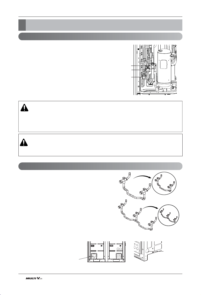
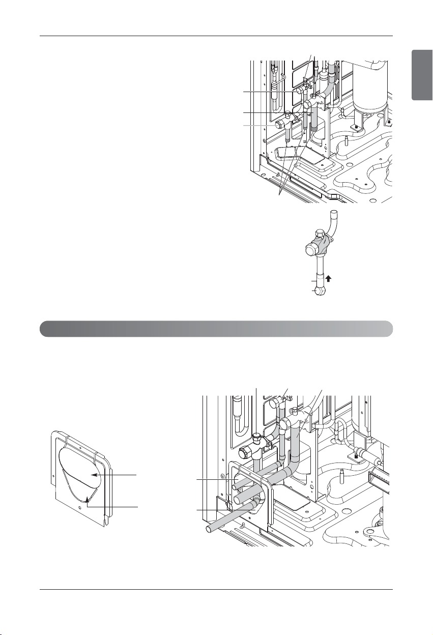
n Remove leakage prevention cap
• Remove the leakage prevention cap attached to the out-
door unit service valve before pipe work.
• Proceed the leakage prevention cap removal as follows:
1. Verify whether the liquid/gas/common pipes are locked.
2. Extract remaining refrigerant or air inside using the
service port.
3. Remove the leakage prevention cap
n Method of pipe cap work during the instal-
lation of single outdoor unit
1. Remove rubber cap inserted in the common pipe.
2. Wrap the common pipe service valve with wet towel.
3. Insert the pipe cap provided into the common pipe.
4. Place high/low pressure flare nut cap under the pipe cap so
that the pipe cap does not move.
5. Weld the pipe cap.
h If not wrapped with a wet towel, there may be damages in-
side the valve.
h If the unit is operated without pipe cap work, there may be
abnormality in the cycle caused by refrigerant leakage.
n Method of drawing out pipes on the front side
• Proceed with the pipe work as shown in the below figure for front side pipe drawing out.
Liquid pipe
Gas pipe
Common pipe
Service Port
Leakage Prevention Cap
Pipe Cap
Flare Nut
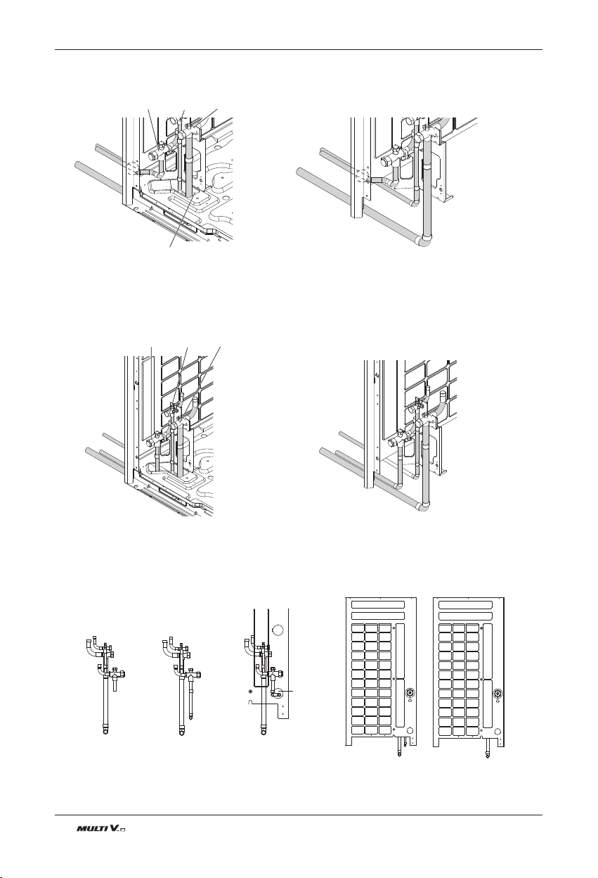
Pipe Drawing Out during Single / Series connection
Common pipe Liquid pipe Gas pipe
Pipe Knock Out for
Liquid/Gas pipes
Pipe Knock Out for
common pipes
Pipe connections between indoor and outdoor unit
30 Outdoor Unit
Common pipe Liquid pipe Gas pipe
Remove only liquid/gas pipe Knock Out View without base pan
Common pipe
View without base pan
Liquid pipe Gas pipe
n Method of drawing out pipes on the bottom side
①
Drawing out common pipe through side panel
n Figure of Sides when drawing out through bottom pipe
②
Drawing out common pipe through bottom pipe
Remove Pipe
Knock Out Hole
i) Single outdoor unit
ii) Series outdoor units
(Draw out common pipes
through bottom)
iii) Series outdoor units
(Draw out common pipes
through side panel)
Pipe connections between indoor and outdoor unit
ENGLISH
Installation Manual 31
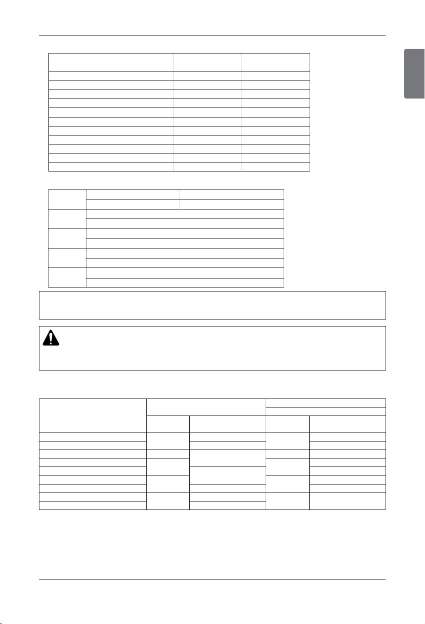
Pipe connections between indoor and outdoor unit
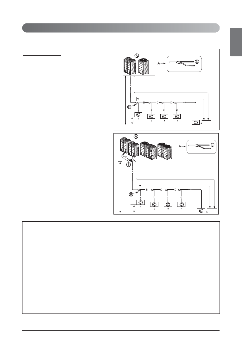
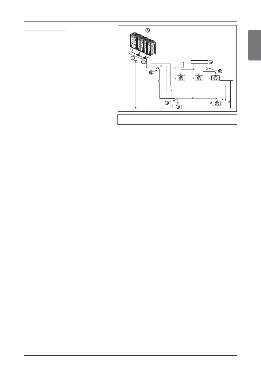
u Y branch method
Refrigerant piping system
1 Outdoor Units
Example : 5 Indoor Units connected
Ⓐ : Outdoor Unit
Ⓑ : 1st branch (Y branch)
Ⓒ : Indoor Units
Master
Master
Slave
Slave
Master
Slave
33ft
(10m)
or
less
l
131ft(40m) (295ft(90m) : Conditional application)
H 361ft(110m)
L492ft(150m) (656ft(200m) : Conditional application)
ODU Capacity
Master ≥ Slave
49ft(15m)
2 Outdoor Units
Example : 5 Indoor Units connected
Ⓐ : Outdoor Unit
Ⓑ : 1st branch (Y branch)
Ⓒ : Indoor Units
Ⓓ : Downward Indoor Unit
Ⓔ : Connection branch pipe
between Outdoor units:
ARCNN21
l
131ft(40m) (295ft(90m) : Conditional application)
H 361ft(110m)
49ft(15m)
L492ft(150m) (656ft(200m) : Conditional application)
Piping length from outdoor branch to outdoor unit ≤ 33ft(10m), equivalent length:max 43ft(13m) (for
12ton(14HP) or more)
Additional Application
To satisfy below condition to make 131ft(40m) ~ 295ft(90m) of pipe length after first branch.
1) Diameter of pipes between first branch and the last branch should be increased by one step,
except pipe diameter B,C,D is same as Diameter A
Ø1/4(6.35mm)→Ø3/8(9.52mm)→Ø1/2(12.7mm)→Ø5/8(15.88mm)→Ø3/4(19.05mm)→Ø7/8(22.2mm)→Ø1(25.4)*,
Ø1-1/8(28.58mm)→Ø1-1/4(31.8mm)*,Ø1-3/8(34.9mm)→Ø1-1/2(38.1mm)*
* : It is not necessary to size up.
h If the step up size is not available, you can not select the next higher size available.
2) While calculating whole refrigerant pipe length, pipe B,C,D length should be calculated twice.
A+Bx2+Cx2+Dx2+a+b+c+d+e ≤ 3281ft(1000m)
3) Length of pipe from each indoor unit to the closest branch (a,b,c,d,e) ≤ 131ft(40m)
4) [Length of pipe from outdoor unit to the farthest indoor unit 5 (A+B+C+D+e)]
- [Length of pipe from outdoor unit to the closest indoor unit 1 (A+a)] ≤ 131ft(40m)
32 Outdoor Unit
Pipe connections between indoor and outdoor unit
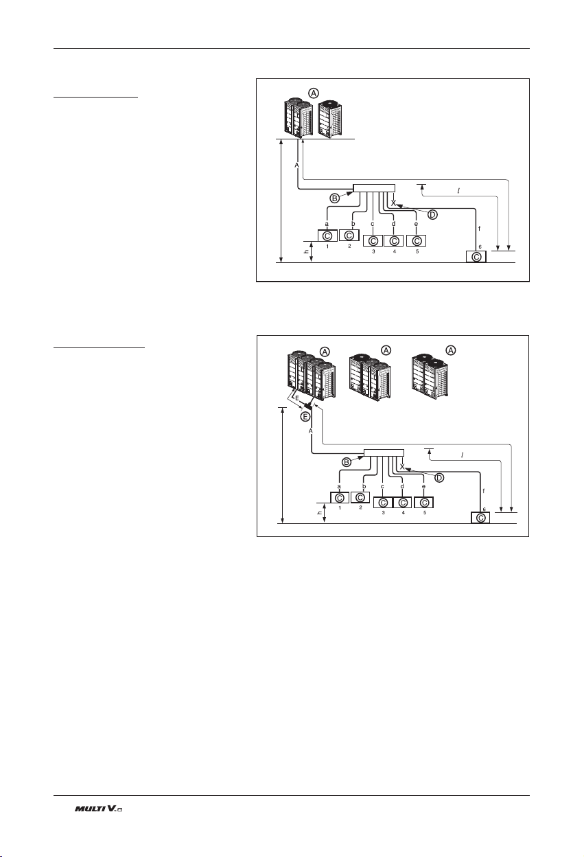
323ft
(10m) or
less
L492ft(150m) (656ft(200m) : Conditional application)
ODU Capacity
Master ≥ Slave1 ≥ Slave 2
l
131ft(40m) (295ft(90m) : Conditional application)
H 361ft(110m)
49ft(15m)
Slave2
Slave1
Master
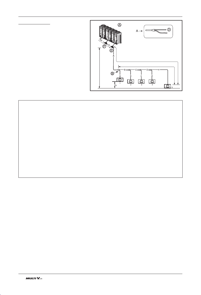
3 Outdoor Units
Example : 5 Indoor Units
connected
Ⓐ : Outdoor Unit
Ⓑ : 1st branch (Y branch)
Ⓒ : Indoor Units
Ⓓ : Downward Indoor Unit
Ⓔ : Connection branch pipe
between Outdoor units:
ARCNN31
Ⓕ : Connection branch pipe
between Outdoor units:
ARCNN21
Piping length form outdoor branch to outdoor unit ≤ 33ft(10m), equivalent length : max. 43ft(13m)(for
12ton(14HP) or more)
Additional Application
To satisfy below condition to make 131ft(40m) ~ 295ft(90m) of pipe length after first branch.
1) Diameter of pipes between first branch and the last branch should be increased by one step, except
pipe diameter B,C,D is same as Diameter A
Ø1/4(6.35mm)→Ø3/8(9.52mm)→Ø1/2(12.7mm)→Ø5/8(15.88mm)→Ø3/4(19.05mm)→Ø7/8(22.2mm)→Ø1(25.4)*,
Ø1-1/8(28.58mm)→Ø1-1/4(31.8mm)*,Ø1-3/8(34.9mm)→Ø1-1/2(38.1mm)*
* : It is not necessary to size up.
h If the step up size is not available, you can not select the next higher size available.
2) While calculating whole refrigerant pipe length, pipe B,C,D length should be calculated twice.
A+Bx2+Cx2+Dx2+a+b+c+d+e ≤ 3281ft(1000m)
3) Length of pipe from each indoor unit to the closest branch (a,b,c,d,e) ≤ 131ft(40m)
4) [Length of pipe from outdoor unit to the farthest indoor unit 5 (A+B+C+D+e)]
- [Length of pipe from outdoor unit to the closest indoor unit 1 (A+a)] ≤ 131ft(40m)
ENGLISH
Installation Manual 33
Pipe connections between indoor and outdoor unit
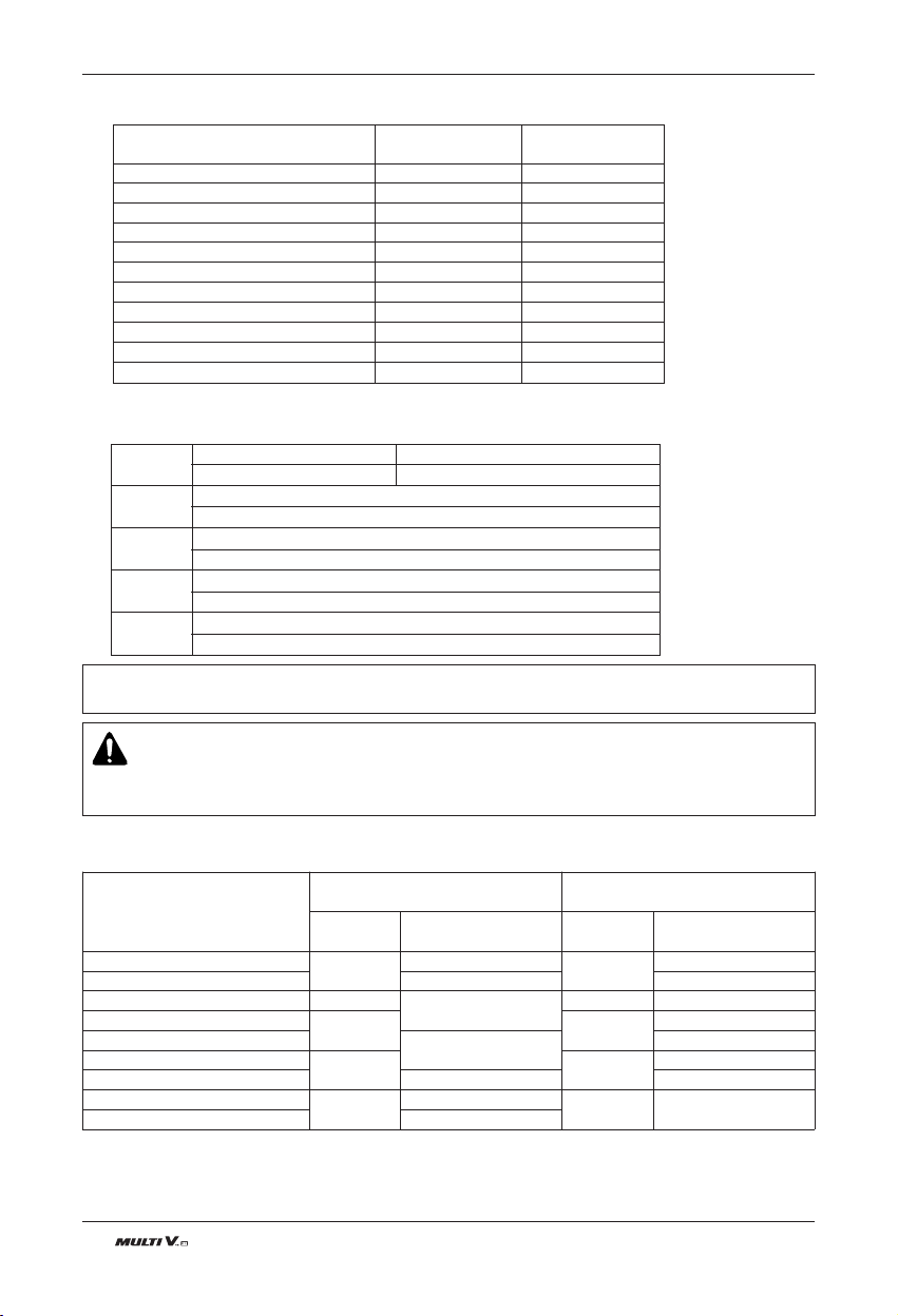
Ú Refrigerant pipe diameter from branch to branch (B,C,D)
Ú Total pipe length = A+B+C+D+a+b+c+d+e ≤ 3281ft(1000m)
• * : Assume equivalent piping length of Y branch to be 1.6ft(0.5m), that of header to be 3.3ft(1m), calculation
purpose.
• ** : To apply Conditional Application
Downward Indoor Unit total capacity
[kW(Btu/h)]
≤ 5.6(19,100) 1/4(Ø6.35) 1/2(Ø12.7)
< 16.0(54,600) 3/8(Ø9.52) 5/8(Ø15.88)
≤ 22.4(76,400) 3/8(Ø9.52) 3/4(Ø19.05)
< 33.6(114,700) 3/8(Ø9.52) 7/8(Ø22.2)
< 50.4(172,000) 1/2(Ø12.7) 1
1
/8( Ø28.58)
< 67.2(229,400) 5/8(Ø15.88) 1
1
/8 (Ø28.58)
< 72.8(248.500) 5/8(Ø15.88) 1
3
/8(Ø34.9)
< 100.8(344,000) 3/4(Ø19.05) 1
3
/8(Ø34.9)
< 173.6(592,500) 3/4(Ø19.05) 1
5
/8(Ø41.3)
< 184.8(630,700) 7/8(Ø22.2) 1
3
/4(Ø44.5)
< 224.0(764,400) 7/8(Ø22.2) 2(Ø53.98)
Liquid pipe
[inch(mm)]
Gas pipe
[inch(mm)]
Longest pipe length Equivalent pipe length
A+B+C+D+e ≤ 492ft(656ft**(200m))
*
A+B+C+D+e ≤ 574ft(656ft**(200m))
Longest pipe length after 1st branch
B+C+D+e ≤ 131ft**(40m))
Difference in height(Outdoor Unit ÷ Indoor Unit)
H ≤ 361ft(110m)
Difference in height (Indoor Unit ÷ Indoor Unit)
h ≤ 49ft(15m)
Difference in height (Outdoor Unit ÷ Outdoor Unit)
h1 ≤ 16.4ft(5m)
L
l
H
h
h1
WARNING
If overall equivalent pipe length is greater than or equal to 295ft(90m) from ODU to the longest IDU,
The diameter of the main pipe (Gas and Liquid pipes) must be increased as follow.
Ú Refrigerant pipe diameter from outdoor unit to first branch. (A)
h If the step up size is not available, you can not select the next higher size available.
Outdoor unit
Total capacity
[kW (Btu/h)
Standard Pipe Diameter
Conditional application
(more than 90m from ODU to IDU)
Liquid pipe
[mm (inch)]
Gas pipe
[mm (inch)]
Liquid pipe
[mm (inch)]
Gas pipe
[mm (inch)]
16.0~22.4(54,600~76,400)
Φ9.52(3/8)
Φ19.05(3/4)
Φ12.7(1/2)
Φ22.2(7/8)
28.0(95,900)
Φ22.2(7/8) Φ25.4(1)
33.6~44.8(172,000~152,900)
Φ12.7(1/2)
Φ28.58(1 1/8)
Φ15.88(5/8)
Φ28.58(1 1/8)
50.4~61.6(172,000~210,600)
Φ15.88(5/8) Φ19.05(3/4)
Φ31.8(1 1/4)
67.2(229,400)
Φ34.9(1 3/8)
Φ34.9(1 3/8)
72.8~95.2(248,500~324,900)
Φ19.05(3/4) Φ22.2(7/8)
Φ38.1(1 1/2)
100.8~168.0(344,000~573,300)
Φ41.3(1 5/8) Φ41.3(1 5/8)
173.6~179.2(592,500~611,600)
Φ22.2(7/8)
Φ44.5(1 3/4)
Φ25.4(1)
Φ53.98(2)
184.8~224.0(630,700~764,400)
Φ53.98(2)
34 Outdoor Unit
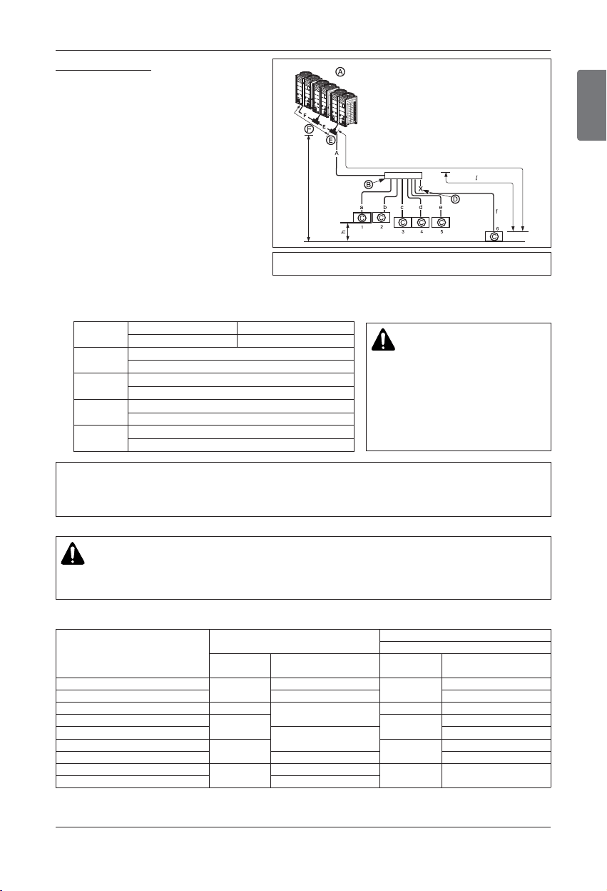
Pipe connections between indoor and outdoor unit
1 Outdoor Unit
Example : 6 Indoor Units connected
Ⓐ : Outdoor Unit
Ⓑ : 1st branch
Ⓒ : Indoor Units
Ⓓ : Sealed piping
L 656ft(200m)
131ft(40m)
H 361ft(110m)
49ft(15m)
33ft
(10m) or
less
L 361ft(110m)
49ft(15m)
L 656ft(200m)
131ft(40m)
Slave
Master
Slave
Master
Slave
Master
ODU Capacity
Master Slave
2 Outdoor Units
Example : 6 Indoor Units connected
Ⓐ : Outdoor Unit
Ⓑ : Header branch
Ⓒ : Indoor Units
Ⓓ : Sealing
Ⓔ : Connection branch pipe be-
tween Outdoor units:
ARCNN21
u Header Method
ENGLISH
Installation Manual 35
Pipe connections between indoor and outdoor unit
Longest pipe length * Equivalent pipe length
A+f ≤ 656ft(200m) A+f ≤ 738ft(225m)
Longest pipe length after 1st branch
f ≤ 131ft(40m)
Difference in height(Outdoor Unit ÷ Indoor Unit)
H ≤ 361ft(110m)
Difference in height (Indoor Unit ÷ Indoor Unit)
h ≤ 49ft(15m)
Difference in height
(Outdoor Unit
÷
Outdoor Unit)
h1 ≤ 16ft(5m)
L
l
H
h
h1
Ú Total pipe length = A+a+b+c+d+e+f ≤ 3280.8ft(1000m)
WARNING
Pipe length after header branching
(a~f)
It is recommended that difference in
length of the pipes connected to the
Indoor Units is minimized.
Performance difference between
Indoor Units may occur.
• * :
Assume equivalent piping length of Y branch to be 1.6ft(0.5m), that of header to be 3.3ft(1m), calculation purpose
• It is recommended that indoor unit Is installed at lower position than the header.
• Piping length from outdoor branch to outdoor unit ≤ 33ft(10m), equivalent length : max 43ft(13m)
(for 12ton(14HP) or more)
Branch pipe can not be used after header
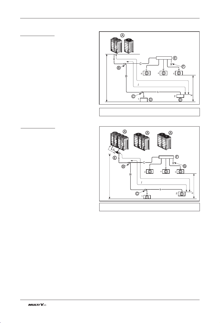
3 Outdoor Units
Example : 6 Indoor Units connected
Ⓐ : Outdoor Unit
Ⓑ : Header branch
Ⓒ : Indoor Units
Ⓓ : Sealing
Ⓔ : Connection branch pipe
between Outdoor units:
ARCNN31
Ⓕ : Connection branch pipe
between Outdoor units:
ARCNN21
33ft
(10m)
or less
H 361ft(110m)
49ft(15m)
L 656ft(200m)
131ft(40m)
Master
Slave2
Slave1
ODU Capacity
Master ≥ Slave1 ≥ Slave2
WARNING
If overall equivalent pipe length is greater than or equal to 295ft(90m) from ODU to the longest IDU,
The diameter of the main pipe (Gas and Liquid pipes) must be increased as follow.
Ú Refrigerant pipe diameter from outdoor unit to first branch. (A)
h If the step up size is not available, you can not select the next higher size available.
Outdoor unit
Total capacity
[kW (Btu/h)
Standard Pipe Diameter
Conditional application
(more than 90m from ODU to IDU)
Liquid pipe
[mm (inch)]
Gas pipe
[mm (inch)]
Liquid pipe
[mm (inch)]
Gas pipe
[mm (inch)]
16.0~22.4(54,600~76,400)
Φ9.52(3/8)
Φ19.05(3/4)
Φ12.7(1/2)
Φ22.2(7/8)
28.0(95,900)
Φ22.2(7/8) Φ25.4(1)
33.6~44.8(172,000~152,900)
Φ12.7(1/2)
Φ28.58(1 1/8)
Φ15.88(5/8)
Φ28.58(1 1/8)
50.4~61.6(172,000~210,600)
Φ15.88(5/8) Φ19.05(3/4)
Φ31.8(1 1/4)
67.2(229,400)
Φ34.9(1 3/8)
Φ34.9(1 3/8)
72.8~95.2(248,500~324,900)
Φ19.05(3/4) Φ22.2(7/8)
Φ38.1(1 1/2)
100.8~168.0(344,000~573,300)
Φ41.3(1 5/8) Φ41.3(1 5/8)
173.6~179.2(592,500~611,600)
Φ22.2(7/8)
Φ44.5(1 3/4)
Φ25.4(1)
Φ53.98(2)
184.8~224.0(630,700~764,400)
Φ53.98(2)
36 Outdoor Unit
Pipe connections between indoor and outdoor unit
u Combination of Y branch/header method
1 Outdoor Units
Example : 5 Indoor Units connected
Ⓐ : Outdoor Unit
Ⓑ : 1st branch (Y branch)
Ⓒ : Y branch
Ⓓ : Indoor Unit
Ⓔ : Header
Ⓕ : Sealed piping
L 492ft(150m)(656ft(200m) : Conditional application)
131ft(40m)(295ft(90m) : Conditional application)
L 361ft(110m)
49ft(15m)
Branch pipe can not be used after header
Branch pipe can not be used after header
2 Outdoor Units
Example : 5 Indoor Units connected
Ⓐ : Outdoor Unit
Ⓑ : 1st branch
Ⓒ : Y branch
Ⓓ : Indoor Unit
Ⓔ : Connection branch pipe be-
tween Outdoor units:
ARCNN21
Ⓕ : Header
Ⓖ : Sealed piping
33ft
(10m)
or less
H 361ft(110m)
49ft(15m)
Master
Slave
Master
Slave
Master
Slave
L 492ft(150m)(656ft(200m) : Conditional application)
131ft(40m)(295ft(90m) : Conditional application)
ODU Capacity
Master Slave
ENGLISH
Installation Manual 37
Pipe connections between indoor and outdoor unit
Branch pipe can not be used after header
3 Outdoor Units
Example : 5 Indoor Units connected
Ⓐ : Outdoor Unit
Ⓑ : 1st branch(Y branch)
Ⓒ : Y branch
Ⓓ : Indoor Unit
Ⓔ : Connection branch pipe be-
tween Outdoor units:
ARCNN31
Ⓕ : Connection branch pipe be-
tween Outdoor units:
ARCNN21
Ⓖ : Header
Ⓗ : Sealing
33ft
(10m)
or less
H 361ft(110m)
49ft(15m)
Master
Slave2
Slave1
F
E
F
E
ODU Capacity
Master ≥ Slave1 ≥ Slave2
L 492ft(150m)(656ft(200m) : Conditional application)
131ft(40m)(295ft(90m) : Conditional application)
38 Outdoor Unit
Pipe connections between indoor and outdoor unit
Ú Refrigerant pipe diameter from branch to branch (B,C)
Ú Total pipe length = A+B+C+a+b+c+d+e ≤ 3280.8ft(1000m)
Longest pipe length * Equivalent pipe length
A+B+b ≤ 492ft(656ft(200m)**)
A+B+b ≤ 574ft(738ft(225m)**)
Longest pipe length after 1st branch
B+b ≤ 131ft(40m)(295ft(90m)**)
Difference in height(Outdoor Unit ÷ Indoor Unit)
H ≤ 361ft(110m)
Difference in height (Indoor Unit ÷ Indoor Unit)
h ≤ 49ft(15m)
Difference in height (Outdoor Unit ÷ Outdoor Unit)
h1 ≤ 16ft(5m)
L
l
H
h
h1
• * :
Assume equivalent pipe length of Y branch to be 1.6ft(0.5m), that of header to be 3.3ft(1m), calculation purpose
• It is recommended that indoor unit is installed at lower position than the header.
Downward Indoor Unit total capacity
[kW(Btu/h)]
≤ 5.6(19,100) Ø6.35(1/4) Ø12.7(1/2)
< 16.0(54,600) Ø9.52(3/8) Ø15.88(5/8)
≤ 22.4(76,400) Ø9.52(3/8) Ø19.05(3/4)
< 33.6(114,700) Ø9.52(3/8) Ø22.2(7/8)
< 50.4(172,000) Ø12.7(1/2) Ø28.58(1
1
/8 )
< 67.2(229,400) Ø15.88(5/8) Ø28.58(1
1
/8 )
< 72.8(248.500) Ø15.88(5/8) Ø34.9(1
3
/8)
< 100.8(344,000) Ø19.05(3/4) Ø34.9(1
3
/8)
< 173.6(592,500) Ø19.05(3/4) Ø41.3(1
5
/8)
< 184.8(630,700) Ø22.2(7/8) Ø44.5(1
3
/4)
< 224.0(764,400) Ø22.2(7/8) Ø53.98(2)
Liquid pipe
[inch(mm)
Gas pipe
[inch(mm)
h If available on site, it use this size. Otherwise it can't be increased.
WARNING
If overall equivalent pipe length is greater than or equal to 295ft(90m) from ODU to the longest IDU,
The diameter of the main pipe (Gas and Liquid pipes) must be increased as follow.
Ú Refrigerant pipe diameter from outdoor unit to first branch. (A)
Outdoor unit
Total capacity
[kW (Btu/h)
Standard Pipe Diameter
Conditional application
(more than 90m from ODU to IDU)
Liquid pipe
[mm (inch)]
Gas pipe
[mm (inch)]
Liquid pipe
[mm (inch)]
Gas pipe
[mm (inch)]
16.0~22.4(54,600~76,400)
Φ9.52(3/8)
Φ19.05(3/4)
Φ12.7(1/2)
Φ22.2(7/8)
28.0(95,900)
Φ22.2(7/8) Φ25.4(1)
33.6~44.8(172,000~152,900)
Φ12.7(1/2)
Φ28.58(1 1/8)
Φ15.88(5/8)
Φ28.58(1 1/8)
50.4~61.6(172,000~210,600)
Φ15.88(5/8) Φ19.05(3/4)
Φ31.8(1 1/4)
67.2(229,400)
Φ34.9(1 3/8)
Φ34.9(1 3/8)
72.8~95.2(248,500~324,900)
Φ19.05(3/4) Φ22.2(7/8)
Φ38.1(1 1/2)
100.8~168.0(344,000~573,300)
Φ41.3(1 5/8) Φ41.3(1 5/8)
173.6~179.2(592,500~611,600)
Φ22.2(7/8)
Φ44.5(1 3/4)
Φ25.4(1)
Φ53.98(2)
184.8~224.0(630,700~764,400)
Φ53.98(2)
ENGLISH
Installation Manual 39
Pipe connections between indoor and outdoor unit
u Outdoor unit Connection
u Indoor Unit Connection
Ú Indoor Unit connecting pipe from branch (a,b,c,d,e,f)
WARNING
• In case of pipe diameter B connected after first branch is bigger than the main pipe diameter A, B should be of the same
size with A.
Ex) In case indoor unit combination ratio 120% is connected to 70kW outdoor unit.
1) Outdoor unit main pipe diameter A : Ø34.9(1-3/8, gas pipe), Ø15.88(5/8, liquid pipe)
2) Pipe diameter B after first branch according to 120% indoor unit combination(84kW) : Ø34.9(1-3/8, gas pipe),
Ø19.05(3/4, liquid pipe)
Therefore, pipe diameter B connected after first branch would be Ø34.9(1-3/8, gas pipe) / Ø15.88(5/8, liquid pipe)
which is same with main pipe diameter.
[Example]
Instead of using indoor unit total capacity, use outdoor unit model name in order to choose main pipe diameter by
downward.
Do not let the connection pipe from branch to branch exceed the main pipe diameter chosen by outdoor unit model name.
EX) Where connecting the indoor units to the 22 HP (61.6kW) outdoor unit to 120% of its system capacity (73.8 kW) and
branching 7k Btu/h(2.2kW) indoor unit at the 1st branch
Main pipe diameter(22 HP outdoor unit): Ø28.58(1-1/8, Gas pipe) Ø15.88(5/8, Liquid pipe)
Pipe diameter between 1st and 2nd branch (71.7kW indoor units):
Ø34.9(1-3/8, Gas pipe) Ø19.05(3/4, Liquid pipe) in conformity with downward indoor units.
Since the main pipe diameter of 22HP outdoor unit is Ø28.58(1-1/8, Gas pipe) and Ø15.88(5/8, Liquid pipe), Ø28.58 (1-
1/8, Gas pipe) and Ø15.88(5/8, Liquid pipe) is used as the main pipe and the connection pipe between 1st and 2nd
branch.
* High/Low Pressure Common Pipe: Ø19.05(3/4) ; 14HP or more
Indoor Unit capacity [kW(Btu/h)]
≤ 5.6(19,100)
< 16.0(54,600)
≤ 22.4(76,400)
Ø6.35(1/4)
Ø9.52(3/8)
Ø9.52(3/8)
Ø12.7(1/2)
Ø15.88(5/8)
Ø19.05(3/4)
Liquid pipe
[mm(inch)]
Gas pipe
[mm(inch)]
*
ARNU093TN*2, ARNU123TN*2, ARNU153TN*2, ARNU183TM*2, ARNU243TM*2 : Liquid pipe Ø9.52(3/8), Gas pipe
Ø15.88(5/8)
ARNU153BG*2, ARNU183BG*2, ARNU243BG*2 : Liquid pipe Ø9.52(3/8), Gas pipe Ø15.88(5/8)
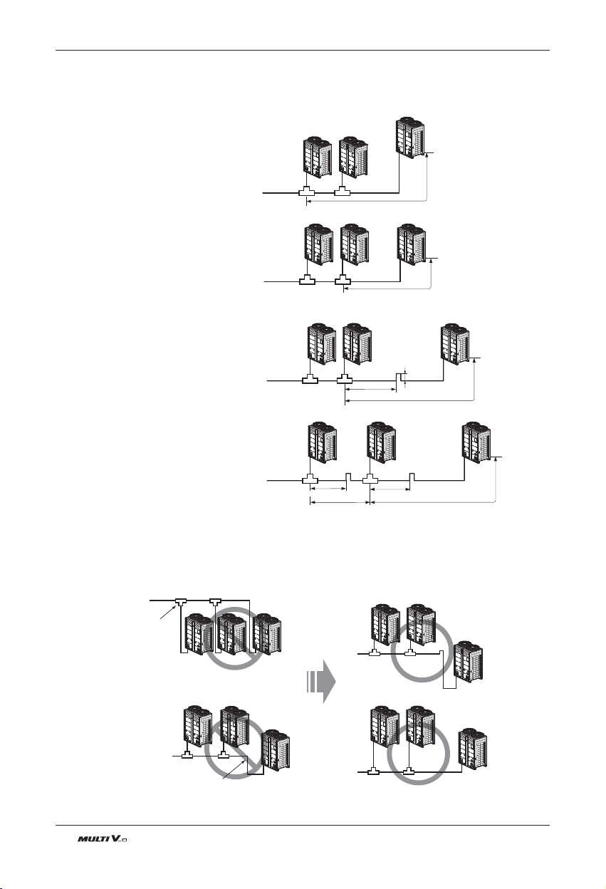
40 Outdoor Unit
Pipe connections between indoor and outdoor unit
n Pipe connection between outdoor units
(General Case)
n Pipes between outdoor units are
2m(6.6ft) or less
n Pipes between outdoor units are
2m(6.6ft) or longer
n Examples of Wrong Pipe Connections
The maximum pipe length
after the first branching
between the outdoor units is
10m(33ft) or less
2m(6.6)ft or less
Oil Trap
Oil Trap Oil Trap
2m(6.6ft) or less
2m(6.6ft) or less
2m(6.6ft) or less
0.2m(0.66ft) or more
2m(6.6ft) or longer
2m(6.6ft) or longer2m(6.6ft) or longer
• If the distance between the outdoor units becomes more than 2m(6.6ft), apply Oil Traps between the gas pipes.
• If the outdoor unit is located lower than the main pipe, apply Oil Trap.
If the main pipe is higher
than the outdoor units, oil
is accumulated in the
outdoor unit.
If there are differences in the height
between the outdoor units, oil is
accumulated in the lower outdoor unit.
Oil Trap
u Pipe Connection Method/Precautions for Series connections between Outdoor units
- Separate Y branch joints are needed for series connections between outdoor units.
- Please refer to the below connection examples to install pipe connections between outdoor units.
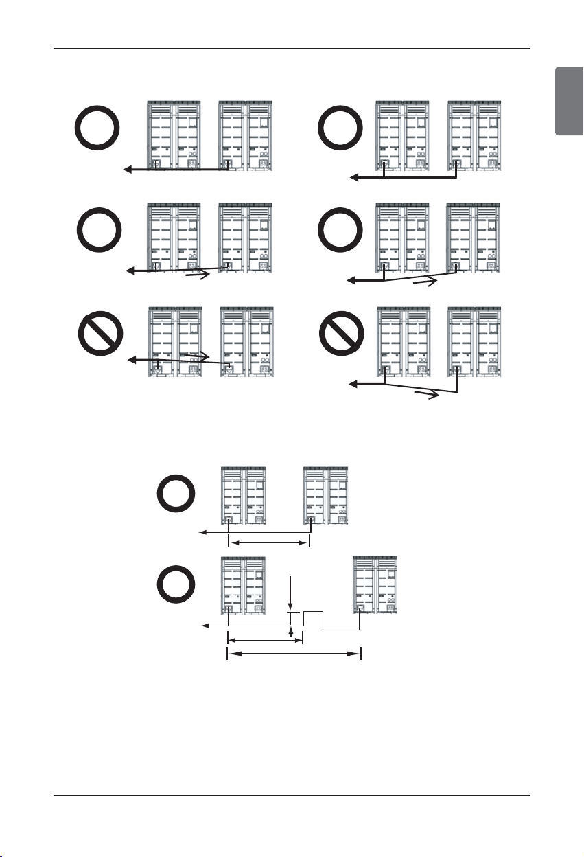
ENGLISH
Installation Manual 41
Pipe connections between indoor and outdoor unit
• The pipes between the outdoor units must maintain level or give an inclination to prevent a back flow toward the slave
outdoor unit. Otherwise, the unit may not operate properly.
• Apply Oil Trap only to gas pipe as shown below when the length of the pipe between the outdoor units is over 2m(6.6ft).
Otherwise, the unit may not operate properly.
Toward indoor unit
(Example 1)
(Example 2)
(Example 3)
Toward indoor unit
Pipe inclination (2 or more)
Toward indoor unit
Toward indoor unit
Toward indoor unit
Toward indoor unit
Toward indoor unit
Toward indoor unit
≤
2m(6.6ft)
2m(6.6ft)
> 2m(6.6ft)
≥
0.2m(6.6ft)
Oil Trap
≤
(Example 1)
(Example 2)
* Install oil trap if the ODU is at lower level than main piping.
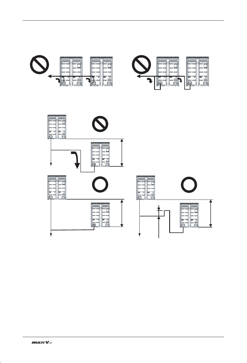
42 Outdoor Unit
Pipe connections between indoor and outdoor unit
* The level difference between two outdoor units, h is allowed up to 5m(16.4ft).
• When connecting the pipes between the outdoor units, the accumulation of oil in the slave outdoor unit should be avoided.
Otherwise, the unit may not operate properly.
Toward indoor unit
Toward indoor unit
(Example 1)
(Example 2)
(Example 3)
h
h
h
≥
0.2m(6.6ft)
Toward indoor unit
Toward indoor unit Toward indoor unit
Oil Trap
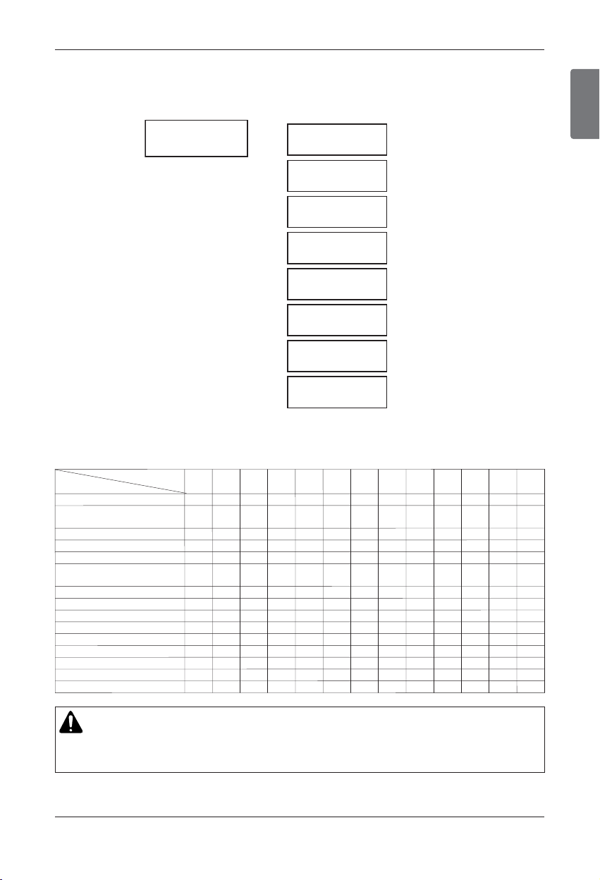
ENGLISH
Installation Manual 43
Pipe connections between indoor and outdoor unit
u
The amount of Refrigerant
The calculation of the additional charge should take into account the length of pipe and CF(correction
Factor) value of indoor unit.
Additional charge(kg)
+
+
+
+
+
+
+
=
Total liquid pipe
:Ø25.4 mm (1.0 inch)
0.323(lbs/ft)
0.238(lbs/ft)
0.179(lbs/ft)
0.116(lbs/ft)
0.079(lbs/ft)
0.041(lbs/ft)
0.015(lbs/ft)
x
x
x
x
x
x
x
Total liquid pipe
:Ø22.2 mm (7/8 inch)
Total liquid pipe
:Ø19.05 mm (3/4 inch)
Total liquid pipe
:Ø15.88 mm (5/8 inch)
Total liquid pipe
:Ø12.7 mm (1/2 inch)
Total liquid pipe
:Ø9.52 mm (3/8 inch)
Total liquid pipe
:Ø6.35 mm(1/4 inch)
CF value of indoor unit
CF value of indoor unit (Unit: lbs)
Capacity(Btu/h(kW))
5k
7k
9k 12k 15k 18k 24k 28k 36k 42k 48k 76k 96k
Type
Ceiling Concealed Duct (Low Static)
Ceiling Concealed Duct (High Static)
Wall Mounted
1Way Ceiling Cassette
2Way Ceiling Cassette
4Way Ceiling Cassette
ARTCOOL Gallery
Floor Standing
Ceiling & Floor
Ceiling Suspended
Console
Fresh Air Intake Unit
Heat recovery ventilator(DX)
Hydro kit
Vertical AHU
- 0.37 0.37 0.37 0.37 0.82 0.82 - - - - - -
- 0.57 0.57 0.57 0.57 0.57 0.57 0.97 0.97 0.97 1.37 2.20 2.20
0.97
#
0.97
#
0.97
#
- 0.53 0.53 0.53 0.53 0.62 0.62 - - - - - -
- 0.44 0.44 0.44 - 0.64 0.64 - - - - - -
- - - - - 0.35 0.35 - - - - - -
0.40 0.40 0.55 0.55 0.71 0.71 1.06 1.06 1.41 1.41 1.41 - -
1.06
##
1.06
##
1.06
##
1.41
##
1.41
##
- 0.22 0.22 0.22 - - - - - - - - -
- 0.37 0.37 0.37 0.37 0.82 0.82 - - - - - -
- - 0.22 0.22 - - - - - - - - -
- 0.77 0.77 - 1.19 - 1.65 - - - - - -
- 0.37 0.37 0.37 0.37 - - - - - - - -
- - - - - - - - - - 1.37 2.20 2.20
- - - 0.44 - 0.44 0.44 - - - - - -
- - - - - - - - - - - - 3.53
- - - - - 1.04 1.04 - 1.57 2.00 2.00 2.00 2.00
CAUTION
Use only 2-series of indoor unit. Ex) ARNU***2
# : Use only ARNU153BGA2, ARNU183BGA2, ARNU243BGA2
##: Use only ARNU093TN*2, ARNU123TN*2, ARNU153TN*2, ARNU183TM*2, ARNU243TM*2
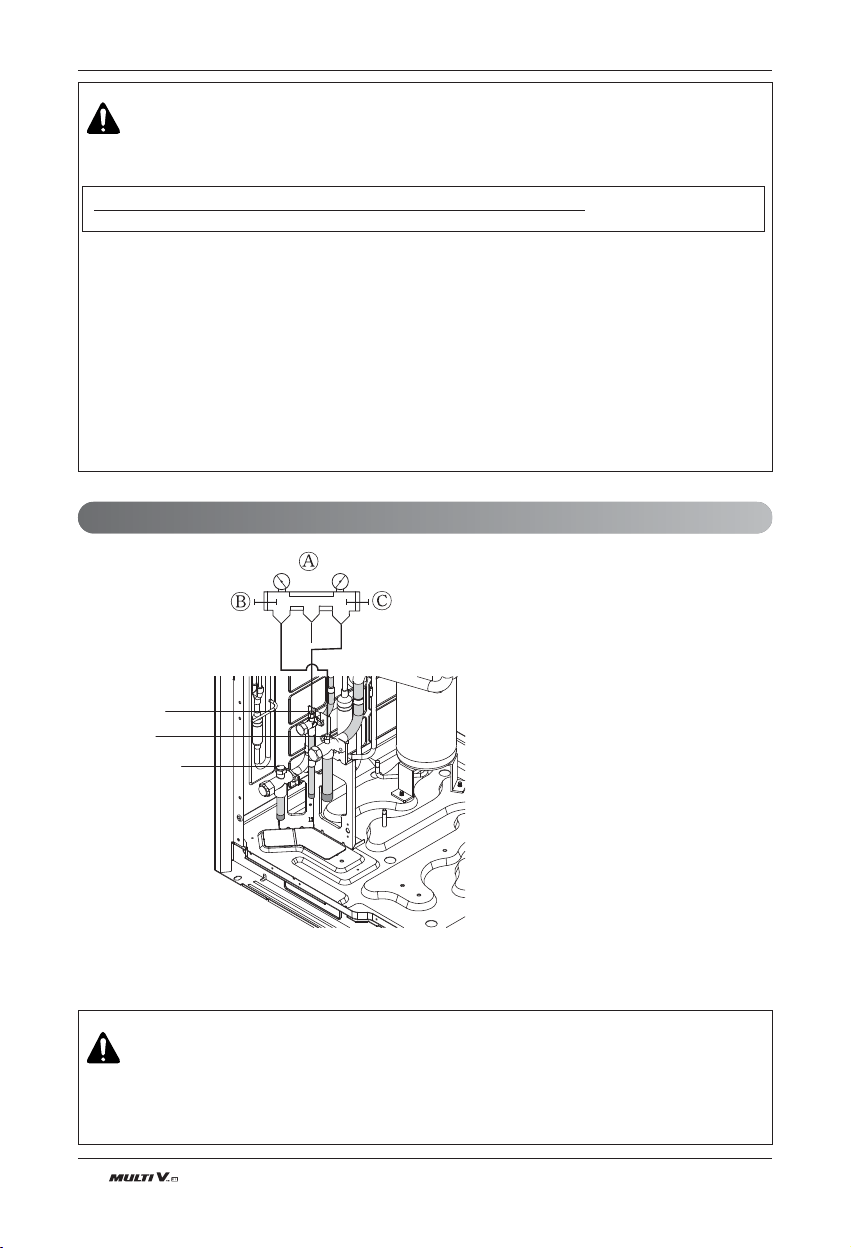
44 Outdoor Unit
Pipe connections between indoor and outdoor unit
WARNING
▶ Regulation for refrigerant leakage
: the amount of refrigerant leakage should satisfy the following equation for human safety.
p If the above equation can not be satisfied, then follow the following steps.
- Selection of air conditioning system: select one of the next
1. Installation of effective opening part
2. Reconfirmation of Outdoor Unit capacity and piping length
3. Reduction of the amount of refrigerant
4. Installation of 2 or more security device (alarm for gas leakage)
- Change Indoor Unit type
: installation position should be over 6.6ft from the floor (Wall mounted type ’ Cassette type)
- Adoption of ventilation system
: choose ordinary ventilation system or building ventilation system
- Limitation in piping work
: Prepare for earthquake and thermal stress
Total amount of refrigerant in the system
≤ 0.44(kg/m
3
(0.028 (lbs/ft³))
Volume of the room at which Indoor Unit of the least capacity is installed
- Add exact amount of refrigerant calculated by the installation pipe diameter length and the indoor combination.
- If the refrigerant amount is not exact, it may not operate properly.
-
If additionally bottled refrigerant amount is over ±10%, condenser burning or insufficient indoor unit performance may be caused.
Liquid pipe
Gas pipe
Common pipe
Ⓐ Manifold Gauge
Ⓑ Low pressure side Handle
Ⓒ High pressure side Handle
Refrigerant Charging
WARNING
- Pipe to be vacuumed : gas pipe, water pipe, common pipe
- If the refrigerant amount is not exact, it may not operate properly.
- If additionally bottled refrigerant amount is over ±10%, condenser burning or insufficient indoor unit per-
formance may be caused.
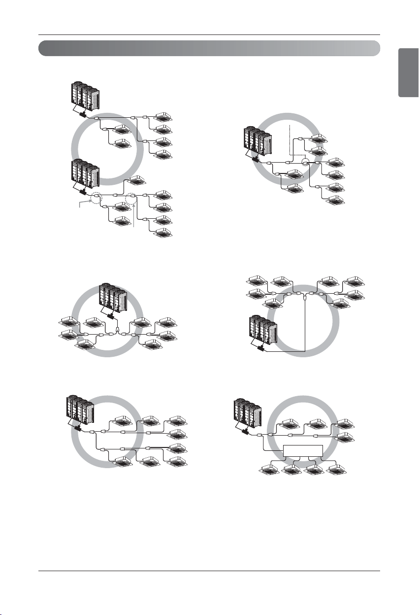
ENGLISH
Installation Manual 45
Pipe connections between indoor and outdoor unit
1. Line Distribution
2. Vertical Distribution
Ensure that the branch pipes are attached vertically.
3. The others
Header
Slave
Master
Slave
Master
1st
1st
1st
Main pipe
Distribution
2nd
2nd
3rd
Slave
Master
Slave
Master
Slave
Master
Slave
Master
3rd
Main pipe
Distribution
Slave
Master
1st
3rd
3rd main pipe distribution
2nd
Distribution Method

46 Outdoor Unit
Pipe connections between indoor and outdoor unit
Branch pipe Fitting
Y branch
A
B
To Outdoor Unit
To Branch Piping or Indoor Unit
A
B
Facing
upwards
Facing
downwards
Within 3 Within 3
Viewed from point A
in direction of arrow
Horizontal
plane
Within +/- 10
A
Insulator
(included with kit)
Liquid and gas
pipe joints
Insulator for
field piping
Tap e
(field supply)
A
B
Header
To outdoor unit
To indoor unit
A
B
C
• Ensure that the branch pipes are attached horizontally or vertically (see the diagram below.)
• There is no limitation on the joint mounting configuration.
• If the diameter of the refrigerant piping selected by the procedures described is different from the size of
the joint, the connecting section should be cut with a pipe cutter.
• Branch pipe should be insulated with the insulator in each kit.
• When the number of pipes to be connected is
smaller than the number of header branches, in-
stall a cap to the unconnected branches.
• The indoor unit having larger capacity must be
installed closer to Ⓐ than smaller one.
• If the diameter of the refrigerant piping selected
by the procedures described is different from
the size of the joint,
the connecting section
should be cut with a pipe cutter.
ⓒ Pipe cutter
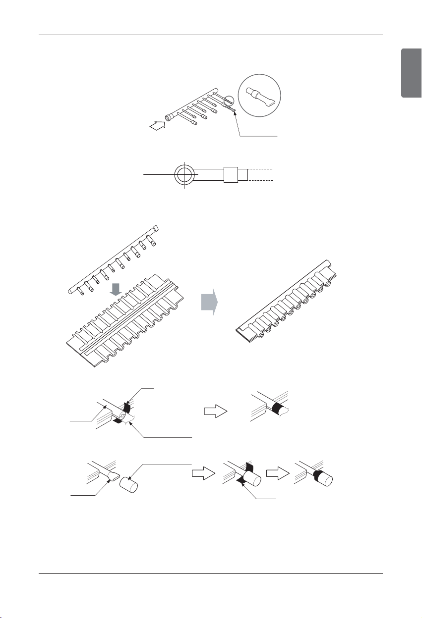
ENGLISH
Installation Manual 47
Pipe connections between indoor and outdoor unit
• When the number of indoor units to be connected to the branch pipes is less than the number of branch pipes
available for connection then cap pipes should be fitted to the surplus branches.
• Fit branch pipe lie in a horizontal plane.
• Header should be insulated with the insulator in each kit.
• Joints between branch and pipe should be sealed with the tape included in each kit.
• Any cap pipe should be insulated using the insulator provided with each kit and then taped as described above.
B
Pinched pipe
Horizontal plane
View from point B in the direction of the arrow
Insulate the header using
the insulation
material attached to the
branch pipe kit
as shown in the figure.
Insulator
Insulator of field pipe
Tape
Tape
Cap pipe
Insulator for cap pipe
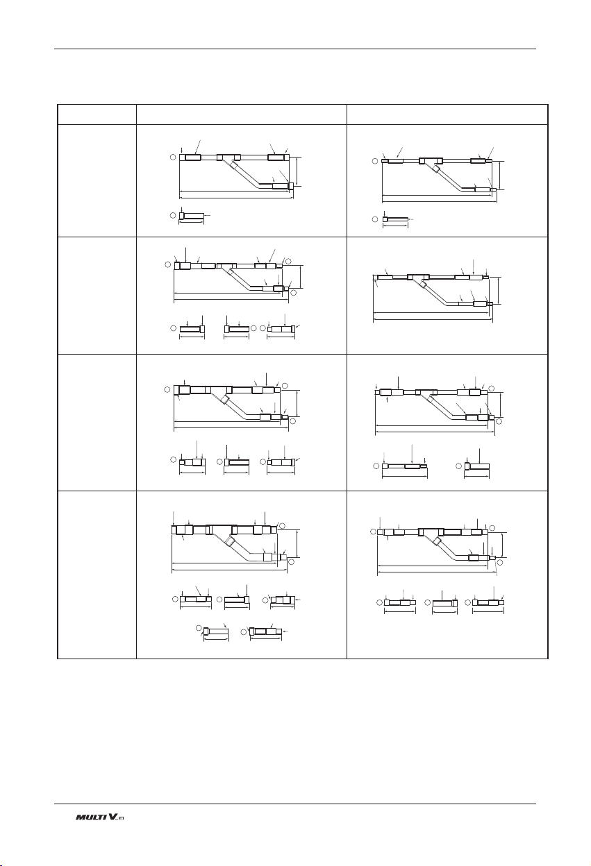
48 Outdoor Unit
Pipe connections between indoor and outdoor unit
u Y branch pipe
Gas pipe Liquid pipe
[Unit:mm(inch)]
Models
ARBLN01621
ARBLN03321
ARBLN07121
ARBLN14521
I.D15.88(5/8)
I.D15.88(5/8)
I.D15.88(5/8)
413(16-1/4)
390(15-11/32)
I.D19.05(3/4)
I.D19.05(3/4)
I.D19.05(3/4)
I.D19.05(3/4)
O.D15.88(5/8)
I.D12.7(1/2)
I.D15.88(5/8)
I.D15.88(5/8)
I.D15.88(5/8)
I.D12.7(1/2)
I.D12.7(1/2)
I.D12.7(1/2)
I.D12.7(1/2)
I.D12.7(1/2)
I.D12.7(1/2)
I.D12.7(1/2)
I.D12.7(1/2)
I.D12.7(1/2)
I.D12.7(1/2)
O.D12.7(1/2)
O.D12.7(1/2)
O.D12.7(1/2)
I.D12.7
(1/2)
I.D12.7
(1/2)
I.D12.7
(1/2)
I.D12.7(1/2)
I.D12.7(1/2)
292(11-1/2)
281(11-1/16)
292(11-1/2)
281(11-1/16)
74
(2-29/32)
74
(2-29/32)
74
(2-29/32)
70(2-3/4)
70(2-3/4)
70(2-3/4)
70(2-3/4)
70(2-3/4)
I.D15.88(5/8)
I.D15.88(5/8)
I.D25.4(1)
I.D25.4(1)
O.D25.4(1)
80(3-5/32)
110(4-11/32)
110(4-11/32)110(4-11/32)
110(4-11/32)
332(13-1/16)
321(12-5/8)
471(18-17/32)
517(20-11/32)
125
(4-29/32)
371(14-19/32)
394(15-1/2)
83
(3-9/32)
83
(3-9/32)
130(5-1/8)
I.D15.88(5/8)
I.D41.3(1-5/8)
I.D41.3
(1-5/8)
I.D41.3(1-5/8)
I.D38.1(1-1/2)
I.D38.1(1-1/2)
I.D38.1(1-1/2)
O.D38.1(1-1/2)
O.D15.88(5/8)
1
2
2
3
3
2
2
3
3
2
3
3
3
376(14-13/16)
404(15-29/32)
120(4-23/32) 120(4-23/32)
120(4-23/32)
120(4-23/32)
90(3-17/32)
90(3-17/32)
I.D15.88(5/8)
I.D15.88(5/8)
2
3
1
2
1 3
3
41616-3/8)
444(17-15/32)
O.D15.88(5/8)
I.D15.88(5/8)
I.D19.05(3/4)
I.D19.05(3/4)
I.D19.05(3/4)
I.D19.05(3/4)
I.D19.05(3/4)
I.D19.05(3/4)
I.D19.05(3/4)
I.D19.05(3/4)
I.D15.88(5/8)
I.D15.88(5/8)
I.D19.05(3/4)
I.D19.05(3/4)
O.D19.05(3/4)
O.D19.05(3/4)
O.D19.05(3/4)
O.D19.05(3/4)
80(3-5/32)
2
3
1
2 3 3
2
1 2
96
(3-25/32)
96
(3-25/32)
I.D22.2(7/8)
I.D22.2(7/8)
I.D22.2(7/8)
I.D22.2(7/8)
I.D22.2(7/8)
I.D22.2(7/8)
I.D22.2(7/8)
I.D22.2(7/8)
O.D22.2(7/8)
O.D22.2(7/8)
I.D22.2(7/8)
I.D22.2(7/8)
I.D6.35(1/4)
I.D6.35(1/4)
I.D6.35(1/4)
I.D6.35(1/4)
I.D6.35(1/4)
I.D6.35(1/4)
I.D6.35(1/4)
1
1
1
1
I.D34.9(1-3/8)
I.D34.9(1-3/8)
I.D34.9(1-3/8)
I.D34.9(1-3/8)
O.D34.9(1-3/8)
I.D28.58(1-1/8)
I.D28.58(1-1/8)
I.D28.58(1-1/8)
I.D28.58(1-1/8)
I.D28.58(1-1/8)
O.D28.58(1-1/8)
I.D28.58(1-1/8)
O.D31.8(1-1/4)
I.D31.8(1-1/4)
I.D31.8(1-1/4)
I.D9.52(3/8)
I.D9.52(3/8)
I.D9.52(3/8)
I.D9.52(3/8)
I.D9.52(3/8)
I.D9.52(3/8)
I.D9.52(3/8)
I.D9.52(3/8)
I.D9.52(3/8)
I.D9.52(3/8)
O.D9.52(3/8)
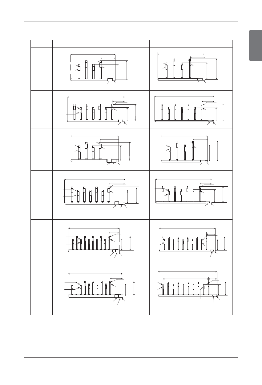
ENGLISH
Installation Manual 49
Pipe connections between indoor and outdoor unit
u Header
[Unit:mm(inch)]
4 branch
ARBL054
7 branch
ARBL057
4 branch
ARBL104
7 branch
ARBL107
10 branch
ARBL1010
10 branch
ARBL2010
Models Gas pipe Liquid pipe
360(14-5/32)
540(21-1/4)
540(21-1/4)
120(4-23/32)
ID15.88(5/8)
ID12.7(1/2)
ID12.7(1/2)
ID15.88(5/8)
ID15.88(5/8)
ID19.05(3/4)
120(4-23/32)
360(14-5/32)
ID9.52(3/8)
ID9.52(3/8)
ID6.35(1/4)
ID6.35(1/4)
ID9.52(3/8)
ID12.7(1/2)
150
(5-29/32)
150
(5-29/32)
150
(5-29/32)
150
(5-29/32)
150
(5-29/32)
400(15-23/32)
160(6-5/16)
ID15.88(5/8)ID15.88(5/8)
ID12.7(1/2)ID12.7(1/2)
ID15.88(5/8)
ID12.7(1/2)
ID19.05(3/4)
ID15.88(5/8)
ID22.2(7/8)
ID28.58(1-1/8)
ID25.4(1)
120
(4-23/32)
120
(4-23/32)
120
(4-23/32)
120
(4-23/32)
120
(4-23/32)
120
(4-23/32)
120
(4-23/32)
120
(4-23/32)
120
(4-23/32)
120(4-23/32)
ID15.88(5/8)
ID12.7(1/2)
ID15.88(5/8)
ID12.7(1/2)
ID15.88(5/8)
ID19.05(3/4)
120(4-23/32)
ID6.35(1/4)
ID9.52(3/8)
ID9.52(3/8)
ID12.7(1/2)
160(6-5/16)
580(22-27/32)
ID19.05(3/4)
ID15.88(5/8)
ID15.88(5/8)ID15.88(5/8)
ID12.7(1/2)ID12.7(1/2)
ID15.88(5/8)
ID12.7(1/2)
ID22.2(7/8)
ID28.58(1-1/8)
ID25.4(1)
700(27-9/16)
120(4-23/32)
ID6.35(1/4)
ID9.52(3/8)
ID9.52(3/8)ID9.52(3/8)
ID6.35(1/4)ID6.35(1/4)
ID9.52(3/8)
ID6.35(1/4)
ID9.52(3/8)ID12.7(1/2)
ID15.88(5/8)
ID12.7(1/2)
120(4-23/32)
720(28-11/32)
ID6.35(1/4)
ID9.52(3/8)
ID9.52(3/8)
ID6.35(1/4)
ID12.7(1/2)
ID9.52(3/8)
107(4-7/32)
60*9=540(21-1/2)
700(27-9/16)
ID6.35(1/4)
ID9.52(3/8)
ID19.05(3/4)
ID15.88(5/8)
ID9.52(3/8)
ID6.35(1/4)
ID9.52(3/8)
ID6.35(1/4)
120
(4-23/32)
120
(4-23/32)
160(6-5/16)
760(29-28/32)
ID19.05(3/4)
ID15.88(5/8)
ID22.2(7/8)
ID28.58(1-1/8)
ID25.4(1)
182(7-5/32)
775(30-17/32)
ID19.05(3/4)
ID15.88(5/8)
ID15.88(5/8)
ID12.7(1/2)
ID28.58(1-1/8)
ID31.8(1-1/4)
ID34.9(1-3/8)
150
(5-29/32)
150
(5-29/32)
150
(5-29/32)
150
(5-29/32)
150
(5-29/32)
150
(5-29/32)
150
(5-29/32)
120(4-23/32)
120
(4-23/32)
360(14-5/32)
ID9.52(3/8)
ID9.52(3/8)
ID6.35(1/4)
ID6.35(1/4)
ID9.52(3/8)
ID12.7(1/2)
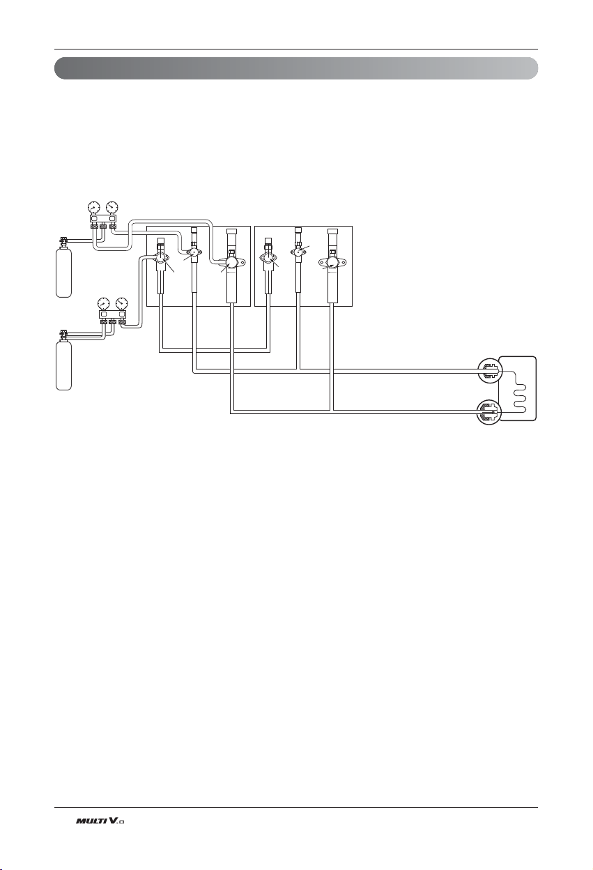
50 Outdoor Unit
Pipe connections between indoor and outdoor unit
Leak Test and Vacuum drying
Indoor unit
Nitrogen gas
cylinder
Nitrogen gas
cylinder
Slave 1 outdoor unit Master outdoor unit
High/low pressure
common pipe
Liquide pipe
Gas pipe
High/low pressure
common pipe
Liquide pipe
Gas pipe
Liquid side
Gas side
Close
Close
Close
Close
Close
Close
(1) Leak test
Leak test should be m
ade by pressurizing nitrogen gas to 3.8Mpa(551.1psi). If the pressure does not drop for 24
hours, the system passes the test. If the pressure drops, check where the nitrogen leaks. For the test method, refer
to the following figure. (Make a test with the service valves closed. Be also sure to pressurize liquid pipe, gas pipe
and high/low pressure common pipe)
The test result can be judged good if the pressure has not be reduced after leaving for about one day after completion
of nitrogen gas pressurization.
Note:
If the ambient temperature differs between the time when pressure is applied and when the pressure drop is
checked, apply the following correction factor
There is a pressure change of approximately 0.01Mpa(1.5psi) for each 1°C of temperature difference.
Correction= (Temp. at the time of pressurization – Temp. at the time of check) X 0.1
For example: Temperature at the time of pressurization 3.8MPa(551psi) is 27 °C
24 hour later: 3.73MPa(541psi), 20°C
In this case the pressure drop of 0.07MPa(10psi) is because of temperature drop
And hence there is no leakage in pipe occurred.
Caution:
To prevent the nitrogen from entering the refrigeration system in the liquid state, the top of the cylinder must be
at higher position than the bottom when you pressurize the system.
Usually the cylinder is used in a vertical standing position.

ENGLISH
Installation Manual 51
Pipe connections between indoor and outdoor unit
(2) Vacuum
Vacuum drying should be made from the service port provided on the outdoor unitʼs service valve to the vac-
uum pump commonly used for liquid pipe, gas pipe and high/low pressure common pipe. (Make Vacuum
from liquid pipe, gas pipe and high/low pressure common pipe with the service valve closed.)
* Never perform air purging using refrigerant.
• Vacuum drying: Use a vacuum pump that can evacuate to -100.7kPa(-14.6psi, 5Torr, -755mmHg).
1. Evacuate the system from the liquid and gas pipes with a vacuum pump for over 2 hrs and bring the sys-
tem to -100.7kPa(-14.6psi).
After maintaining system under that condition for over 1 hr, confirm the vacuum gauge rises. The system
may contain moisture or leak.
2. Following should be executed if there is a possibility of moisture remaining inside the pipe.
(Rainwater may enter the pipe during work in the rainy season or over a long period of time)
After evacuating the system for 2 hrs, give pressure to the system to 0.05MPa(7.3psi)(vacuum break) with
nitrogen gas and then evacuate it again with the vacuum pump for 1hr to -100.7kPa(-14.6psi)(vacuum dry-
ing). If the system cannot be evacuated to -100.7kPa(-14.6psi) within 2 hrs, repeat the steps of vacuum
break and its drying.
Finally, check if the vacuum gauge does not rise or not, after maintaining the system in vacuum for 1 hr.
WARNING
When Installing or moving the air conditioner to another site, recharge after perfect evacuation.
- If a different refrigerant or air is mixed with the original refrigerant, the refrigerant cycle may malfunction and
the unit may be damaged.
Scale
Use a graviometer. (One that can measure
down to 0.1kg(0.22lbs). If you are unable to
prepare such a high-precision gravimeter
you may use a charge cylinder.
Indoor unit
Slave 1 outdoor unit Master outdoor unit
High/low pressure
common pipe
Liquide pipe
Gas pipe
High/low pressure
common pipe
Liquide pipe
Gas pipe
Liquid side
Gas side
Close
Close
Close
Close
Close
Close
Vacuum
pump
Vacuum
pump
Note : Always add an appropriate amount of refrigerant. (For the refrigerant additional charge)
Too much or too little refrigerant will cause trouble.
To use the Vacuum Mode
(If the Vacuum mode is set, all valves of Indoor units and Outdoor units will be opened.)
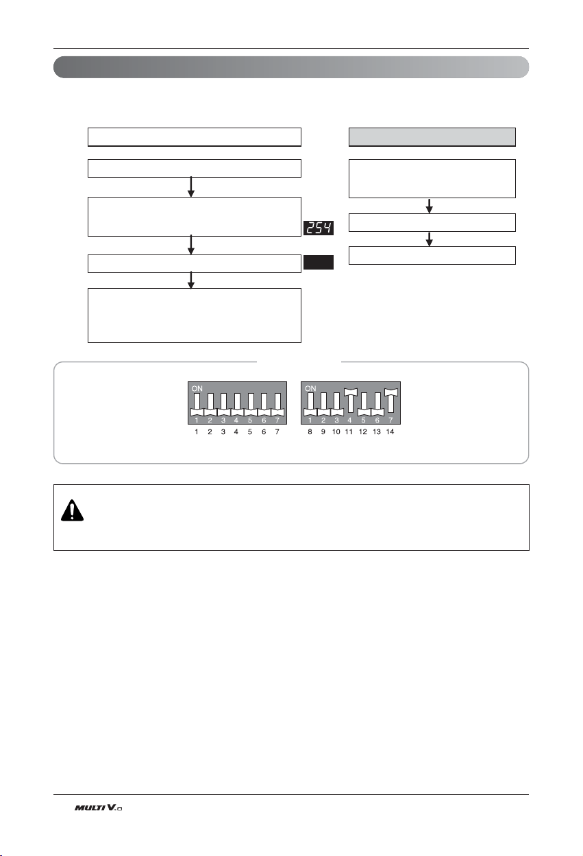
52 Outdoor Unit
Pipe connections between indoor and outdoor unit
Vacuum Mode
This function is used for creating vacuum in the system after compressor replacement, ODU parts replace-
ment or IDU addition/replacement.
Master unit PCB DIP switch on
- Heat pump : switch on 11, 14
- Cooling only : switch on 11, 14
Vacuum mode setting
ODU V/V OPEN
Main EEV, SC EEV OPEN
IDU EEV OPEN
ODU power reset
Press the black button Main PCB (5 sec.)
Vacuum mode setting method Vacuum mode cancellation method
Master unit PCB DIP switch off
- Heat pump : switch off 11, 14
- Cooling only : switch off 11, 14
Power reset
Vacuum mode cancellation
CAUTION
ODU operation stops during vacuum mode. Compressor can't operate.
DIP Switch Settings
Warning : Please reset Main PCB before starting this function
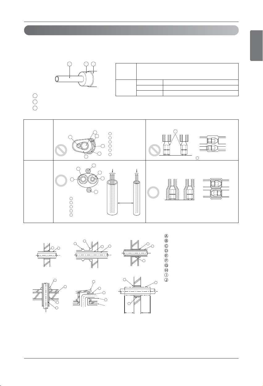
ENGLISH
Installation Manual 53
Pipe connections between indoor and outdoor unit
Thermal insulation of refrigerant piping
Heat
insulation
material
Outer
covering
Adhesive + Heat - resistant polyethylene foam +
Adhesive tape
Indoor Vinyl tape
Floor exposed
Water-proof hemp cloth + Bronze asphalt
Outdoor
Water-proof hemp cloth + Zinc plate + Oily paint
Note:
When using polyethylene cover as covering material, asphalt roof-
ing shall not be required.
• Do not insulate gas or low pressure pipe and liquid or high
pressure pipe together.
• Be sure to fully insulate connecting portion.
Liquid pipe
Gas pipe
Power lines
Finishing tape
Insulating material
Bad example
Good example
These parts are not insulated.
B A C
A
B
C
A
C
D
E
A
B
C
D
E
Transmission lines
F
Liquid pipe
Transmission lines
Transmission lines
Separation
Gas pipe
Power lines
Insulating material
A
B
C
D
E
A
A
B
F
Heat insulation material
Pipe
Outer covering
(Wind the connection part and cutting part of
heat insulation material with a finishing tape.)
Power lines
E
D
D
B
A
C
Be sure to give insulation work to refrigerant piping by covering liquid pipe and gas pipe separately with enough
thickness heat-resistant polyethylene, so that no gap is observed in the joint between indoor unit and insulating
material, and insulating materials themselves. When insulation work is insufficient, there is a possibility of con-
densation drip, etc. Pay special attention to insulation work to ceiling plenum.
1m1m
A
B
D
F
G
B
G
D
B
H
I
J
A
E
B
I
A
B
D
C
Inner wall (concealed)
Floor (fireproofing)
Penetrating portion on fire
limit and boundary wall
Roof pipe shaft
Outer wall Outer wall (exposed)
Penetrations
Sleeve
Heat insulating material
Lagging
Caulking material
Band
Waterproofing layer
Sleeve with edge
Lagging material
Mortar or other incombustible caulking
Incombustible heat insulation material
When filling a gap with mortar, cover the
penetration part with steel plate so that
the insulation material will not be caved in.
For this part, use incombustible materials
for both insulation and covering.(Vinyl
covering should not be used.)

54 Outdoor Unit
Electrical Wiring
Electrical Wiring
Caution
Remote
control
Remote
control
Remote
control
Remote
control
Indoor
Unit
Outdoor Unit
Outdoor Unit
Outdoor Unit
Outdoor Unit
Indoor
Unit
Remote
control
Remote
control
Indoor
Unit
Indoor
Unit
Remote
control
Remote
control
Indoor
Unit
Indoor
Unit
Indoor
Unit
Indoor
Unit
CAUTION
Be sure to correct the outdoor unit to earth. Do not connect earth line to any gas pipe, liquid pipe,
lightening rod or telephone earth line. If earth is incomplete, it may cause an electric shock.
WARNING
Be sure to have authorized electrical engineers do the electric work using special circuits in
accordance with regulations and this installation manual. If power supply circuit has a lack of
capacity or electric work deficiency, it may cause an electric shock or fire.
1. Follow ordinance of your governmental organization for technical standard related to electrical equipment, wiring
regulations and guidance of each electric power company.
2. Install the Outdoor Unit transmission line away from the power source wiring so that it is not affected by electric
noise from the power source. (Do not run it through the same conduit.)
3. Be sure to provide designated grounding work to Outdoor Unit.
4. Give some allowance to wiring for electrical part box of Indoor and Outdoor Units, because the box is sometimes
removed at the time of service work.
5. Never connect the main power source to terminal block of transmission line. If connected, electrical parts will
be burnt out.
6. Use 2-core shield cable for transmission line.(O mark in the figure below) If transmission lines of different sys-
tems are wired with the same multiplecore cable, the resultant poor transmitting and receiving will cause erro-
neous operations. ( mark in the figure below)
7. Only the transmission line specified should be connected to the terminal block for Outdoor Unit transmission.
2-Core Shield Cable Multi-Core Cable
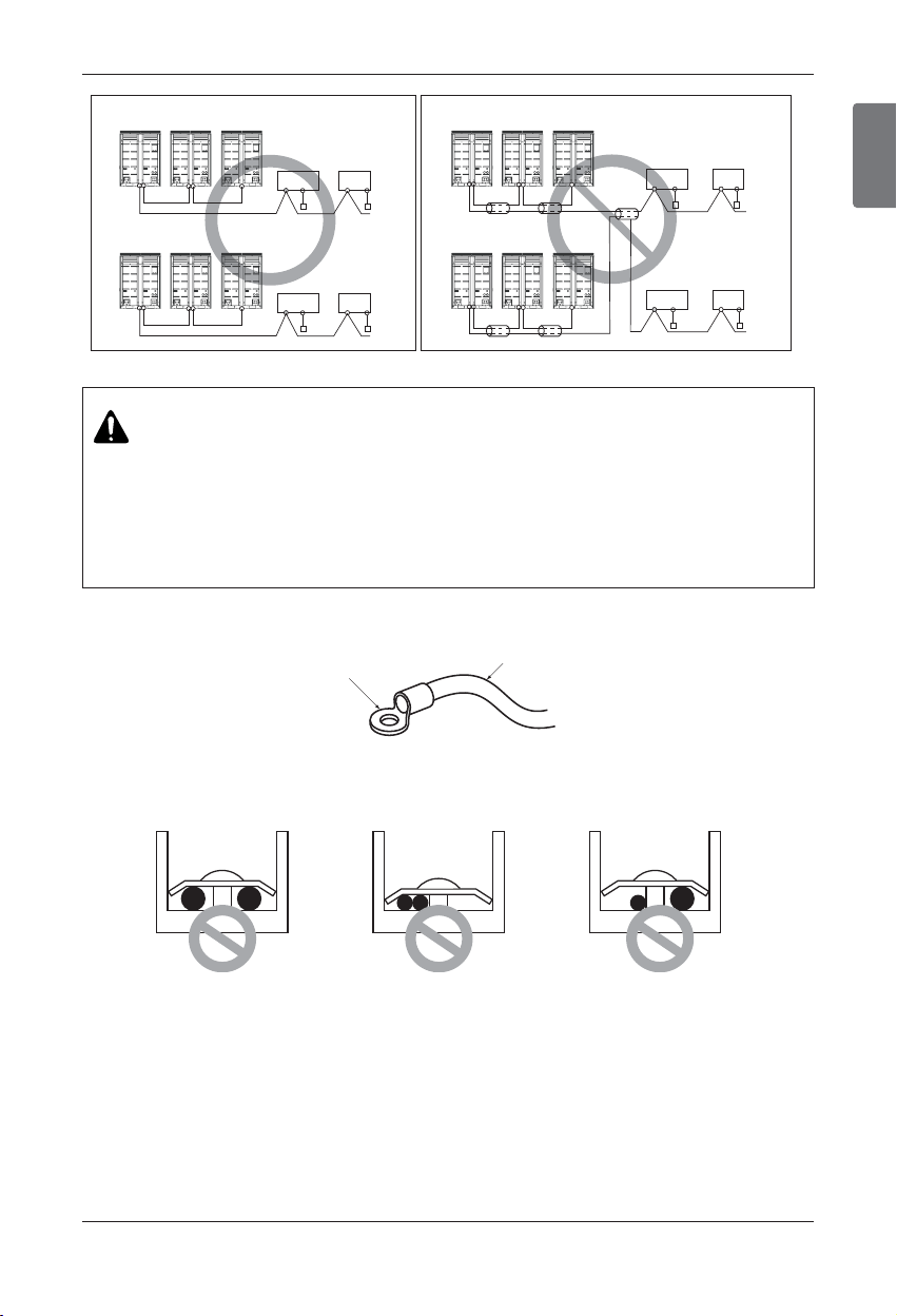
ENGLISH
Installation Manual 55
Electrical Wiring
Master Slave1 Slave2
Master Slave1 Slave2
Master Slave1 Slave2
Master Slave1 Slave2
Remote
controller
Remote
controller
Indoor
Unit
Indoor
Unit
Remote
controller
Outdoor Unit
Outdoor Unit
Outdoor Unit
Outdoor Unit
Remote
controller
Indoor
Unit
Indoor
Unit
Remote
controller
Remote
controller
Indoor
Unit
Indoor
Unit
Remote
controller
Remote
controller
Indoor
Unit
Indoor
Unit
2-Core Shield Cable Multi-Core Cable
CAUTION
• Use the 2-core shield cables for transmission lines. Never use them together with power cables.
• The conductive shielding layer of cable should be grounded to the metal part of both units.
• Never use multi-core cable
• As this unit is equipped with an inverter, to install a phase leading capacitor not only will deteriorate
power factor improvement effect, but also may cause capacitor abnormal heating. Therefore, never
install a phase leading capacitor.
• Make sure that the power unbalance ratio is not greater than 2%. If it is greater the units lifespan will
be reduced.
When none are available, follow the instructions below.
• Do not connect wiring of different thicknesses to the power terminal block. (Slack in the power wiring
may cause abnormal heat.)
• For wiring, use the designated power wire and connect firmly, then secure to prevent outside pressure
being exerted on the terminal block.
• Use an appropriate screwdriver for tightening the terinal screws. A screwdriver with a small head will
strip the head and make proper tighterning impossible.
• Over-tightening the terminal screws may break them.
u Precautions when laying power wiring
Round pressure terminal
Power wire
Use round pressure terminals for connections to the power terminal block.
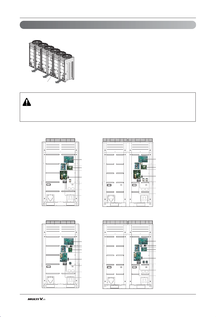
56 Outdoor Unit
Electrical Wiring
Control box and connecting position of wiring
- Remove all of the screws at front panel and remove the panel by pulling it forward.
- Connect transmission line between main and sub outdoor unit through the
terminal block.
- Connect transmission lines between outdoor unit and indoor units through
the terminal block.
- When the central control system is connected to the outdoor unit, a dedi-
cated PCB must be connected between them.
- When connecting transmission line between outdoor unit and indoor units
with shielded wire, connect the shield ground to the earth screw.
WARNING
The temperature sensor for outdoor air should not be exposed to direct sunlight.
- Provide an appropriate cover to intercept direct sunlight.
Front Panel
UX3
UX2
Main PCB
Fan PCB
Noise filter
Bridge diode
Magnet switch
Inverter PCB
Take care of the phase
sequence of 3-phase 3-wire
power system
Take care of the phase
sequence of 3-phase 3-wire
power system
Main PCB
Reactor
Fan PCB
Noise filter
Bridge diode
Magnet switch
Inverter PCB
Reactor
UX3
UX2
Main PCB
Fan PCB
Noise filter
Bridge diode
Magnet switch
Inverter PCB
Take care of the phase
sequence of 3-phase 3-wire
power system
Take care of the phase
sequence of 3-phase 3-wire
power system
Main PCB
Reactor
Fan PCB
Noise filter
Bridge diode
Magnet switch
Inverter PCB
Transformer
Reactor
Transformer
n 3Ø 208/230V
n 3Ø 460V
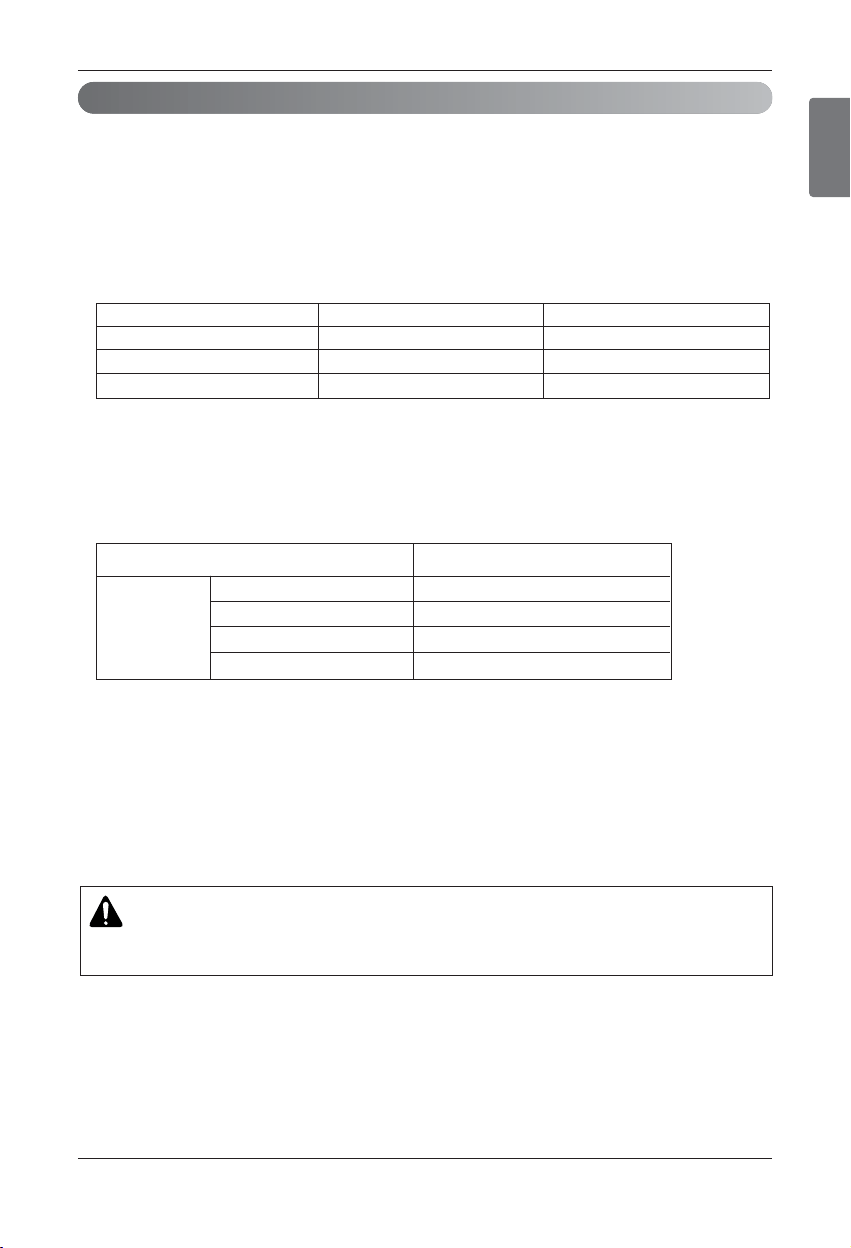
ENGLISH
Installation Manual 57
Electrical Wiring
Transmission and Power Lines
1) Communication cable
• Type : shielding wire
• Use wires of size : over 1.0~1.5mm
2
• Maximum allowable line length: under 1,000m(3,281ft)
2) Remote control cable
• Type : 3-core cable(shielding wire)
3) Central control cable
4) Separation of communication and power lines
• If communication and power lines are run alongside each other then there is a strong likelihood of
operational faults developing due to interference in the signal wiring caused by electrostatic and
electromagnetic coupling.
The tables below indicates our recommendation as to appropriate spacing of communication and power
lines where these are to be run side by side
Note:
1. The figures are based on assumed length of parallel cabling up to 100m(328ft). For length in excess of
100m(328ft) the figures will have to be recalculated in direct proportion to the additional length of line
involved.
2. If the power supply waveform continues to exhibit some distortion the recommended spacing in the table
should be increased.
• If the lines are laid inside conduits then the following point must also be taken into account when grouping
various lines together for introduction into the conduits
• Power lines(including power supply to air conditioner) and signal lines must not be laid inside the same
• In the same way, when grouping the lines power and signal lines should not be bunched together.
Current capacity of power line Spacing
10A 300m(11-13/16inch)
50A 500m(19-11/16inch)
100A 1,000m(39-3/8inch)
Exceed 100A 1,500m(59-1/16inch)
100V or more
CAUTION
n If apparatus is not properly earthed then there is always a risk of electric shocks, the earthing job of the
apparatus must be carried out by a qualified person.
Product type Wire type Diameter
ACP&AC Manager (2-shielding wire,2-core wire) 1.0~1.5mm
2
AC Smart (2-shielding wire,2-core wire) 1.0~1.5mm
2
Simple central controller (2-shielding wire,2-core wire) 1.0~1.5mm
2
58 Outdoor Unit
Wiring of main power supply and equipment capacity
Electrical Wiring
1. Use a separate power supply for the Outdoor Unit and Indoor Unit.
2. Bear in mind ambient conditions (ambient temperature,direct sunlight, rain water,etc.) when proceed-
ing with the wiring and connections.
3. The wire size is the minimum value for metal conduit wiring. The power cord size should be 1 rank
thicker taking into account the line voltage drops. Make sure the power-supply voltage does not drop
more than 10%.
4. Specific wiring requirements should adhere to the wiring regulations of the region.
5. Power supply cords of parts of appliances for outdoor use should not be lighter than polychloroprene
sheathed flexible cord.
6. Don't install an individual switch or electrical outlet to disconnect each of indoor unit separately from
the power supply.
WARNING
• Follow ordinance of your governmental organization for technical standard related to electrical equipment, wiring reg-
ulations and guidance of each electric power company.
• Make sure to use specified wires for connections so that no external force is imparted to terminal connections. If con-
nections are not fixed firmly, it may cause heating or fire.
• Make sure to use the appropriate type of overcurrent protection switch. Note that generated overcurrent may include
some amount of direct current.
CAUTION
•
Some installation site may require attachment of an earth leakage breaker. If no earth leakage breaker is installed, it may
cause an electric shock.
• Do not use anything other than breaker and fuse with correct capacity. Using fuse and wire or copper wire with too large ca-
pacity may cause a malfunction of unit or fire.
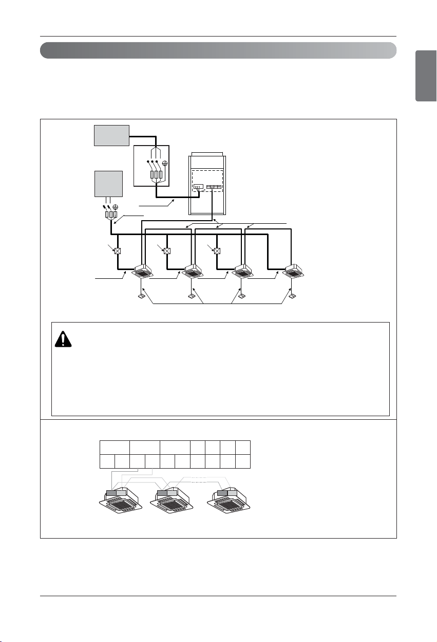
ENGLISH
Installation Manual 59
1. 60Hz
u Example Connection of Transmission Cable
n 1 Outdoor Unit - 3Ø, 208/230V
Power supply
1 Phase 60Hz
220~240V
L
N
Communication Line
(2 Wires Cable)
Power Line
(3 Wires Cable)
Communication Line
(3 Wires Cable)
Power Line
(2 Wires Cable)
Power Line
(2 Wires Cable)
Power Line
(2 Wires Cable)
Power Line
(2 Wires Cable)
Power Line
(2 Wires Cable)
[Outdoor Unit]
[Indoor Units]
Power supply
3 Phase 3 Wires
60Hz 208/230V
Power supply
1 Phase 60Hz
220~240V
(Main Switch)
Pull Box
(Installer option)
Pull Box
(Installer option)
Pull Box
(Installer option)
R S T
Switch
ELCB
ELCB
The GND terminal at the main PCB is a ‘-’ terminal for day contact, it is not the point to make
ground connection.
Between Indoor and Master Outdoor unit
[Heat Pump]
B
SODU IDU INTERNET DRY1 DRY2 GND 12V
AB
A
BA
Master
Outdoor Unit
34 34 34
WARNING
• Indoor Unit ground Lines are required for preventing electrical shock accident during current leakage,
Communication disorder by noise effect and motor current leakage (without connection to pipe).
• Don't install an individual switch or electrical outlet to disconnect each of indoor unit separately from the power supply.
• Install the main switch that can interrupt all the power sources in an integrated manner because this system consists of the
equipment utilizing the multiple power sources.
• If there exists the possibility of reversed phase, lose phase, momentary blackout or the power goes on and off while the prod-
uct is operating, attach a reversed phase protection circuit locally.
Running the product in reversed phase may break the compressor and other parts.
Electrical Wiring
Field Wiring(3Ø, 208/230V)
Note
1) Field Wiring diagram is to be used as a guidelineonly. Wiring should comply with applicable local and national codes
2) ELCB must have function to prevent electrical short and over current at the same time .
3) Use copper wires only.
4) Unit must be grounded in compliance with the applicable local and national codes.
5) ELCB and fuse/breaker must install to the power line
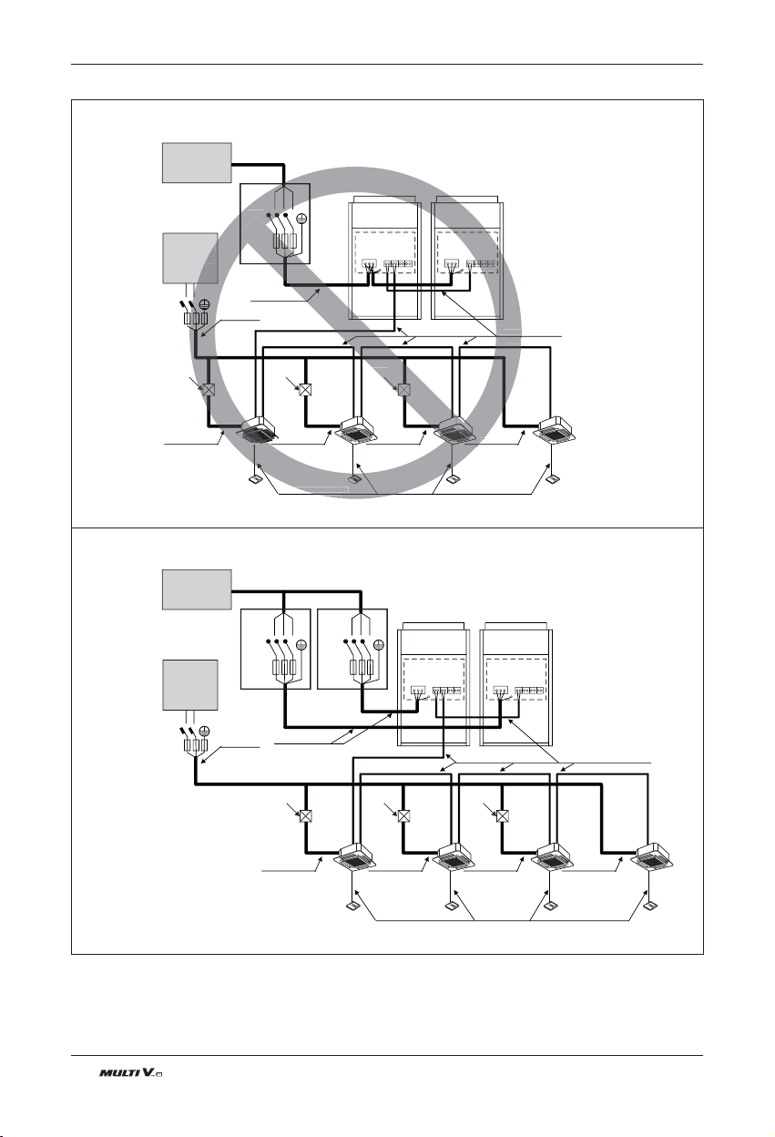
60 Outdoor Unit
■ Do not install the power source connected in series between the units.
■ Be sure that the power source is supplied to Each outdoor unit individually.
R S T
Switch
Communication Line
(2 Wires Cable)
Power Line
(3 Wires Cable)
Communication Line
(3 Wires Cable)
Power Line
(2 Wires Cable)
Power Line
(2 Wires Cable)
Power Line
(2 Wires Cable)
Power Line
(2 Wires Cable)
Power Line
(2 Wires Cable)
[Master]
[Indoor Units]
Power supply
3 Phase 3 Wires
60Hz 208/230V
Power Supply
1phase 60Hz
220~240V
(Main Switch)
[Slave]
Communication Line
(2 Wires Cable)
Power Line
(3 Wires Cable)
Communication Line
(3 Wires Cable)
Power Line
(2 Wires Cable)
Power Line
(2 Wires Cable)
Power Line
(2 Wires Cable)
Power Line
(2 Wires Cable)
Power Line
(2 Wires Cable)
[Master]
[Indoor Units]
Power supply
3 Phase 3 Wires
60Hz 208/230V
Power Supply
1phase 60Hz
220~240V
(Main Switch)
[Slave]
Pull Box
(Installer option)
Pull Box
(Installer option)
Pull Box
(Installer option)
Pull Box
(Installer option)
Pull Box
(Installer option)
Pull Box
(Installer option)
R
S
T
S
witch
Commu
(2 W
ommunication Line
Cable)
(2
Pow
(2 W
[M
aster
]
y
Hz
0V
ption)
Pull Box
aller option)
R S T
Switch
R S T
Switch
L
N
ELCB
ELCB
L
N
ELCB ELCB
ELCB
n 2 Outdoor Units - 3Ø, 208/230V
Electrical Wiring
Note
1) Field Wiring diagram is to be used as a guidelineonly. Wiring should comply with applicable local and national codes
2) ELCB must have function to prevent electrical short and over current at the same time .
3) Use copper wires only.
4) Unit must be grounded in compliance with the applicable local and national codes.
5) ELCB and fuse/breaker must install to the power line
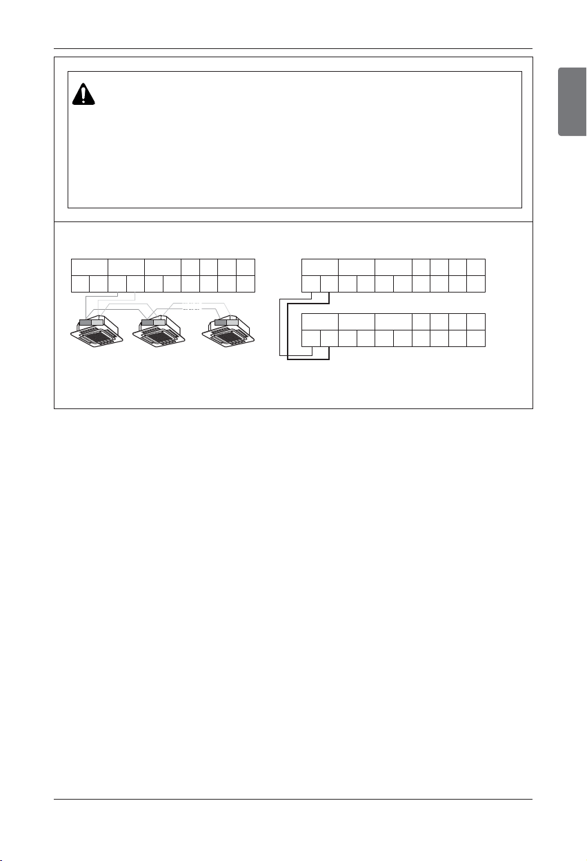
ENGLISH
Installation Manual 61
The GND terminal at the main PCB is a ‘-’ terminal for dry contact.
It is not the point to make ground connection.
• Make sure that terminal number of master and slave outdoor units are matched.(A-A,B-B)
[Heat Pump]
Between Indoor and Master Outdoor unit
B
SODU IDU INTERNET DRY1 DRY2 GND 12V
AB
A
BA
Master
Outdoor Unit
B
SODU IDU INTERNET DRY1 DRY2 GND 12V
AB
A
BA
Master
Outdoor Unit
B
SODU IDU INTERNET DRY1 DRY2 GND 12V
AB
A
BA
Slave
Outdoor Unit
34 34 34
WARNING
• Indoor Unit ground Lines are required for preventing electrical shock accident during current leakage,
Communication disorder by noise effect and motor current leakage (without connection to pipe).
• Don't install an individual switch or electrical outlet to disconnect each of indoor unit separately from the power supply.
• Install the main switch that can interrupt all the power sources in an integrated manner because this system consists of the
equipment utilizing the multiple power sources.
• If there exists the possibility of reversed phase, lose phase, momentary blackout or the power goes on and off while the prod-
uct is operating, attach a reversed phase protection circuit locally.
Running the product in reversed phase may break the compressor and other parts.
Electrical Wiring
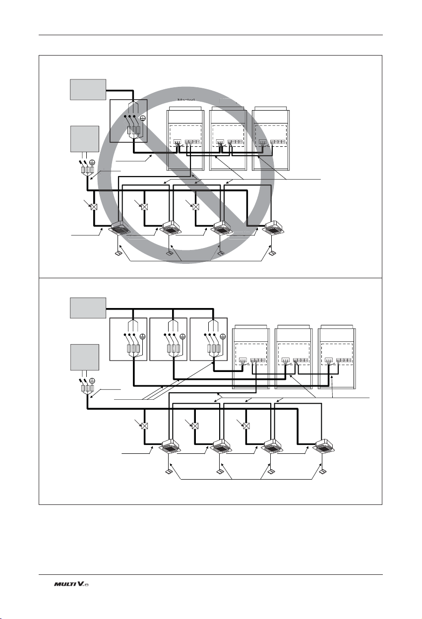
62 Outdoor Unit
L
N
ELCB
ELCB
L
N
ELCB ELCB ELCB
ELCB
■ Do not install the power source connected in series between the units.
■ Be sure that the power source is supplied to Each outdoor unit individually.
Communication Line
(2 Wires Cable)
Power Line
(3 Wires Cable)
Communication Line
(3 Wires Cable)
Power Line
(2 Wires Cable)
Power Line
(2 Wires Cable)
Power Line
(2 Wires Cable)
Power Line
(2 Wires Cable)
Power Line
(2 Wires Cable)
[Master]
[Indoor Units]
Power supply
3 Phase 3 Wires
60Hz 208/230V
Power supply
1 Phase 60Hz
220~240V
(Main Switch)
[Slave1] [Slave2]
Communication Line
(2 Wires Cable)
Power Line
(3 Wires Cable)
Communication Line
(3 Wires Cable)
Power Line
(2 Wires Cable)
Power Line
(2 Wires Cable)
Power Line
(2 Wires Cable)
Power Line
(2 Wires Cable)
Power Line
(2 Wires Cable)
[Master]
[Indoor Units]
Power supply
3 Phase 3 Wires
60Hz 208/230V
Power supply
1 Phase 60Hz
220~240V
(Main Switch)
[Slave1] [Slave2]
Pull Box
(Installer option)
Pull Box
(Installer option)
Pull Box
(Installer option)
Pull Box
(Installer option)
Pull Box
(Installer option)
Pull Box
(Installer option)
E
LCB
ation Line
Powe
(2 Wire
Powe
(2 Wires Ca
Power Line
(2 Wires Cable
[Master]
[Slave1]
Power L
res
R S T
Switch
R S T
Switch
R S T
Switch
R S T
Switch
n 3 Outdoor Units - 3Ø, 208/230V
Electrical Wiring
Note
1) Field Wiring diagram is to be used as a guidelineonly. Wiring should comply with applicable local and national codes
2) ELCB must have function to prevent electrical short and over current at the same time .
3) Use copper wires only.
4) Unit must be grounded in compliance with the applicable local and national codes.
5) ELCB and fuse/breaker must install to the power line
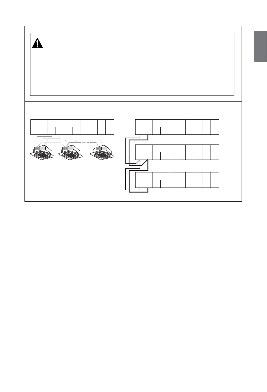
ENGLISH
Installation Manual 63
[Heat Pump]
Between Indoor and Master Outdoor unit
B
SODU IDU INTERNET DRY1 DRY2 GND 12V
AB
A
BA
Master
Outdoor Unit
B
SODU IDU INTERNET DRY1 DRY2 GND 12V
AB
A
BA
Master
Outdoor Unit
B
SODU IDU INTERNET DRY1 DRY2 GND 12V
AB
A
BA
Slave1
Outdoor Unit
B
SODU IDU INTERNET DRY1 DRY2 GND 12V
AB
A
BA
Slave2
Outdoor Unit
34 34 34
The GND terminal at the main PCB is a ‘-’
terminal for dry contact.
It is not the point to make ground
connection.
• Make sure that terminal number of master
and slave outdoor units are
matched.(A-A,B-B)
WARNING
• Indoor Unit ground Lines are required for preventing electrical shock accident during current leakage,
Communication disorder by noise effect and motor current leakage (without connection to pipe).
• Don't install an individual switch or electrical outlet to disconnect each of indoor unit separately from the power supply.
• Install the main switch that can interrupt all the power sources in an integrated manner because this system consists of the
equipment utilizing the multiple power sources.
• If there exists the possibility of reversed phase, lose phase, momentary blackout or the power goes on and off while the prod-
uct is operating, attach a reversed phase protection circuit locally.
Running the product in reversed phase may break the compressor and other parts.
Electrical Wiring
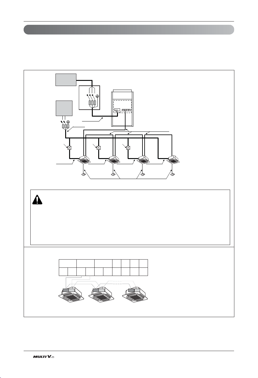
64 Outdoor Unit
L
N
Communication Line
(2 Wires Cable)
Power Line
(3 Wires Cable)
Communication Line
(3 Wires Cable)
Power Line
(2 Wires Cable)
Power Line
(2 Wires Cable)
Power Line
(2 Wires Cable)
Power Line
(2 Wires Cable)
Power Line
(2 Wires Cable)
[Outdoor Unit]
[Indoor Units]
Power supply
3 Phase 3 Wires
60Hz 460V
Power supply
1 Phase 60Hz
220~240V
(Main Switch)
Pull Box
(Installer option)
Pull Box
(Installer option)
Pull Box
(Installer option)
R S T
Switch
ELCB
ELCB
The GND terminal at the main PCB is a ‘-’ terminal for day contact, it is not the point to make
ground connection.
Between Indoor and Master Outdoor unit
[Heat Pump]
B
SODU IDU INTERNET DRY1 DRY2 GND 12V
AB
A
BA
Master
Outdoor Unit
34 34 34
WARNING
• Indoor Unit ground Lines are required for preventing electrical shock accident during current leakage,
Communication disorder by noise effect and motor current leakage (without connection to pipe).
• Don't install an individual switch or electrical outlet to disconnect each of indoor unit separately from the power supply.
• Install the main switch that can interrupt all the power sources in an integrated manner because this system consists of the
equipment utilizing the multiple power sources.
• If there exists the possibility of reversed phase, lose phase, momentary blackout or the power goes on and off while the
product is operating, attach a reversed phase protection circuit locally.
Running the product in reversed phase may break the compressor and other parts.
Field Wiring(3Ø, 460V)
Note
1) Field Wiring diagram is to be used as a guideline only. Wiring should comply with applicable local and national codes
2) ELCB must have function to prevent electrical short and over current at the same time .
3) Use copper wires only.
4) Unit must be grounded in compliance with the applicable local and national codes.
5) ELCB and fuse/breaker must install to the power line
1. 60Hz
u Example Connection of Communication Cable
n 1 Outdoor Unit - 3Ø, 460V
Electrical Wiring
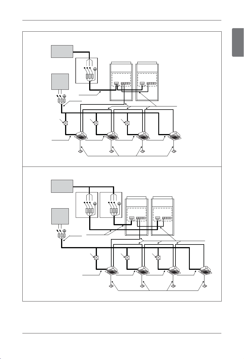
ENGLISH
Installation Manual 65
■ When the power source is connected in series between the units.
■ Be sure that the power source is supplied to Each outdoor unit individually.
R S T
Switch
Communication Line
(2 Wires Cable)
Power Line
(3 Wires Cable)
Communication Line
(3 Wires Cable)
Power Line
(2 Wires Cable)
Power Line
(2 Wires Cable)
Power Line
(2 Wires Cable)
Power Line
(2 Wires Cable)
Power Line
(2 Wires Cable)
[Master]
[Indoor Units]
Power Supply
3phase 3wires
60Hz 460V
Power Supply
1phase 60Hz
220~240V
(Main Switch)
[Slave]
Communication Line
(2 Wires Cable)
Power Line
(3 Wires Cable)
Communication Line
(3 Wires Cable)
Power Line
(2 Wires Cable)
Power Line
(2 Wires Cable)
Power Line
(2 Wires Cable)
Power Line
(2 Wires Cable)
Power Line
(2 Wires Cable)
[Master]
[Indoor Units]
Power Supply
3phase 3wires
60Hz 460V
Power Supply
1phase 60Hz
220~240V
(Main Switch)
[Slave]
Pull Box
(Installer option)
Pull Box
(Installer option)
Pull Box
(Installer option)
Pull Box
(Installer option)
Pull Box
(Installer option)
Pull Box
(Installer option)
R S T
Switch
R S T
Switch
L
N
ELCB
ELCB
L
N
ELCB ELCB
ELCB
n 2 Outdoor Units - 3Ø, 460V
Note
1) Field Wiring diagram is to be used as a guideline only. Wiring should comply with applicable local and national codes
2) ELCB must have function to prevent electrical short and over current at the same time .
3) Use copper wires only.
4) Unit must be grounded in compliance with the applicable local and national codes.
5) ELCB and fuse/breaker must install to the power line
Electrical Wiring
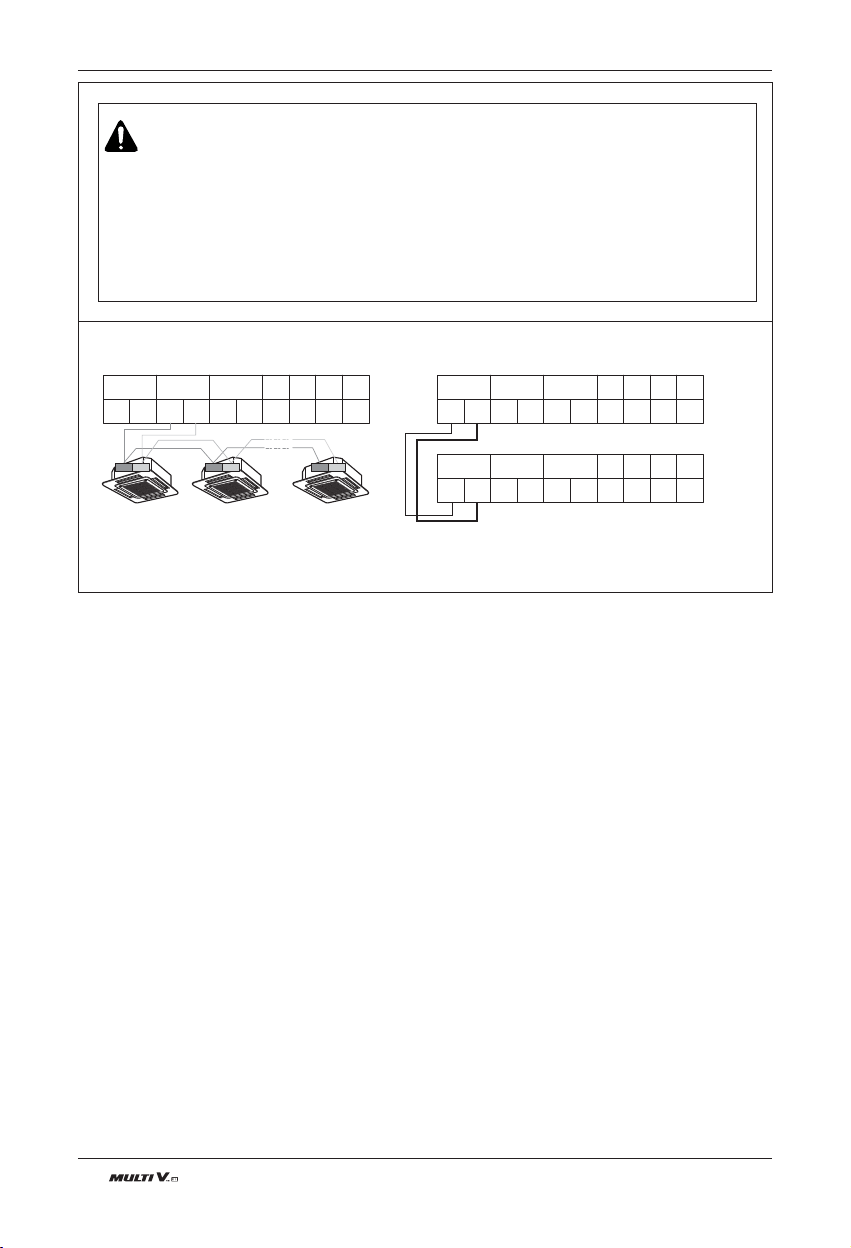
66 Outdoor Unit
The GND terminal at the main PCB is a ‘-’ terminal for dry contact.
It is not the point to make ground connection.
• Make sure that terminal number of master and slave outdoor units are matched.(A-A,B-B)
[Heat Pump]
Between Indoor and Master Outdoor unit
B
SODU IDU INTERNET DRY1 DRY2 GND 12V
AB
A
BA
Master
Outdoor Unit
B
SODU IDU INTERNET DRY1 DRY2 GND 12V
AB
A
BA
Master
Outdoor Unit
B
SODU IDU INTERNET DRY1 DRY2 GND 12V
AB
A
BA
Slave
Outdoor Unit
34 34 34
WARNING
• Indoor Unit ground Lines are required for preventing electrical shock accident during current leakage,
Communication disorder by noise effect and motor current leakage (without connection to pipe).
• Don't install an individual switch or electrical outlet to disconnect each of indoor unit separately from the power supply.
• Install the main switch that can interrupt all the power sources in an integrated manner because this system consists of the
equipment utilizing the multiple power sources.
• If there exists the possibility of reversed phase, lose phase, momentary blackout or the power goes on and off while the
product is operating, attach a reversed phase protection circuit locally.
Running the product in reversed phase may break the compressor and other parts.
Electrical Wiring
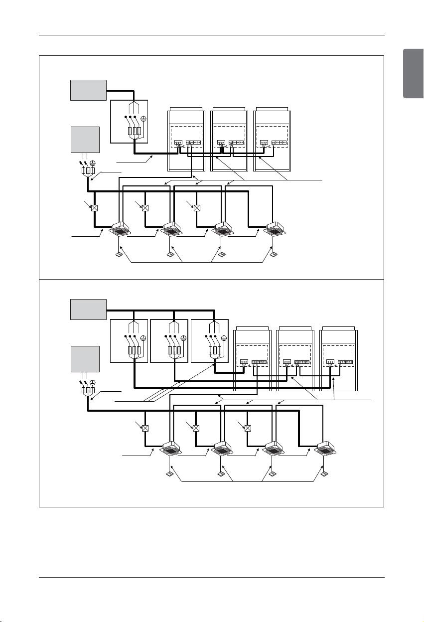
ENGLISH
Installation Manual 67
L
N
ELCB
ELCB
L
N
ELCB ELCB ELCB
ELCB
■ When the power source is connected in series between the units.
■ Be sure that the power source is supplied to Each outdoor unit individually.
Communication Line
(2 Wires Cable)
Power Line
(3 Wires Cable)
Communication Line
(3 Wires Cable)
Power Line
(2 Wires Cable)
Power Line
(2 Wires Cable)
Power Line
(2 Wires Cable)
Power Line
(2 Wires Cable)
Power Line
(2 Wires Cable)
[Master]
[Indoor Units]
Power supply
3 Phase 3 Wires
60Hz 460V
Power supply
1 Phase 60Hz
220~240V
(Main Switch)
[Slave1] [Slave2]
Communication Line
(2 Wires Cable)
Power Line
(3 Wires Cable)
Communication Line
(3 Wires Cable)
Power Line
(2 Wires Cable)
Power Line
(2 Wires Cable)
Power Line
(2 Wires Cable)
Power Line
(2 Wires Cable)
Power Line
(2 Wires Cable)
[Master]
[Indoor Units]
Power supply
3 Phase 3 Wires
60Hz 460V
Power supply
1 Phase 60Hz
220~240V
(Main Switch)
[Slave1] [Slave2]
Pull Box
(Installer option)
Pull Box
(Installer option)
Pull Box
(Installer option)
Pull Box
(Installer option)
Pull Box
(Installer option)
Pull Box
(Installer option)
R S T
Switch
R S T
Switch
R S T
Switch
R S T
Switch
n 3 Outdoor Units - 3Ø, 460V
Note
1) Field Wiring diagram is to be used as a guideline only. Wiring should comply with applicable local and national codes
2) ELCB must have function to prevent electrical short and over current at the same time .
3) Use copper wires only.
4) Unit must be grounded in compliance with the applicable local and national codes.
5) ELCB and fuse/breaker must install to the power line
Electrical Wiring
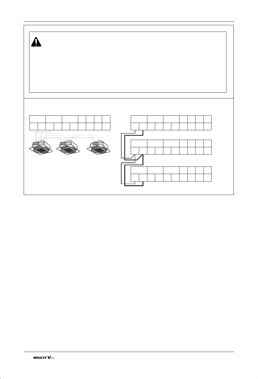
68 Outdoor Unit
[Heat Pump]
Between Indoor and Master Outdoor unit
B
SODU IDU INTERNET DRY1 DRY2 GND 12V
AB
A
BA
Master
Outdoor Unit
B
SODU IDU INTERNET DRY1 DRY2 GND 12V
AB
A
BA
Master
Outdoor Unit
B
SODU IDU INTERNET DRY1 DRY2 GND 12V
AB
A
BA
Slave1
Outdoor Unit
B
SODU IDU INTERNET DRY1 DRY2 GND 12V
AB
A
BA
Slave2
Outdoor Unit
34 34 34
The GND terminal at the main PCB is a ‘-’
terminal for dry contact.
It is not the point to make ground
connection.
• Make sure that terminal number of master
and slave outdoor units are
matched.(A-A,B-B)
WARNING
• Indoor Unit ground Lines are required for preventing electrical shock accident during current leakage,
Communication disorder by noise effect and motor current leakage (without connection to pipe).
• Don't install an individual switch or electrical outlet to disconnect each of indoor unit separately from the power supply.
• Install the main switch that can interrupt all the power sources in an integrated manner because this system consists of the
equipment utilizing the multiple power sources.
• If there exists the possibility of reversed phase, lose phase, momentary blackout or the power goes on and off while the
product is operating, attach a reversed phase protection circuit locally.
Running the product in reversed phase may break the compressor and other parts.
Electrical Wiring
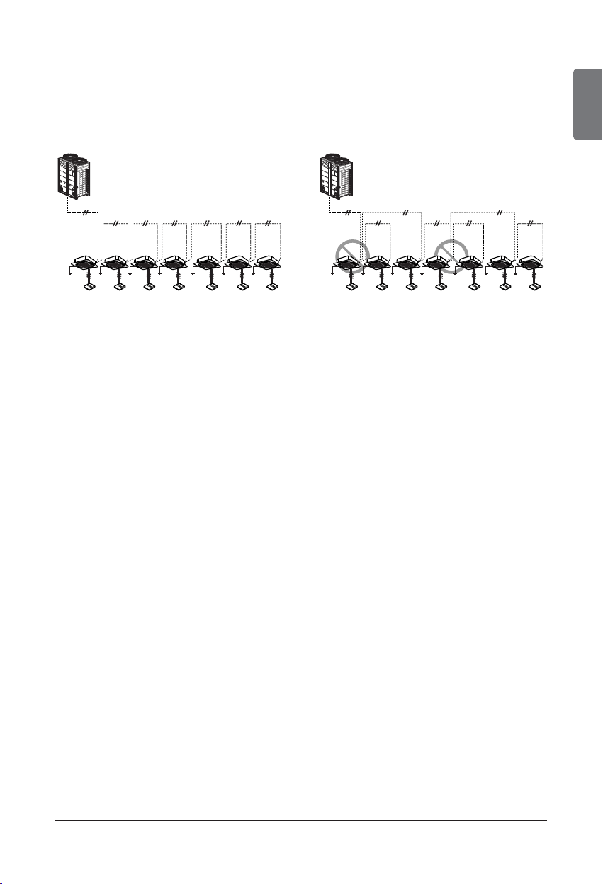
ENGLISH
Installation Manual 69
u Example Connection of Transmission Cable
[BUS type] [STAR type]
• Connection of transmission cable must be in-
stalled like below figure between indoor unit to
outdoor unit.
• Abnormal operation can be caused by communi-
cation defect, when connection of transmission
cable is installed like below figure(STAR type).
Electrical Wiring
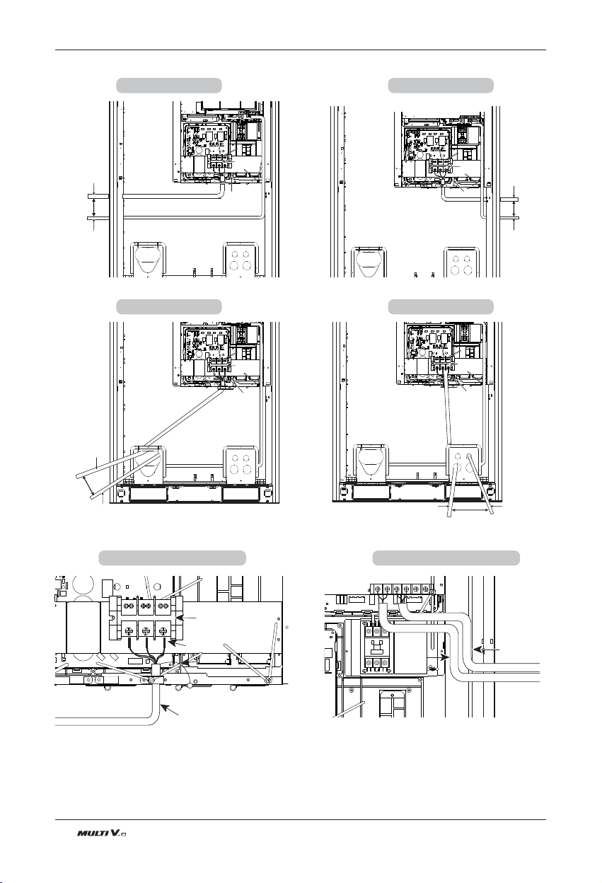
70 Outdoor Unit
u UX2 Chassis Wire Connection (3Ø, 208/230V)
Main Power
Terminal Block
Ground Cable
Power/Ground lines
Over 50mm Gap
Communication line
Main Power
Terminal Block
Left Side
Main Power
Terminal Block
Ground Cable
Communication line
Power/Ground lines
Over 50mm Gap
Main Power Main Power
Terminal BlockTerminal Block
Main Power
Terminal Block
Right Side
Ground Cable
Communication line
Power/Ground lines
Over
50mm Gap
Main Power Main Power
Terminal BlockTerminal Block
Main Power
Terminal Block
Front Side 1
Main Power
Terminal Block
Insulation sleeves attachments
Fix firmly not to be displaced
Ground Cable
Ground CableGround Cable
ODU-ODU
Communication line
ODU-IDU
Communication line
Ground Cable
ODU-ODU ODU-ODU
Communication lineCommunication line
ODU-ODU
Communication line
Communication line
Power/Ground lines
Over 50mm Gap
Main Power
Main Power
Terminal BlockTerminal Block
Main Power
Terminal Block
Ground Cable
Front Side 2
Main PCB ConnectionMain Power Connection
Electrical Wiring
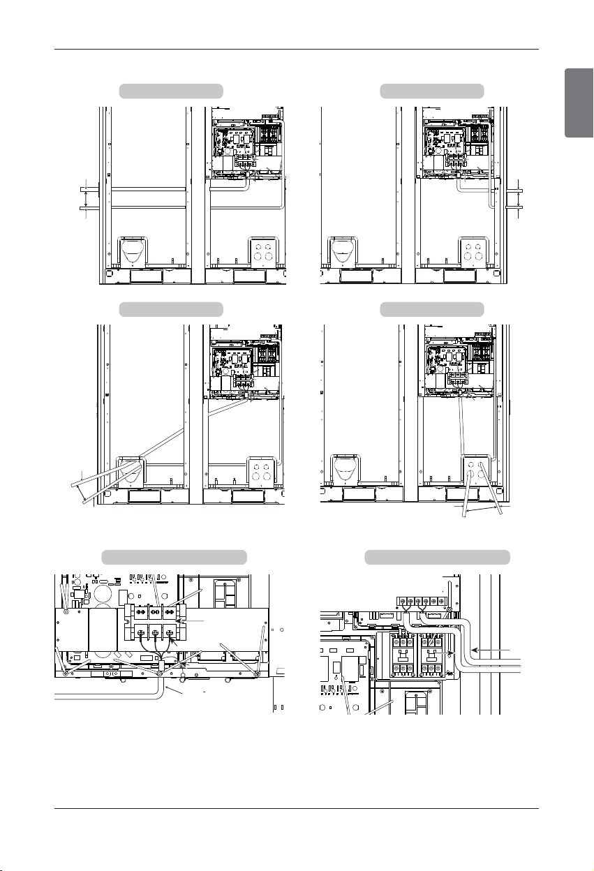
ENGLISH
Installation Manual 71
Electrical Wiring
Main Power Main Power
Terminal BlockTerminal Block
Main Power
Terminal Block
Ground Cable
Power/Ground lines
Over 50mm Gap
Communication line
Main Power
Terminal Block
Left Side
Main Power
Terminal Block
Main Power Main Power
Terminal BlockTerminal Block
Main Power
Terminal Block
Ground Cable
Power/Ground lines
Over 50mm Gap
Communication line
Right Side
Main Power Main Power
Terminal BlockTerminal Block
Main Power
Terminal Block
Ground Cable
Power/Ground lines
Over
50mm Gap
Communication line
Main Power
Terminal Block
Front Side 1
Insulation sleeves attachmentsInsulation sleeves attachmentsInsulation sleeves attachments
Ground Cable
Ground CableGround Cable
Fix firmly not
to be displaced
Main Power Terminal Block
Main Power Terminal BlockMain Power Terminal Block
ODU-ODU
Communication line
Insulation sleeves attachments
Ground Cable
Main Power Terminal Block
ODU-ODUODU-ODU
Communication lineCommunication line
ODU-ODU
Communication line
ODU-IDU
Communication
line
Main Power
Terminal Block
Main Power Main Power
Terminal BlockTerminal Block
Main Power
Terminal Block
Ground Cable
Power/Ground lines
Over 50mm Gap
Communication line
Front Side 2
Main PCB ConnectionMain Power Connection
u UX3 Chassis Wire Connection (3Ø, 208/230V)
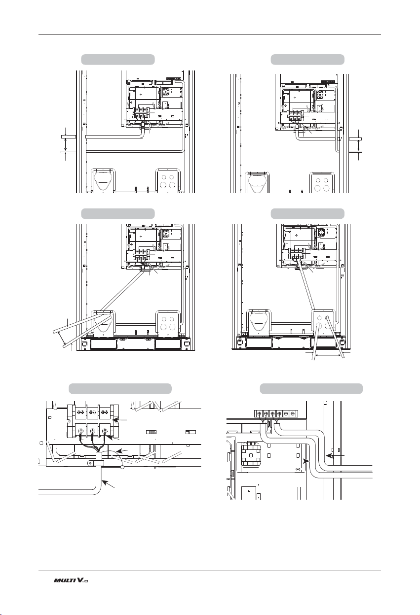
72 Outdoor Unit
u UX2 Chassis Wire Connection (3Ø, 460V)
Main Power Main Power
Terminal BlockTerminal Block
Main Power
Terminal Block
Ground Cable
Power/Ground lines
Over 50mm Gap
Communication line
Main Power
Terminal Block
Main Power
Terminal Block
Left Side
Ground Cable
Communication line
Power/Ground lines
Over 50mm Gap
Main Power
Terminal Block
Main Power Main Power
Terminal BlockTerminal Block
Main Power
Terminal Block
Main Power
Terminal Block
Right Side
Ground Cable
Communication line
Power/Ground lines
Over
50mm Gap
Main Power
Terminal Block
Main Power
Terminal Block
Main Power Main Power
Terminal BlockTerminal Block
Main Power
Terminal Block
Front Side 1
Main Power Main Power
Terminal BlockTerminal Block
Main Power
Terminal Block
Insulation sleeves attachments
Fix firmly not to be displaced
ODU-ODU
Communication line
Ground CableGround CableGround Cable
Main Power
Terminal Block
ODU-IDU
Communication line
ODU-ODU
ODU-ODU
Communication lineCommunication line
ODU-ODU
Communication line
Ground Cable
Communication line
Power/Ground lines
Over 50mm Gap
Main Power
Main Power
Terminal BlockTerminal Block
Main Power
Terminal Block
Ground Cable
Front Side 2
Main PCB ConnectionMain Power Connection
Electrical Wiring
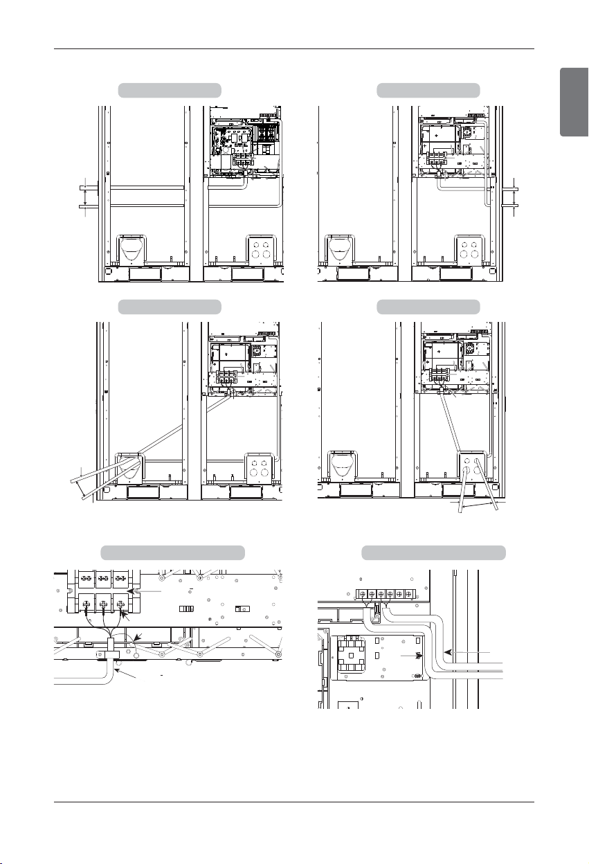
ENGLISH
Installation Manual 73
Electrical Wiring
u UX3 Chassis Wire Connection (3Ø, 460V)
Main Power Main Power
Terminal BlockTerminal Block
Main Power
Terminal Block
Ground Cable
Power/Ground lines
Over 50mm Gap
Communication line
Main Power
Terminal Block
Left Side
۾ڜ ɶۜʅ
Main Power
Terminal Block
Main Power Main Power
Terminal BlockTerminal Block
Main Power
Terminal Block
Ground Cable
Power/Ground lines
Over 50mm Gap
Communication line
Right Side
Main Power Main Power
Terminal BlockTerminal Block
Main Power
Terminal Block
Ground Cable
Power/Ground lines
Over
50mm Gap
Communication line
Main Power
Terminal Block
Front Side 1
:;<
Insulation sleeves attachments
Ground Cable
Fix firmly not
to be displaced
Main Power Terminal Block
Main Power Terminal BlockMain Power Terminal Block
ODU-ODU
Communication line
Main Power Terminal Block
ODU-ODUODU-ODU
Communication lineCommunication line
ODU-ODU
Communication line
ODU-IDU
Communication
line
Main Power
Terminal Block
Main Power Main Power
Terminal BlockTerminal Block
Main Power
Terminal Block
Ground Cable
Power/Ground lines
Over 50mm Gap
Communication line
Front Side 2
Main PCB ConnectionMain Power Connection
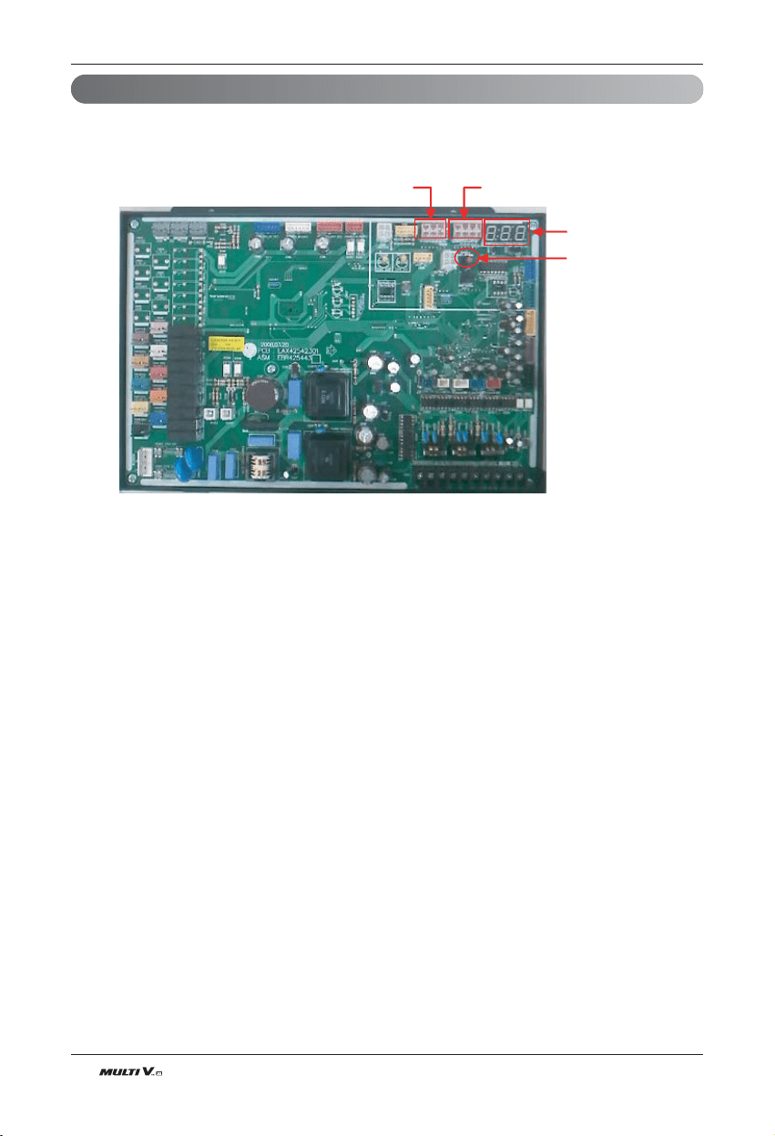
74 Outdoor Unit
Electrical Wiring
Location of setting dip switch
7 - Segment
SW02V
(Auto Addressing)
SW01B SW02B
n Heat Pump (Main PCB)
ENGLISH
Installation Manual 75
Electrical Wiring
DIP switch setting
n Checking according to dip switch setting
1. You can check the setting values of the Master outdoor unit from the 7 segment LED.
The dip switch setting should be changed when the power is OFF.
2. It checks whether the input is properly performed without the bad contact of the dip switch or not
n Checking the setting of the Master unit
The number is sequentially appeared at the 7 segment in 5 seconds after applying the power. This number
represents the setting condition. (For example, represents R410A 28HP)
Master model code ‘ Slave1 model code ‘ Slave2 model code ‘ total capacity ‘ 2 ‘ 25 ‘ 140 or 160
1 ~255 : Master model code
1 ~255 : Slave1 model code
1 ~255 : Slave2 model code
1 ~255 : Slave3 model code
8~42HP : HP number(sum of master capacity and slave capacity)
No display : cooling only 2 : heat pump
25 : normal
140 or 160 : Model Type (ARUN××BT3:140, ARUN××DT3:160)
Example) 28Hp, R410A
15 ’ 15 ’ 30 ’ 2 ’ 25 ’ 140 or 160
CAUTION
Product may not properly operate if the relevant DIP switch is not properly setup.
}
Refer to table code
Model Code
Model Code Unit (HP) Unit Ref.
12 8
13 10
14 12
15 14
Master &
Slave
R410A
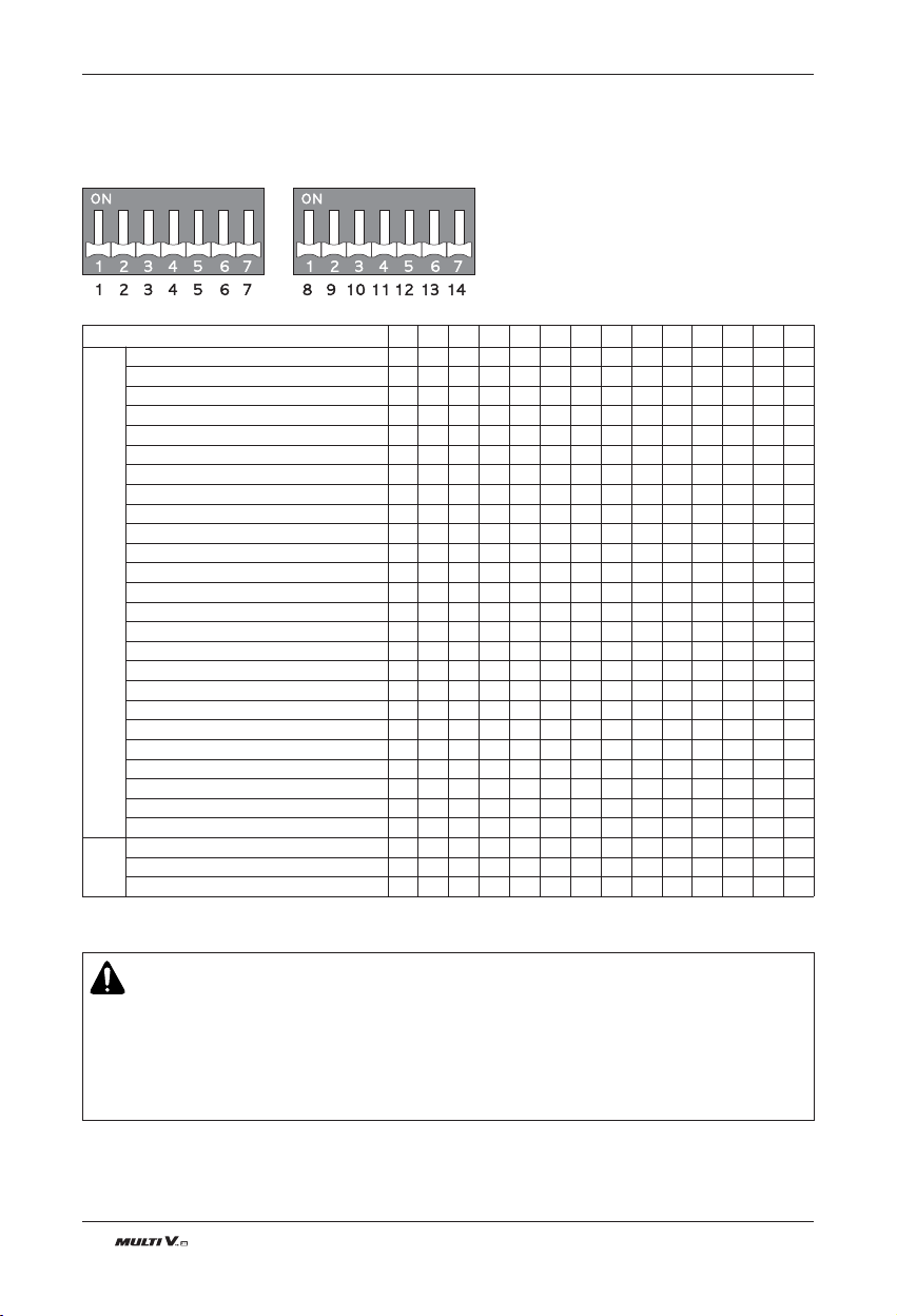
76 Outdoor Unit
Electrical Wiring
CAUTION
1. ʻXʼ mark within the table means that the dip switch must be pulled down. If not, the function may not work properly.
2. If the applicable dip switch is not set properly, the product may not work properly.
3. When executing the test operation, check the operating condition of the indoor unit and only execute the operation
when all indoor units are stopped.
4. Auto test operation function does not work for the product where only one indoor unit is connected for use.
5. Cooling Only model is not working on functions of Heat Pump model.
n Setting the DIP switch
• Heat pump
• If you set the Dip switch when power is on, the changed setting will not be applied immediately.
The changed setting will be enabled only when Power is reset or by pressing Reset button.
Index 1 2 3 4 5 6 7 8 9 10 11 12 13 14
Heating capacity up
●
IDU Fan RPM Control
●
Auto charging
● ● ● ⅹ ⅹ
Refrigerant Checking Function
● ● ● ⅹ ●
Integrated test operation function (Cooling)
● ● ⅹ ● ⅹ
Integrated test operation function (Heating)
● ● ⅹ ● ●
Inverter backup
●
Unit backup
●
Non-operation indoor unit EEV adjustment
ⅹ ⅹ ● ⅹ ⅹ
Indoor unit target subcooling/overheating adjustment
ⅹ ⅹ ⅹ ● ⅹ
Operation indoor unit EEV adjustment
ⅹ ● ● ⅹ ⅹ
Dry contact
● ● ⅹ
Snow removal fuction
● ⅹ
Forced defrost
ⅹ ●
Snow removal+Forced defrost
● ●
Forced overall defrost
● ●
Static pressure mode
ⅹ ⅹ ⅹ ● ⅹ
Nigh low noise operation (Cooling only)
● ⅹ ●
Night low noise operation (Cooling/Heating)
● ● ●
Pump down
● ⅹ
Pump out
● ●
Forced oil return operation
ⅹ ⅹ ● ⅹ
Vacuum mode
● ⅹ ⅹ ●
Selector Fan/ All OFF
ⅹ ⅹ ● ● ⅹ
ODU Address setting
● ⅹ ⅹ
Master unit
ⅹ ⅹ ⅹ
Slave 1 unit
● ⅹ ●
Slave 2 unit
ⅹ ● ●
Function
ODU
setting
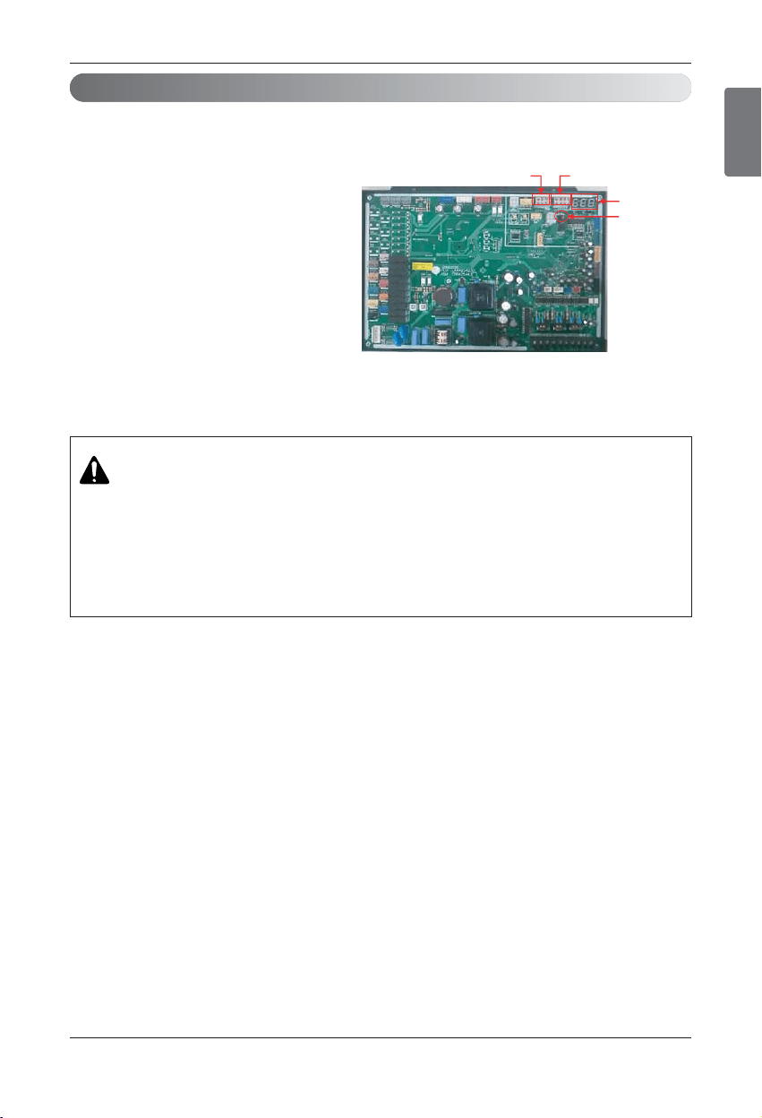
ENGLISH
Installation Manual 77
Electrical Wiring
Automatic Addressing
• The address of indoor units would be set by auto addressing
1) Wait for 3 minutes after supplying power.
(Master and Slave outdoor units, indoor units)
2) Press RED button of the outdoor units for 5
seconds. (H/P : SW02B)
3) A “88” is indicated on 7-segment LED of the
outdoor unit PCB.
4) For completing addressing, 2~7 minutes are
required depending on numbers of connected
indoor units
5) Numbers of connected indoor units whose ad-
dressing is completed are indicated for 30
seconds on 7-segment LED of the outdoor
unit PCB
6) After completing addressing, address of each
indoor unit is indicated on the wired remote
control display window. (CH00, CH01,
CH02, ……, CH06 : Indicated as number of
connected indoor units)
CAUTION
• In replacement of the indoor unit PCB, always perform Auto addressing setting
again (At that time, please check about using Independent power module to any
indoor unit.)
• If power supply is not applied to the indoor unit, operation error occur.
• Auto addressing is only possible on the master Unit.
• Auto addressing has to be performed after 3 minutes to improve communication.
7 - Segment
SW02V
(Auto Addressing)
SW01B SW02B
n Heat Pump (Main PCB)
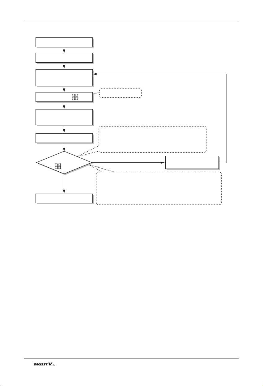
78 Outdoor Unit
Electrical Wiring
u The Procedure of Automatic Addressing
• Auto addressing setting end
Numbers of indoor unit connection set whose
addressing is completed are indicated for 30seconds
on 7-segment LED after completing setting
Indoor address number is displayed on wired remote control or
indoor unit display window. It is not an error message, will
disappeared when on/off button is pressed on remote control
ex) Display of 01, 02, ..., 15 means connection of 15 indoor
units and auto addressing is completed normally.
Auto addressing start
Waiting 3 minutes
Power On
Press RED Button for 5 sec.
(H/P : SW02V)
7-segment LED = 88
Don’t press RED Button
(H/P : SW02V)
Waiting about 2~7 minutes
7-segment LED
OK
YES
NO Check the connections
of transmission line
= 88
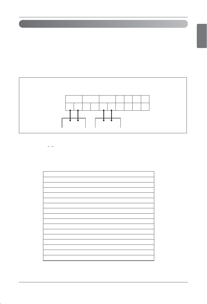
ENGLISH
Installation Manual 79
Electrical Wiring
Group Number setting
Group Number setting for Indoor Units
① Confirm the power of whole system(Indoor Unit, Outdoor Unit) is OFF, otherwise turn off.
② The transmission lines connected to INTERNET terminal should be connected to central control of Outdoor
Unti with care for their polarity( A ’ A, B ’ B )
③ Turn the whole system on.
④ Set the group and Indoor Unit number with a wired remote control.
⑤ To control several sets of Indoor Units into a group, set the group ID from 0 to F for this purpose.
Example) Group number setting
1
st
number indicate the group number
2
nd
number point out indoor unit number
[Heat Pump]
B(D) A(C) BA
B
SODU IDU INTERNET DRY1 DRY2 GND 12V
AB
A
BA
Group recognizing the simple central controller
No.0 group (00~0F)
No.1 group (10~1F)
No.2 group (20~2F)
No.3 group (30~3F)
No.4 group (40~4F)
No.5 group (50~5F)
No.6 group (60~6F)
No.7 group (70~7F)
No.8 group (80~8F)
No.9 group (90~9F)
No. A group (A0~AF)
No. B group (B0~BF)
No. C group (C0~CF)
No. D group (D0~DF)
No. E group (E0~EF)
No. F group (F0~FF)
Outdoor Units
1 F
Indoor unitGroup

80 Outdoor Unit
Electrical Wiring
Cool/Heat Selector Installation and Connection
Using Cool/Heat Selector Installation and Connection
- Connect wires to the cool/heat selector as shown in below figure
- Insert the wire in terminal by pushing “push” button
- Set the Dip SW of main PCB in master outdoor unit
¨≠
GNDGND
¨≠
GND
< Outdoor Main PCB >
- Insert wire method -
shows field wiring
connected wiring
Push arrow direction.
Insert wire to connector.
Push Button
<Outdoor Dry Contact Back Side >
¨
≠
¨
≠
GNDGNDGND
1
2
3
4
1
2
3
4
❈ Communication line length can be maximum 300m, use communication line as thick as 1.25mm
2
.
Without Cool/Heat Selector Installation and Connection
In case, try to set mode without Cool/Heat Selector and try to use other switch except from LG Outdoor
Cool/Heat Selector in field.
Connect signal terminal block as below figure and description.
- How to set mode without Cool/Heat Selector
• Cooling Mode Setting
¿‘GND Connection
¡‘Off (Open)
• Heating Mode Setting
¿‘ GND Connection
¡‘GND Connection
• Fan/ All OFF Mode Setting
¿‘ Off (Open)
¡‘GND Connection
GND
GND
GND
¨≠
GND
¨
≠
GND
ENGLISH
Installation Manual 81
Test Run
Test Run
1
2
3
4
Check to see whether there is any refrigerant leakage, and slack of power or transmission cable.
Confirm that 500 V megger shows 2 MΩ or more between power supply terminal block and ground. Do
not operate in the case of 2 MΩ or less.
NOTE: Never carry out megaohm check over terminal control board. Otherwise the control board
would be broken.
Immediately after mounting the unit or after leaving it turned off for an extended length of time,
the resistance of the insulation between the power supply terminal board and the ground may
decrease to approx. 2 MΩ as a result of refrigerant accumulating in the internal compressor.
If the insulation resistance is less than 2 MΩ, turning on the main power supply and energizing
the crankcase heater for more than 6 hours will cause the refrigerant to evaporate, increasing
the insulation resistance.
Check if high/low pressure common pipe, liquid pipe and gas pipe valves are fully opened.
NOTE: Be sure to tighten caps.
Check if there are any problems in automatic addressing or not:
Check and confirm that there are no error messages in the display of indoor units or remote controls
and LED in outdoor units.
Checks Before Test Run
CAUTION
when cutting main power of the Multi V
• Always apply main power of the outdoor unit during use of product
(cooling season/heating season).
• Always apply power 6 hours in advance to heat the crank case heater where performing test run
after installation of product. It may result in burning out of the compressor if not preheating the
crank case with the electrical heater for more than 6 hours.(In case of the outdoor temperatue
below 10°C)
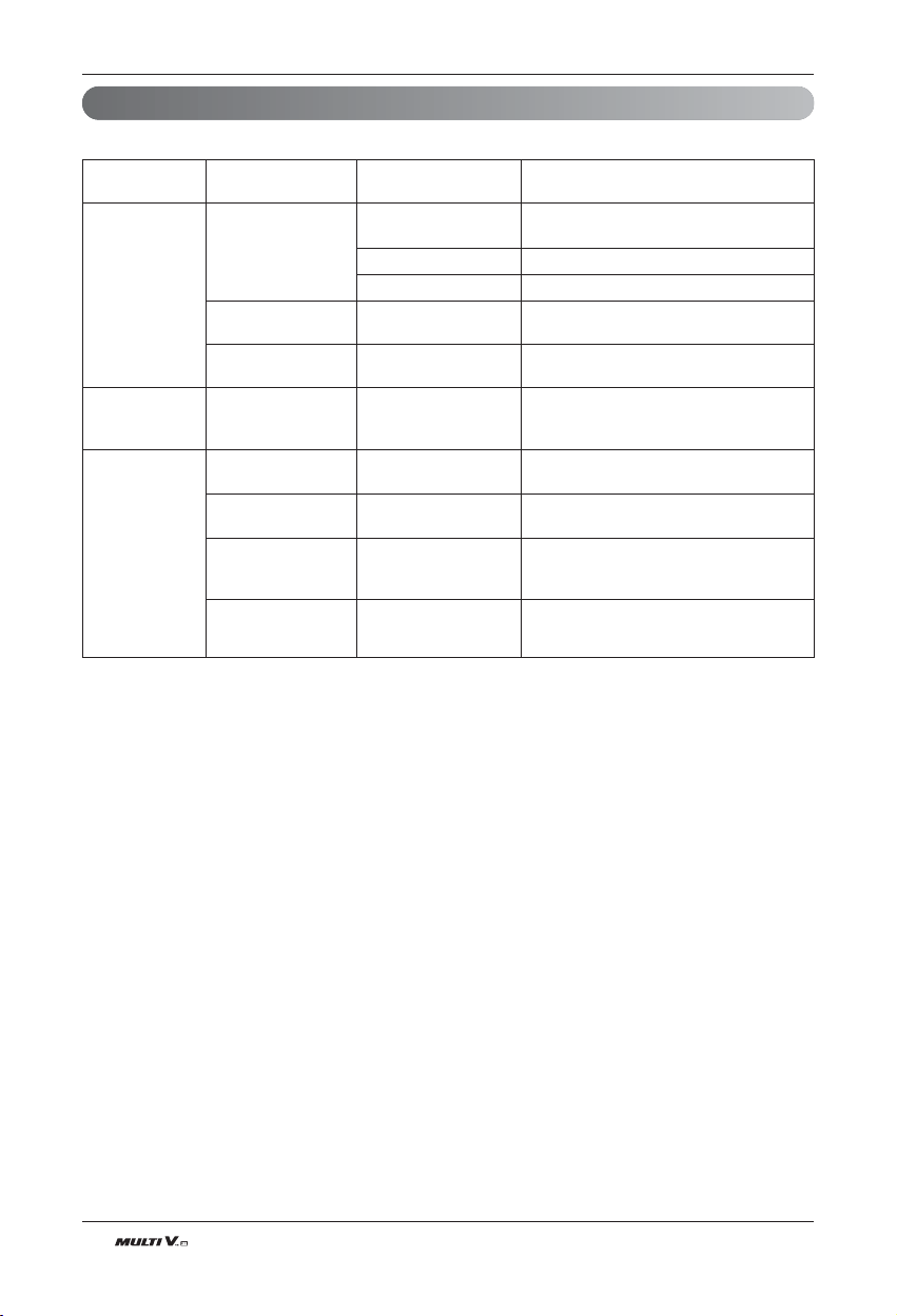
82 Outdoor Unit
Test Run
How to Cope with Test Run Abnormality
The phenomena from main component failure
Compressor
Outdoor
fan
Outdoor
EEV
Not operating
Stop during running
Abnormal noise
during running
High pressure error
at cooling
Heating failure, fre-
quent defrosting
No operating sound
at applying power
Heating failure,
frozen outdoor heat
exchanger part
Low pressure error
or discharge temper-
ature error
Motor insulation broken
Strainer clogged
Oil leakage
Motor insulation failure
R-S-T misconnection
Motor failure,
bad ventilation around
outdoor heat exchanger
Bad connector contact
Coil failure
EEV clogged
EEV clogged
Check resistance between terminals and
chassis
Change strainer
Check oil amount after opening oil port
Check resistance between terminals and
chassis
Check compressor R-S-T connection
Check the outdoor fan operation after being
turned the outdoor units off for some time.
Remove obstacles around the outdoor units
Check connector
Check resistance between terminals
Service necessary
Service necessary
Component Phenomenon Cause Check method and Trouble shooting
When system fault occurs, the error code is displayed at indoor unit display or remote control display,
the trouble shooting guide is in the service manual
Add Note : For detailed information, please refer Multi V Troubleshooting Guide Book

ENGLISH
Installation Manual 83
Test Run
Sensor checking function judges whether the current temperature of indoor and outdoor unit sensors is right or
not. 3 indoor temperature sensors, 10 outdoor temperature sensor Note 1), 2 outdoor pressure sensors.
Sensor Checking Function
Note 1. Outdoor Unit number of temperature sensors is different according to each chassis.
Note 2. Please check the sensor that is found abnormal.
Note 3. Each step is displayed on the Main PCB LED.
Note 4. Please refer to the sensor error descriptions on the next page.
@
Start
NO
NO
NO
YES
YES
3 minutes
past after power
reset
DIP switch set
Press black button
for 2 seconds
Sensor Normal
Display Error
Press black button for 2 seconds
Press black button for
5 seconds
End
Data Reset and Wait
All DIP switches OFF and press black
button for 2 seconds
Setting 1 Setting 2 Setting 3 Setting 4
Refrigerant
Auto Recharge
Refrigerant
Auto decide
E: Cooling
F: Heating
Start Inspection of each Function
Setting 1 Setting 2 Setting 3 Setting 4
Note 3)
DIP Switch Settings
Warning : Please reset before starting this function
- Setting1
(Refrigerant Auto Recharge)
- Setting2
(Refrigerant Quantity Auto Decide)
- Setting3
(Integrated Test Run - cooling)
- Setting4
(Integrated Test Run - heating)
WARNING
1. Please confirm if auto addressing function was executed. (Check the number of installed indoor units)
2. Error may occur when the sensor is abnormal according to the installed location and the temperature
conditions. When error occurs, please check each sensor and decide faultiness.
UX2(1 Comp) UX3 (2 Comp)
Heat Pump 6 7
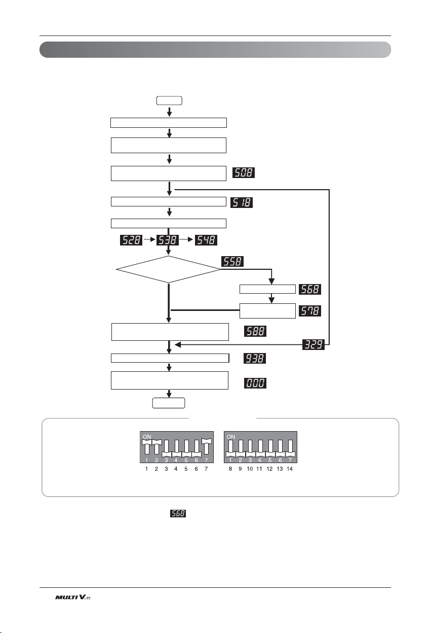
84 Outdoor Unit
Refrigerant Auto Charging
This function charges appropriate amount of refrigerant automatically through cycle operation.
It can be used when refrigerant amount Isn't certain because of SVC and leakage.
Wait for 3 min. after power reset
Start
Set the Dip S/W.
(Refer to DIP S/W setting)
Press the black button.
(Press until ‘508’ is displayed)
Press the black button.
Is it necessary to
charge refrigerant?
Press the black button for 2 sec. after turning off
all of dip S/W.
Yes
No
IDU runs with cooling mode In designated order.
Press the black button
IDU and ODU are turned off when Auto Charging
is completed. Close the valve.
Press the black button
*1)
Refrigerant Auto
Charging Process
Completed.
*2)
DIP Switch Settings
Warning : Please reset Main PCB before starting this function
Note
1. After installing the refrigerant charging device, as shown in figure, open the valve
2. In case air temperature is out of guaranteed temperature, it may end without performing Auto charging
3. Refrigerant charging Time may change according to the charging amount. (Abt. 1.5min/lbs)
Test Run
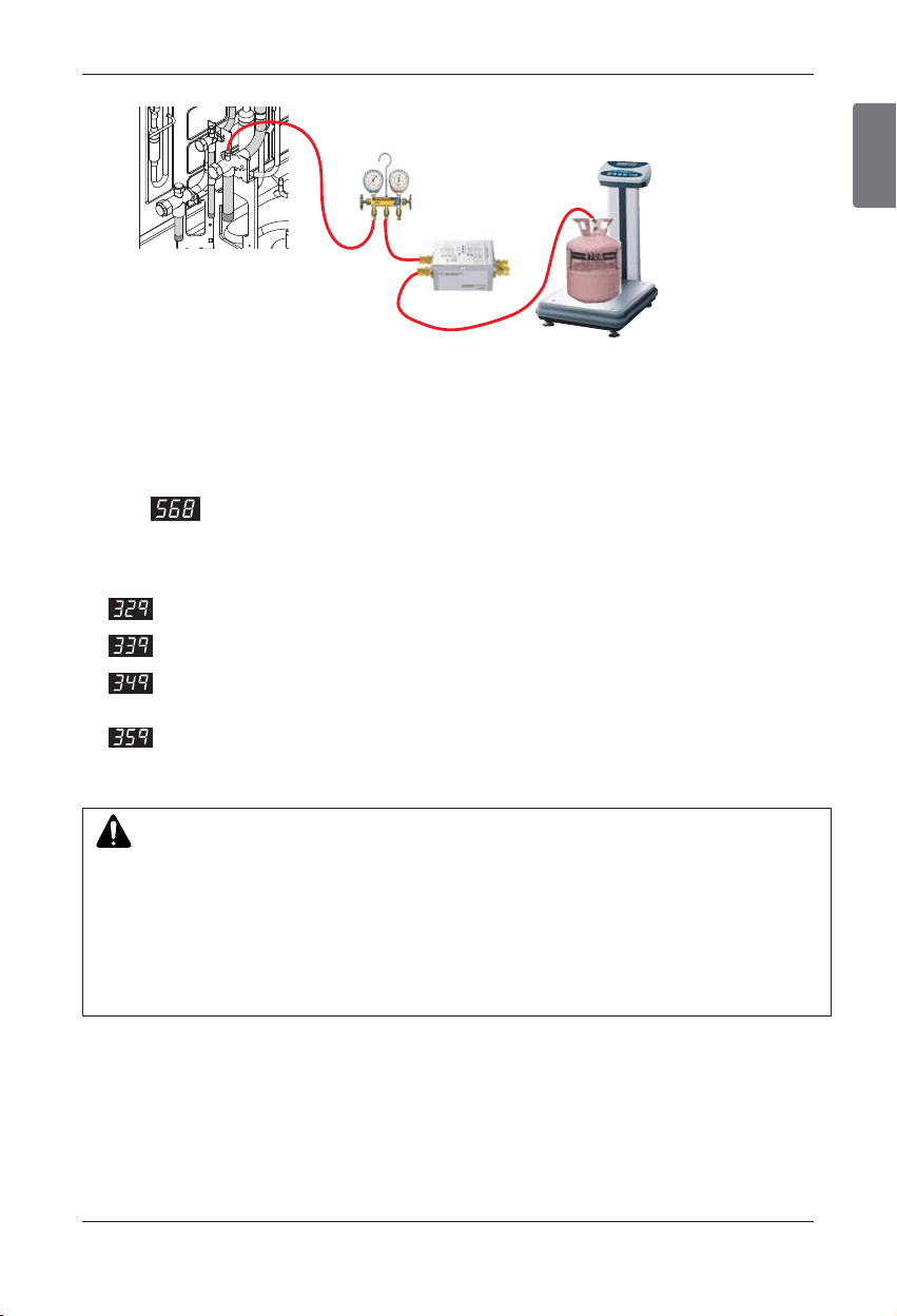
ENGLISH
Installation Manual 85
Test Run
Procedure
1. Arrange manifold,capillary assembly, refrigerant vessel and scale
2. Connect manifold to the gas pipe service valve of ODU as shown in the figure.
3. Connect manifold and Capillary tube.
Use designated capillary assembly only.
If designated capillary assembly isn't used, the system may get damaged.
4. Connect capillary and refrigerant vessel.
5. Purge hose and manifold.
6. After Is displayed, open the valve and charge the refrigerant
manifold
Capillary Assembly
Gas Pip
Gas Pipe
Liquid Pip
Liquid Pipe
Gas Pipe
Liquid Pipe
CAUTION
1. Guaranteed temperature range (Error will occur if temperature is out of range)
IDU : 20°C(68°F) ~ 32°C(90°F)
ODU : 0°C(32°F) ~ 43°C (109°F)
This temperature range is specifically for accurate refrigerant charging and is irrelative of opera-
tion temperature range
2. For refrigerant charging, use designated device only. (Capillary Assembly Set)
3. Set the IDU wired remote controller temperature sensing mode as IDU
4. Be careful that IDU should not be thermo off.
n Error contents about auto refrigerant charging function
1. : Temperature Range Error (In case that IDU or ODU is out of range)
2. : Low Pressure Descent Error (In case the system runs at low pressure limit for over 10 minutes)
3. : Judging rapid refrigerant inflow ( In case the liquid refrigerant flows in because of not using desig-
nated Capillary Assembly)
4. : Instability Error( In case the high/low pressure target doesn't get satisfied for some time
after the starting operation)
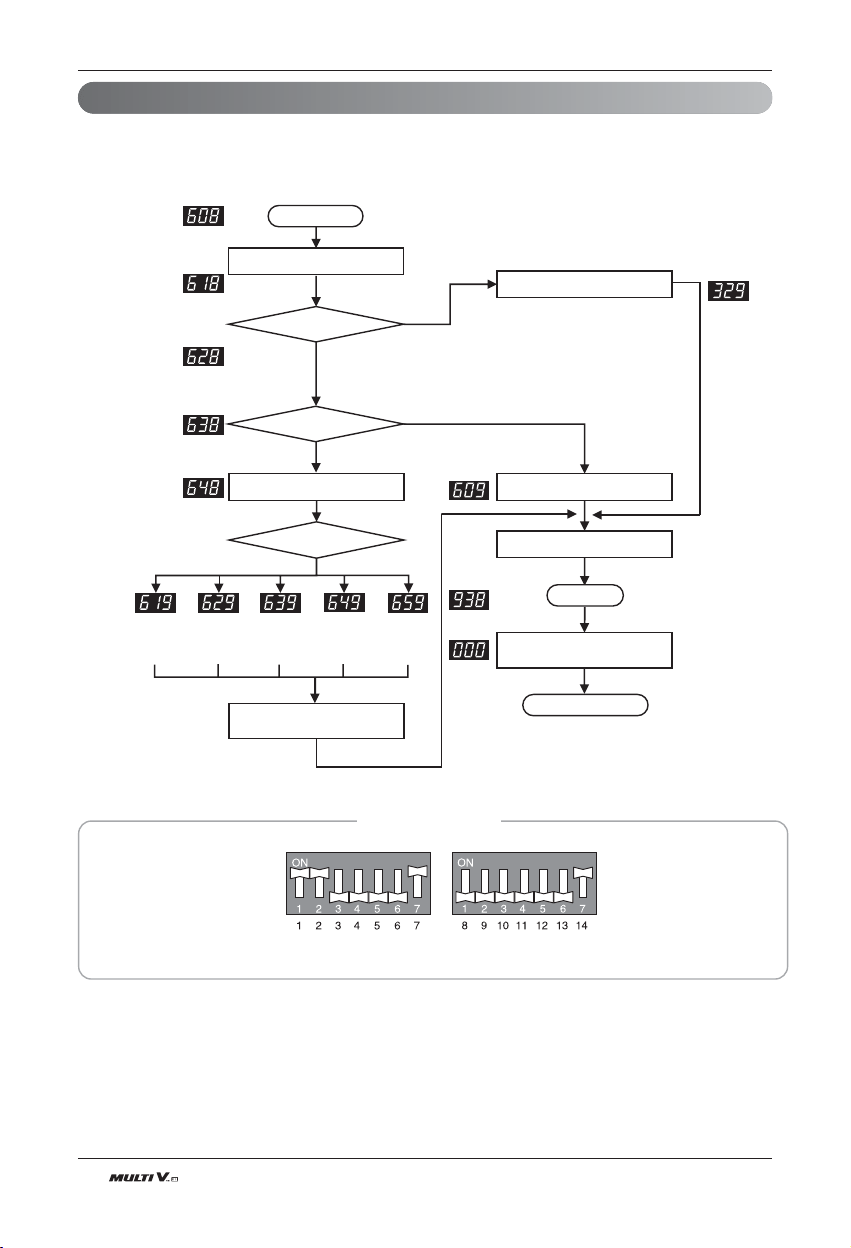
86 Outdoor Unit
Test Run
Refrigerant Checking Function
This function judges refrigerant leakage and overcharging
It can be used with refrigerant auto charging function.
Inspection Start
Press black button for 2 seconds
Proper Temperature
Thermo off indoor unit
Decide Refrigerant Quantity
Indoor Unit OFF
Too much
Refrigerant
Not enough
Refrigerant
Cannot tell
Quantity
Refrigerant
Quantity
Normal
Gas/Liquid
pipe direct
connection
Based on Refrigerant Quantity
NO
NO
YES
YES
Display Error
Display Error
Press black button for 2 seconds
Press black button for 2 seconds
Data Reset and Wait
End
Note
1. In case air temperature is out of guaranteed temperature, refrigerant checking function may end without performing refrigerant
checking. Use guaranteed temperature range only.
2. During the process of judging refrigerant amount, if the cycle isn't stable, refrigerant checking function may end without performing
refrigerant checking.
DIP Switch Settings
Warning : Please reset Main PCB before starting this function
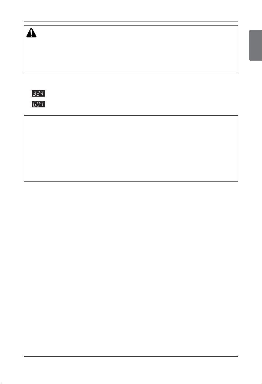
ENGLISH
Installation Manual 87
Test Run
[ Error contents about auto refrigerant charging function ]
1. : Temperature Range Error (In case that IDU or ODU is out of range)
2. : System Unstable Error (In case, After 45 min operating the system, it does not be stable)
How to Cope with Result of Refrigerant checking
1. If the temperature is not in guaranteed Temperature range, the system will not execute Refrigerant check-
ing and the system will be OFF.
2. Excess of Refrigerant(619)
After remove the 20% of calculated total refrigerant, recharge the refrigerant by using Refrigerant Auto
Charging Function.
3. Scarcity of Refrigerant(629)
Charge the refrigerant by using Refrigerant Auto Charging Function.
4. Impossible to Judge(639)
IF the system is not in order, check the other problem except refrigerant.
CAUTION
1. Guaranteed Temperature range(Error occurs out of guaranteed temperature range)
IDU : 20°C(68°F) ~ 32°C(90°F)
ODU : 0°C(32°F) ~ 43°C (109°F)
2. Set IDU wired remote controller temperature sensor setting as 'IDU'.
3. Make certain that IDU doesn't run with thermo off mode during operation.
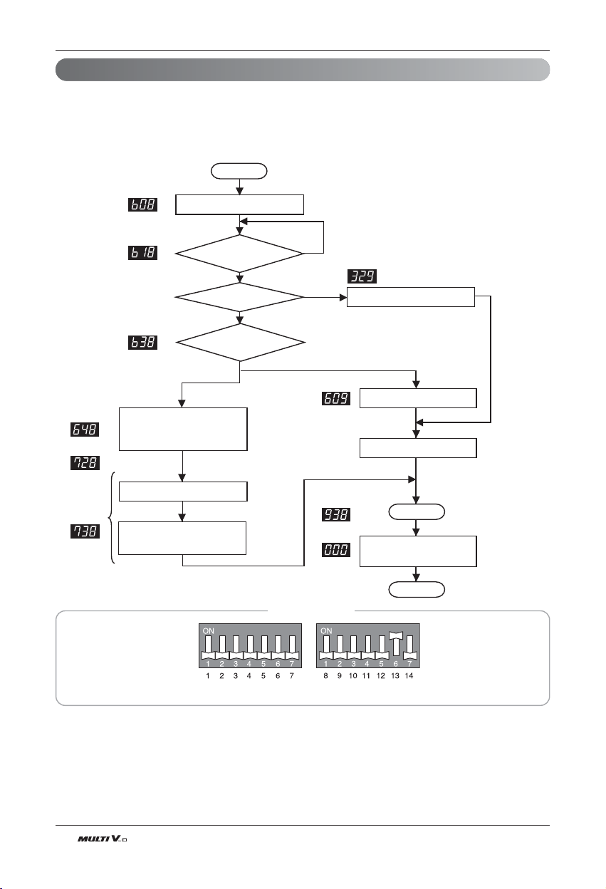
88 Outdoor Unit
Test Run
Integrated Test Running Function_Cooling Mode (Setting 3)
This function is checking process for normal operation of parts and system On operating system.
• All processes carry out included refrigerant amount judge logic and check normal condition of parts on cool-
ing mode.
• This function check only normal condition of parts on heating mode.
• Saved data can check using LGMV.
Note
1. Judge the normal condition refer to report of Test Running.
Thermo off
IDU judge
Start
Temp. Condition
1 IDU operation
1 IDU operation data
(10min)
Refrigerant amount judge
during all IDU operation
data on Test Runing(15min)
Error Display
Error Display
Press the black button for 2 sec
Yes
No
Note 1
End
Press the black button for 2 sec.
after turning off all of Dip switch.
Completed
Yes
All IDU operation on
Cooling mode
Press the black button for 2 sec
DIP Switch Settings
Warning : Please reset Main PCB before starting this function

ENGLISH
Installation Manual 89
Test Run
Integrated Test Running Function_Heating Mode (Setting 4)
This function is checking process for normal operation of parts and system On operating system.
• All processes carry out included refrigerant amount judge logic and check normal condition of parts on heating
mode.
• This function check only normal condition of parts on heating mode.
• Saved data can check using LGMV.
Start
Yes
No
Note 1
Note 1
Error Display
End
Completed
Press the black button for 2 sec.
after turning off all of Dip switch.
Error Display
1 IDU operation
1 IDU operation data(10min)
All IDU operation data(10min)
Temp. Condition
Press the black button for 2 sec.
Note
1. Judge the normal condition refer to report of Test Running.
DIP Switch Settings
Warning : Please reset Main PCB before starting this function
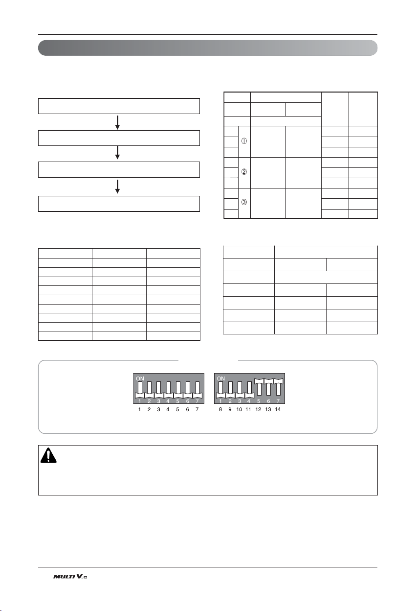
90 Outdoor Unit
Test Run
Night Silent Operation
In cooling mode, this function makes the ODU fan operate at low RPM to reduce the fan noise of ODU at night
which has low cooling load.
CAUTION
1. Request installer to set the function during installation.
2. In case the function is not used, set the dip S/W OFF and reset the power.
3. If ODU RPM changes, cooling capacity may go down.
RPM / Time Settings
1
2
8
6.5 10.5
9
512
9
8
6.5 10.5
512
9
8
6.5 10.5
12
5
620 780
680 800
900
Step
Capacity
(Hp)
Capacity
Fan Maximum RPM
Judgment
Time(Hr)
Operation
Time(Hr)
8
10~14
790
3
4
5
6
7
8
9
Reset the power
Setting the Fan Max. RPM
Note 1)
Setting Complete
Set the DIP S/W
DIP Switch Settings
Warning : Please reset Main PCB before starting this function
Step Black Button Red Button
1 1 time 1 time
2 2 time 1 time
3 3 time 1 time
4 4 time 1 time
5 5 time 1 time
6 6 time 1 time
7 7 time 1 time
8 8 time 1 time
9 9 time 1 time
Max. RPM setting method
Note 1)
Setting Method for Fan Max. RPM
Noise
Capacity
Capacity(HP) 8 10~14
Step Max. RPM Noise(dB)
Standard 58 62
①
55 59
②
52 56
③
49 53
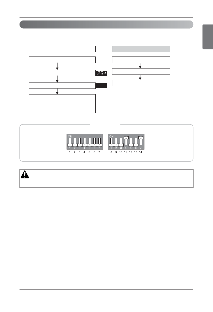
ENGLISH
Installation Manual 91
Test Run
This function is used for creating vacuum in the system after compressor replacement, ODU parts replace-
ment or IDU addition/replacement.
Vacuum Mode
Set the DIP S/W ON
Vacuum mode setting
ODU V/V OPEN
Main EEV, SC EEV OPEN
IDU EEV OPEN
ODU power reset
Press the black button Main PCB (5 sec.)
Vacuum mode setting method Vacuum mode cancellation method
Set the DIP S/W OFF
Power reset
Vacuum mode cancellation
CAUTION
ODU operation stops during vacuum mode.
DIP Switch Settings
Warning : Please reset Main PCB before starting this function

92 Outdoor Unit
Test Run
Static pressure compensation mode
This function secures the air flow rate of ODU, in case static pressure has been applied like using duct at fan
discharge of ODU.
n Static pressure compensation dip S/W setting method
High static pressure mode : Set DIP S/W
Note
How to set the unit to high ESP :
1) Standard ESP (External Static Pressure) : 4mmH
2
O (39.2Pa)
2) High ESP (External Static Pressure) : 8mmH
2
O (78.4Pa)
‘
The setting of dip S/W is needed. (Refer to above operating method)
Power Reset
Set the DIP S/W ON
Static pressure compensation mode setting
method
Static pressure compensation mode cancellation
method
DIP switch OFF
Power Reset
Static pressure compensation mode is set
Static pressure compensation mode is cancelled
DIP Switch Settings
Warning : Please reset Main PCB before starting this function
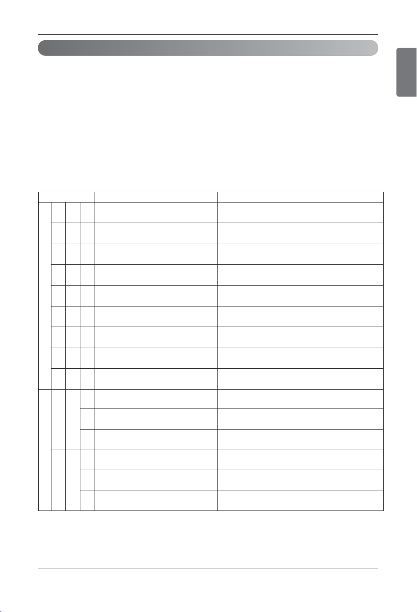
ENGLISH
Installation Manual 93
Test Run
Self-Diagnosis Function
Error Indicator
• This function indicates types of failure in self-diagnosis and occurrence of failure for air condition.
• Error mark is displayed on display window of indoor units and wired remote controller, and 7-segment LED of
outdoor unit control board as shown in the table.
• If more than two troubles occur simultaneously, lower number of error code is first displayed.
• After error occurrence, if error is released, error LED is also released simultaneously.
Error Display
1st,2nd LED of 7-segment indicates error number, 3rd LED indicates unit number.
Ex) 211 : No.21 error of master unit
213 : No.21 error of slave2
011 ’ 051 : No.105 error of master unit
Display Title Cause of Error
Indoor unit related error
0 1 - Air temperature sensor of indoor unit Air temperature sensor of indoor unit is open or short
0 2 - Inlet pipe temperature sensor of indoor unit Inlet pipe temperature sensor of indoor unit is open or short
0 3 -
Communication error : wired remote con-
troller ÷ indoor unit
Failing to receive wired remote controller signal in indoor
unit PCB
0 4 - Drain pump Malfunction of drain pump
0 5 -
Communication error : outdoor unit ÷ in-
door unit
Failing to receive outdoor unit signal in indoor unit PCB
0 6 -
Outlet pipe temperature sensor of indoor
unit
Outlet pipe temperature sensor of indoor unit is open or
short
0 9 - Indoor EEPROM Error
In case when the serial number marked on EEPROM of In-
door unit is 0 or FFFFFF
1 0 - Poor fan motor operation
Disconnecting the fan motor connector/Failure of indoor
fan motor lock
1 7 - Inlet Air temperature sensor of FAU Air temperature sensor of indoor unit is open or short
Outdoor unit related error
2 1
1
Master Outdoor Unit Inverter Compressor
IPM Fault
Master Outdoor Unit Inverter Compressor Drive IPM Fault
2
Slave1 Outdoor Unit Inverter Compressor
IPM Fault
Slave1 Outdoor Unit Inverter Compressor Drive IPM Fault
3
Slave2 Outdoor Unit Inverter Compressor
IPM Fault
Slave2 Outdoor Unit Inverter Compressor Drive IPM Fault
2 2
1
Inverter Board Input Over Current(RMS) of
Master Outdoor Unit
Master Outdoor Unit Inverter Board Input Current excess
(RMS)
2
Inverter Board Input Over Current(RMS) of
Slave1 Outdoor Unit
Slave1 Outdoor Unit Inverter Board Input Current excess
(RMS)
3
Inverter Board Input Over Current(RMS) of
Slave2 Outdoor Unit
Slave2 Outdoor Unit Inverter Board Input Current excess
(RMS)
h Refer to the DX-Venitilation manual for DX-Venitilation error code
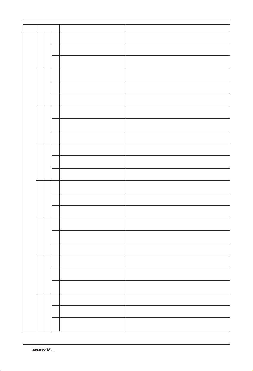
94 Outdoor Unit
Test Run
DC charging is not performed at Master Outdoor Unit
after starting relay turn on.
DC charging is not performed at Slave1 Outdoor Unit
after starting relay turn on.
DC charging is not performed at Slave2 Outdoor Unit
after starting relay turn on.
System is turned off by Master Outdoor Unit high pres-
sure switch.
System is turned off by slave1 Outdoor Unit high pres-
sure switch.
System is turned off by slave2 Outdoor Unit high pres-
sure switch.
Master Outdoor Unit(208/230V) input voltage is over 300V or below 140V
Master Outdoor Unit(460V) input voltage is over 487V or below 270V
Slave1 Outdoor Unit(208/230V) input voltage is over 300V or below 140V
Slave1 Outdoor Unit(460V) input voltage is over 487V or below 270V
Slave2 Outdoor Unit(208/230V) input voltage is over 300V or below 140V
Slave2 Outdoor Unit(460V) input voltage is over 487V or below 270V
The First Start Failure by Master Outdoor Unit Inverter
Compressor Abnormality
The First Start Failure by Slave1 Outdoor Unit Inverter
Compressor Abnormality
The First Start Failure by Slave2 Outdoor Unit Inverter
Compressor Abnormality
System is turned off by Master Outdoor Unit DC Volt-
age Over Charging
System is turned off by Slave1 Outdoor Unit DC Volt-
age Over Charging
System is turned off by Slave2 Outdoor Unit DC Volt-
age Over Charging
Master Outdoor Unit Inverter Compressor Fault OR
Drive Fault
Slave1 Outdoor Unit Inverter Compressor Fault OR
Drive Fault
Slave2 Outdoor Unit Inverter Compressor Fault OR
Drive Fault
Master Outdoor Unit Inverter Com-
pressor DC link Low Voltage
Slave1 Outdoor Unit Inverter Com-
pressor DC link Low Voltage
Slave2 Outdoor Unit Inverter Com-
pressor DC link Low Voltage
Master Outdoor Unit High Pres-
sure Switch
Slave1 Outdoor Unit High Pres-
sure Switch
Slave2 Outdoor Unit High Pres-
sure Switch
Master Outdoor Unit Input Voltage
High/ Low Voltage
Slave1 Outdoor Unit Input Voltage
High/ Low Voltage
Slave2 Outdoor Unit Input Voltage
High/ Low Voltage
Master Outdoor Unit Inverter Com-
pressor Start Failure
Slave1 Outdoor Unit Inverter Com-
pressor Start Failure
Slave2 Outdoor Unit Inverter Com-
pressor Start Failure
Master Outdoor Unit Inverter DC
link High Voltage
Slave1 Outdoor Unit Inverter DC
link High Voltage
Slave2 Outdoor Unit Inverter DC
link High Voltage
Master Outdoor Unit Inverter Com-
pressor Over Current
Slave1 Outdoor Unit Inverter Com-
pressor Over Current
Slave2 Outdoor Unit Inverter Com-
pressor Over Current
Display Title Cause of Error
1
2 3 2
3
1
2 4 2
3
1
2 5 2
3
1
2 6 2
3
1
2 8 2
3
1
2 9 2
3
Outdoor unit related error
System is turned off by Master Outdoor Uunit Constant Speed Com-
pressor2 High Discharge Temperature
System is turned off by Slave1 Outdoor Unit Constant Speed Com-
pressor2 High Discharge Temperature
System is turned off by Slave2 Outdoor Unit Constant Speed Com-
pressor2 High Discharge Temperature
System is turned off by Master Outdoor Unit Inverter Compressor
High Discharge Temperature
System is turned off by Slave1 Outdoor Unit Inverter Compressor
High Discharge Temperature
System is turned off by Slave2 Outdoor Unit Inverter Compressor
High Discharge Temperature
Master Outdoor Unit Constant Speed Com-
pressor2 High Discharge Temperature
Slave1 Outdoor Unit Constant Speed Com-
pressor2 High Discharge Temperature
Slave2 Outdoor Unit Constant Speed Com-
pressor2 High Discharge Temperature
Master Outdoor Unit Inverter Compressor
High Discharge Temperature
Slave1 Outdoor Unit Inverter Compressor
High Discharge Temperature
Slave2 Outdoor Unit Inverter Compressor
Discharge High Temperature
1
3 0 2
3
1
3 2 2
3
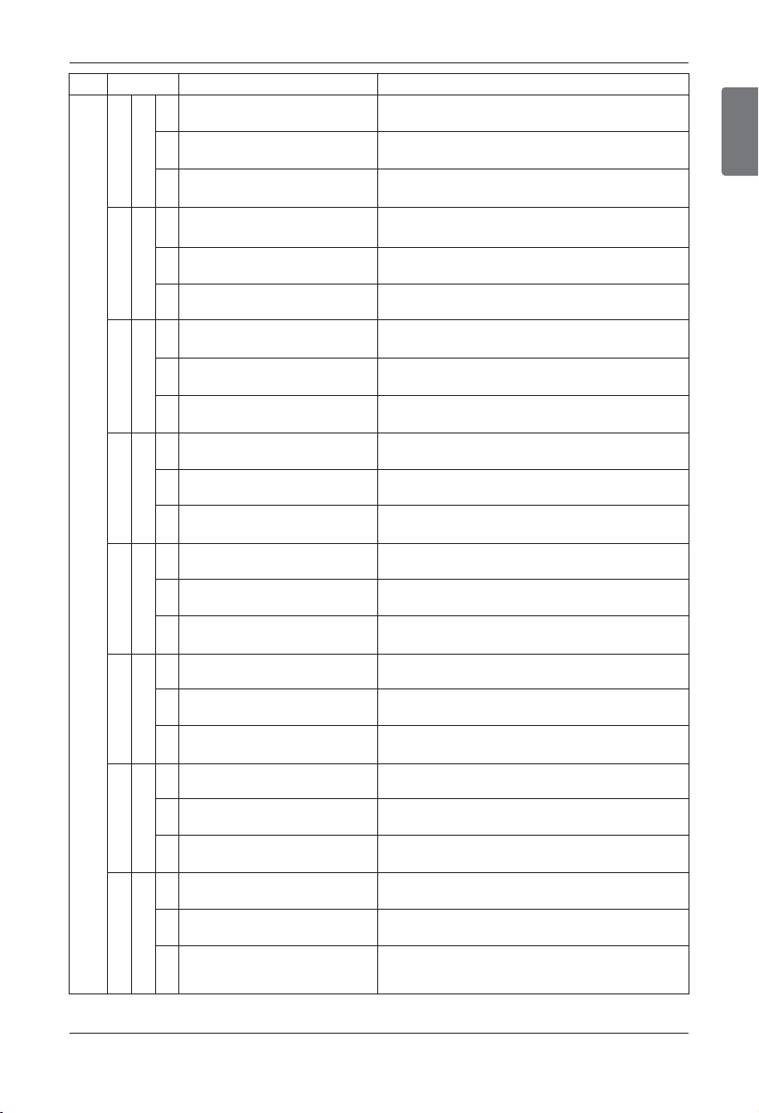
ENGLISH
Installation Manual 95
Test Run
System is turned off by excessive increase of high pressure of Mas-
ter Outdoor Unit
System is turned off by excessive increase of high pressure of
Slave1 Outdoor Unit
System is turned off by excessive increase of high pressure of
Slave2 Outdoor Unit
System is turned off by excessive decrease of low pressure of Mas-
ter Outdoor Unit
System is turned off by excessive decrease of low pressure of
Slave1 Outdoor Unit
System is turned off by excessive decrease of low pressure of
Slave2 Outdoor Unit
Master Outdoor Unit stayed under low condensing limit for 3 minutes
Slave1 Outdoor Unit stayed under low condensing limit for 3 minutes
Slave2 Outdoor Unit stayed under low condensing limit for 3 minutes
High Pressure of Master Outdoor Unit
High Pressure of Slave1 Outdoor Unit
High Pressure of Slave2 Outdoor Unit
Low Pressure of Master Outdoor Unit
Low Pressure of Slave1 Outdoor Unit
Low Pressure of Slave2 Outdoor Unit
Master Outdoor Unit Low Condensing
Ratio Limited
Slave1 Outdoor Unit Low Condensing
Ratio Limited
Slave2 Outdoor Unit Low Condensing
Ratio Limited
1
3 4 2
3
1
3 5 2
3
1
3 6 2
3
System is turned off by Master Outdoor Uunit Constant Speed Com-
pressor1 High Discharge Temperature
System is turned off by Slave1 Outdoor Unit Constant Speed Com-
pressor1 High Discharge Temperature
System is turned off by Slave2 Outdoor Unit Constant Speed Com-
pressor1 High Discharge Temperature
Master Outdoor Unit Constant Speed Com-
pressor1 High Discharge Temperature
Slave1 Outdoor Unit Constant Speed Com-
pressor1 High Discharge Temperature
Slave2 Outdoor Unit Constant Speed Com-
pressor1 High Discharge Temperature
Display Title Cause of Error
1
3 3 2
3
Outdoor unit related error
Master Outdoor Unit Inverter Compressor CT Sensor open or
short
Slave1 Outdoor Unit Inverter Compressor CT Sensor open or
short
Slave2 Outdoor Unit Inverter Compressor CT Sensor open or
short
Master Outdoor Unit Inverter Compressor
CT Sensor Fault
Slave1 Outdoor Unit Inverter Compressor
CT Sensor Fault
Slave2 Outdoor Unit Inverter Compressor
CT Sensor Fault
1
4 0 2
3
1
4 1 2
3
1
4 2 2
3
1
4 3 2
3
Master Outdoor Unit Inverter Compressor Discharge Tempera-
ture Sensor open or short
Slave1 Outdoor Unit Inverter Compressor Discharge Tempera-
ture Sensor open or short
Slave2 Outdoor Unit Inverter Compressor Discharge Tempera-
ture Sensor open or short
Master Outdoor Unit Low Pressure Sensor open or short
Slave1 Outdoor Unit Low Pressure Sensor open or short
Slave2 Outdoor Unit Low Pressure Sensor open or short
Master Outdoor Unit High Pressure Sensor open or short
Slave1 Outdoor Unit High Pressure Sensor open or short
Slave2 Outdoor Unit High Pressure Sensor open or short
Master Outdoor Unit Inverter Compressor
Discharge Temperature Sensor Fault
Slave1 Outdoor Unit Inverter Compressor
Discharge Temperature Sensor Fault
Slave2 Outdoor Unit Inverter Compressor
Discharge Temperature Sensor Fault
Master Outdoor Unit Low Pressure Sen-
sor Fault
Slave1 Outdoor Unit Low Pressure Sen-
sor Fault
Slave2 Outdoor Unit Low Pressure Sen-
sor Fault
Master Outdoor Unit High Pressure Sen-
sor Fault
Slave1 Outdoor Unit High Pressure Sen-
sor Fault
Slave2 Outdoor Unit High Pressure Sen-
sor Fault
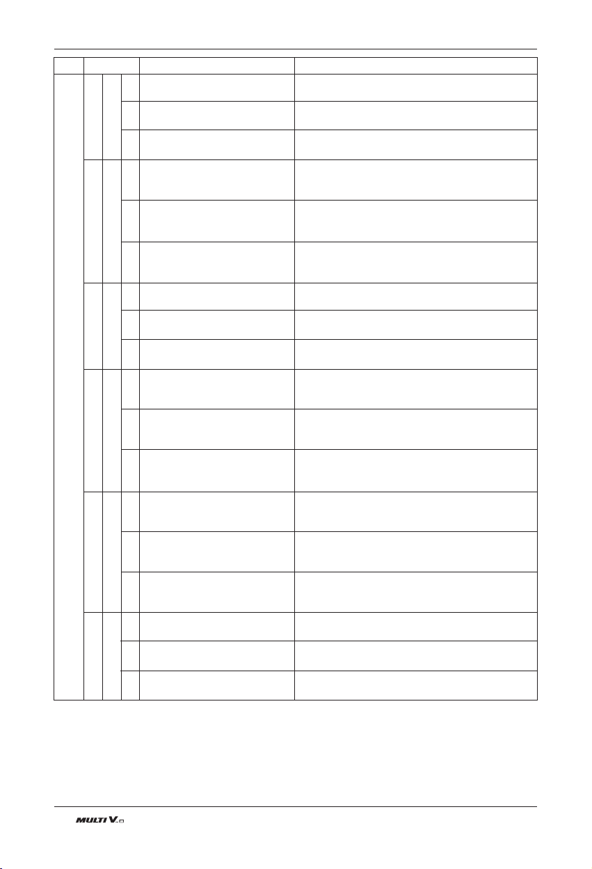
96 Outdoor Unit
Test Run
Display Title Cause of Error
Outdoor unit related error
Master Outdoor Unit Air Temperature Sensor open or
short
Slave1 Outdoor Unit Air Temperature Sensor open or
short
Slave2 Outdoor Unit Air Temperature Sensor open or
short
Master Outdoor Unit Heat Exchanger Temperature
Sensor(Front side) open or short
Slave1 Outdoor Unit Heat Exchanger Temperature
Sensor (Front side) open or short
Slave2 Outdoor Unit Heat Exchanger Temperature
Sensor(Front side) open or short
Master Outdoor Unit Suction Temperature Sensor open
or short
Slave1 Outdoor Unit Suction Temperature Sensor open
or short
Slave2 Outdoor Unit Suction Temperature Sensor open
or short
Master Outdoor Unit Constant Speed Compressor1
Discharge Temperature Sensor open or short
Slave1 Outdoor Unit Constant Speed Compressor1
Discharge Temperature Sensor open or short
Slave2 Outdoor Unit Constant Speed Compressor1
Discharge Temperature Sensor open or short
Master Outdoor Unit Constant Speed Compressor 2
Discharge Temperature Sensor open or short
Slave1 Outdoor Unit Constant Speed Compressor 2
Discharge Temperature Sensor open or short
Slave2 Outdoor Unit Constant Speed Compressor 2
Discharge Temperature Sensor open or short
Master Outdoor Unit IPM Temperature Sensor
short/open
Slave1 Outdoor Unit IPM Temperature Sensor
short/open
Slave2 Outdoor Unit IPM Temperature Sensor
short/open
Master Outdoor Unit Air Tempera-
ture Sensor Fault
Slave1 Outdoor Unit Air Tempera-
ture Sensor Fault
Slave2 Outdoor Unit Air Tempera-
ture Sensor Fault
Master Outdoor Unit Heat Ex-
changer Temperature Sensor
(Front side) Fault
Slave1 Outdoor Unit Heat Ex-
changer Temperature Sensor
(Front side) Fault
Slave2 Outdoor Unit Heat Ex-
changer Temperature Sensor
(Front side) Fault
Master Outdoor Unit Suction Tem-
perature Sensor Fault
Slave1 Outdoor Unit Suction Tem-
perature Sensor Fault
Slave2 Outdoor Unit Suction Tem-
perature Sensor Fault
Master Outdoor Unit Constant
Speed Compressor1 Discharge
Temperature Sensor Fault
Slave1 Outdoor Unit Constant
Speed Compressor1 Discharge
Temperature Sensor Fault
Slave2 Outdoor Unit Constant
Speed Compressor1 Discharge
Temperature Sensor Fault
Master Outdoor Unit Constant
Speed Compressor2 Discharge
Temperature Sensor Fault
Slave1 Outdoor Unit Constant
Speed Compressor2 Discharge
Temperature Sensor Fault
Slave2 Outdoor Unit Constant
Speed Compressor2 Discharge
Temperature Sensor Fault
Master Outdoor Unit Faulty IPM
Temperature Sensor
Slave1 Outdoor Unit Faulty IPM
Temperature Sensor
Slave2 Outdoor Unit Faulty IPM
Temperature Sensor
1
4 4 2
3
1
4 5 2
3
1
4 6 2
3
1
4 7 2
3
1
4 8 2
3
1
4 9 2
3
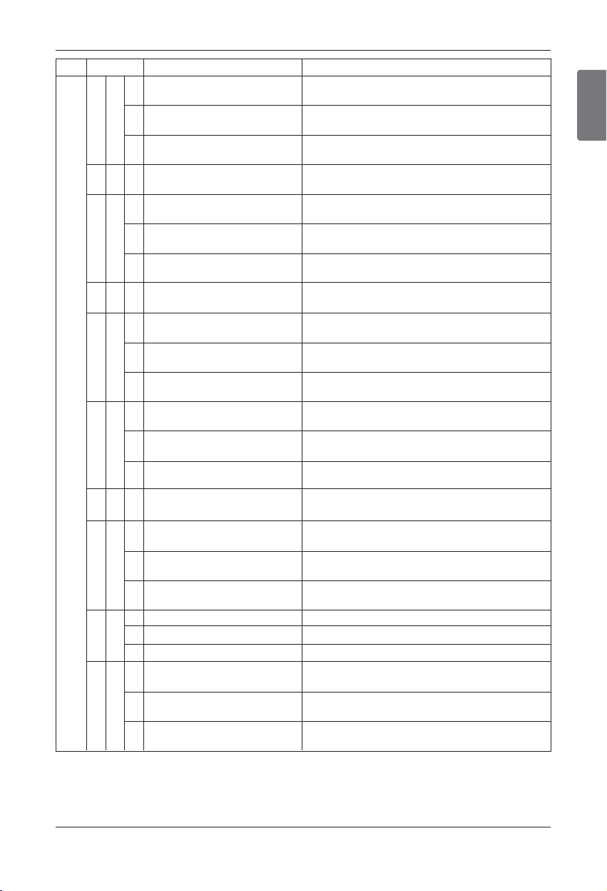
ENGLISH
Installation Manual 97
Omitting connection of Master outdoor unit
Omitting connection of Slave1 Outdoor Unit
Omitting connection of Slave2 Outdoor Unit
Excessive connection of indoor units compared to ca-
pacity of Outdoor Unit
Failing to receive inverter signal at main PCB of Master
Outdoor Unit
Failing to receive inverter signal at main PCB of Slave1
Outdoor Unit
Failing to receive inverter signal at main PCB of Slave2
Outdoor Unit
Failing to receive indoor unit signal at main PCB of
Outdoor Unit .
Reverse connection or omitting connection of R, S, T
power of Master Outdoor Unit
Reverse connection or omitting connection of R, S, T
power of Slave1 Outdoor Unit
Reverse connection or omitting connection of R, S, T
power of Slave2 Outdoor Unit
Master Outdoor Unit Controller part cannot receive inverter
control signals (usually happens after on-boarding)
Slave1 Outdoor Unit Controller part cannot receive inverter
control signals (usually happens after on-boarding)
Slave2 Outdoor Unit Controller part cannot receive inverter
control signals (usually happens after on-boarding)
In the case of installing smaller outdoor unit as master
unit
Access Error of Inverter PCB of Master Outdoor Unit
Access Error of Inverter PCB of Slave1 Outdoor Unit
Access Error of Inverter PCB of Slave2 Outdoor Unit
Restriction of Master Outdoor Unit
Restriction of Slave1 Outdoor Unit
Restriction of Slave2 Outdoor Unit
Constant1 CT Sensor open or short of Master Outdoor
Unit
Constant1 CT Sensor open or short of Slave1 Outdoor
Unit
Constant1 CT Sensor open or short of Slave2 Outdoor
Unit
Omitting connection of R, S, T
power of Master Outdoor Unit
Omitting connection of R, S, T
power of Slave1 Outdoor Unit
Omitting connection of R, S, T
power of Slave2 Outdoor Unit
Excessive capacity of indoor
units
Transmission error : inverter
PCB ’ Main PCB
Transmission error : inverter
PCB ’ Main PCB
Transmission error : inverter
PCB ’ Main PCB
Transmission error : indoor unit ’
main PCB of Outdoor Unit
Reverse connection of R, S, T
power of Master Outdoor Unit
Reverse connection of R, S, T
power of Slave1 Outdoor Unit
Reverse connection of R, S, T
power of Slave2 Outdoor Unit
Master Outdoor Unit Communication
Error with Inverter Controller
Slave1 Outdoor Unit Communication
Error with Inverter Controller
Slave2 Outdoor Unit Communication
Error with Inverter Controller
Error of series installation
Inverter PCB EEPROM Error of
Master Outdoor Unit
Inverter PCB EEPROM Error of
Slave1 Unit
Inverter PCB EEPROM Error of
Slave2 Unit
Master Outdoor Unit Fan Lock
Slave1 Outdoor Unit Fan Lock
Slave2 Outdoor Unit Fan Lock
Constant1 CT Sensor Error of
Master Outdoor Unit
Constant1 CT Sensor Error of
Slave1 Outdoor Unit
Constant1 CT Sensor Error of
Slave2 Outdoor Unit
Display Title Cause of Error
1
5 0 2
3
5 1 1
1
5 2 2
3
5 3 1
1
5 4 2
3
1
5 7 2
3
1
6 0 2
3
1
6 7 2
3
1
6 9 2
3
5 9 1
Outdoor unit related error
Test Run
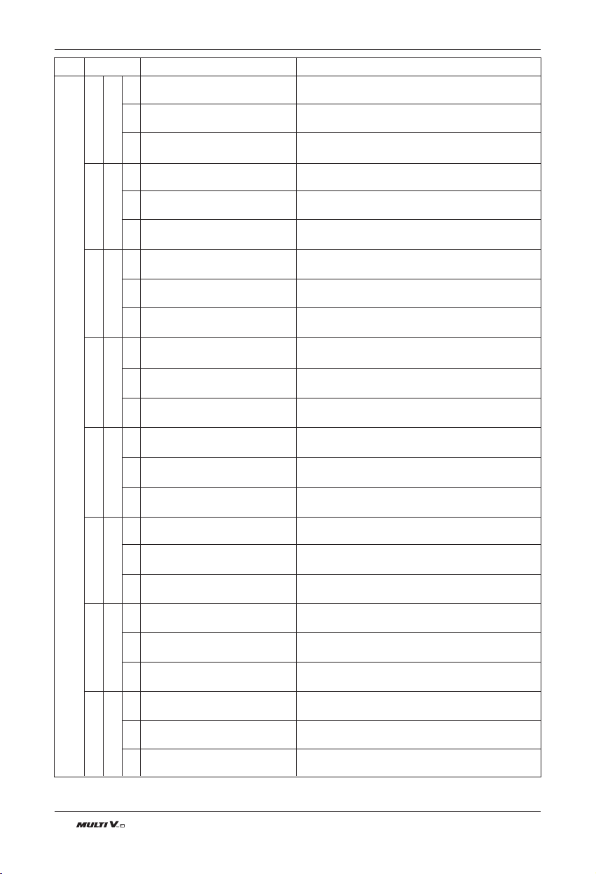
98 Outdoor Unit
Test Run
Constant2 CT Sensor open or short of Master Outdoor
Unit
Constant2 CT Sensor open or short of Slave1 Outdoor
Unit
Constant2 CT Sensor open or short of Slave2 Outdoor
Unit
Instant Over Current(Peak) of Master Outdoor Unit
PFC
Instant Over Current(Peak) of Slave1 Outdoor Unit
PFC
Instant Over Current(Peak) of Slave2 Outdoor Unit
PFC
Master Outdoor Unit Fan CT Sensor open or short
Slave1 Outdoor Unit Fan CT Sensor open or short
Slave2 Outdoor Unit Fan CT Sensor open or short
Constant2 CT Sensor Error of
Master Outdoor Unit
Constant2 CT Sensor Error of
Slave1 Outdoor Unit
Constant2 CT Sensor Error of
Slave2 Outdoor Unit
Instant Over Current(Peak) of
Master Outdoor Unit PFC
Instant Over Current(Peak) of
Slave1 Outdoor Unit PFC
Instant Over Current(Peak) of
Slave2 Outdoor Unit PFC
Master Outdoor Unit Fan CT Sen-
sor Error
Slave1 Outdoor Unit Fan CT Sen-
sor Error
Slave2 Outdoor Unit Fan CT Sen-
sor Error
Display Title Cause of Error
1
7 0 2
3
1
7 3 2
3
1
7 5 2
3
1
7 6 2
3
1
7 7 2
3
1
7 9 2
3
1
8 6 2
3
1
8 7 2
3
Outdoor unit related error
Master Outdoor Unit Fan DC Link High Voltage Error
Slave1 Outdoor Unit Fan DC Link High Voltage Error
Slave2 Outdoor Unit Fan DC Link High Voltage Error
Master Outdoor Unit Fan DC Link
High Voltage Error
Slave1 Outdoor Unit Fan DC Link
High Voltage Error
Slave2 Outdoor Unit Fan DC Link
High Voltage Error
Master Outdoor Unit Fan Current is over 10A
Slave1 Outdoor Unit Fan is over 10A
Slave2 Outdoor Unit Fan is over 10A
Master Outdoor Unit Fan Over
Current Error
Slave1 Outdoor Unit Fan Over
Current Error
Slave2 Outdoor Unit Fan Over
Current Error
Master Outdoor Unit Fan First Position Sensing Failure
Slave1 Outdoor Unit Fan First Position Sensing Failure
Slave2 Outdoor Unit Fan First Position Sensing Failure
Communication Fail Between Master Outdoor Unit
Main MICOM and EEPROM or omitting EEPROM
Communication Fail Between Slave1 Outdoor Unit
Main MICOM and EEPROM or omitting EEPROM
Communication Fail Between Slave2 Outdoor Unit
Main MICOM and EEPROM or omitting EEPROM
Communication Fail Between Master Outdoor Unit Fan
MICOM and EEPROM or omitting EEPROM
Communication Fail Between Slave1 Outdoor Unit Fan
MICOM and EEPROM or omitting EEPROM
Communication Fail Between Slave2 Outdoor Unit Fan
MICOM and EEPROM or omitting EEPROM
Master Outdoor Unit Fan Start
Failure Error
Slave1 Outdoor Unit Fan Start
Failure Error
Slave2 Outdoor Unit Fan Start
Failure Error
Master Outdoor Unit Main PCB
EEPROM Error
Slave1 Outdoor Unit Main PCB
EEPROM Error
Slave2 Outdoor Unit Main PCB
EEPROM Error
Master Outdoor Unit Fan PCB
EEPROM Error
Slave1 Outdoor Unit Fan PCB
EEPROM Error
Slave2 Outdoor Unit Fan PCB
EEPROM Error
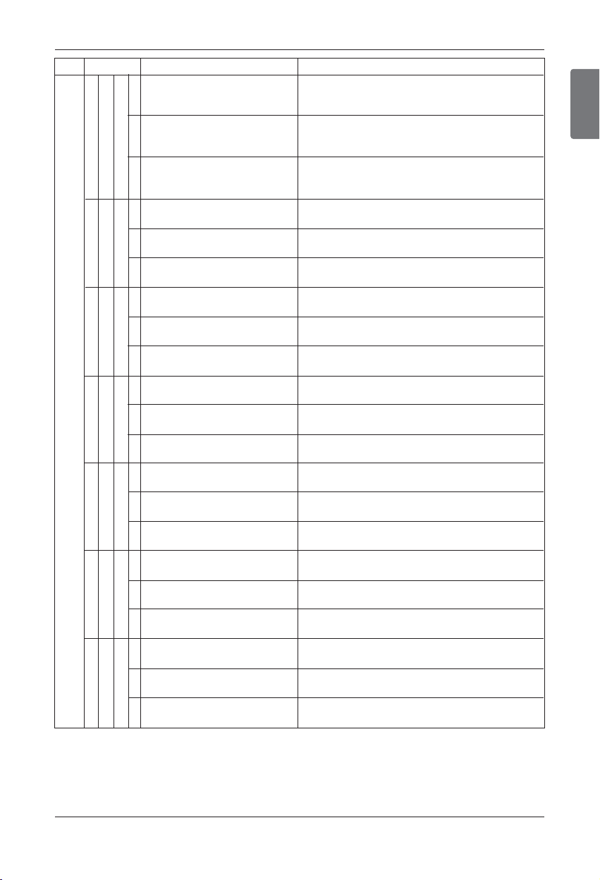
ENGLISH
Installation Manual 99
Test Run
Failing to receive Slave Unit signal at main PCB of
Master Outdoor Unit
Failing to receive master and other Slave Unit signal at
main PCB of Slave1 Outdoor Unit
Failing to receive master and other Slave Unit signal at
main PCB of Slave2 Outdoor Unit
Failing to receive fan signal at main PCB of master
unit.
Failing to receive fan signal at main PCB of Slave1
unit.
Failing to receive fan signal at main PCB of Slave2
unit.
Instant Over Current at Master Outdoor Unit Fan IPM
Instant Over Current at Slave1 Outdoor Unit Fan IPM
Instant Over Current at Slave2 Outdoor Unit Fan IPM
Master Outdoor Unit(208/230V) Fan DC Link Input Voltage is under 140V
Master Outdoor Unit(460V) Fan DC Link Input Voltage is under 380V
Slave1 Outdoor Unit(208/230V) Fan DC Link Input Voltage is under 140V
Slave1 Outdoor Unit(460V) Fan DC Link Input Voltage is under 380V
Slave2 Outdoor Unit(208/230V) Fan DC Link Input Voltage is under 140V
Slave2 Outdoor Unit(460V) Fan DC Link Input Voltage is under 380V
Liquid pipe temperature sensor of Master Outdoor
Unit is open or short
Liquid pipe temperature sensor of slave1 Outdoor Unit
is open or short
Liquid pipe temperature sensor of slave2 Outdoor Unit
is open or short
Master Outdoor Unit Subcooling Outlet Temperature
Sensor open or short
Slave1 Outdoor Unit Subcooling Outlet Temperature
Sensor open or short
Slave2 Outdoor Unit Subcooling Outlet Temperature
Sensor open or short
Pressure unbalance between Outdoor Units
Pressure unbalance between Outdoor Units
Pressure unbalance between Outdoor Units
Communication Error Between
Master Outdoor Unit and Other
Outdoor Unit
Communication Error Between
Slave1 Outdoor Unit and Other
Outdoor Unit
Communication Error Between
Slave2 Outdoor Unit and Other
Outdoor Unit
Master Outdoor Unit Fan PCB
Communication Error
Slave1 Outdoor Unit Fan PCB
Communication Error
Slave2 Outdoor Unit Fan PCB
Communication Error
Master Outdoor Unit FAN IPM
Fault Error
Slave1 Outdoor Unit FAN IPM
Fault Error
Slave2 Outdoor Unit FAN IPM
Fault Error
Master Outdoor Unit Fan DC Link
Low Voltage Error
Slave1 Outdoor Unit Fan DC Link
Low Voltage Error
Slave2 Outdoor Unit Fan DC Link
Low Voltage Error
Master Outdoor Unit Liquid pipe
Temperature Sensor Error
Slave1 Outdoor Unit Liquid pipe
Temperature Sensor Error
Slave2 Outdoor Unit Liquid pipe
Temperature Sensor Error
Master Outdoor Unit Subcooling
Outlet Temperature Sensor Error
Slave1 Outdoor Unit Subcooling
Outlet Temperature Sensor Error
Slave2 Outdoor Unit Subcooling
Outlet Temperature Sensor Error
Failure of operation mode conver-
sion at Master Outdoor Unit
Failure of operation mode conver-
sion at Slave1 Outdoor Unit
Failure of operation mode conver-
sion at Slave2 Outdoor Unit
Display Title Cause of Error
1
1 0 4 2
3
1
1 0 5 2
3
1
1 0 6 2
3
1
1 0 7 2
3
1
1 1 3 2
3
1
1 1 5 2
3
1
1 5 1 2
3
Outdoor unit related error
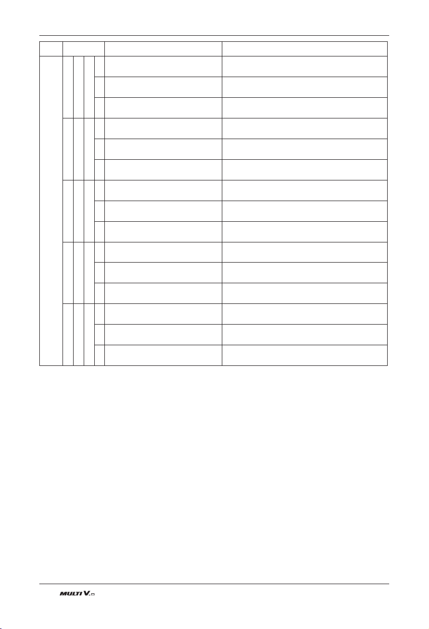
100 Outdoor Unit
Test Run
Display Title Cause of Error
1 7 3
1
Master Outdoor Unit Constant Speed
Compressor Fault
Comp locking, Check Valve leakage, comp dielectric break
down at Master Outdoor Unit
2
Slave1 Outdoor Unit Constant Speed
Compressor Fault
Comp locking, Check Valve leakage, comp dielectric at
Slave1 Outdoor Unit
3
Slave2 Outdoor Unit Constant Speed
Compressor Fault
Comp locking, Check Valve leakage, comp dielectric at
Slave2 Outdoor Unit
1 7 4
1
Master outdoor unit rated speed 2 con-
denser over-current
Master Outdoor Unit rated speed 2 condenser burned /
locked or fault by over-current
2
Slave1 outdoor unit rated speed 2 con-
denser over-current
Slave1 Outdoor Unit rated speed 2 condenser burned /
locked or fault by over-current
3
Slave2 outdoor unit rated speed 2 con-
denser over-current
Slave2 Outdoor Unit rated speed 2 condenser burned /
locked or fault by over-current
1 8 2
1
Master outdoor unit Main Board Main-
Sub Micom communication error
Master Outdoor Unit Main Board Main-Sub Micom commu-
nication failed
2
Slave1 outdoor unit Main Board Main-
Sub Micom communication error
Slave1 Outdoor Unit Main Board Main-Sub Micom commu-
nication failed
3
Slave2 outdoor unit Main Board Main-
Sub Micom communication error
Slave2 Outdoor Unit Main Board Main-Sub Micom commu-
nication failed
1 9 3
1
Excessive increase of Master Outdoor
Unit Fan PCB Heat Sink Temperature
Master Outdoor Unit Fan Inverter PCB Temperature is
Over 95°C
2
Excessive increase of Slave1 Outdoor
Unit Fan PCB Heat Sink Temperature
Slave1 Outdoor Unit Fan Inverter PCB Temperature is
Over 95°C
3
Excessive increase of Slave2 Outdoor
Unit Fan PCB Heat Sink Temperature
Slave2 Outdoor Unit Fan Inverter PCB Temperature is
Over 95°C
1 9 4
1
Master Outdoor Unit Fan PCB Heat Sink
Temperature Sensor Error
Master Outdoor Unit Fan PCB Heat Sink Temperature
Sensor open or short
2
Slave1 Outdoor Unit Fan PCB Heat Sink
Temperature Sensor Error
Slave1 Outdoor Unit Fan PCB Heat Sink Temperature
Sensor open or short
3
Slave2 Outdoor Unit Fan PCB Heat Sink
Temperature Sensor Error
Slave2 Outdoor Unit Fan PCB Heat Sink Temperature
Sensor open or short
Outdoor unit related error
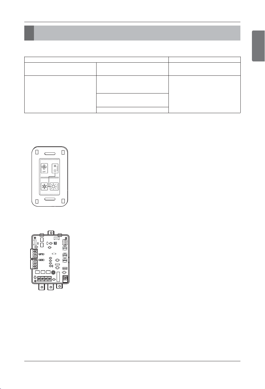
ENGLISH
Installation Manual 101
New Function
New Function
n Multi V III provides as following new functions.
h If you want to get more details, refer to each installation Manuals.
n Out Feature
• Cool/ Heat Selector
• ODU Dry contact
New Function Applied item
Cool/Heat selector (PRDSBM)
Cooling/ Heating/ Fan
Cooling/ Heating/ All OFF
ODU
Solution Accessory
ODU Dry contact (PQDSBDCVM0)
Demand control
-. Low load operation
-. DDC control (DC0~10V Input)
ODU
Solution Accessory
ODU Fan Low speed control
(Night low noise operation)
Error alarm
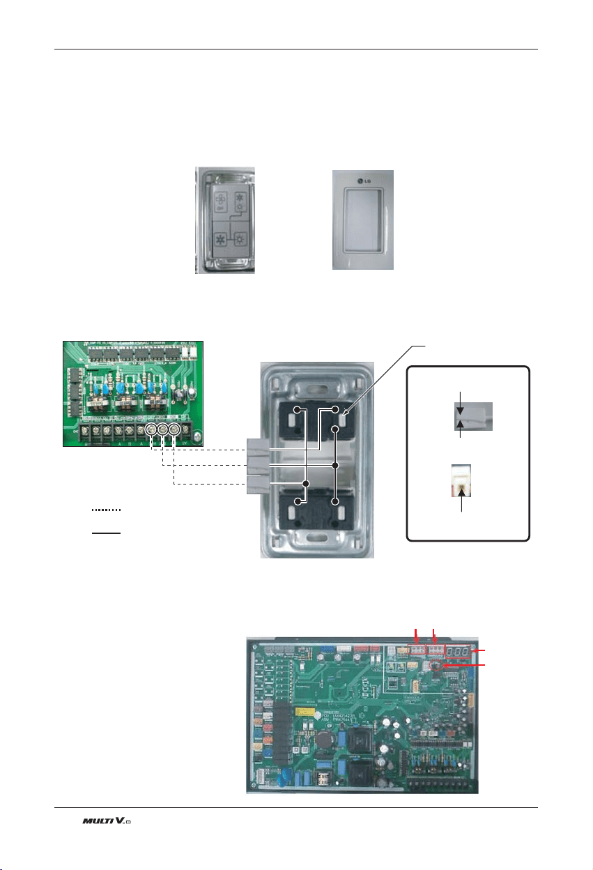
102 Outdoor Unit
New Function
1. Cool/ Heat selector
Cool/ Heat Selector has provided two different functions.
- Cooling/ heating/ Fan lock mode
- Cooling/ heating/ All OFF mode
[Installation]
1. Check the contents of Cool/ Heat Selector
2. Connect Outdoor Main PCB and Cool/ Heat Selector.
-. Connect terminals on the back side of Cool/Heat Selector to terminal of Outdoor as show
¨≠
GNDGND
¨≠
GND
< Outdoor Main PCB >
- Insert wire method -
shows field wiring
connected wiring
Push arrow direction.
Insert wire to connector.
Push Button
<Outdoor Dry Contact Back Side >
¨
≠
¨
≠
GNDGNDGND
1
2
3
4
1
2
3
4
❈ Communication line length can be maximum 300m, use communication line as thick as 1.25mm
2
.
<Front Case><Outdoor Dry Contact Main Body>
[setting]
1. Set DIP S/W according to DIP S/W
setting table.(5,6,11,12)
2. Push Black button on SVC PCB
3. Select number as below at 7-segment
“0” : Cooling/ Heating / Fan lock mode
“1” : Cooling/ Heating/ All OFF Mode
4. After Selecting, DIP S/W OFF(11,12 )
SW01B
SW02B
Setting Button
7-Segment
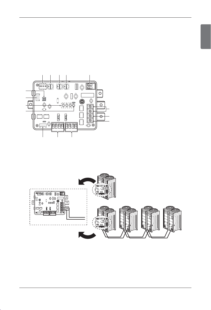
ENGLISH
Installation Manual 103
New Function
2. ODU Dry contact
ODU Dry contact has provided Three different functions.
- Demand control
- Night Low Noise control
- Error Alarm Monitoring function
[ODU Dry contact]
- Feature and Parts Naming
- Installation
1. ODU Dry contact single installation : Connect with ODU both single Unit and Series.
1. SWDIP : Switch to select main function
2. SW_Address2 : Switch to set a upper
address of the outdoor unit
3. SW_Address1 : Switch to set a lower
address of the outdoor unit
4. SW_STEP : Switch to select a control mode.
5. CN_PWR : DC Input terminal
6. ERROR : Error display with relay contact
7. BUS-A : RS-485 (+) Terminal
8. BUS-B : RS-485 (-) Terminal
9. CN_CAPACITY : Signal input terminal to
control a capacity of outdoor unit
10. CN_SPEED/CAP : Signal input terminal for
Analog Input/Low noise operation
11. CN_OUT : Outdoor unit connector
12. LED1 : Display LED for RS-485 status
13. LED01G,02G,03G : Display LED for
communication status
14. CN_JIG : Connector for writing program
15. SW1 : Reset switch
12 34 5
6
7
8
91011
12
13
14
15
RS-485
BUS_B
BUS_A
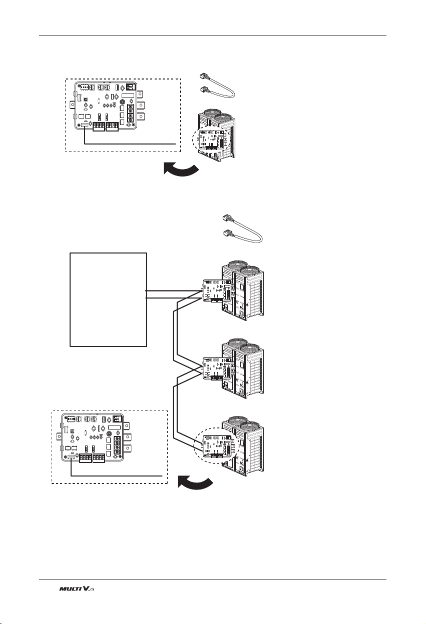
104 Outdoor Unit
New Function
2. ODU Dry contact with Central controller
: With Single Outdoor unit
: With Series Outdoor units
CN_OUT
TTL
Multi-V
WIRE ASSY 1(1EA)
BUS_B
BUS_A
Central
Control
Devices
Multi-V
WIRE ASSY 1(1EA)
CN_OUT
TTL
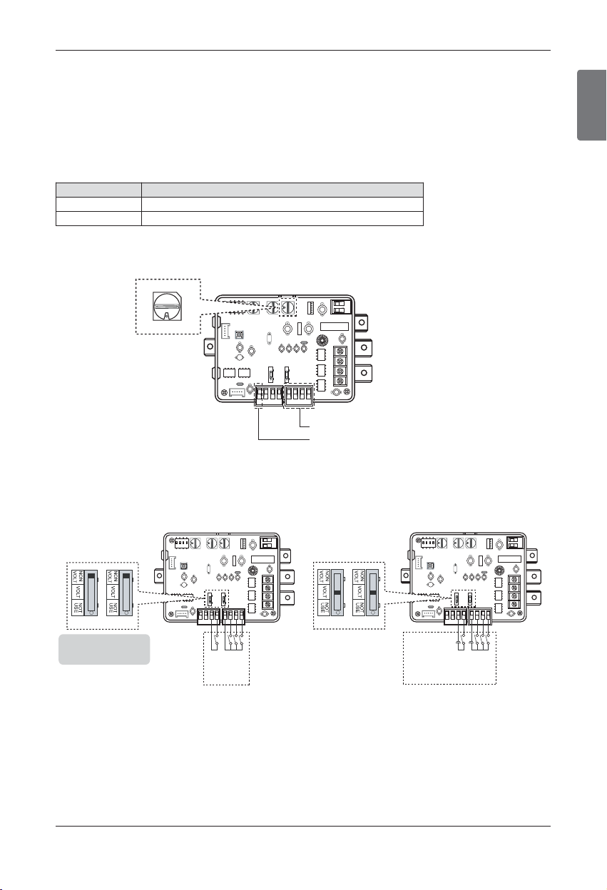
ENGLISH
Installation Manual 105
New Function
2.1 Demand Control
ODU Dry contact has provided Two different methods for Demand control
- Using Contact signal
: High/ Low pressure value s are changed by setting value of Rotary S/W
- Using Analog signal with DDC Module
: High/ Low pressure value s are changed by setting value of DDC Module.(DC 0~10V)
[Rotary S/W setting ]
- Each connecting methods
1. Using Contact signal
<Without External power source> <With External power source>
[Setting ]
SW_STEP Input Signal
0, 1, 2, 3, 4, 5, 6 Contact signal
D, E Analog signal
SW_STEP
Using Contact signal
Using Analog signal with DDC Module
LG does not
supply this section
(Field supply)
Notes
Do not input the voltage signal in
"NON VOLT" setting mode otherwise
it will cause serious damage
SW_VOLT2 SW_VOLT1
Input_3
Input_2
Input_1
comm
Input_LNO
comm
LG does not
supply this section
(Field supply)
SW_VOLT2 SW_VOLT1
Input_3
Input_2
Input_1
comm
Input_LNO
comm
Connect separate
External voltage of
DC12V
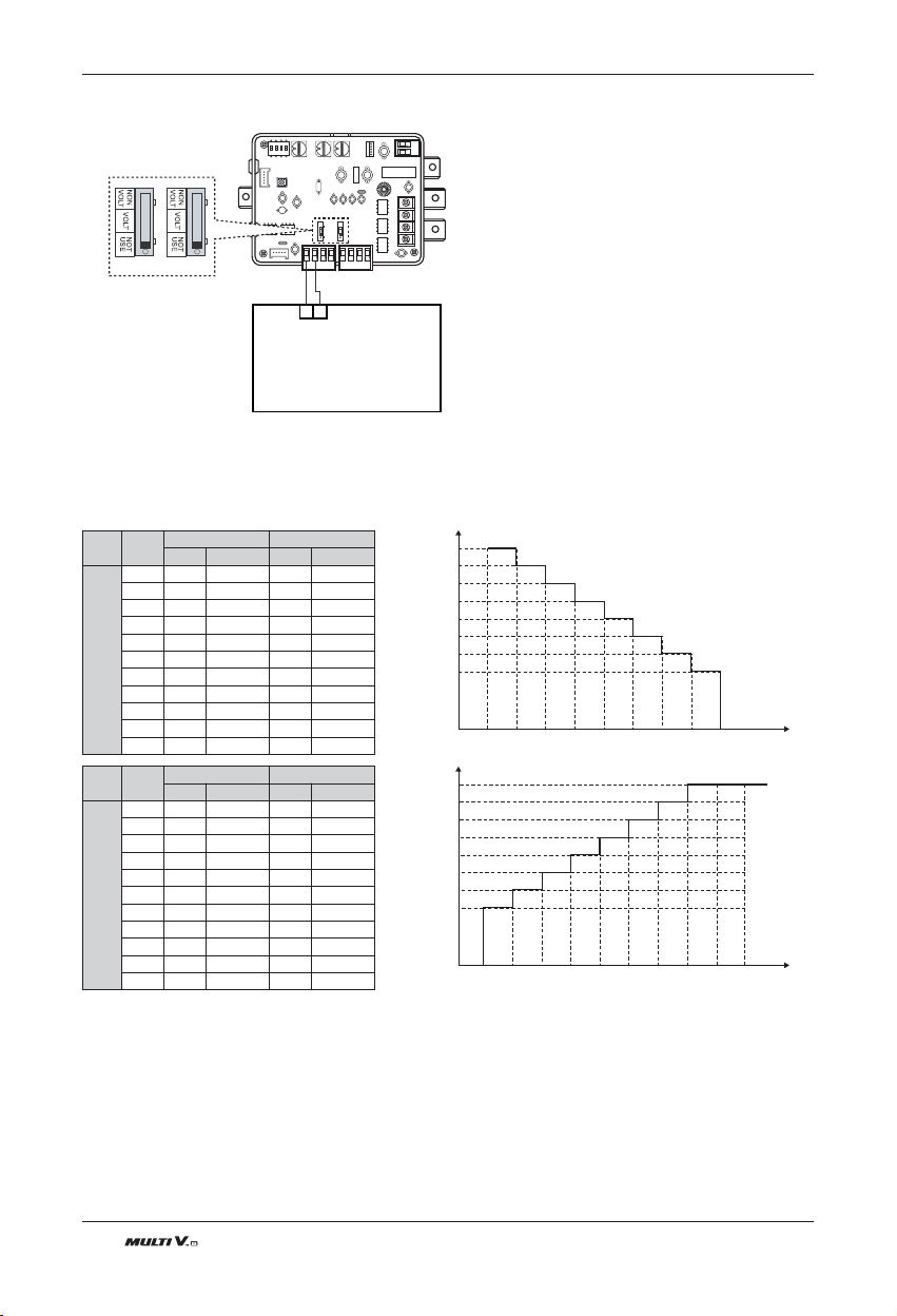
106 Outdoor Unit
New Function
2. Using Analog signal with DDC Module
SW_VOLT2 SW_VOLT1
Direct Digital Controller
GND
DC 0~10V
input
100%
90%
80%
70%
60%
50%
45%
40%
0V 1V 2V 3V 4V 5V 6V 7V 8V 9V 10V
0 1 23 45 67 8 910
Comp.
OFF
Non
Control
Comp.
OFF
System
OFF
Signal
Input
Step
Performance output of the ODU
100%
90%
80%
70%
60%
50%
45%
40%
0V 1V 2V 3V 4V 5V 6V 7V 8V 9V 10V
9 8 76 54 32 1 1 1
Signal
Input
Step
Performance output of the ODU
[Control Value]
- Using Contact signal
Rotary
S/W
Volt
Cooling Heating
Step Control Step Control
D
0 0 Not-Control 0
Not-Control
1 1 100% 0 100%
2 2 90% 0 90%
3 3 80% 0 80%
4 4 70% 0 0 70%
5 5 60% 0 60%
6 6 50% 0 50%
7 7 45% 0 45%
8 8 40% 0 40%
9 9 Comp OFF 0 Comp OFF
10 10 All OFF 0 All OFF
Rotary
S/W
Volt
Cooling Heating
Step Control Step Control
E
0 9 Comp OFF 0
Comp OFF
1 8 40% 0 40%
2 7 45% 0 45%
3 6 52% 0 50%
4 5 60% 0 0 60%
5 4 70% 0 70%
6 3 80% 0 80%
7 2 90% 0 90%
8 1 100% 0 100%
9 1 100% 0 100%
10 1 100% 0 100%

ENGLISH
Installation Manual 107
SW_
STEP
Input_1 Input_2 Input_3
Comp capacity
Of outdoor unit(%)
0
0 0 0 No control
1 0 0 70
0 1 0 40
0 0 1 COMP OFF
1
0 0 0 No control
1 0 0 70
0 1 0 50
0 0 1 COMP OFF
2
0 0 0 No control
1 0 0 80
0 1 0 50
0 0 1 COMP OFF
3
0 0 0 No control
100 70
0
10 40
00
1 ALL OFF
4
0 0 0 No control
100 70
0
10 50
00
1 ALL OFF
5
0 0 0 No control
100 80
0
10 50
00
1 ALL OFF
6
0 0 0 No control
100 50
0
1 0 COMP OFF
00
1 ALL OFF
- Using Analog signal with DDC Module
Non
Control
100%
90%
80%
70%
60%
50%
45%
40%
0V 1V 2V 3V 4V 5V 6V 7V 8V 9V 10V
0 1 23 45 67 8 910
Comp.
OFF
System
OFF
Signal
Input
Step
Performance output of the ODU
New Function
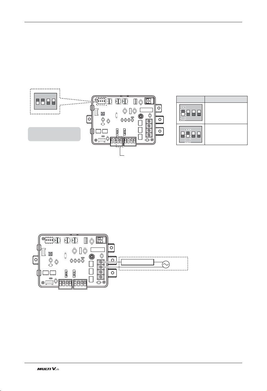
108 Outdoor Unit
2.2 Night Low Noise control
ODU Dry contact has provided Two methods for Night Low Noise Control
- Automatically operating
: Using previous method
- Manual operating
: Using simple switch and timer
[Setting]
- For ODU Dry contact
- For Outdoor unit
Refer to DIP S/W setting table
2.3 Error Alarm monitoring
ODU Dry contact has provided Error Alarm monitoring function
Notice for system fault information by buzzer or warning lamp.
Occurring fault is not only ODUs but also IDUs.
[Setting]
- Note
AC Power : 3A @250V
DC Power : 3A @30V
ON
L1 2 3 4
Connect with S/W or Timer for
Night Low Noise Control
Notes
Default State is L1: ON, L2: ON
Position Function
ON
L1 2 3 4
ON : Master Mode
OFF : Slave Mode
ON
L1 2 3 4
ON : Enable Low Noise
Operation
OFF : Disable Low Noise
Operation
Error Display
Field Supply
(Depends on Operation
display power type)
Power
AC or DC
New Function
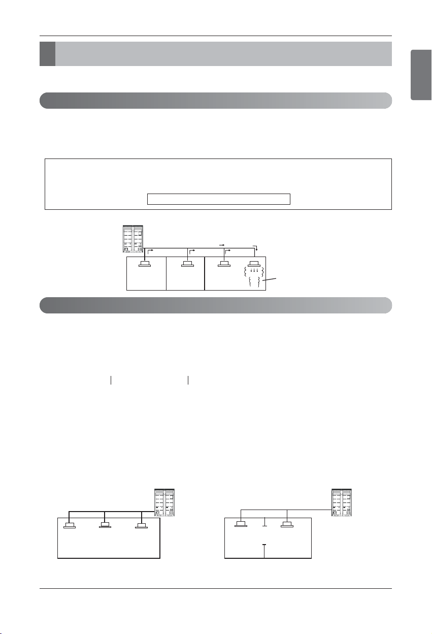
ENGLISH
Installation Manual 109
Caution For Refrigerant Leak
The installer and system specialist shall secure safety against leakage according to local regulations or standards.
The following standards may be applicable if local regulations are not available.
Though the R410A refrigerant is harmless and incombustible itself , the room to equip the air conditioner should be large to
such an extent that the refrigerant gas will not exceed the limiting concentration even if the refrigerant gas leaks in the room.
n Limiting concentration
Check limiting concentration along following steps and take appropriate measure depending on the situation.
n Calculate amount of all the replenished refrigerant (kg) per each refrigerant
system.
n Calculate minimum room capacity
Calculate room capacity by regarding a portion as one room or the smaller room.
(1) Without partition
(2) With partition and with opening which serve as
passage of air to adjoining room
Caution For Refrigerant Leak
Introduction
Checking procedure of limiting concentration
Limiting concentration is the limit of Freon gas concentration where immediate measures can be taken with-
out hurting human body when refrigerant leaks in the air. The limiting concentration shall be described in the
unit of kg/m
3
(Freon gas weight per unit air volume) for facilitating calculation.
Limiting concentration: 0.44kg/m
3
(R410A)
Outdoor unit
(No.1 system)
Flow of
refrigerant
Indoor unit
Room where refrigerant leaks
(Refrigerant of the whole No.1
system flows out.)
Amount of additional
replenished refrigerant
Total amount of replenished
refrigerant in refrigerant
facility (kg)
+
=
Note : In case one refrigerant facility is
divided into 2 or more refrigerant
systems and each system is
independent, amount of replenished
refrigerant of each system shall be
adopted.
Outdoor unit
Indoor unit
Outdoor unit
Indoor unit
Opening
Partition
In the case of opening
without door , or 0.15
% or more openings
(to floor space) both
above and below door)
Amount of replenished
refrigerant per one outdoor
unit system
Amount of replenished
refrigerant at factory shipment
Amount of additionally
replenished refrigerant
depending on piping
length or piping
diameter at customer
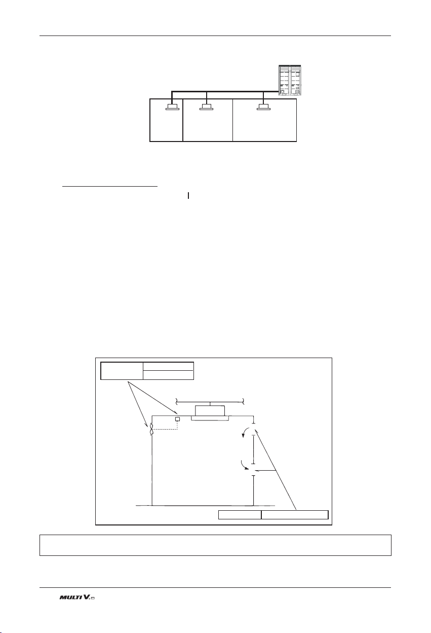
110 Outdoor Unit
Caution For Refrigerant Leak
(3) With partition and without opening which serve as passage of air to adjoining room
n Calculate refrigerant concentration
n In case the concentration exceeds the limit
When the concentration exceeds the limit, change original plan or take one of the countermeasures
shown below:
• Countermeasure 1
Provide opening for ventilation.
Provide 0.15% or more opening to floor space both above and below door, or provide opening without
door.
• Countermeasure 2
Provide gas leak alarm linked with mechanical ventilator.
Reducing the outdoor refrigerant qty.
Pay a special attention to the place, such as a basement, etc. where refrigerant can stay, since refrigerant is
heavier than air.
Outdoor unit
Indoor unit
Smallest
room
(R410A)
≤
Refrigerant concentration
(kg/m
3
)
Total amount of replenished
refrigerant in refrigerant facility (kg)
Capacity of smallest room where
indoor unit is installed (m
3
)
In case the result of calculation exceeds
the limiting concentration, perform the
same calculations by shifting to the
second smallest, and the third smallest
rooms until at last the result is below the
limiting concentration.
Countermeasure 2
Gas leak alarm
Mechanical ventilator
Countermeasure 1
Opening effective to ventilation
Indoor unit
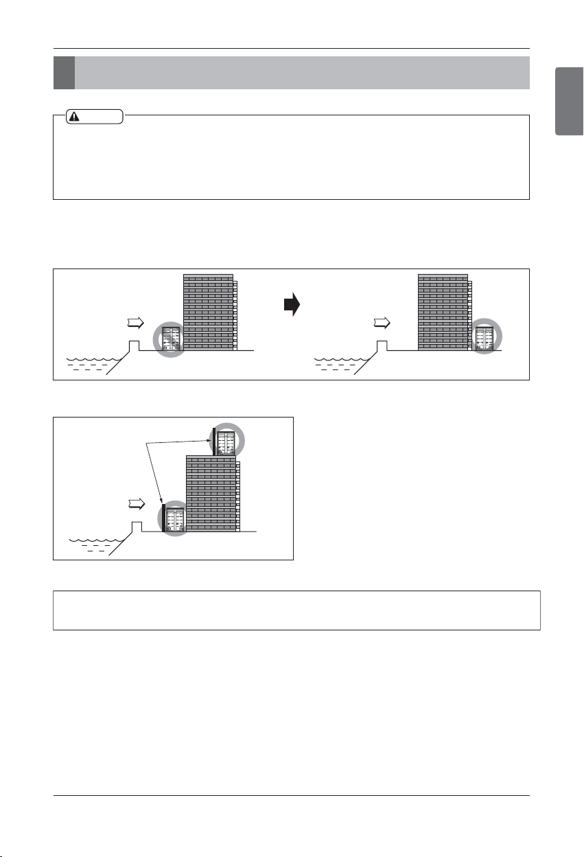
ENGLISH
Installation Manual 111
Installation guide at the seaside
Installation guide at the seaside
1.
Air conditioners should not be installed in areas where corrosive gases, such as acid or alkaline gas, are produced.
2. Do not install the product where it could be exposed to sea wind (salty wind) directly. It can result corrosion
on the product. Corrosion, particularly on the condenser and evaporator fins, could cause product malfunc-
tion or inefficient performance.
3. If outdoor unit is installed close to the seaside, it should avoid direct exposure to the sea wind. Otherwise it
needs additional anticorrosion treatment on the heat exchanger.
Selecting the location(Outdoor Unit)
1) If the outdoor unit is to be installed close to the seaside, direct exposure to the sea wind should be avoided.
Install the outdoor unit on the opposite side of the sea wind direction.
2) In case, to install the outdoor unit on the seaside, set up a windbreak not to be exposed to the sea wind.
3) Select a well-drained place.
• It should be strong enough like concrete to prevent
the sea wind from the sea.
• The height and width should be more than 150% of
the outdoor unit.
• It should be kept more than 70 cm of space
between outdoor unit and the windbreak for easy
air flow.
Sea wind Sea wind
Sea wind
Windbreak
CAUTION
1. Periodic ( more than once/year ) cleaning of the dust or salt particles stuck on the heat exchanger by using
water.
112 Outdoor Unit

USA, press #2 for PTAC, TTW
USA, press #3 for DFS, Multi V
CANADA
888-865-3026
888-865-3026
1-888-LG-Canada
www.lge.com
LG Customer Information Center
Register your product Online!
LGEUS
LG Electronics, Air conditioning Division
1000 Sylvan Ave., Englewood Cliffs, NJ 07632
LGECI
LG ELECTRONICS CANADA INC.
20 NORELCO DRIVE.
NORTH YORK, ONTARIO M9L 2X6.