Issue 10/2020 Art. No. 7001-0359
Operating Manual
BD
-S / BD-S-UL (E1)
Incubators with natural convection
ED
-S / ED-S-UL (E1)
Drying and heating ovens with natural
convection
FD
-S / FD-S-UL (E1)
Drying and heating ovens with forced
convection
with R-S microprocessor temperature controller
Model
Model version
Art. No.
BD-S 56 BDS056-230V 9090-0016, 9190-0016
BD-S-UL 56 BDS056UL-120V 9090-0017, 9190-0017
BD-S 115 BDS115-230V 9090-0022, 9190-0022
BD-S-UL 115 BDS115UL-120V 9090-0023, 9190-0023
ED-S 56 EDS056-230V 9090-0014, 9190-0014
ED-S-UL 56 EDS056UL-120V 9090-0015, 9190-0015
ED-S 115 EDS115-230V 9090-0020, 9190-0020
ED-S-UL 115 EDS115UL-120V 9090-0021, 9190-0021
FD-S 56 FDS056-230V 9090-0018, 9190-0018
FD-S-UL 56 FDS056UL-120V 9090-0019, 9190-0019
FD-S 115 FDS115-230V 9090-0024, 9190-0024
FD-S-UL 115 FDS115UL-120V 9090-0025, 9190-0025
BINDER GmbH
Address: Post office box 102, 78502 Tuttlingen, Germany Phone: +49 7462 2005 0
Fax: +49 7462 2005 100 Internet: http://www.binder-world.com
E-mail: info@binder-world.com Service Hotline: +49 7462 2005 555
Service Fax: +49 7462 2005 93 555 Service E-Mail: customerservice@binder-world.com
Service Hotline USA: +1 866 885 9794 or +1 631 224 4340 x3
Service Hotline Asia Pacific: +852 390 705 04 or +852 390 705 03
Service Hotline Russia and CIS: +7 495 988 15 16

BD-S / BD-S-UL, ED-S / ED-S-UL, FD-S / FD-S-UL (E1) 10/2020 page 2/59
Content
1. SAFETY .................................................................................................................. 4
1.1 Legal considerations ........................................................................................................................... 4
1.2 Structure of the safety instructions ...................................................................................................... 4
1.2.1 Signal word panel ...................................................................................................................... 4
1.2.2 Safety alert symbol .................................................................................................................... 5
1.2.3 Pictograms ................................................................................................................................. 5
1.2.4 Word message panel structure ................................................................................................. 6
1.3 Localization / position of safety labels on the chamber ...................................................................... 6
1.4 Type plate............................................................................................................................................ 7
1.5 General safety instructions on installing and operating the chambers ............................................... 8
1.6 Intended use ....................................................................................................................................... 9
2. CHAMBER DESCRIPTION .................................................................................. 10
2.1 Chamber overview ............................................................................................................................ 11
2.2 Triangular instrument panel .............................................................................................................. 12
3. COMPLETENESS OF DELIVERY, TRANSPORTATION, STORAGE, AND
INSTALLATION .................................................................................................... 12
3.1 Unpacking, and checking equipment and completeness of delivery ................................................ 12
3.2 Guidelines for safe lifting and transportation ..................................................................................... 13
3.3 Storage .............................................................................................................................................. 13
3.4 Location of installation and ambient conditions ................................................................................ 13
4. INSTALLATION .................................................................................................... 14
4.1 Installing the racks ............................................................................................................................ 14
4.2 Connection to an exhaust/ventilation system (optional) ................................................................... 15
4.3 Electrical connection ......................................................................................................................... 15
5. R-S CONTROLLER OVERVIEW .......................................................................... 16
5.1 Menu structure overview ................................................................................................................... 17
6. START UP ............................................................................................................ 18
6.1 Adjusting air change .......................................................................................................................... 18
7. TEMPERATURE SET -POINT ENTRY ................................................................ 18
8. SELECTING THE TEMPERATURE UNIT ............................................................ 19
8.1 Setting the temperature unit .............................................................................................................. 19
9. OVERTEMPERATURE PROTECTION ................................................................ 19
9.1 Overtemperature protective device (class 1) .................................................................................... 19
9.2 Safety controller ................................................................................................................................ 20
9.2.1 Setting the safety controller ..................................................................................................... 20
9.2.2 Alarm message and proceeding in case of an alarm .............................................................. 21
10. TIMER FUNCTION “DELAYED OFF” ................................................................. 21
10.1 Setting the timer run-time .................................................................................................................. 21
11. RAMP FUNCTION ................................................................................................ 22
11.1 Setting the ramp ................................................................................................................................ 22
11.2 Setting the gradient ........................................................................................................................... 23
11.3 Display of the ramp course ............................................................................................................... 23
11.4 Turning off the ramp function ............................................................................................................ 23

BD-S / BD-S-UL, ED-S / ED-S-UL, FD-S / FD-S-UL (E1) 10/2020 page 3/59
12. OPTIONS .............................................................................................................. 24
12.1 Data logger kits (option) .................................................................................................................... 24
13. MAINTENANCE, CLEANING, AND SERVICE .................................................... 24
13.1 Maintenance intervals, service .......................................................................................................... 24
13.2 Cleaning and decontamination ......................................................................................................... 25
13.2.1 Cleaning .................................................................................................................................. 25
13.2.2 Decontamination ...................................................................................................................... 26
13.3 Sending the chamber back to BINDER GmbH ................................................................................. 27
14. DISPOSAL............................................................................................................ 28
14.1 Disposal of the transport packing ...................................................................................................... 28
14.2 Decommissioning .............................................................................................................................. 28
14.3 Disposal of the chamber in the Federal Republic of Germany ......................................................... 28
14.4 Disposal of the chamber in the member states of the EU except for the Federal Republic of
Germany............................................................................................................................................ 29
14.5 Disposal of the chamber in non-member states of the EU ............................................................... 30
15. TROUBLESHOOTING ......................................................................................... 31
16. TECHNICAL DESCRIPTION ................................................................................ 32
16.1 Factory calibration and adjustment ................................................................................................... 32
16.2 Definition of usable volume ............................................................................................................... 32
16.3 Over current protection ..................................................................................................................... 32
16.4 Technical data ................................................................................................................................... 33
16.5 Equipment and options (extract) ....................................................................................................... 35
16.6 Accessories and spare parts (extract) .............................................................................................. 35
16.7 Dimensioned drawings ...................................................................................................................... 36
16.7.1 BD-S / BD-S-UL 56 .................................................................................................................. 36
16.7.2 BD-S / BD-S-UL 115 ................................................................................................................ 37
16.7.3 ED-S / ED-S-UL 56 .................................................................................................................. 38
16.7.4 ED-S / ED-S-UL 115 ................................................................................................................ 39
16.7.5 FD-S / FD-S-UL 56 .................................................................................................................. 40
16.7.6 FD-S / FD-S-UL 115 ................................................................................................................ 41
17. CERTIFICATES AND DECLARATIONS OF CONFORMITY ............................... 42
17.1 EU Declaration of Conformity for BD-S ............................................................................................. 42
17.2 EU Declaration of Conformity for ED-S ............................................................................................. 44
17.3 EU Declaration of Conformity for FD-S ............................................................................................. 46
17.4 Certificate for the GS mark of conformity of the “VDE Prüf- und Zertifizierungsinstitut” (Testing and
Certification Institute of the Association for Electrical, Electronic and Information Technologies) ... 48
17.5 Certificate of UL Compliance from Underwriters Laboratories Inc.
®
................................................. 52
18. PRODUCT REGISTRATION ................................................................................ 53
19. CONTAMINATION CLEARANCE CERTIFICATE ............................................... 54
19.1 For chambers located outside the USA and Canada ....................................................................... 54
19.2 For chambers located in the USA and Canada ................................................................................ 57
BD-S / BD-S-UL, ED-S / ED-S-UL, FD-S / FD-S-UL (E1) 10/2020 page 4/59
Dear customer,
For the correct operation of the chambers, it is important that you read this operating manual completely
and carefully and observe all instructions as indicated. Failure to read, understand and follow the instruc-
tions may result in personal injury. It can also lead to damage to the chamber and/or poor equipment
performance
1. Safety
This operating manual is part of the components of delivery. Always keep it handy for reference. The
device should only be operated by laboratory personnel especially trained for this purpose and familiar
with all precautionary measures required for working in a laboratory. Observe the national regulations on
minimum age of laboratory personnel To avoid injuries and damage observe the safety instructions of the
operating manual.
WARNING
Failure to observe the safety instructions.
Serious injuries and chamber damage.
Observe the safety instructions in this operating manual
Carefully read the complete operating instructions of the chambers.
1.1 Legal considerations
This operating manual is for informational purposes only. It contains information for installing, start-up,
operation and maintenance of the product. Note: the contents and the product described are subject to
change without notice.
Understanding and observing the instructions in this operating manual are prerequisites for hazard-free
use and safety during operation and maintenance. In no event shall BINDER be held liable for any dam-
ages, direct or incidental arising out of or related to the use of this manual.
This operating manual cannot cover all conceivable applications. If you would like additional information,
or if special problems arise that are not sufficiently addressed in this manual, please ask your dealer or
contact us directly by phone at the number located on page one of this manual
Furthermore, we emphasize that the contents of this operating manual are not part of an earlier or exist-
ing agreement, description, or legal relationship, nor do they modify such a relationship. All obligations on
the part of BINDER derive from the respective purchase contract, which also contains the entire and ex-
clusively valid statement of warranty administration. The statements in this manual neither augment nor
restrict the contractual warranty provisions.
1.2 Structure of the safety instructions
In this operating manual, the following safety definitions and symbols indicate dangerous situations fol-
lowing the harmonization of ISO 3864-2 and ANSI Z535.6.
1.2.1 Signal word panel
Depending on the probability of serious consequences, potential dangers are identified with a signal
word, the corresponding safety color, and if appropriate, the safety alert symbol.
DANGER
Indicates an imminently hazardous situation that, if not avoided, will result in death or serious
(irreversible) injury.
BD-S / BD-S-UL, ED-S / ED-S-UL, FD-S / FD-S-UL (E1) 10/2020 page 5/59
WARNING
Indicates a potentially hazardous situation which, if not avoided, could result in death or serious
(irreversible) injury
CAUTION
Indicates a potentially hazardous situation which, if not avoided, may result in moderate or minor
(reversible) injury
CAUTION
Indicates a potentially hazardous situation which, if not avoided, may result in damage to the product
and/or its functions or of a property in its proximity.
1.2.2 Safety alert symbol
Use of the safety alert symbol indicates a risk of injury.
Observe all measures that are marked with the safety alert symbol in order to avoid death or
injury.
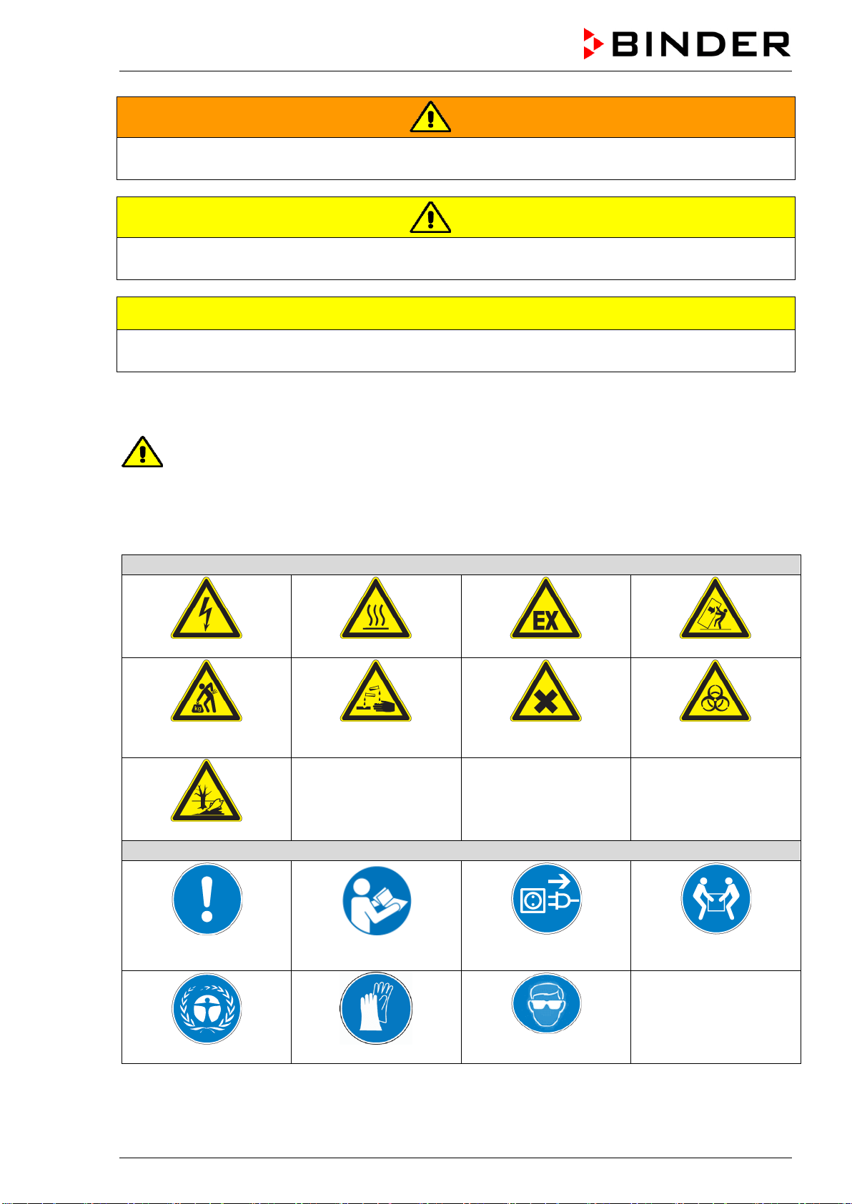
1.2.3 Pictograms
Warning signs
Electrical hazard
Hot surface
Explosive atmosphere
Stability hazard
Lifting hazard
Risk of corrosion and / or
chemical burns
Harmful substances
Biohazard
Pollution Hazard
Mandatory action signs
Mandatory regulation
Read operating
instructions
Disconnect the power
plug
Lift with several persons
Environment protection
Wear protective gloves
Wear safety goggles
BD-S / BD-S-UL, ED-S / ED-S-UL, FD-S / FD-S-UL (E1) 10/2020 page 6/59
Prohibition signs
Do NOT touch
Do NOT spray with
water
Information to be observed in order to ensure optimum function of the product.
1.2.4 Word message panel structure
Type / cause of hazard.
Possible consequences.
∅ Instruction how to avoid the hazard: prohibition.
Instruction how to avoid the hazard: mandatory action.
Observe all other notes and information not necessarily emphasized in the same way, in order to avoid
disruptions that could result in direct or indirect injury or property damage.
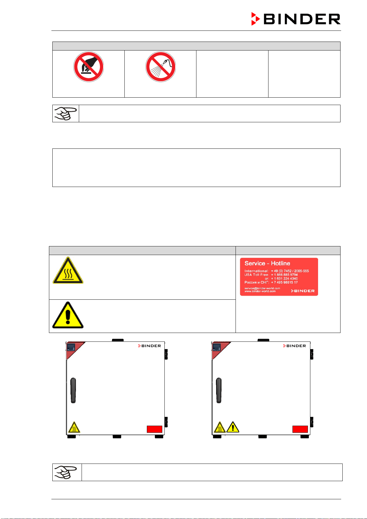
1.3 Localization / position of safety labels on the chamber
The following labels are located on the chamber:
Pictograms (Warning signs)
Service label
Hot surface
• ED-S / ED-S-UL, FD-S / FD-S-UL: outer cham-
ber door
• BD-S / BD-S-UL: on the glass door handle
• On the exhaust air flap
Read operating manual
• UL chamber: outer chamber door
ED-S 56, FD-S 56
ED-S-UL 56, FD-S-UL 56
Figure 1: Position of labels on the chamber front (examples)
Keep safety labels complete and legible.
Replace safety labels that are no longer legible. Contact BINDER Service for these replacements.
BD-S / BD-S-UL, ED-S / ED-S-UL, FD-S / FD-S-UL (E1) 10/2020 page 7/59
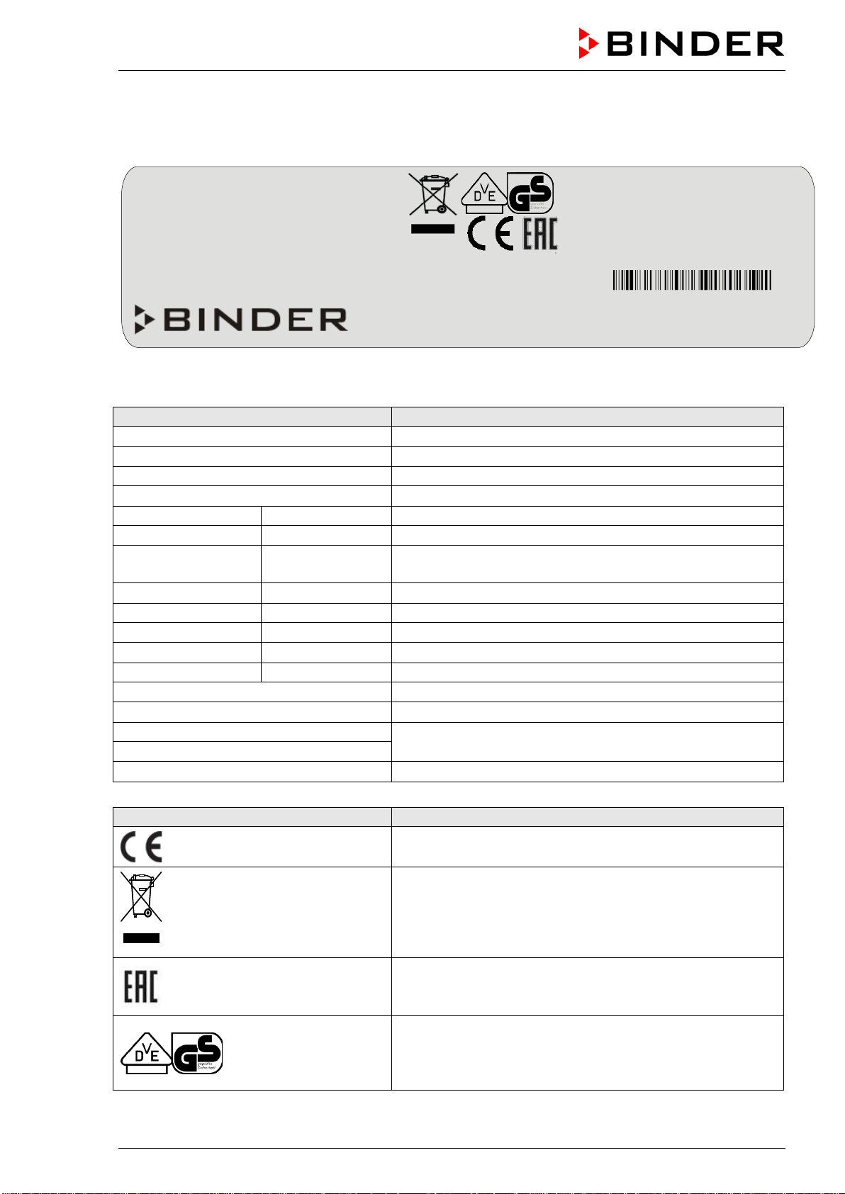
1.4 Type plate
The type plate is located on the left-hand side of the chamber, bottom right-hand.
Figure 2: Type plate (example BD-S 115-230V regular chamber)
Indications of the type plate (example)
Information
BINDER
Manufacturer: BINDER GmbH
BD-S 115
Model designation
Incubator
Chamber name: Incubator
Drying and heating oven
Chamber name: Drying and heating oven
Serial No.
000000000000
Serial No of the chamber
Built
2020
Year of construction
Nominal temperature
70 °C
158 °F
Nominal temperature
IP protection
20
IP type of protection acc. to EN 60529
Temp. safety device
DIN 12880
Temperature safety device acc. to standard DIN 12880
Class
3.1
Class of temperature safety device
Art. No.
9090-0022
Art. no. of the chamber
Project No.
---
Optional: Special application acc. to project no.
1,30 kW
Nominal power
5,7 A
Nominal current
230 V / 50 Hz
Nominal voltage +/- 10%
at the indicated power frequency
230 V / 60 Hz
1 N ~
Current type
Symbol on the type plate
Information
CE conformity marking
Electrical and electronic equipment manufactured / placed
on the market in the EU after 13 August 2005 and to be
disposed of in a separate collection according to Directive
2012/19/EU on waste electrical and electronic equipment
(WEEE).
The chamber is certified according to Customs Union
Technical Regulation (CU TR) for the Eurasian Economic
Union (Russia, Belarus, Armenia, Kazakhstan Kyrgyzstan).
GS mark of conformity of the “VDE Prüf- und Zertifizier-
ungsinstitut” (Testing and Certification Institute of the Asso-
ciation for Electrical, Electronic and Information Technolo-
gies
Nominal temp.
70 °C
0,35 kW / 1,6 A
158 °F
230 V / 50 Hz
IP protection
20
230 V / 60 Hz
Safety device
DIN 12880
1 N ~
Class
3.1
Art. No.
9090-0022
Project No.
Built
2020
Drying and heating oven
BINDER GmbH
Im Mittleren Ösch 5
78532 Tuttlingen / Germany
www.binder-world.com
BD-S 115
E1
Serial No. 00000000000000
Made in Germany
BD-S / BD-S-UL, ED-S / ED-S-UL, FD-S / FD-S-UL (E1) 10/2020 page 8/59
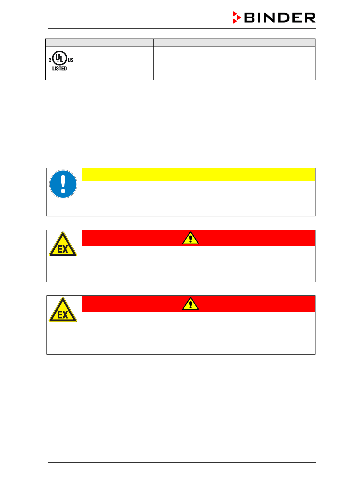
Symbol on the type plate
Information
LABORATORY EQUIPMENT
43KM
(UL chambers
only)
The chamber is certified by Underwriters Laboratories Inc.
®
according to the following standards:
UL 61010-2-10
CAN/CSA-C22.2 No. 61010-2-10
1.5 General safety instructions on installing and operating the chambers
With regard to operating the chambers and to the installation location, please observe the DGUV guide-
lines 213-850 on safe working in laboratories (formerly BGI/GUV-I 850-0, BGR/GUV-R 120 or ZH 1/119,
issued by the employers’ liability insurance association) (for Germany).
BINDER GmbH is only responsible for the safety features of the chamber provided skilled electricians or
qualified personnel authorized by BINDER perform all maintenance and repair, and if components relat-
ing to chamber safety are replaced in the event of failure with original spare parts.
To operate the chamber, use only original BINDER accessories or accessories from third-party suppliers
authorized by BINDER. The user is responsible for any risk caused by using unauthorized accessories.
CAUTION
Danger of overheating.
Damage to the chamber.
∅ Do NOT install the chamber in unventilated recesses.
Ensure sufficient ventilation for dispersal of the heat.
Do not operate the chambers in hazardous locations.
DANGER
Explosion hazard.
Danger of death.
∅ Do NOT operate the chamber in potentially explosive areas.
KEEP explosive dust or air-solvent mixtures AWAY from the chamber.
The chambers do not dispose of any measures of explosion protection.
DANGER
Explosion hazard.
Danger of death.
∅ Do NOT introduce any substance into the chamber which is combustible or explosive at
working temperature.
∅ NO explosive dust or air-solvent mixture in the inner chamber.
Any solvent contained in the charging material must not be explosive or inflammable. I.e., irrespective of
the solvent concentration in the steam room, NO explosive mixture with air must form. The temperature
inside the chamber must lie below the flash point or below the sublimation point of the charging material.
Familiarize yourself with the physical and chemical properties of the charging material, as well as the
contained moisture constituent and its behavior with the addition of heat energy.
Familiarize yourself with any potential health risks caused by the charging material, the contained mois-
ture constituent or by reaction products that may arise during the temperature process. Take adequate
measures to exclude such risks prior to putting the chamber into operation.
BD-S / BD-S-UL, ED-S / ED-S-UL, FD-S / FD-S-UL (E1) 10/2020 page 9/59
DANGER
Electrical hazard.
Danger of death.
∅ The chamber must NOT become wet during operation or maintenance.
The chambers were produced in accordance with VDE regulations and were routinely tested in accord-
ance to VDE 0411-1 (IEC 61010-1).
During and shortly after operation, the temperature of the inner surfaces almost equals the set-point.
CAUTION
The glass doors and glass door handles (BD-S / BD-S-UL), inner chamber, exhaust
air flap, door window (option), and the door gaskets will become hot during opera-
tion.
Danger of burning.
∅ Do NOT touch the glass doors, inner surfaces, exhaust air flap, door window, access
ports, door gaskets, or the charging material during operation.
∅ FD-S / FD-S-UL: Do not place the power cable over the door gap when the chamber is
hot after operation.
1.6 Intended use
The chambers are suitable for exact tempering of harmless materials and for drying and heat treatment of
solid or pulverized charging material, as well as bulk material, using the supply of heat. They can be used
to dry e.g. glassware, and for warm storage of liquids in containers.
Because of their precise temperature accuracy the incubators BD-S / BD-S-UL are especially useful for
incubation of cultures at a standard temperature of 37 °C / 98.6 °F.
A solvent content must not be explosive or flammable. A mixture of any component of the charging mate-
rial with air must NOT be explosive. The operating temperature must lie below the flash point or below the
sublimation point of the charging material. Any component of the charging material must NOT be able to
release toxic gases.
Other applications are not approved.
The chambers are not classified as medical devices as defined by the Medical Device Directive
93/42/EEC.
Do NOT use the chamber for drying processes when large quantities of vapor would form and result in
condensation.
Due to the special demands of the Medical Device Directive 93/42/EEC, these ovens are not
qualified for sterilization of medical devices as defined by the directive.
Observing the instructions in this operating manual and conducting regular maintenance work
(chap. 13) is part of the intended use.
WARNING: If customer should use a BINDER chamber running in non-supervised continu-
ous operation, we strongly recommend in case of inclusion of irrecoverable specimen or
samples to split such specimen or samples and store them in at least two chambers, if this is
feasible.
The charging material shall not contain any corrosive ingredients that may damage the ma-
chine components. Such ingredients include in particular acids and halides. Any corrosive
damage caused by such ingredients is excluded from liability by BINDER GmbH.
BD-S / BD-S-UL, ED-S / ED-S-UL, FD-S / FD-S-UL (E1) 10/2020 page 10/59
The chambers do not dispose of any measures of explosion protection.
DANGER
Explosion or implosion hazard.
Danger of poisoning.
Danger of death.
∅ Do NOT introduce any substance combustible or explosive at working temperature into
the chamber, in particular no energy sources such as batteries or lithium-ion batteries.
∅ NO explosive dust or air-solvent mixture in the inner chamber.
∅ Do NOT introduce any substance which could lead to release of toxic gases.
In case of foreseeable use of the device there is no risk for the user through the integration of the cham-
ber into systems or by special environmental or operating conditions in the sense of EN 61010-1:2010.
For this, the intended use of the chamber and all its connections must be observed.
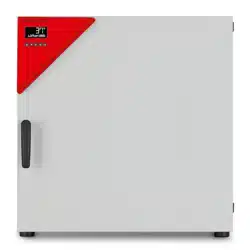
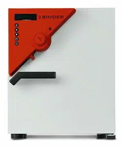
2. Chamber description
BINDER incubators BD-S / BD-S-UL and drying and heating ovens ED-S / ED-S-UL and FD-S / FD-S-UL
are equipped with an electronic PID-controller with digital display.
The incubators BD-S / BD-S-UL indicate the temperature with an accuracy of a tenth of a
degree.
The drying and heating ovens ED-S / ED-S-UL and FD-S / FD-S-UL indicate the temperature
with an accuracy of one degree.
All chambers are heated electrically. Incubators BD-S / BD-S-UL and drying and heating ovens ED-S /
ED-S-UL are ventilated naturally. Drying and heating ovens FD-S / FD-S-UL are ventilated by fan-
assisted, forced-air circulation.
The concept of air conduction guarantees high level of spatial and time-based temperature precision,
thanks to the direct and distributed air circulation into the interior. With FD-S / FD-S-UL, the fan supports
exact attainment and maintenance of the desired temperature accuracy.
The chambers are regularly equipped with an overtemperature safety device class 1 acc. to
DIN12880:2007 and with an overtemperature safety controller (overtemperature temperature safety de-
vice class 2 (ED-S / ED-S-UL, FD-S / FD-S-UL) or class 3.1(BD-S / BD-S-UL) acc. to DIN12880:2007),
see chap. 8.
The inner chamber and the inside of the doors are made of stainless steel V2A (German material no.
1.4016, US equivalent AISI 430). Drying and heating ovens ED-S / ED-S-UL and FD-S / FD-S-UL: When
operating the chambers at temperatures above 150 °C / 302 °F, the impact of the oxygen in the air may
cause discoloration of the metallic surfaces (yellowish-brown or blue) by natural oxidation processes.
These colorations are harmless and will in no way impair the function or quality of the chamber.
All chamber functions are easy and comfortable to use thanks to their clear arrangement. Major features
are easy cleaning of all chamber parts and avoidance of undesired contamination.
Temperature ranges see technical data (chap. 16.4).
BD-S / BD-S-UL, ED-S / ED-S-UL, FD-S / FD-S-UL (E1) 10/2020 page 11/59
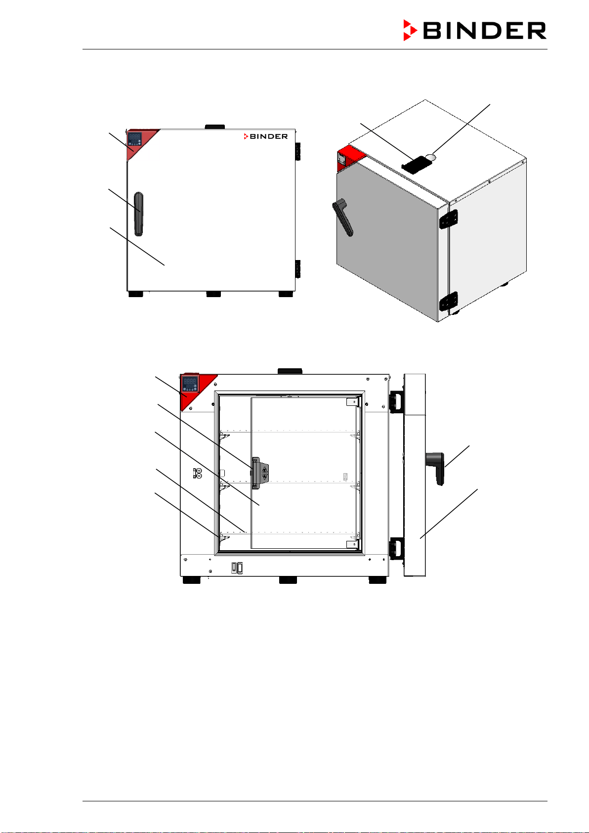
2.1 Chamber overview
Figure 3: Chamber overview, closed chamber
Figure 4: Chamber overview, open chamber with glass door (BD-S / BD-S-UL)
(1) Triangular instrument panel with R-S controller
(2) Outer door
(2a) Outer door handle
(3) Exhaust air outlet
(3a) Exhaust air flap
(4) Glass door (BD-S / BD-S-UL)
(4a) Glass door handle (BD-S / BD-S-UL)
(5) Rack
(5a) Rack support
(4a)
(2)
(5)
(4)
(1)
(2a)
(5a)
(3a)
(3)
(2)
(1)
(2a)
BD-S / BD-S-UL, ED-S / ED-S-UL, FD-S / FD-S-UL (E1) 10/2020 page 12/59
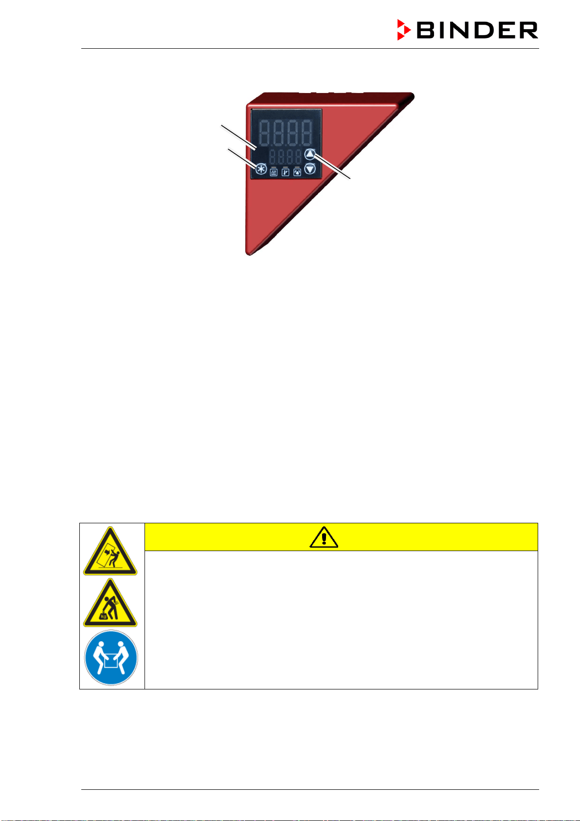
2.2 Triangular instrument panel
Figure 5: Triangular instrument panel with R-S controller
(6) Controller display
(7) Functional controller buttons
3. Completeness of delivery, transportation, storage, and installa-
tion
3.1 Unpacking, and checking equipment and completeness of delivery
After unpacking, please check the chamber and its optional accessories, if any, based on the delivery
receipt for completeness and for transportation damage. Inform the carrier immediately if transportation
damage has occurred.
The final tests of the manufacturer may have caused traces of the racks on the inner surfaces. This has
no impact on the function and performance of the chamber.
Please remove any transportation protection devices and adhesives in/on the chamber and on the doors
and take out the operating manuals and accessory equipment.
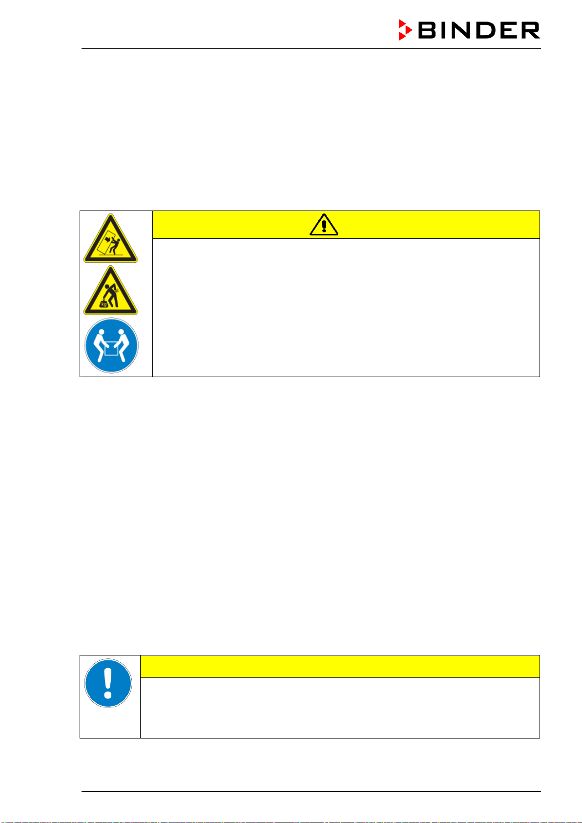
CAUTION
Sliding or tilting of the chamber.
Damage to the chamber.
Risk of injury by lifting heavy loads.
∅ Do NOT lift or transport the chamber using the door handle or the door.
Lift the chamber from the pallet at its four lower corners with the aid of 2 people..
If you need to return the chamber, please use the original packing and observe the guidelines for safe
lifting and transportation (chap. 3.2).
For disposal of the transport packing, see chap. 14.1.
(7)
(6)
(7)
BD-S / BD-S-UL, ED-S / ED-S-UL, FD-S / FD-S-UL (E1) 10/2020 page 13/59
Note on second-hand chambers (Ex-Demo-Units):
Second-hand chambers are chambers that have been used for a short time for tests or exhibitions. They
are thoroughly tested before resale. BINDER ensures that the chamber is technically sound and will work
flawlessly.
Second-hand chambers are marked with a sticker on the chamber door. Please remove the sticker before
commissioning the chamber.
3.2 Guidelines for safe lifting and transportation
After operation please observe the guidelines for temporarily decommissioning the chamber (chap. 14.2).
CAUTION
Sliding or tilting of the chamber.
Damage to the chamber.
Risk of injury by lifting heavy loads.
Transport the chamber only in its original packaging.
Secure the chamber with transport straps for transport.
∅ Do NOT lift or transport the chamber using the door handle or the door.
Lift chamber at its four lower corners with the aid of 2 people, and place it on a
transport pallet with wheels. Push the pallet to the desired site and then lift the
chamber from the pallet at its four lower corners.
• Permissible ambient temperature range during transport: -10 °C to +60 °C / 14 °F to 140 °F.
You can order transport packing and pallets for transportation purposes from BINDER Service.
3.3 Storage
Intermediate storage of the chamber is possible in a closed and dry room. Observe the guidelines for
temporary decommissioning (chap. 14.2).
• Permissible ambient temperature range during storage: -10 °C to +60 °C / 14 °F to 140 °F.
• Permissible ambient humidity: max. 70 % r.h., non-condensing
When after storage in a cold location you transfer the chamber to its warmer installation site, condensa-
tion may form. Before start-up, wait at least one hour until the chamber has attained ambient temperature
and is completely dry.
3.4 Location of installation and ambient conditions
Set up the chamber on an even and non-flammable surface, free from vibration and in a well-ventilated,
dry location and align it using a spirit level. The site of installation must be capable of supporting the
chamber’s weight (see technical data, chap. 16.4). The chambers are designed for setting up inside a
building (indoor use).
CAUTION
Danger of overheating.
Damage to the chamber.
∅ Do NOT set up chambers in non-ventilated recesses.
Ensure sufficient ventilation for dispersal of the heat.
BD-S / BD-S-UL, ED-S / ED-S-UL, FD-S / FD-S-UL (E1) 10/2020 page 14/59
• Permissible ambient temperature range during operation: +18 °C up to +40 °C / 64.4 °F to 104 °F. At
elevated ambient temperature values, fluctuations in temperature can occur.
The ambient temperature should not be substantially higher than the indicated ambient
temperature of +22 °C +/- 3 °C / 71.6 °F ± 5.4 °F to which the specified technical data
relate. For other ambient conditions, deviations from the indicated data are possible.
• Permissible ambient humidity: 70 % r.H. max., non-condensing.
• Installation height: max. 2000 m / 6562 ft. above sea level.
When placing several chambers of the same size side by side, maintain a minimum distance of 250 mm /
9.84 in between each chamber. Wall distances: rear 160 mm / 6.30 in, sides 100 mm / 3.94 in. Spacing
above the chamber of at least 160 mm / 6.30 in must also be accounted for.
The chambers must NOT be stacked.
CAUTION
Danger by stacking.
Damage to the chambers.
∅ Do NOT place chambers on top of each other.
To completely separate the chamber from the power supply, you must disconnect the power plug. Install
the chamber in a way that the power plug is easily accessible and can be easily pulled in case of danger.
For the user there is no risk of temporary overvoltages in the sense of EN 61010-1:2010.
Do not install or operate the chamber in potentially explosive areas.
DANGER
Explosion hazard.
Danger of death.
∅ Do NOT operate the chamber in potentially explosive areas.
KEEP explosive dust or air-solvent mixtures AWAY from the vicinity of the chamber.
4. Installation
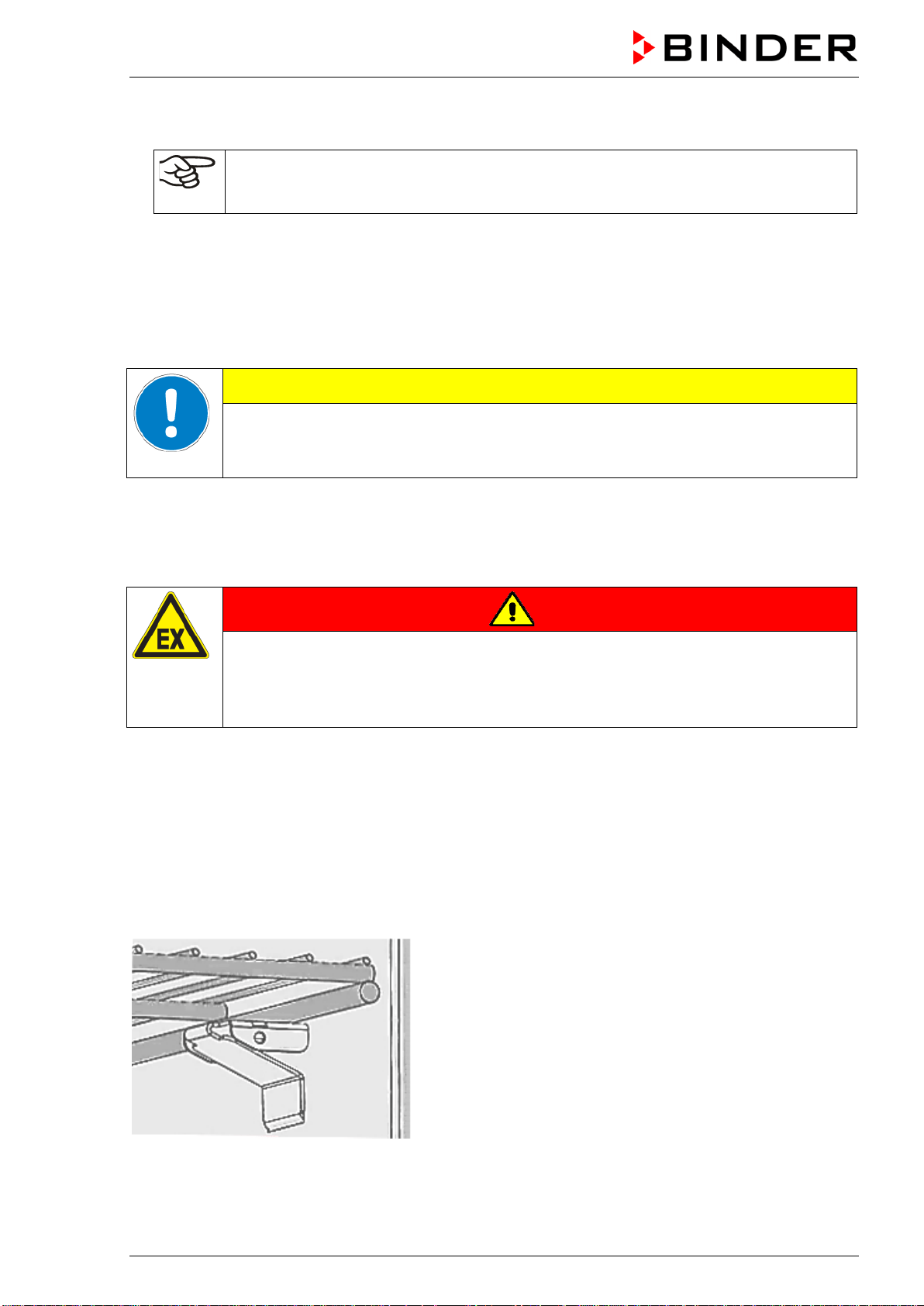
4.1 Installing the racks
Insert 4 rack supports for each rack into the slots of the lateral inner chamber walls. They serve as a sup-
port for the rack.
Figure 6: Rack with rack support
BD-S / BD-S-UL, ED-S / ED-S-UL, FD-S / FD-S-UL (E1) 10/2020 page 15/59
4.2 Connection to an exhaust/ventilation system (optional)
Active suction from the chamber must only be effected together with external air. Therefore, the exhaust
air outlet on the top of the chamber shall not be immediately connected to an active exhaust system.
When connecting to an active exhaust system, proceed as follows:
• Remove the black exhaust air flap.
• Perforate the connecting piece of the exhaust system or place an exhaust air funnel in a distance of 3-
5 cm / 1 to 2 in from the exhaust air outlet. The funnel’s opening must be at least twice as large as the
diameter of the exhaust air outlet.
If improperly connected to an active exhaust/ventilation system, the spatial temperature
exactitude (uniformity), the heating-up and recovering times as well as the maximum tem-
perature of the chamber may be negatively affected.
CAUTION
The exhaust air outlet on the top of the chamber will become hot during operation.
Danger of burning.
∅ Do NOT touch the exhaust air outlet during operation.
4.3 Electrical connection
The chambers are supplied ready for connection and come with an IEC connector plug.
Model Model version
Power plug of
the power
cable
Nominal voltage +/- 10% at
the indicated power frequen-
cy
Current
type
Cham-
ber fuse
BD-S 56 BD-S056-230V Grounded plug
230 V at 50 Hz
230 V at 60 Hz
1N~ 6,3 A
ED-S 56
FD-S 56
ED-S056-230V
FD-S056-230V
Grounded plug
230 V at 50 Hz
230 V at 60 Hz
1N~ 6,3 A
BD-S 115 BD-S115-230V Grounded plug
230 V at 50 Hz
230 V at 60 Hz
1N~ 6,3 A
ED-S 115
FD-S 115
ED-S115-230V
FD-S115-230V
Grounded plug
230 V at 50 Hz
230 V at 60 Hz
1N~ 6,3 A
BD-S-UL 56
BD-S056UL-
120V
NEMA 5-
15P
120 V at 50 Hz
120 V at 60 Hz
1N~ 12,5 A
ED-S-UL 56
FD-S-UL 56
ED-S056UL-
120V
FD-S056UL-120V
NEMA 5-
15P
120 V at 50 Hz
120 V at 60 Hz
1N~ 12,5 A
BD
-S-
UL 115
BD-S115UL-
120V
NEMA 5-
15P
120 V at 50 Hz
120 V at 60 Hz
1N~ 12,5 A
ED
-S-
UL 115
FD-S-UL 115
ED-S115UL-
120V
FD-S115UL-120V
NEMA 5-
15P
120 V at 50 Hz
120 V at 60 Hz
1N~ 12,5 A
• The domestic socket must also provide a protective conductor. Make sure that the connection of the
protective conductor of the domestic installations to the chamber’s protective conductor meets the
latest technology. The protective conductors of the socket and plug must be compatible!
• Prior to connection and start-up, check the power supply voltage. Compare the values to the specified
data located on the chamber’s type plate (left-hand side of the chamber, chap. 1.4).
BD-S / BD-S-UL, ED-S / ED-S-UL, FD-S / FD-S-UL (E1) 10/2020 page 16/59
• When connecting, please observe the regulations specified by the local electricity supply company
and as well as the VDE directives (for Germany). We recommend the use of a residual current circuit
breaker.
• Only use original connection cables from BINDER.
• FD-S / FD-S-UL: Do not place the power cable over the door gap when the chamber is hot after op-
eration.
• Pollution degree (acc. to IEC 61010-1): 2
• Over-voltage category (acc. to IEC 61010-1): II
CAUTION
Danger of incorrect power supply voltage.
Damage to the equipment.
Check the power supply voltage before connection and start-up.
Compare the power supply voltage with the data indicated on the type plate.
See also electrical data (chap. 16.4).
To completely separate the chamber from the power supply, you must disconnect the power
plug. Install the chamber in a way that the power plug is easily accessible and can be easily
pulled in case of danger.
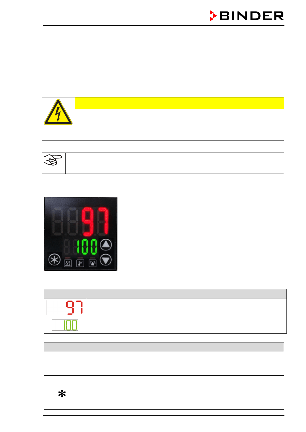
5. R-S controller overview
Figure 7: Normal display (sample values)
Displays of menus or value setting (example)
Upper display (red): Function depending on the menu.
In Normal display: Actual temperature value.
Lower display (green): Function depending on the menu.
In Normal display: Temperature set-point.
Buttons to navigate the manues and enter the values
The arrow buttons serve to navigate and to enter the values
The confirmation button serves to select a menu point and to confirm the entered
value. The confirmation must be made within 60 seconds.
If in Normal display the confirmation button is pressed down for approx. 3 seconds,
the display changes to standby mode (the lower display in Normal display shows
“OFF”).To activate the display, press down the standby button again.

BD-S / BD-S-UL, ED-S / ED-S-UL, FD-S / FD-S-UL (E1) 10/2020 page 17/59
Status-LEDs for information about chamber conditions
Heating active
Safety controller active
Collective alarm
Return to Normal display:
If no entry is made for 120 seconds, the controller returns from each menu to normal display.
To directly return from each menu to normal display, keep pressed down the confirmation button and
press the arrow-up button, if appropriate, several times. Each time you press the arrow-up button the
controller goes back one level.
5.1 Menu structure overview
Normal display
• Temperature set-point entry directly via the confirmation button (chap. 7).
Quick access
Access from Normal display via the arrow buttons:
• Setting the safety controller value (chap. 9.2.1)
• Setting the timer run-time for timer function “Delayed Off” (chap. 10.2.1)
“Setup” menu
The menu is password protected (“S.Loc”). Enter password “10” and select the submenu.
• Setting the temperature unit (chap. 8.1)
“Advanced configuration” menu
The menu is password protected (“A.Loc”). Enter password “20” and select the submenu.
• Setting the ramp gradient (chap. 11.2)
BD-S / BD-S-UL, ED-S / ED-S-UL, FD-S / FD-S-UL (E1) 10/2020 page 18/59
6. Start up
Insert the plug into a suitable socket (chap. 4.2).
If there is no indication on the controller, press the confirmation button until the display lights up.
The controller now shows normal display (chap. 5). If a ramp gradient was active prior to turning off the
chamber, the effective ramp set-point is displayed alternatingly with the target set-point (chap. 11
Warming chambers may release odors in the first few days after commissioning. This is not a
quality defect. To reduce odors quickly we recommend heating up the chamber to its nominal
temperature for one day and in a well-ventilated location.
6.1 Adjusting air change
Opening the black exhaust air flap on top of the chamber serves to adjust the air change.
BD-S / BD-S-UL, ED-S / ED-S-UL: The open exhaust air flap allows increasing fresh air circulation
through the exhaust air outlet.
FD-S / FD-S-UL: The open exhaust air flap and fan operation allow fresh air to come in through the venti-
lation gaps.
Note: If the exhaust air flap is completely open, the spatial temperature accuracy can be negatively influ-
enced.
For connection to an exhaust/ventilation system see chap. 4.2.
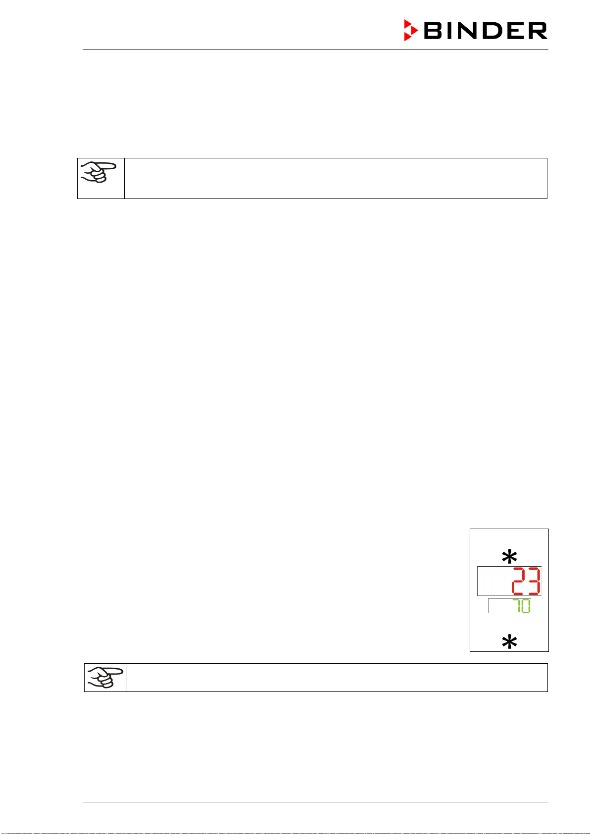
7. Temperature set -point entry
Normal display shows the temperature set-point (lower display) and the actual temperature value (upper
display).
BD-S / BD-S-UL: Setting with an accuracy of a tenth of a degree. Setting range: 0 °C / 31 °F up to 70 °C /
158 °F
ED-S / ED-S-UL, FD-S / FD-S-UL: Setting with an accuracy one degree. Setting range: 0 °C / 31 °F up to
250 °C / 482 °F
Setting:
In Normal display press the confirmation button.
The current temperature set-point (lower display) flashes.
Enter the desired temperature set-point with the arrow buttons and confirm with the
confirmation button.
The controller will now equilibrate to the new temperature set-point.
Example:
or
Check and/or adjust the safety controller following any changes of the set-point (chap. 8).
BD-S / BD-S-UL, ED-S / ED-S-UL, FD-S / FD-S-UL (E1) 10/2020 page 19/59
8. Selecting the temperature unit
You can set the temperature unit to degrees Celsius °C or degrees Fahrenheit °F.
If the unit is changed, all temperature values are converted accordingly.
Also when specifying the ramp function (see chap. 11) this setting is accordingly taken as the basis.
C = degrees Celsius
F= degrees Fahrenheit
0 °C = 31°F
100 °C = 212°F
Conversion:
[Value in °F] = [Value in °C] ∗ 1,8 + 32
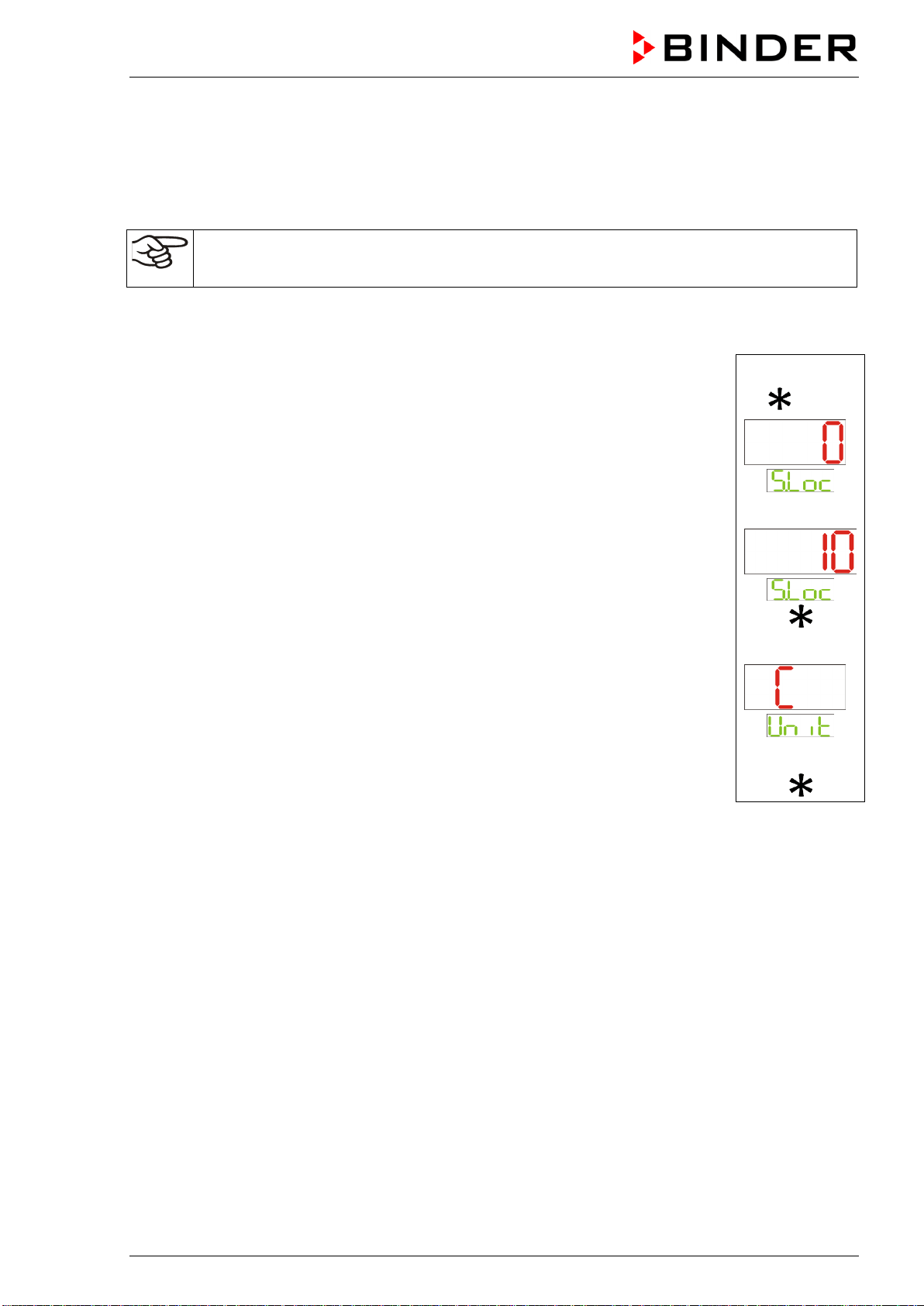
8.1 Setting the temperature unit
Simultaneously press the confirmation button and the arrow-up button to ac-
cess the „Setup“ menu. The password entry display “S.Loc” flashes.
Press the arrow-up button to access the “Unit“ menu (temperature unit). The
„Unit“ menu is shown with the current temperature unit.
Press the confirmation button to activate the entry. The display “Unit” flashes.
Select the desired unit with the arrow buttons and confirm with the confirmation
button.
Keep pressed down the confirmation button and press the arrow-up button to
return to Normal display.
Example:
+
10x
or
9. Overtemperature protection
9.1 Overtemperature protective device (class 1)
The chambers are equipped with an internal temperature safety device, class 1 acc. to DIN 12880:2007.
It serves to protect the unit and prevents dangerous conditions caused by major defects.
If the cut-off temperature is reached, the over temperature protective device permanently turns off the
unit. The user cannot restart the device again. The protective cut-off device is located internally. Only a
service specialist can replace it. Therefore, please contact an authorized service provider or BINDER
service.
Cut-off temperature values:
BD-S / BD-S-UL: 90 °C / 194 °F
ED-S / ED-S-UL, FD-S / FD-S-UL: 318 °C / 604.4 °F
BD-S / BD-S-UL, ED-S / ED-S-UL, FD-S / FD-S-UL (E1) 10/2020 page 20/59
9.2 Safety controller
The chambers are regularly equipped with an adjustable electronic safety controller. It serves to protect
the chamber, its environment and the contents against exceeding the maximum permissible temperature.
Please observe the DGUV guidelines 213-850 on safe working in laboratories (formerly BGI/GUV-I 850-0,
BGR/GUV-R 120 or ZH 1/119, issued by the employers’ liability insurance association) (for Germany).
Depending on the chamber type the safety controller acts as an over temperature safety device class 2
(“temperature limiter”) or class 3.1 (“temperature protection”) acc. to DIN 12880:2007.
Check the setting regularly and adjust it following any changes of the set-point.
• BD-S / BD-S-UL: Safety controller class 3.1
The safety controller class 3.1 limits the temperature inside the chamber to the entered safety control-
ler set-point. In the event of a fault (if this maximum temperature is exceeded), it takes over the control
to this value. This status is reported visually by an alarm message.
The safety controller keeps control of the chamber until the chamber temperature cools down below
the safety controller set-point value.
• ED-S / ED-S-UL, FD-S / FD-S-UL: Safety controller class 2
The safety controller class 2 limits the temperature inside the chamber to the entered safety controller
set-point. In the event of a fault (if this maximum temperature is exceeded) the safety controller com-
pletely turns off the heating until manual reset. This status is reported visually by an alarm message.
Function check:
Check the safety controller at appropriate intervals for its functionality. It is recommended that the author-
ized operating personnel should perform such a check, e.g., before starting a longer work procedure.
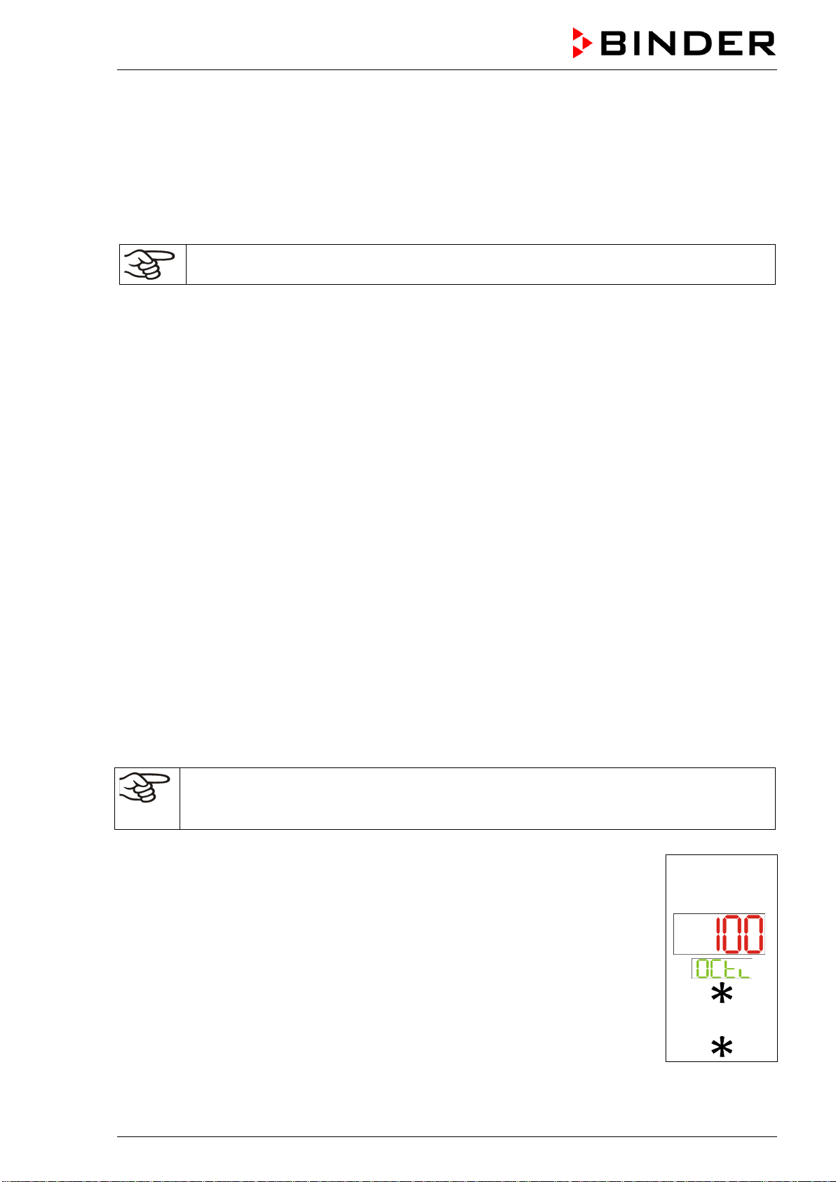
9.2.1 Setting the safety controller
A limit temperature is entered as the safety controller set-point , i.e. the absolute maximum permitted
temperature value.
BD-S / BD-S-UL: Setting with an accuracy of a tenth of a degree. 0 °C / 31 °F up to 80 °C / 176 °F
ED-S / ED-S-UL, FD-S / FD-S-UL: Setting with an accuracy one degree. 0 °C / 31 °F up to 260 °C /
500 °F
Regularly check the safety controller setting relating to the entered temperature set-point
Set the safety controller set-point by approx. 2 °C to 5 °C above the desired temperature set-
point.
Setting:
In Normal display press the arrow-up button to access the “OCtl” (safety control-
ler) setting menu.
The current safety controller value is shown (upper display)
Press the confirmation button. The display “OCtl” flashes.
Enter the desired safety controller value with the arrow buttons and confirm with
confirmation button.
The new safety controller value is activated.
Press the arrow-down button to return to Normal display.
Example:
or
BD-S / BD-S-UL, ED-S / ED-S-UL, FD-S / FD-S-UL (E1) 10/2020 page 21/59
9.2.2 Alarm message and proceeding in case of an alarm
The status LED “Heating active” is lit.
• BD-S / BD-S-UL: Safety controller class 3.1
The safety controller keeps control of the chamber until the chamber temperature cools down below
the entered safety controller value. First the heating turns off. As soon as the inner chamber tempera-
ture has cooled down below the safety controller set-point, the heating is released and temperature
control is resumed by the controller.
If the safety controller class 3.1 has repeatedly taken over control, we recommend proceeding as fol-
lows:
• Disconnect the chamber from the power supply.
• Have an expert examine and rectify the cause of the fault.
• Restart the chamber
• ED-S / ED-S-UL, FD-S / FD-S-UL: Safety controller class 2
The heating turns off.
As soon as the inner chamber temperature has cooled down below the safety controller value, you
can reset the alarm message on the controller. Press the confirmation button. The heating is then
released and temperature control is resumed by the controller. The status LED “Heating active” is off.
If the safety controller class 2 has turned off the heating, we recommend proceeding as follows:
• Disconnect the chamber from the power supply.
• Have an expert examine and rectify the cause of the fault.
• Restart the chamber
• Reset the alarm message with the confirmation button
10. Timer function “Delayed Off”
The chambers offer the timer function “Delayed Off”.
This function serves to set a delay time until the control is turned off.
The selected timer run-time immediately starts running down.
When the timer expires, control deactivates (standby mode), heating and fan (with FD-S / FD-S-UL) turn
off. The lower display in Normal display shows “OFF”.
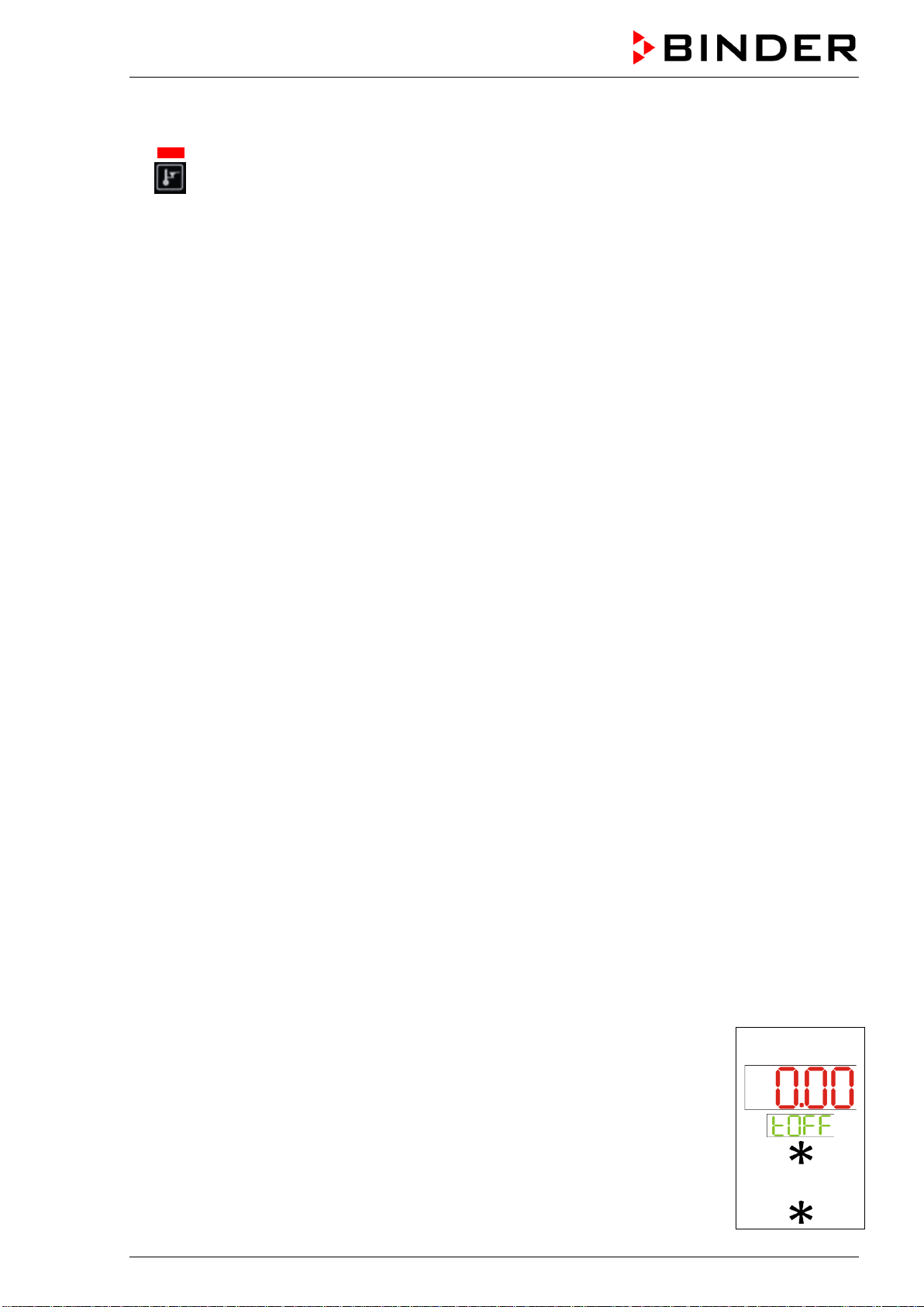
10.1 Setting the timer run-time
In Normal display press the arrow-down button to access the “tOFF” entry menu.
The current timer run-time [hh.mm] is displayed (upper display)
Press the confirmation button to activate the entry. The display “tOFF” flashes.
Set the desired timer run-time with the arrow buttons and confirm with the con-
firmation button.
Press the arrow-down button to return to Normal display.
or
BD-S / BD-S-UL, ED-S / ED-S-UL, FD-S / FD-S-UL (E1) 10/2020 page 22/59
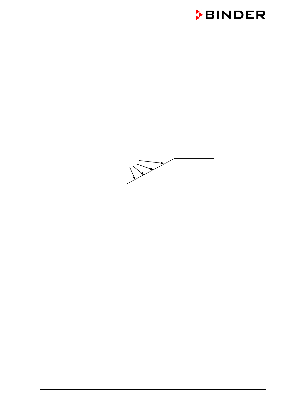
11. Ramp function
You can program temperature ramps in order to extend heating up times. This may be necessary in some
cases to prevent temperature stress in the material during the heating up phase. Temperature ramps
should only be used if required. Using them may result in considerably slowing down the heating up
times. When the ramp function is turned off, the chamber will heat up with its maximum heating capacity.
The desired temperature rise is entered as a set-point gradient in degrees per hour. This gradient limits
the maximum temperature increase to the entered value. Due to the heat and evaporation energy as-
sumed by the drying material, smaller temperature gradients may also result.
You can select a gradient from “0.001” up to “9999” degrees per hour. The chamber will try to heat up
according to the entered gradient. A heating-up rate of 24 °C per hour for the incubators BD-S / BD-S-UL
and of 240 °C per hour for the heating and drying ovens ED-S / ED-S-UL and FD-S / FD-S-UL can be
regarded as a realistic maximum.
The ramp proceeds from the actual value (equilibrated start set-point) towards the entered target set-
point. During ramp operation the effective ramp set-point (SPr) continually rises in accordance to the en-
tered gradient from the start set-point to the target set-point. The actual value follows this continually
changing effective ramp set-point. As soon as the entered target set-point (ramp target temperature) is
reached, this value is maintained constant.
Figure 8: Set-point types during ramp operation
11.1 Setting the ramp
1. Enter the start set-point of the ramp (chap. 7) and let the temperature equilibrate to this value.
2. Set the desired gradient in the „rAtE“ menu
Setting „0.001“ up to „9999“: Maximum temperature rise in °C per hour or °F per hour.
Setting „Off“: deactivated ramp function. The chamber will heat up with its maximum heating capacity.
3. Then enter a new set-point as the ramp’s target set-point (chap. 7).
As soon as the entries have been adopted, the ramp function is activated. The chamber heats up with the
entered gradient, as long as the entered set-point (SP) exceeds the actual temperature value.
Start set-point
Effective ramp set-point
SPr
Target set-point
SP

BD-S / BD-S-UL, ED-S / ED-S-UL, FD-S / FD-S-UL (E1) 10/2020 page 23/59
11.2 Setting the gradient
Simultaneously press the confirmation button and the arrow-down button to
access the “Advanced configuration” menu. The password entry display “A.Loc”
flashes.
Press the arrow-up button to access the “SPti” menu. Press the confirmation
button to select the menu.
Press the arrow-up button to access the “rAtE” (ramp gradient) submenu. The
“rAtE” submenu is shown with the current setting.
Press the confirmation button to activate the entry. The display “rAtE” flashes.
Set the desired gradient with the arrow buttons and confirm with the confirmation
button.
Keep pressed down the confirmation button and press the arrow-up button
several times to return to Normal display.
Example:
+
20 x
5 x
or
11.3 Display of the ramp course
In normal display the target set-point and the effective ramp set-point are shown alternatingly in the lower
display.
11.4 Turning off the ramp function
To turn off the ramp function, the gradient must be set to “Off” in the “rAtE” menu (chap. 11.2).

BD-S / BD-S-UL, ED-S / ED-S-UL, FD-S / FD-S-UL (E1) 10/2020 page 24/59
12. Options
12.1 Data logger kits (option)
BINDER Data Logger Kits offer an independent long-term measuring system for temperature. They are
equipped with a keyboard and a large LCD display, alarm functions and a real-time function. Measure-
ment data are recorded in the Data Logger and can be read out after the measurement via the RS232
interface of the Data Logger. It offers a programmable measuring interval and permits storing up to 64000
measuring values. Reading out is done with the Data Logger evaluation software. You can give out a
combined alarm and status protocol directly to a serial printer.
BD-S / BD-S-UL: Data Logger Kit T 220. Temperature range -90 °C / -130 °F up to +220 °C / 428 °F
ED-S / ED-S-UL, FD-S / FD-S-UL: Data Logger Kit T 350. Temperature range 0 °C / 32 °F up to +350 °C
/ 662 °F
For detailed information on installation and operation of the BINDER Data Logger, please
refer to the mounting instructions Art. No. 7001-0204 and to the original user manual of the
manufacturer, supplied with the data logger.
13. Maintenance, cleaning, and service
13.1 Maintenance intervals, service
DANGER
Electrical hazard.
Danger of death.
∅ The chamber must NOT become wet during operation or maintenance work.
∅ Do NOT remove the rear panel of the chamber.
Disconnect the chamber before conducting maintenance work. Disconnect the power
plug.
Ensure all maintenance work is conducted by licensed electricians or experts author-
ized by BINDER.
Ensure regular maintenance work is performed at least once a year.
The warranty becomes void if maintenance work is conducted by non-authorized personnel..
Replace the door gasket only when cold. Otherwise, the door gasket may become damaged.
We recommend taking out a maintenance agreement. Please consult BINDER Service.
BINDER telephone hotline: +49 (0) 7462 2005 555
BINDER fax hotline: +49 (0) 7462 2005 93555
BINDER e-mail hotline: service@binder-world.com
BINDER service hotline USA: +1 866 885 9794 or +1 631 224 4340 x3 (toll-free in the USA)
BINDER service hotline Asia Pacific: +852 390 705 04 or +852 390 705 03
BINDER service hotline Russia and CIS +7 495 988 15 16
BINDER Internet website http://www.binder-world.com
BINDER address BINDER GmbH, post office box 102, D-78502 Tuttlingen
International customers, please contact your local BINDER distributor.
BD-S / BD-S-UL, ED-S / ED-S-UL, FD-S / FD-S-UL (E1) 10/2020 page 25/59
13.2 Cleaning and decontamination
Clean the chamber after each use to avoid potential corrosion damage by ingredients of the test material.
DANGER
Electrical hazard.
Danger of death.
∅ Do NOT spill water or cleaning agents over the inner and outer surfaces.
Disconnect the chamber before cleaning. Disconnect the power plug.
Completely dry the chamber before turning it on again.
13.2.1 Cleaning
Disconnect the chamber from the power supply before cleaning. Disconnect the power plug.
The interior of the chamber must be kept clean. Thoroughly remove any residues of the charg-
ing material
Wipe the surfaces with a moistened towel. In addition, you can use the following cleaning agents:
Exterior surfaces
inner chamber
racks
door gaskets
Standard commercial cleaning detergents free from acid or halides.
Alcohol-based solutions.
We recommend using the neutral cleaning agent Art. No. 1002-0016.
Instrument panel Standard commercial cleaning detergents free from acid or halides.
We recommend using the neutral cleaning agent Art. No. 1002-0016.
Zinc coated hinge parts
rear chamber wall
Standard commercial cleaning detergents free from acid or halides.
Do NOT use a neutral cleaning agent on zinc coated surfaces.
Do not use cleaning agents that may cause a hazard due to reaction with components of the device or
the charging material. If there is doubt regarding the suitability of cleaning products, please contact
BINDER service.
We recommend using the neutral cleaning agent Art. No. 1002-0016 for a thorough cleaning.
Any corrosive damage that may arise following use of other cleaning agents is excluded from
liability by BINDER GmbH.
Any corrosive damage caused by a lack of cleaning, is excluded from liability by BINDER
GmbH.
CAUTION
Danger of corrosion.
Damage to the chamber.
∅ Do NOT use acidic or chlorine cleaning detergents.
∅ Do NOT use a neutral cleaning agent on other kind of surfaces e.g., the zinc coated
hinge parts or the rear chamber wall.
For surface protection, perform cleaning as quickly as possible.
After cleaning completely remove cleaning agents from the surfaces with a moistened towel.
Let the chamber dry.

BD-S / BD-S-UL, ED-S / ED-S-UL, FD-S / FD-S-UL (E1) 10/2020 page 26/59
Soapsuds may contain chlorides and must therefore NOT be used for cleaning.
With every decontamination method, always use adequate personal safety controls.
Following cleaning, leave the chamber door open or remove the access port plugs.
The neutral cleaning agent may cause health problems in contact with skin and if ingested.
Follow the operating instructions and safety hints labeled on the bottle of the neutral clean-
ing agent.
Recommended precautions: To protect the eyes use sealed protective goggles. Suitable protective
gloves with full contact: butyl or nitrile rubber, penetration time >480 minutes.
CAUTION
Contact with skin, ingestion.
Skin and eye damage due to chemical burns.
∅ Do not ingest. Keep away from food and beverages.
∅ Do NOT empty into drains.
Wear protective gloves and goggles.
Avoid skin contact.
13.2.2 Decontamination
The operator must ensure that proper decontamination is performed in case a contamination of the
chamber by hazardous substances has occurred.
Disconnect the chamber from the power supply prior to decontamination. Pull the power plug.
Do not use decontamination agents that may cause a hazard due to reaction with components of the
device or the charging material. If there is doubt regarding the suitability of cleaning products, please
contact BINDER service.
You can use the following disinfectants:
Inner chamber Standard commercial surface disinfectants free from acid or halides.
Alcohol-based solutions.
We recommend using the disinfectant spray Art. No. 1002-0022.
For chemical disinfection, we recommend using the disinfectant spray Art. No. 1002-0022.
Any corrosive damage that may arise following use of other disinfectants is excluded from
liability by BINDER GmbH.
With every decontamination method, always use adequate personal safety controls.
In case of impurity of the interior with biological or chemical hazardous material, there are three possible
procedures depending on the type of contamination and of the charging material.
1. The drying and heating ovens ED-S / ED-S-UL and FD-S / FD-S-UL can be hot air sterilized at 190 °C
/ 374 °F for at least 30 minutes. All inflammable goods must be removed from the interior before.
BD-S / BD-S-UL, ED-S / ED-S-UL, FD-S / FD-S-UL (E1) 10/2020 page 27/59
2. Spray the inner chamber with an appropriate disinfectant.
Before start-up, the chamber must be absolute dry and ventilated, because explosive gases may form
during the decontamination process.
3. You can remove the racks and the rack supports from the chamber and sterilize them
In case of eye contact, the disinfectant spray may cause eye damage due to chemical
burns. Follow the operating instructions and safety hints labeled on the bottle of the disin-
fectant spray.
Recommended precautions: To protect the eyes use sealed protective goggles.
CAUTION
Eye contact.
Eye damage due to chemical burns.
∅ Do NOT empty into drains.
Wear protective goggles.
After using the disinfectant spray, allow the chamber to dry thoroughly, and aerate it sufficient-
ly.
13.3 Sending the chamber back to BINDER GmbH
If you return a BINDER product to us for repair or any other reason, we will only accept the product upon
presentation of an authorization number (RMA number) that has previously been issued to you. An
authorization number will be issued after receiving your complaint either in writing or by telephone prior
to your sending the BINDER product back to us. The authorization number will be issued following receipt
of the information below:
• BINDER product type and serial number
• Date of purchase
• Name and address of the dealer from which you bought the BINDER product
• Exact description of the defect or fault
• Complete address, contact person and availability of that person
• Exact location of the BINDER product in your facility
• A contamination clearance certificate (chap. 19) must be faxed in advance
The authorization number must be applied to the packaging in such a way that it can be easily recognized
or be recorded clearly in the delivery documents.
For safety reasons we cannot accept a chamber delivery if it does not carry an authorization
number.
Return address:
BINDER GmbH, Abteilung Service
Gänsäcker 16, 78502 Tuttlingen, Germany
BD-S / BD-S-UL, ED-S / ED-S-UL, FD-S / FD-S-UL (E1) 10/2020 page 28/59
14. Disposal
14.1 Disposal of the transport packing
Packing element
Material
Disposal
Straps to fix packing on pallet
Plastic
Plastic recycling
Wooden transport box (option)
with metal screws
Non-wood (compressed match-
wood, IPPC standard)
Wood recycling
Metal
Metal recycling
Pallet (size 115)
Solid wood (IPPC standard)
Wood recycling
Transport box
with metal clamps
Cardboard
Paper recycling
Metal
Metal recycling
Edge protection
Styropor
®
or PE foam
Plastic recycling
Protection of doors and racks
PE foam
Plastic recycling
Bag for operating manual
PE foil
Plastic recycling
Insulating air cushion foil (packing of
optional accessories)
PE foil Plastic recycling
If recycling is not possible, all packing parts can also be disposed of with normal waste.
14.2 Decommissioning
• Disconnect the chamber from the power supply (pull the power plug).
• Temporal decommissioning: See indications for appropriate storage, chap. 3.3.
• Final decommissioning: Dispose of the chamber as described in chap. 14.3 to 14.5.
14.3 Disposal of the chamber in the Federal Republic of Germany
According to Annex I of Directive 2012/19/EU of the European Parliament and of the Council on waste
electrical and electronic equipment (WEEE), BINDER devices are classified as “monitoring and control
instruments” (category 9) only intended for professional use“. They must not be disposed of at public col-
lecting points.
The chambers bear the symbol for the marking of electrical and electronic equipment man-
ufactured / placed on the market in the EC after 13 August 2005 and be disposed of in sep-
arate collection according to Directive 2012/19/EU on waste electrical and electronic
equipment (WEEE) and German national law for electrical and electronic equipment (El-
ektro- und Elektronikgerätegesetz, ElektroG). WEEE marking: crossed-out wheeled bin with
solid bar under. A significant part of the materials must be recycled in order to protect the
environment.
At the end of the device’s service life, have the device disposed of according to the German national law
for electrical and electronic equipment (Elektro- und Elektronikgerätegesetz, ElektroG from 20 October
2015, BGBl. I p. 1739) or contact BINDER service who will organize taking back and disposal of the
chamber according to the German national law for electrical and electronic equipment (Elektro- und El-
ektronikgerätegesetz, ElektroG from 20 October 2015, BGBl. I p. 1739).

BD-S / BD-S-UL, ED-S / ED-S-UL, FD-S / FD-S-UL (E1) 10/2020 page 29/59
CAUTION
Violation against existing law.
∅ Do NOT dispose of BINDER devices at public collecting points.
Have the device disposed of professionally at a recycling company which is certified
according to the German national law for electrical and electronic equipment (Elektro-
und Elektronikgerätegesetz, ElektroG from 20 October 2015, BGBl. I p. 1739).
or
Instruct BINDER Service to dispose of the device. The general terms of payment and
delivery of BINDER GmbH apply, which were valid at the time of purchasing the cham-
ber.
Certified companies disassemble waste BINDER equipment in primary substances for recycling accord-
ing to Directive 2012/19/EU. In order to eliminate any health hazards to the employees of the recycling
companies, the devices must be free from toxic, infectious or radioactive substances.
Prior to handing the chamber over to a recycling company, it is the user’s responsibility that it
is free from toxic, infectious or radioactive substances.
• Prior to disposal, clean all introduced or residual toxic substances from the chamber.
• Prior to disposal, disinfect the chamber
from all sources of infection. Be aware of the fact
that sources of infection may also be located outside the inner chamber.
• If you cannot safely remove all toxic substances and sources of infection from the cham-
ber, dispose of it as “special” waste according to national law.
• Fill out the contamination clearance certificate (chap. 19) and enclose it with the chamber.
WARNING
Contamination of the device with toxic, infectious or radioactive substances.
Danger of intoxication.
Danger of infection.
∅ NEVER take a chamber contaminated with toxic substances or sources of infection for
recycling according to Directive 2012/19/EU.
Prior to disposal, remove all toxic substances and sources of infection from the cham-
ber.
Dispose of a chamber from which all toxic substances or sources of infection cannot be
safely removed as special waste according to national law.
14.4 Disposal of the chamber in the member states of the EU except for the Fed-
eral Republic of Germany
According to Annex I of Directive 2012/19/EU of the European Parliament and of the Council on waste
electrical and electronic equipment (WEEE), BINDER devices are classified as “monitoring and control
instruments” (category 9) only intended for professional use“. They must not be disposed of at public col-
lecting points.
The chambers bear the symbol for the marking of electrical and electronic equipment man-
ufactured / placed on the market in the EC after 13 August 2005 and be disposed of in sep-
arate collection according to the Directive 2012/19/EU on waste electrical and electronic
equipment (WEEE). WEEE marking: crossed-out wheeled bin with solid bar under.
At the end of the device’s service life, notify the distributor who sold you the device, who will take back
and dispose of the chamber according to the Directive 2012/19/EU on waste electrical and electronic
equipment (WEEE).
BD-S / BD-S-UL, ED-S / ED-S-UL, FD-S / FD-S-UL (E1) 10/2020 page 30/59
CAUTION
Violation against existing law.
∅ Do NOT dispose of BINDER devices at public collecting points.
Have the device disposed of professionally at a recycling company which is certified
according to conversion of the Directive 2012/19/EU into national law.
or
Instruct the distributor who sold you the device to dispose of it. The agreements apply
that were reached with the distributor when purchasing the chamber (e.g. his general
terms of payment and delivery).
If your distributor is not able to take back and dispose of the chamber, please contact
BINDER service.
Certified companies disassemble waste BINDER equipment in primary substances for recycling accord-
ing to Directive 2012/19/EU. In order to exclude any health hazard for the employees of the recycling
companies, the devices must be free from toxic, infectious or radioactive substances.
Prior to handing the chamber over to a recycling company, it is the user’s responsibility that it
is free from toxic, infectious or radioactive substances.
• Prior to disposal, clean all introduced or residual toxic substances from the chamber.
• Prior to disposal, disinfect the chamber
from all sources of infection. Be aware of the fact
that sources of infection may also be located outside the inner chamber.
• If you cannot safely remove all sources of infection and toxic substances from the cham-
ber, dispose of it as “special” waste according to national law.
• Fill out the contamination clearance certificate (chap. 19) and enclose it with the chamber.
WARNING
Contamination of the device with toxic, infectious or radioactive substances.
Danger of intoxication.
Danger of infection.
∅ NEVER take a chamber contaminated with toxic substances or sources of infection for
recycling according to Directive 2012/19/EU.
Prior to disposal, remove all toxic substances and sources of infection from the cham-
ber.
Dispose of a chamber from which all toxic substances or sources of infection cannot be
safely removed as “special” waste according to national law.
14.5 Disposal of the chamber in non-member states of the EU
CAUTION
Alteration of the environment.
For final decommissioning and disposal of the chamber, please contact BINDER Ser-
vice.
Follow the statutory regulations for appropriate, environmentally friendly disposal.
BD-S / BD-S-UL, ED-S / ED-S-UL, FD-S / FD-S-UL (E1) 10/2020 page 31/59
15. Troubleshooting
Fault description
Possible cause
Required measures
Chamber without function. Con-
troller display is dark.
No power supply.
Check connection to power supply.
Overtemperature protective
device class 1 has turned off
the chamber.
Contact BINDER service.
Controller defective.
Contact BINDER service.
Chamber without function. Con-
troller shows “OFF” on lower
display and actual temperature
value on upper display.
Chamber in standby mode. Press the confirmation button.
Set-point temperature is not
reached after specified time.
Chamber door not properly
closed.
Completely close chamber door.
Door gasket defective.
Replace door gasket,
Controller not adjusted.
Calibrate and adjust controller.
Wrong voltage.
Check the power supply for correct
voltage (chap. 4.2).
FD-S / FD-S-UL:
The fan doesn’t turn or turns too
slowly.
Fan defective. Contact BINDER service.
Chamber heating permanently,
set-point not held.
Controller defective.
Contact BINDER service.
Pt 100 sensor defective.
Semiconductor relay defective
Controller not adjusted.
Calibrate and adjust controller.
Chamber doesn’t heat up. Status
LED “Heating active” is lit.
Heating element defective.
Contact BINDER service.
Semiconductor relay defective.
Chamber doesn’t heat up. Status
LED “Heating active” is not lit.
Controller display working.
Timer run off.
Re-program the timer or turn it off.
Semiconductor relay defective.
Contact BINDER service.
Controller defective.
Chamber doesn’t heat up. Status
LED “Safety controller active” is
lit.
BD-S / BD-S-UL:
Safety controller class 3.1 has
responded.
Check the settings of the tempera-
ture set-point and of the safety con-
troller. If appropriate, select suitable
limit value. See chap. 9.2.
ED-S / ED-S-UL, FD-S / FD-S-
UL:
Safety controller class 2 has
turned off the heating.
Let cool down the chamber. Press
the confirmation button (chap.
9.2.2). Check the settings of the
temperature set-point and of the
safety controller. If appropriate, se-
lect suitable limit value.
Safety controller defective.
Contact BINDER service.
Deviations from the indicated
heating-up times.
Chamber fully loaded.
Load the chamber less or consider
longer heating-up times.
Controller shows “OFF” on lower
display and “OPEN” on upper
display.
Sensor rupture between sen-
sor and controller.
Contact BINDER service.
Only qualified service personnel authorized by BINDER must perform repair.
Repaired chambers must comply with the BINDER quality standards.
BD-S / BD-S-UL, ED-S / ED-S-UL, FD-S / FD-S-UL (E1) 10/2020 page 32/59
16. Technical description
16.1 Factory calibration and adjustment
This chamber was calibrated and adjusted in the factory. Calibration and adjustment were performed
using standardized test instructions, according to the QM DIN EN ISO 9001 system applied by BINDER
(certified since December 1996 by TÜV CERT). All test equipment used is subject to the administration of
measurement and test equipment that is also constituent part of the BINDER QM DIN EN ISO 9001 sys-
tems. They are controlled and calibrated to a DKD-Standard at regular intervals.
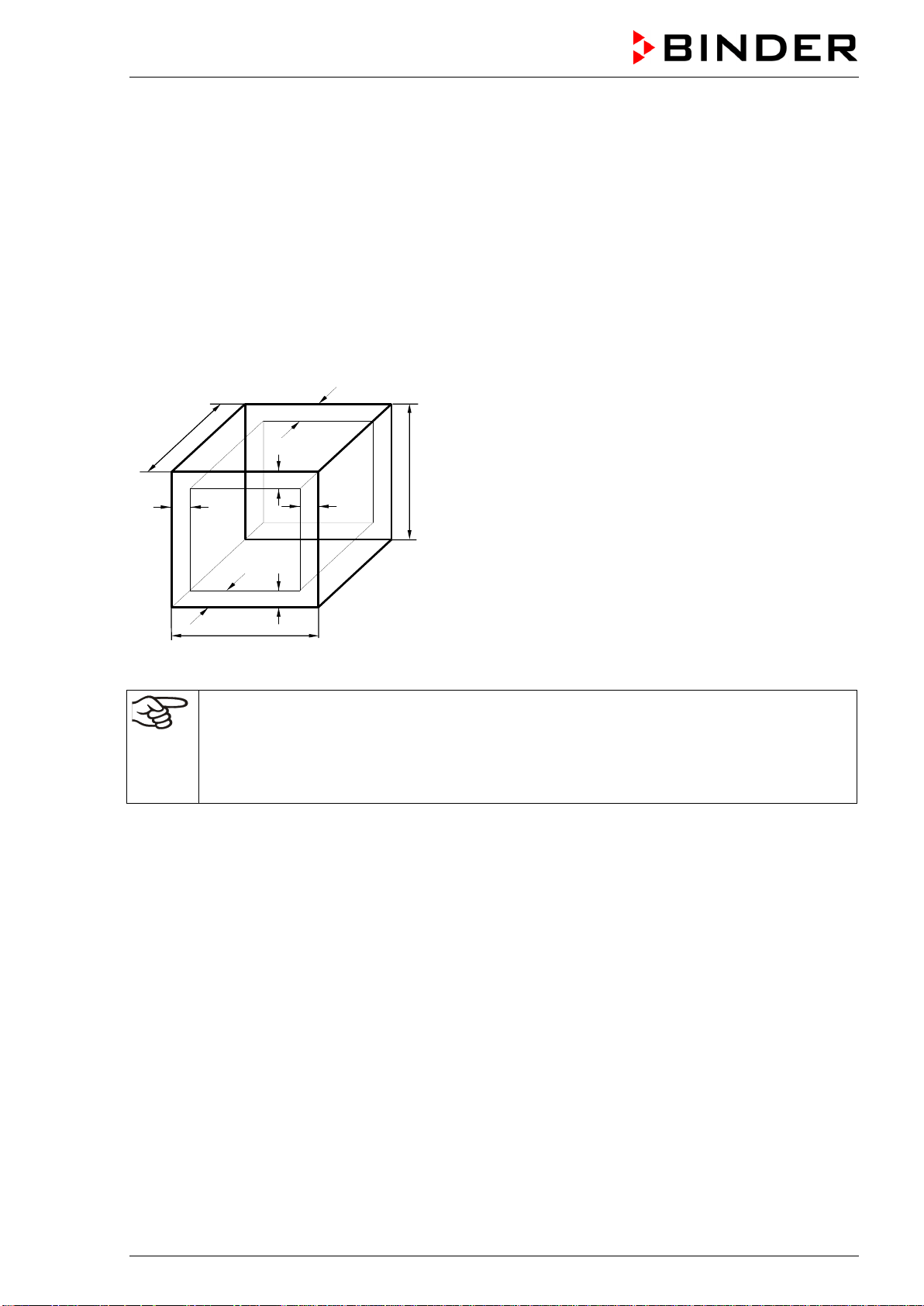
16.2 Definition of usable volume
The usable volume illustrated below is calculated as follows:
c
c
b
a
C
B
A
b
a
A, B, C = Internal dimensions (W, H, D)
a, b, c = Wall clearances
a = 0.1 x A
b = 0.1x B
c = 0.1 x C
V
USE
= (A - 2a) x (B - 2b) x (C - 2c)
Figure 9: Determination of the useable volume
The technical data refers to the defined usable volume.
Do NOT place samples outside this usable volume.
Do NOT load this volume by more than half to enable sufficient airflow inside the chamber.
Do NOT divide the usable volume into separate parts with large area samples.
Do NOT place samples too close to each other in order to permit circulation between them
and thus obtain a homogenous distribution of temperature.
16.3 Over current protection
The chambers are protected by one (UL chambers) or two miniature fuses against over current, accessi-
ble from the outside. The miniature fuses are located at the rear of the chamber above the power cable
connection. Each fuse holder is equipped with a fuse clip 5mm x 20 mm (cUL-Version 6,3x32 mm). A
fuse may be replaced only with a substitute of the same ratings. Refer to the technical data of the respec-
tive device type.
BD-S / BD-S-UL, ED-S / ED-S-UL, FD-S / FD-S-UL (E1) 10/2020 page 33/59
16.4 Technical data
Model
BD-S
BD-S-UL
ED-S
ED-S-UL
FD-S
FD-S-UL
BD-S
BD-S-UL
ED-S
ED-S-UL
FD-S
FD-S-UL
Chamber size
56
56
56
115
115
115
Exterior dimensions
Width, net
mm /
inch
595 /
23.43
595 /
23.43
595 /
23.43
745 /
29.33
745 /
29.33
745 /
29.33
Height, gross (incl. feet)
mm /
inch
625 /
24.60
625 /
24.60
625 /
24.60
735 /
28.94
735 /
28.94
735 /
28.94
Depth, net
mm /
inch
525 /
20.67
525 /
20.67
525 /
20.67
565 /
22.24
565 /
22.24
565 /
22.24
Depth, gross (incl. door han-
dle)
mm /
inch
580 /
22.83
580 /
22.83
580 /
22.83
620 /
24.41
620 /
24.41
620 /
24.41
Wall clearance rear (minimum)
mm /
inch
160 / 6.30
160 / 6.30
160 / 6.30
160 / 6.30
160 / 6.30
160 / 6.30
Wall clearance side (minimum)
mm /
inch
100 / 3.94
100 / 3.94
100 / 3.94
100 / 3.94
100 / 3.94
100 / 3.94
Spacing above the chamber
mm /
inch
160 / 6.30
160 / 6.30
160 / 6.30
160 / 6.30
160 / 6.30
160 / 6.30
Exhaust air outlet, inner diame-
ter
mm /
inch
50 / 1.97 50 / 1.97 50 / 1.97 50 / 1.97 50 / 1.97 50 / 1.97
Doors
Number of doors
1
1
1
1
1
1
Number of inner glass doors
1
--
--
1
--
--
Interior dimensions
Width
mm /
inch
400 /
15.75
400 /
15.75
400 /
15.75
550 /
21.65
550 /
21.65
550 /
21.65
Height
mm /
inch
440 /
17.32
440 /
17.32
440 /
17.32
550 /
21.65
550 /
21.65
550 /
21.65
Depth
mm /
inch
350 /
13.78
350 /
13.78
310 /
12.20
390 /
15.35
390 /
15.35
350 /
13.78
Interior volume
l / cu.ft.
62 / 2.19
62 / 2.19
55 / 1.94
118 / 4.17
118 / 4.17
106 / 3.74
Steam space volume
l / cu.ft.
62 / 2.19
62 / 2.19
62 / 2.19
118 / 4.17
118 / 4.17
118 / 4.17
Racks
Quantity of racks (regular)
1
1
1
1
1
1
Quantity of racks (max.)
3
3
3
5
5
5
Max. load per rack
Kg / lbs
15 / 33
15 / 33
15 / 33
20 / 44
20 / 44
20 / 44
Permitted total load
Kg / lbs
45 / 99
45 / 99
45 / 99
75 / 165
75 / 165
75 / 165
Weight
Weight (empty)
Kg / lbs
35 / 77
36 / 79
35 / 77
47 / 104
50 / 110
48 / 106
Temperature data
Temperature
range
from … degrees
above ambient
°C / °F
5 / 9 7 / 12.6 14 / 25.2 5 / 9 7 / 12.6 14 / 25.2
up to
°C / °F
70 / 158
250 / 482
250 / 482
70 / 158
250 / 482
250 / 482
Temperature fluctuation at
37 °C / 98.6 °F
+/- K 0.3 -- -- 0.3 -- --
Temperature fluctuation at
50 °C / 122 °F
+/- K -- 0.3 -- -- 0.3 --
Temperature fluctuation at
150 °C / 302 °F
+/- K -- 0.7 0.4 -- 0.9 0.4
Temperature fluctuation at
250 °C / 482 °F
+/- K -- 1.3 -- -- 1.7 --
BD-S / BD-S-UL, ED-S / ED-S-UL, FD-S / FD-S-UL (E1) 10/2020 page 34/59
Model
BD-S
BD-S-UL
ED-S
ED-S-UL
FD-S
FD-S-UL
BD-S
BD-S-UL
ED-S
ED-S-UL
FD-S
FD-S-UL
Chamber size
56
56
56
115
115
115
Temperature data (continued)
Temperature uniformity (varia-
tion) at 37 °C / 98.6 °F
+/- K 0.5 -- -- 0.6 -- --
Temperature uniformity (varia-
tion) at 150 °C / 302 °F
+/- K -- 3.4 2.6 -- 2.8 2.0
Heating up time to 150 °C /
302 °F
minutes
-- 60 15 -- 55 20
Heating up time to 250 °C /
482 °F
minutes
-- 75 -- -- 75 --
Recovery time after door was
opened for 30 sec at 37 °C /
98.6 °F
minutes
15 -- -- 15 -- --
Recovery time after door was
opened for 30 sec at 150 °C /
302 °F
minutes
-- 45 5 -- 40 8
Ventilation data
Air change
x/h
--
--
4
--
--
2
Electrical data (model versions BD-S056-230V, BD-S115-230V, ED-S056-230V, ED-S115-230V, FD-
S056-230V, FD-S115-230V)
System of housing protection
acc. to EN 60529
IP 20 20 20 20 20 20
Nominal voltage (+/-10%)
at 50 Hz power frequency
V 230 230 230 230 230 230
Nominal voltage (+/-10%)
at 60 Hz power frequency
V 230 230 230 230 230 230
Current type
1N~
1N~
1N~
1N~
1N~
1N~
Nominal power
kW
0,30
1,05
1,10
0,35
1,25
1,30
Power plug of the power cable
Grounded plug
Chamber fuse (external)
5x20 mm / 250V / time-lag (T)
A 6,3 6,3 6,3 6,3 6,3 6,3
Overtemperature protective
device class 1
°C
°F
90 /
194
318 /
604.4
318 /
604.4
90 /
194
318 /
604.4
318 /
604.4
Installation category acc. to
IEC 61010-1
II II II II II II
Pollution degree acc. to IEC
61010-1
2 2 2 2 2 2
Different electrical data for UL chambers constructed for the USA and Canada (model versions BD-
S056UL-120V, BD-S115UL-120V, ED-S056UL-120V, ED-S115UL-120V, FD-S056UL-120V, FD-
S115UL-120V)
Nominal voltage (+/-10%)
at 50 Hz power frequency
V 120 120 120 120 120 120
Nominal voltage (+/-10%)
at 60 Hz power frequency
V 120 120 120 120 120 120
Nominal power
kW
0,30
1,15
1,20
0,35
1,35
1,40
Power plug of the power cable
NEMA
5-15P
5-15P
5-15P
5-15P
5-15P
5-15P
Chamber fuse (external)
5x20 mm / 250V / time-lag (T)
A 12,5 12,5 12,5 12,5 12,5 12,5
Environment-specific data
Noise level (mean value)
dB (A)
--
--
43
--
--
43
Energy consumption at 37 °C /
98.6 °F
Wh/h 25 -- -- 30 -- --
Energy consumption at 150 °C
/ 302 °F
Wh/h -- 210 290 -- 300 340
BD-S / BD-S-UL, ED-S / ED-S-UL, FD-S / FD-S-UL (E1) 10/2020 page 35/59
All technical data is specified for unloaded chambers with standard equipment at an ambient temperature
of +22 °C +/- 3°C / 71.6 °F +/- 5.4 °F and a power supply voltage fluctuation of +/-10%. Technical data is
determined in accordance to BINDER Factory Standard Part 2:2015 and DIN 12880:2007.
All indications are average values, typical for chambers produced in series. We reserve the right
to change technical specifications at any time.
If the chamber is fully loaded, the specified heating up times may vary according to the load.
16.5 Equipment and options (extract)
To operate the chamber, use only original BINDER accessories or accessories / components
from third-party suppliers authorized by BINDER. The user is responsible for any risk arising
from using unauthorized accessories.
Standard equipment
R-S microprocessor temperature controller
Timer function “Delayed Off”
Adjustable ramp function
BD-S / BD-S-UL: Temperature safety controller class 3.1 acc. to DIN 12880:2007 with visual alarm
ED-S / ED-S-UL, FD-S / FD-S-UL:
Temperature safety controller class 2 acc. to DIN 12880:2007 with
visual alarm
BD-S / BD-S-UL: Inner glass door
Exhaust air outlet, internal diameter 50 mm / 1.97 inches, with exhaust air flap
Adjustable air change via exhaust air outlet
2 racks, chrome-plated, each rack with 4 rack supports
Options / accessories
Rack, chrome-plated
Data Logger Kit T 220
Data Logger Kit T 350
Neutral cleaning agent (liquid concentrate)
Stable table on wheels with castors and locking brakes
16.6 Accessories and spare parts (extract)
BINDER GmbH is responsible for the safety features of the chamber only, provided skilled
electricians or qualified personnel authorized by BINDER perform all maintenance and repair,
and if components relating to chamber safety are replaced in the event of failure with original
spare parts. The user is responsible for any risks arising from using unauthorized accesso-
ries/components.
Chamber size
56
115
Description
Art. No.
Rack, chrome-plated
6004-0209
6004-0210
Door gasket, silicone
6005-0287
6005-0288
Stable table on wheels with castors and locking brakes
9051-0005
Chamber fuse 5x20mm 250V 6,3 A time lag (T)
5006-0092
Chamber fuse 5x20mm 250V 12,5 A time lag (T) for UL chambers
5006-0096
4 rack supports
8012-1879
Data Logger kit T 220
8012-0715
Data Logger kit T 350
8012-0714
Data Logger software
8012-0821
Neutral cleaning agent, 1 kg
1002-0016
For information on components not listed here, please contact BINDER Service.
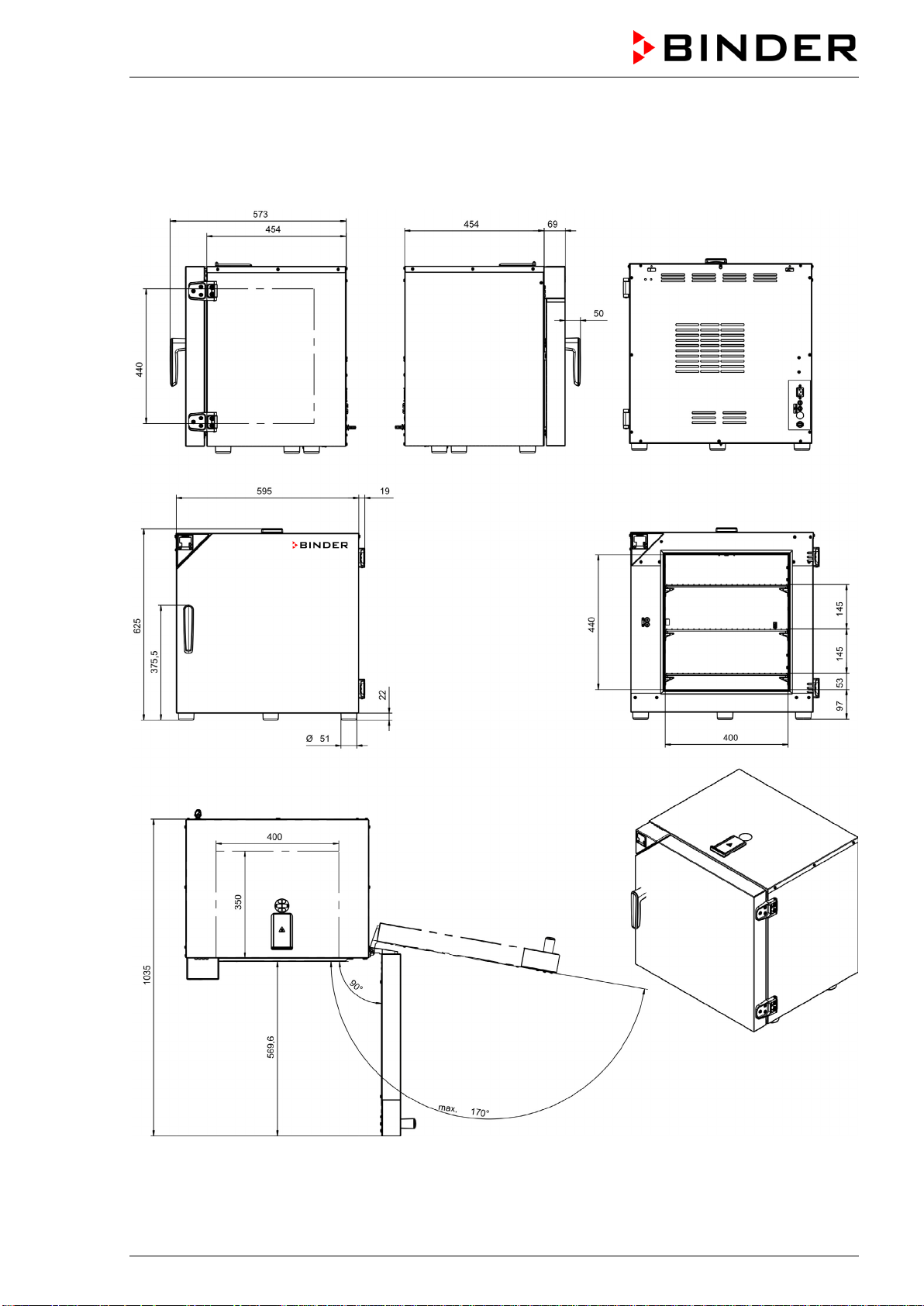
BD-S / BD-S-UL, ED-S / ED-S-UL, FD-S / FD-S-UL (E1) 10/2020 page 36/59
16.7 Dimensioned drawings
16.7.1 BD-S / BD-S-UL 56
[mm]
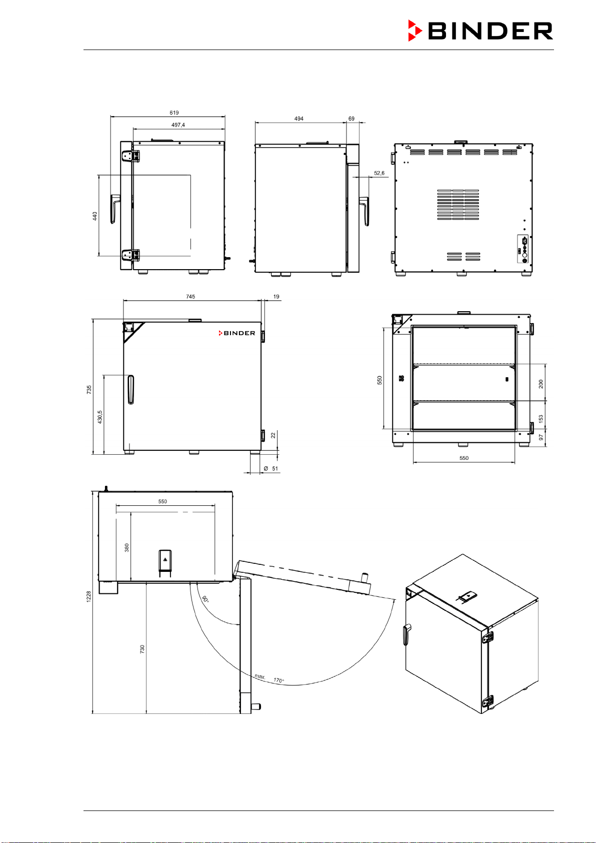
BD-S / BD-S-UL, ED-S / ED-S-UL, FD-S / FD-S-UL (E1) 10/2020 page 37/59
16.7.2 BD-S / BD-S-UL 115
[mm]
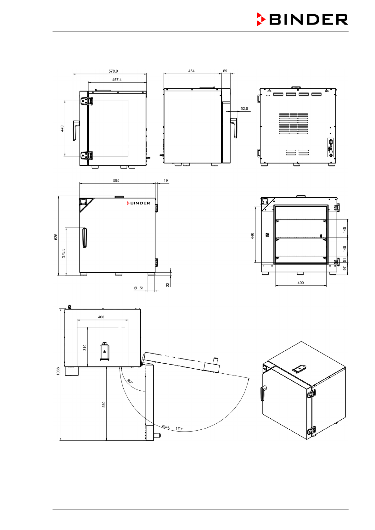
BD-S / BD-S-UL, ED-S / ED-S-UL, FD-S / FD-S-UL (E1) 10/2020 page 38/59
16.7.3 ED-S / ED-S-UL 56
[mm]

BD-S / BD-S-UL, ED-S / ED-S-UL, FD-S / FD-S-UL (E1) 10/2020 page 39/59
16.7.4 ED-S / ED-S-UL 115
[mm]
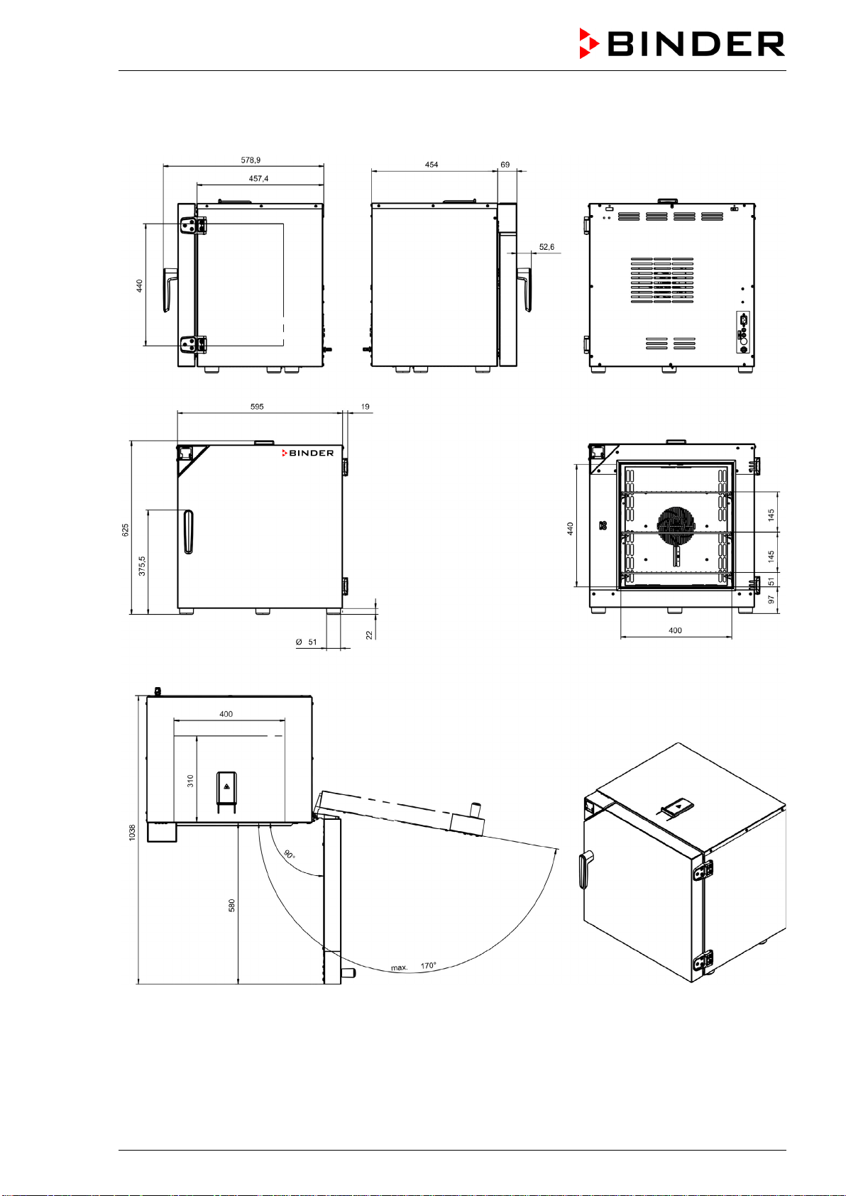
BD-S / BD-S-UL, ED-S / ED-S-UL, FD-S / FD-S-UL (E1) 10/2020 page 40/59
16.7.5 FD-S / FD-S-UL 56
[mm]
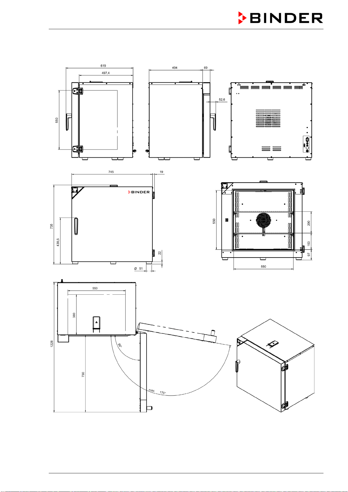
BD-S / BD-S-UL, ED-S / ED-S-UL, FD-S / FD-S-UL (E1) 10/2020 page 41/59
16.7.6 FD-S / FD-S-UL 115
[mm]
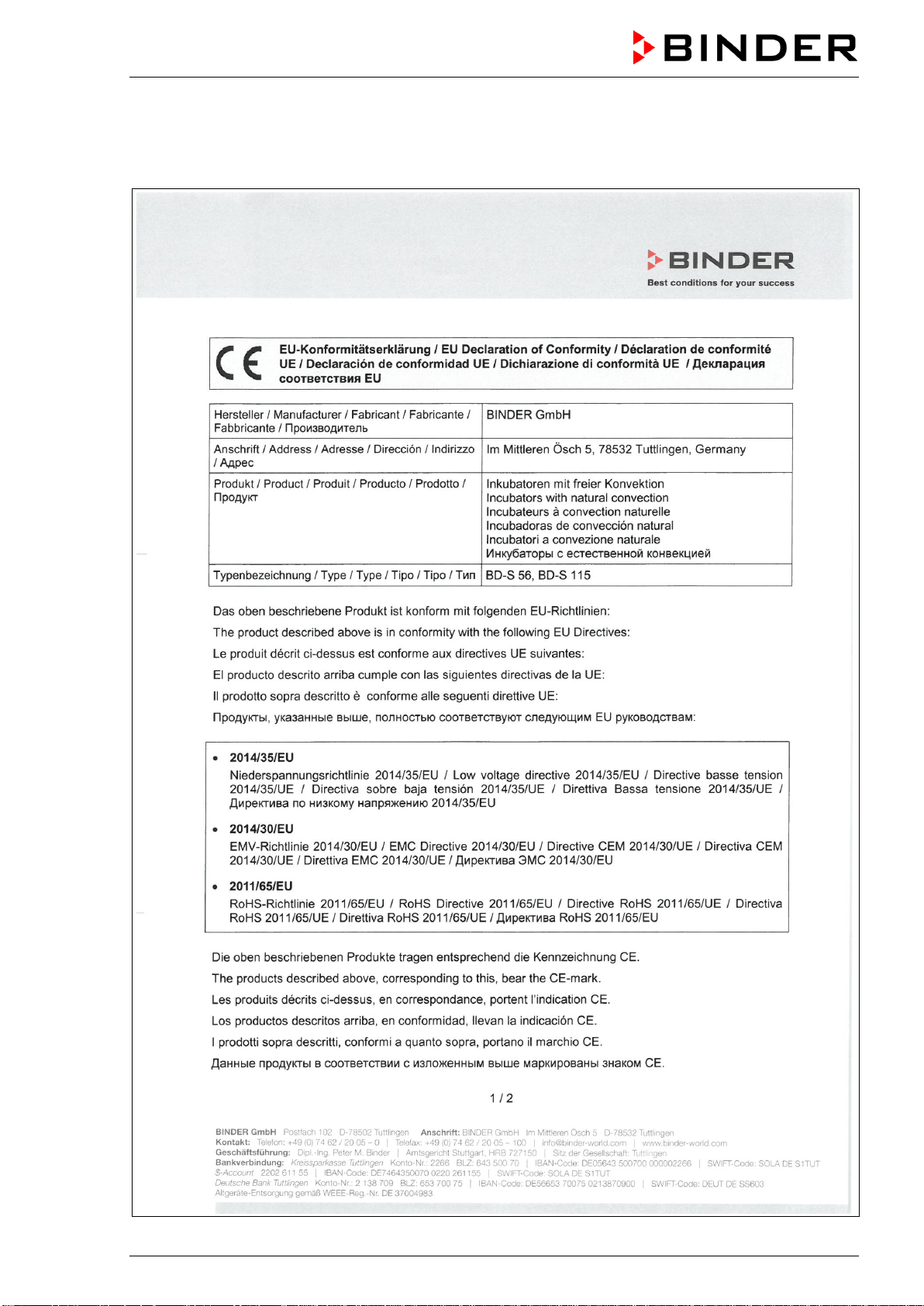
BD-S / BD-S-UL, ED-S / ED-S-UL, FD-S / FD-S-UL (E1) 10/2020 page 42/59
17. Certificates and declarations of conformity
17.1 EU Declaration of Conformity for BD-S
BD-S / BD-S-UL, ED-S / ED-S-UL, FD-S / FD-S-UL (E1) 10/2020 page 43/59
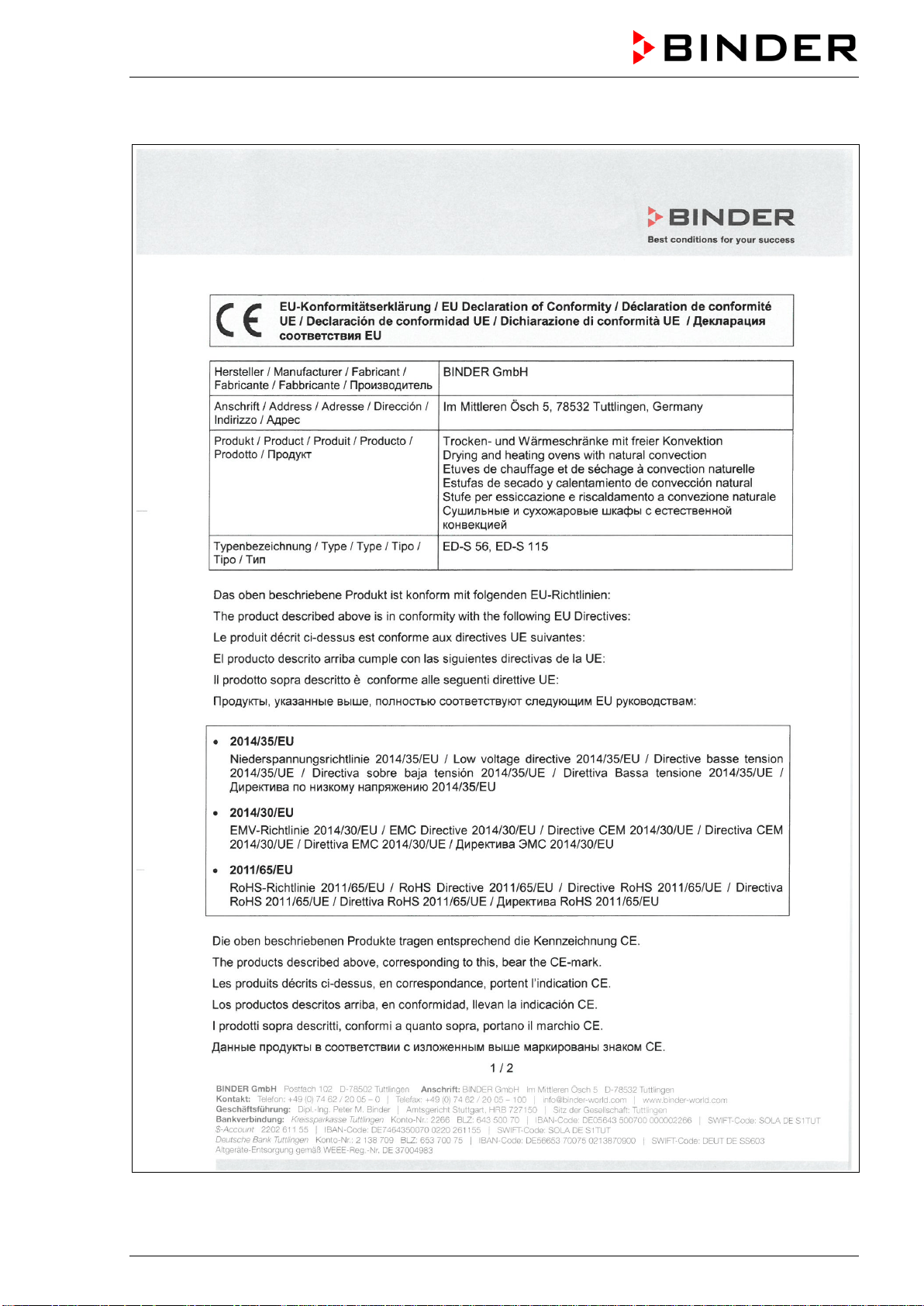
BD-S / BD-S-UL, ED-S / ED-S-UL, FD-S / FD-S-UL (E1) 10/2020 page 44/59
17.2 EU Declaration of Conformity for ED-S
BD-S / BD-S-UL, ED-S / ED-S-UL, FD-S / FD-S-UL (E1) 10/2020 page 45/59
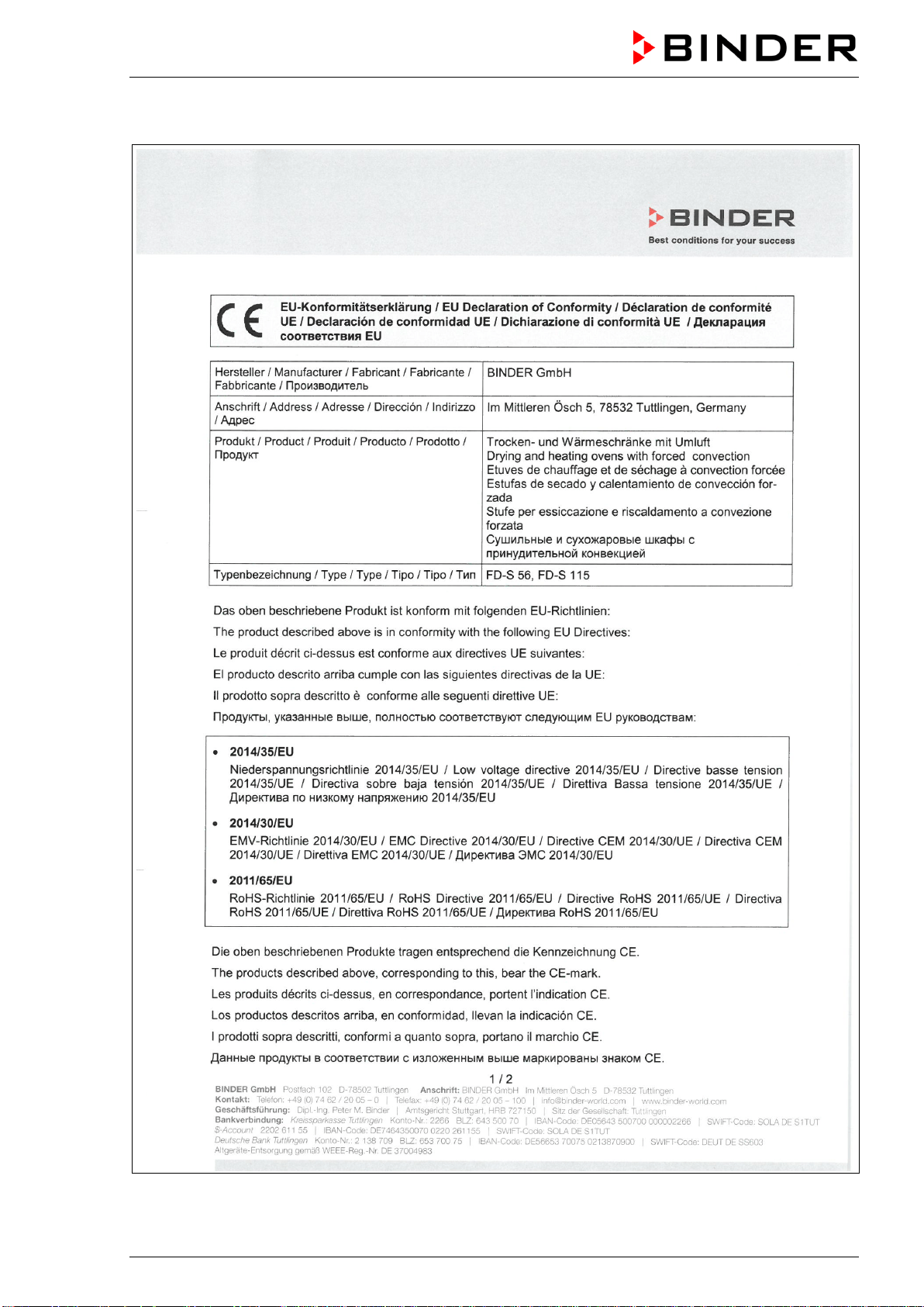
BD-S / BD-S-UL, ED-S / ED-S-UL, FD-S / FD-S-UL (E1) 10/2020 page 46/59
17.3 EU Declaration of Conformity for FD-S
BD-S / BD-S-UL, ED-S / ED-S-UL, FD-S / FD-S-UL (E1) 10/2020 page 47/59
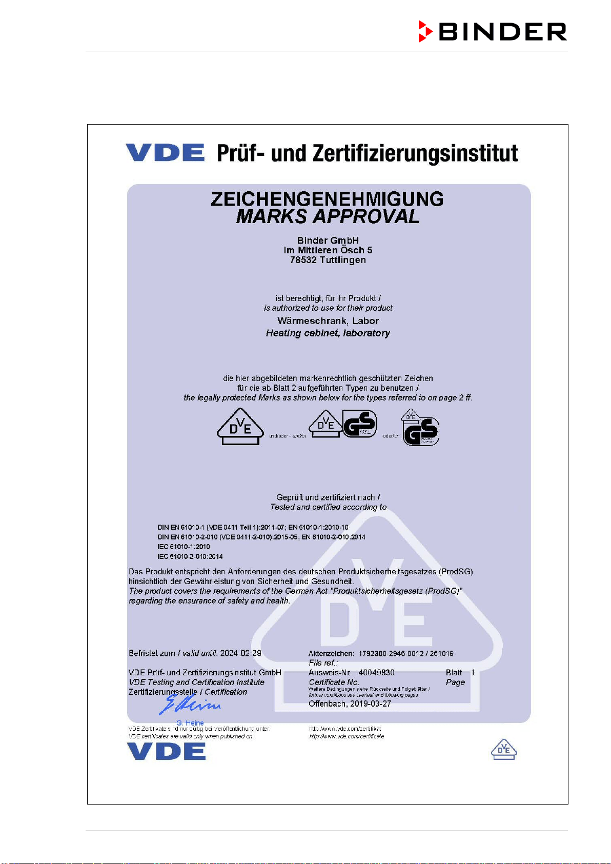
BD-S / BD-S-UL, ED-S / ED-S-UL, FD-S / FD-S-UL (E1) 10/2020 page 48/59
17.4 Certificate for the GS mark of conformity of the “VDE Prüf- und Zertifizier-
ungsinstitut” (Testing and Certification Institute of the Association for Elec-
trical, Electronic and Information Technologies)
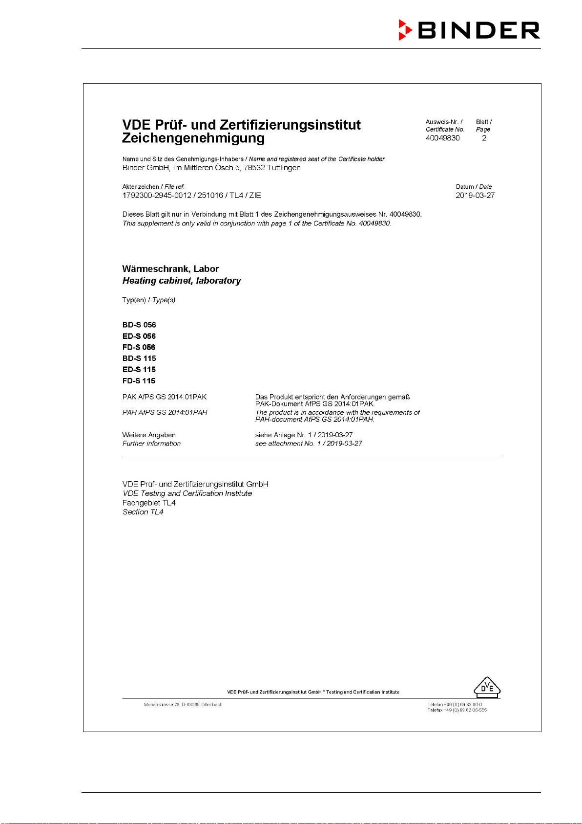
BD-S / BD-S-UL, ED-S / ED-S-UL, FD-S / FD-S-UL (E1) 10/2020 page 49/59
BD-S / BD-S-UL, ED-S / ED-S-UL, FD-S / FD-S-UL (E1) 10/2020 page 50/59
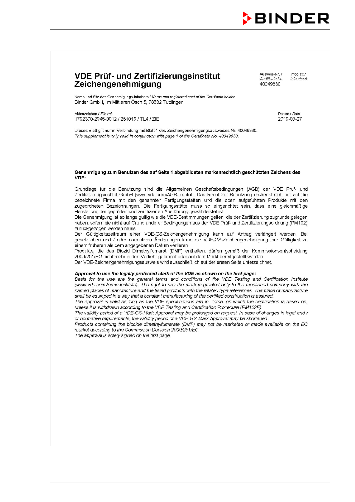
BD-S / BD-S-UL, ED-S / ED-S-UL, FD-S / FD-S-UL (E1) 10/2020 page 51/59
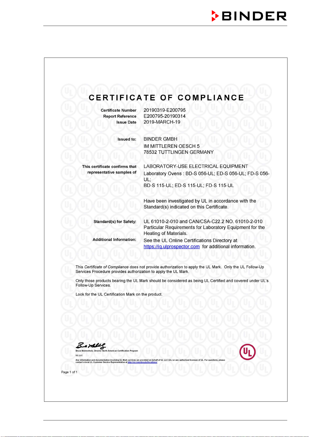
BD-S / BD-S-UL, ED-S / ED-S-UL, FD-S / FD-S-UL (E1) 10/2020 page 52/59
17.5 Certificate of UL Compliance from Underwriters Laboratories Inc.
®
Valid for UL chambers only
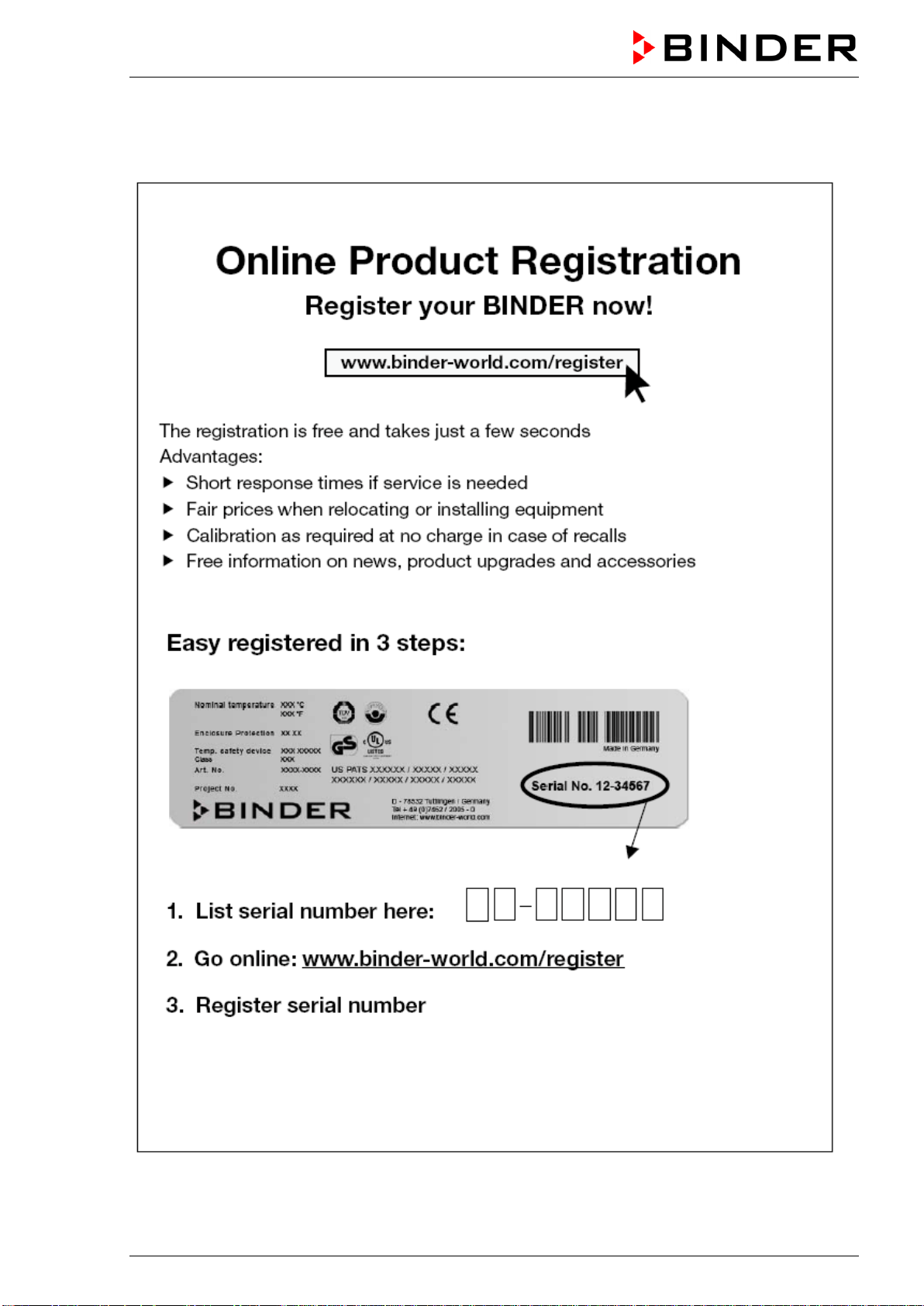
BD-S / BD-S-UL, ED-S / ED-S-UL, FD-S / FD-S-UL (E1) 10/2020 page 53/59
18. Product registration

BD-S / BD-S-UL, ED-S / ED-S-UL, FD-S / FD-S-UL (E1) 10/2020 page 54/59
19. Contamination clearance certificate
19.1 For chambers located outside the USA and Canada
Declaration with regard to safety and health
Erklärung zur Sicherheit und gesundheitlichen Unbedenklichkeit
The German Ordinance on Hazardous Substances (GefStofV), and the regulations regarding safety at
the workplace, require that this form be filled out for all products that are returned to us, so that the safety
and health of our employees can be warranted.
Die Sicherheit und Gesundheit unserer Mitarbeiter, die Gefahrstoffverordnung GefStofV und die Vorschriften zur
Sicherheit am Arbeitsplatz machen es erforderlich, dass dieses Formblatt für alle Produkte, die an uns zurückge-
schickt wird.
In the absence of a completely filled out form, a repair is not possible.
Ohne Vorliegen des vollständig ausgefüllten Formblattes ist eine Reparatur nicht möglich.
• A completely filled out form should be transmitted by Fax (+49 (0) 7462 2005 93555) or by letter in
advance to us, so that this information is available before the equipment/component part arrives. A
second copy of this form should accompany the equipment/component part. Eventually the carrier
should be informed.
Eine vollständig ausgefüllte Kopie dieses Formblattes soll per Telefax (Nr. +49 (0) 7462 2005 93555) oder Brief
vorab an uns gesandt werden, so dass die Information vorliegt, bevor das Gerät/Bauteil eintrifft. Eine weitere Ko-
pie soll dem Gerät/Bauteil beigefügt sein. Ggf. ist auch die Spedition zu informieren.
•
Incomplete information or non-conformity with this procedure will inevitably lead to substantial delays
in processing. We hope you will have understanding for this measure, which lies outside of our area of
influence, and that you will help us to speed up this procedure.
Unvollständige Angaben oder Nichteinhalten dieses Ablaufs führen zwangsläufig zu beträchtlichen Verzögerun-
gen in der Abwicklung. Bitte haben Sie Verständnis für Maßnahmen, die außerhalb unserer Einflussmöglichkeiten
liegen und helfen Sie mit, den Ablauf beschleunigen.
•
Please fill out this form completely.
Bitte unbedingt vollständig ausfüllen!
1. Chamber/ component part / type: / Gerät / Bauteil / Typ:
2. Serial No./ Serien-Nr.:
3. Details about utilized substances / biological substances / Einzelheiten über die eingesetzten
Substanzen/biologische Materialien:
3.1 Designations / Bezeichnungen:
a) ____________________________________________________________________________
b) ____________________________________________________________________________
c) ____________________________________________________________________________
3.2 Safety measures required for handling these substances / Vorsichtsmaßnahmen beim Um-
gang mit diesen Stoffen:
a) ____________________________________________________________________________
b) ____________________________________________________________________________
c) ____________________________________________________________________________

BD-S / BD-S-UL, ED-S / ED-S-UL, FD-S / FD-S-UL (E1) 10/2020 page 55/59
3.3 Measures to be taken in case of skin contact or release into the atmosphere / Maßnahmen
bei Personenkontakt oder Freisetzung:
a) ____________________________________________________________________________
b) ____________________________________________________________________________
c) ____________________________________________________________________________
d) ____________________________________________________________________________
3.4 Other important information that must be taken into account / Weitere zu beachtende und
wichtige Informationen:
a) ____________________________________________________________________________
b) ____________________________________________________________________________
c) ____________________________________________________________________________
4. Declaration on the risk of these substances (please checkmark the applicable items) /
Erklärung zur Gefährlichkeit der Stoffe (bitte Zutreffendes ankreuzen) :
4.1 For non toxic, non radioactive, biologically harmless materials / für nicht giftige, nicht radio-
aktive, biologisch ungefährliche Stoffe:
We herewith guarantee that the above-mentioned chamber / component part… /
Wir versichern,
dass o.g. Gerät/Bauteil...
Has not been exposed to or contains any toxic or otherwise hazardous substances /
weder giftige noch
sonstige gefährliche Stoffe enthält oder solche anhaften.
That eventually generated reaction products are non-toxic and also do not represent a hazard / auch
evtl. entstandene Reaktionsprodukte weder giftig sind noch sonst eine Gefährdung darstellen.
Eventual residues of hazardous substances have been removed /
evtl. Rückstände von Gefahrstoffen
entfernt wurden.
4.2 For toxic, radioactive, biologically harmful or hazardous substances, or any other ha-
zardous materials /
für giftige, radioaktive, biologisch bedenkliche bzw. gefährliche Stoffe oder
anderweitig gefährliche Stoffe.
We herewith guarantee that … / Wir versichern, dass …
The hazardous substances, which have come into contact with the above-mentioned equip-
ment/component part, have been completely listed under item 3.1 and that all information in this re-
gard is complete /
die gefährlichen Stoffe, die mit dem o.g. Gerät/Baute
il in Kontakt kamen, in 3.1 aufgelistet
sind und alle Angaben vollständig sind.
That the chamber /component part has not been in contact with radioactivity /
das Gerät/Bauteil nicht mit
Radioaktivität in Berührung kam
5. Kind of transport / transporter / Transportweg/Spediteur:
Transport by (means and name of transport company, etc.) Versendung durch (Name Spediteur o.ä.)
___________________________________________________________________________________
Date of dispatch to BINDER GmbH / Tag der Absendung an BINDER GmbH:
___________________________________________________________________________________
BD-S / BD-S-UL, ED-S / ED-S-UL, FD-S / FD-S-UL (E1) 10/2020 page 56/59
We herewith declare that the following measures have been taken / Wir erklären, dass folgende
Maßnahmen getroffen wurden:
Hazardous substances were removed from the chamber
/ component part, so that no hazard exists for
corresponding persons in the handling or repair of these items / das Gerät/Bauteil wurde von Gefahrstof-
fen befreit, so dass bei Handhabung/Reparaturen für die betreffenden Person keinerlei Gefährdung besteht
The chamber was securely packaged and properly identified / das Gerät wurde sicher verpackt und voll-
ständig gekennzeichnet.
Information about the hazardousness of the shipment (if required) has been provided to the transpor-
ter /
der Spediteur wurde (falls vorgeschrieben) über die Gefährlichkeit der Sendung informiert.
We herewith commit ourselves and guarantee that we will indemnify BINDER GmbH for all damages that
are a consequence of incomple
te or incorrect information provided by us, and that we will exempt
BINDER GmbH from eventual damage claims by third parties./
Wir versichern, dass wir gegenüber BINDER
für jeden Schaden, der durch unvollständige und unrichtige Angaben entsteht, haften un
d BINDER gegen eventuell
entstehende Schadenansprüche Dritter freistellen.
We are aware that, in accordance with Article 823 of the German Civil Code (BGB), we are directly liable
with regard to third parties, in this instance especially the employees of
BINDER GmbH, who have been
entrusted with the handling / repair of the chamber / component. /
Es ist uns bekannt, dass wir gegenüber
Dritten –
hier insbesondere mit der Handhabung/Reparatur des Geräts/des Bauteils betraute Mitarbeiter der Firma
BINDER - gemäß §823 BGB direkt haften
Name: _______________________________________________________________________
Position: _______________________________________________________________________
Date /
Datum: _______________________________________________________________________
Signature / Unterschrift: ______________________________________________________________
Company stamp /
Firmenstempel:
Equipment that is returned to the factory for repair must be accompanied by a completely filled
out contamination clearance certificate. For service and maintenance works on site, such a
contamination clearance certificate must be submitted to the service technician before the
start of the works. No repair or maintenance of the equipment is possible, without a properly
filled out contamination clearance certificate.
BD-S / BD-S-UL, ED-S / ED-S-UL, FD-S / FD-S-UL (E1) 10/2020 page 57/59
19.2 For chambers located in the USA and Canada
Product Return Authorization Request
Please complete this form and the Customer Decontamination Declaration (next 2 pages) and attach the
required pictures. E-mail to: IDL_SalesOrderProcessing_USA@binder-world.com
After we have received and reviewed the complete information we will decide on the issue of a RMA
number. Please be aware that size specifications, voltage specifications as well as performance specifi-
cations are available on the internet at www.binder-world.us
at any time.
Take notice of shipping laws and regulations.
Please fill:
Reason for return request Duplicate order
Duplicate shipment
Demo Page one completed by sales
Power Plug / Voltage 115V / 230 V / 208 V / 240V
Size does not fit space
Transport Damage Shock watch tripped? (pictures)
Other (specify below)
_____________________
Is there a replacement PO? Yes No
If yes -> PO #
If yes -> Date PO placed
Purchase order number
BINDER model number
BINDER serial number
Date chamber was received
Was the chamber unboxed? Yes No
Was the chamber plugged
in?
Yes No
Was the chamber in opera-
tion?
Yes No
Pictures of chamber at-
tached?
Pictures of Packaging at-
tached?
Yes No
Yes No
Pictures have to be attached!
Customer Contact Information Distributor Contact Information
Name
Company
Address
Phone
E-mail
BD-S / BD-S-UL, ED-S / ED-S-UL, FD-S / FD-S-UL (E1) 10/2020 page 58/59
Customer (End User) Decontamination Declaration
Health and Hazard Safety declaration
To protect the health of our employees and the safety at the workplace, we require that this form is com-
pleted by the user for all products and parts that are returned to us. (Distributors or Service Organizations
cannot sign this form)
NO RMA number will be issued without a completed form. Products or parts returned to our
NY warehouse without a RMA number will be refused at the dock.
A second copy of the completed form must be attached to the outside of the shipping box.
1. Chamber/ component part / type
:
2. Serial No.
3. List any exposure to hazardous liquids, gasses or substances and radioactive material
3.1 List with MSDS sheets attached where available or needed
(if there is not enough space available below, please attach a page):
a) ____________________________________________________________________________
b) ____________________________________________________________________________
c) ____________________________________________________________________________
3.2 Safety measures required for handling the list under 3.1
a) ____________________________________________________________________________
b) ____________________________________________________________________________
c) ____________________________________________________________________________
3.3 Measures to be taken in case of skin contact or release into the atmosphere
:
a) ____________________________________________________________________________
b) ____________________________________________________________________________
c) ____________________________________________________________________________
d) ____________________________________________________________________________
3.4 Other important information that must be considered
:
a) ____________________________________________________________________________
b) ____________________________________________________________________________
c) ____________________________________________________________________________
BD-S / BD-S-UL, ED-S / ED-S-UL, FD-S / FD-S-UL (E1) 10/2020 page 59/59
4. Declaration of Decontamination
For toxic, radioactive, biologically and chemically harmful or hazardous substances, or any other
hazardous materials.
We hereby guarantee that
4.1 Any hazardous substances, which have come into contact with the above-mentioned equipment /
component part, have been completely listed under item 3.1 and that all information in this regard is
complete
.
4.2 That the chamber /component part has not been in contact with radioactivity
4.3 Any Hazardous substances were removed from the chamber / component part, so that no hazard
exists for a persons in the shipping, handling or repair of these returned chamber
4.4 The chamber was securely packaged in the original undamaged packaging and properly identified
on the outside of the packaging material with the chamber designation, the RMA number and a
copy of this declaration.
4.5 Shipping laws and regulations have not been violated.
I hereby commit and guarantee that we will indemnify BINDER Inc. for all damages that are a
consequence of incomplete or incorrect information provided by us, and that we will indemnify
and hold harmless BINDER Inc. from eventual damage claims by third parties.
Name: _______________________________________________________________________
Position: _______________________________________________________________________
Company: _______________________________________________________________________
Address: _______________________________________________________________________
Phone #: _______________________________________________________________________
Email: _______________________________________________________________________
Date: _______________________________________________________________________
Signature: _______________________________________________________________________
Equipment returned to the NY warehouse for repair must be accompanied by a completed
customer decontamination declaration. For service and maintenance works on site, such a
customer decontamination declaration must be submitted to the service technician before the
start of work. No repair or maintenance of the equipment is possible without a completed form.