Loading ...
Loading ...
Loading ...
9
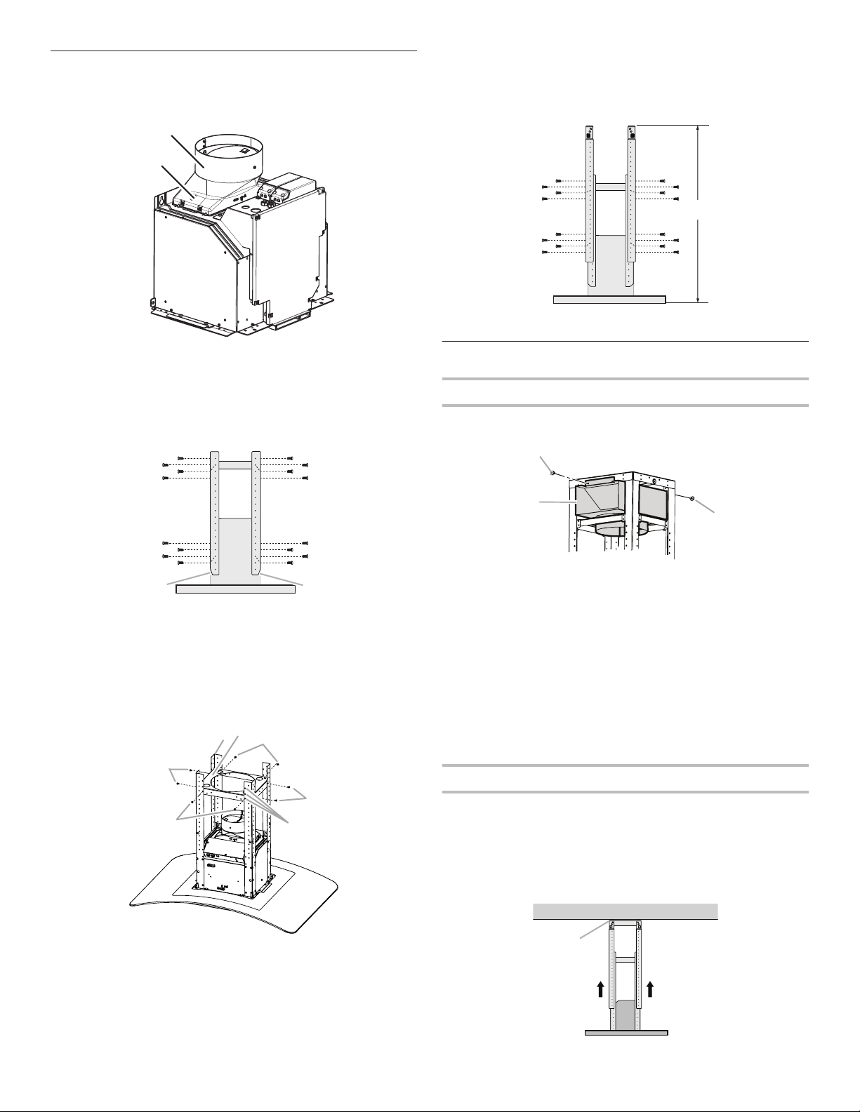
Assemble Range Hood
1. Install transition on top of hood (if removed for shipping)
with 2 - 3.5 x 9.5 mm Phillips drive sheet metal screws.
2. Position the 4 vertical supports (A) with the notches
at the bottom and attach to the range hood using
16 - 4.2 x 8 mm T20
®
screws. Use a T20
®
Torx
®
drive
(or T20
®
adapter provided) to tighten all assembly screws.
3. Position the lower horizontal support (B) as shown (flanges
pointed down). Attach to the lower vertical supports using
8 - 4.2 x 8 mm T20
®
screws. The lower horizontal support
can be positioned at any of the three mounting hole
locations in the lower vertical supports.
4. Attach a second set of vertical supports (A) and set
the vertical height (B). See “Installation Dimensions”
in the “Location Requirements” section to help
determine the desired dimension for vertical height “B.”
Secure with 16 - 4.2 x 8 mm T20
®
screws.
Install Range Hood
Non-Vented (recirculating) Installation
1. Attach the air deflector to the upper horizontal support
using 2 - 4.2 x 8 mm T20
®
mounting screws.
2. Measure the length of 6" (15.2 cm) duct needed
to connect the transition to the deflector.
NOTE: Vent should fit up inside the deflector
1" (2.5 cm) minimum.
3. Install vent between the transition and the deflector.
NOTE: To make vent installation easier, temporarily remove
the deflector from the chimney support bracket and replace
after vent section is in place.
4. Seal all connections with vent clamps. Continue
with “Range Hood Installation” in this section.
Range Hood Installation
1. Using 2 or more people, lift the range hood assembly
and attach it by snapping the vertical supports to the
spring clips in the upper horizontal support bracket
that is mounted to the ceiling.
NOTE: The range hood assembly must be held in place
while you are installing the screws in the next step.
2. Install 16 - 4.2 x 8 mm T20
®
screws and tighten to secure.
A
B
A. Vent transition
B. 3.5 x 9.5 mm screw
B
A
A
C
C
A. Vertical supports
B. Horizontal support
C. Notched end
A
B
C
C
C
C
D
A. Vertical supports (4)
B. Horizontal support
C. Screws 4.2 x 8 mm T20
®
(8)
D. Mounting hole locations for horizontal support
B
A
A
A. Vertical supports
B. Vertical height
B
B
A
A. Deflector
B. 2 - 4.2 x 8 mm T20
®
mounting screws
A
A. Mounting screws
Loading ...
Loading ...
Loading ...