1. No power to pressure switch due to blown fuses, open switches or loose connections.
2. Pump pressure switch not closed.
b. Pump fails to deliver water:
1. Pump not completely primed.
2. Suction lift is too great.
3. Foot valve is either not submerged, buried in mud or plugged.
c. Pump loses prime:
1. Air leaks in suction line.
2. Well drawn down too far.
3. Faulty foot valve.
d. Pump delivers water but not at rated capacity:
1. Leaks in suction or discharge line.
2. Foot valve, suction line, impeller or nozzle are partially plugged.
3. Suction lift is greater than recommended.
4. Improper impeller rotation or low speed.
5. Venturi or diffuser is plugged.
6. Motor is wired for improper voltage.
7. Low line voltage at motor.
8. Motor does not come off starting windings (improper motor switch adjustment).
e. Pump starts and stops too often:
1. Faulty air volume control.
2. Air leaks in tank above the water level.
3. Incorrect setting on pressure switch.
4. Tank is water logged or too small for application.
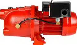
RJC – SELF-PRIMING CONVERTIBLE JET PUMPS
a. Motor will not start:
1. No power to pressure switch due to blown fuses, open switches or loose connections.
2. Pump pressure switch not closed.
b. Pump fails to deliver water:
1. Pump not completely primed.
2. Suction lift is too great.
3. Foot valve is either not submerged, buried in mud or plugged.
4. Restrictor valve is fully closed.
c. Pump loses prime:
1. Air leaks in suction line.
2. Well drawn down too far and requires a tail-pipe.
3. Faulty foot valve.
d. Pump delivers water but not at rated capacity:
1. Leaks in suction or discharge line.
2. Foot valve, suction line, impeller or nozzle are partially plugged.
3. Suction lift is greater than recommended.
4. Improper setting of control valve on deep well units.
5. Improper impeller rotation or low speed.
6. Venturi or diffuser is plugged.
7. Motor is wired for improper voltage.
8. Low line voltage at motor.
e. Pump starts and stops too often:
1. Air leaks in tank above the water level.
2. Incorrect setting on pressure switch.
3. Tank is water logged or incorrectly charged.
4. Foot valve leaks or is stuck open.
Sand Point Applications
Trouble
Possible Solution
Pump noisy - output requirement exceeds available capacity.
Install/adjust valve on discharge to reduce output.
Pump runs hot/won't shut off. Can not build pressure due to lack of water at source.
Install low pressure cut-off switch to shut down pump prior to critical failure.
Changes in requirement not being met by current system (added bathroom, irrigations, etc.)
Increase pressure cut-off switch to offset peak period demand from insufficient source.
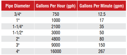
Recommended Maximum Flow Rates
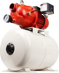
PRE-CHARGED PRESSURE TANKS
Can I install my Red Lion diaphragm pressure tank on its side?
Side installations are acceptable up to the RL44 size. We do not recommend horizontal installations for any tanks larger than the RL44.
What is the warranty on Red Lion tanks?
All Red Lion tanks carry a 5 year limited warranty from the date of manufacture on the original tank.
My tank was just installed and the water has a funny taste – what should I do?
Flush the new tank by allowing water to flow through three or four pump cycles. If the taste continues, you should probably have the source water tested.
Can I use chlorinated water with my Red Lion tank?
Of course. Red Lion tanks are designed with the knowledge that chlorine is often used to periodically treat a well.
What is drawdown?
Drawdown refers to the amount of water that evacuates the tank before the pressure switch will activate the pump. Drawdown is affected by the pump, the size of the tank, and the pressure settings that govern your water system.
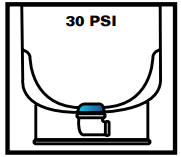
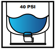
Tank system operation
1. Pump comes on and begins to fill tank.
2. Pump continues to run, compressing air charge in tank.
3. Pump shuts off. Drawdown water is available on demand.
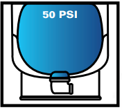
What is pre-charge pressure?
Pre-charge pressure refers to the amount of air in psi that is pumped into a tank prior to installation – usually at the factory. Most tanks are provided with a 28 psi pre-charge (38 psi in the RL81 to RL119 sizes). The pre-charge is the "spring" that helps to create water pressure. As the diaphragm fills with water, it compresses the pre-charge. In a 30/50 system, the pump will continue to propel water into the tank until the pressure in the tank reaches 50 psi.
How much pressure (pre-charge) should be in my tank?
Your tanks should be pressurized to 2 psi less than the cut-in pressure setting (for example, if your pressure settings are 30/50, then your cut-in pressure setting is 30 psi and your tank should have a 28 psi pre-charge).
How do I check or change my pre-charge?
You must completely drain the tank to check pre-charge. To do this, shut the power off to the pump and open (turn-on) a faucet in the house. This will drain the tank and not allow it to refill. On the top of the tank you will find an air valve (similar to the air valve on your tires) – use a tire pressure gauge to check the air pressure.
4" SUBMERSIBLE WELL PUMPS
Trouble
Possible Cause
Corrective Action
Motor will not start but does not blow fuses.
WARNING! Hazardous voltage. Can shock, burn or cause death. Qualified electricians should work on electrical service.
No voltage to motor.
With a voltmeter check: 1) fuse box to make sure full voltage is available; 2) pressure switch terminals to make sure pressure switch is passing voltage correctly; and 3) terminal strips in pump control box or disconnect switch box to make sure voltage is available there. On 1-½ through 3 hp: push red overload reset button(s) on the bottom of the control center.
Cable splices or motor windings may be grounded, shorted or open-circuited.
Consult certified electrician or service technician.
Do not attempt to disassemble pump or motor.
Faulty pressure switch.
Check pressure switch; replace if necessary.
3-wire only; open circuit in pump control box; faulty connections; faulty wires.
Examine all connections and wires; examine terminal strips in the control center (3-wire only); repair if necessary
3-wire only; cable leads improperly connected in the control center.
Check wiring diagram on control center panel and color coding of drop cable.
Pressure switch fails to shut off pump.
Voltage is too low; motor will run slowly, causing low discharge pressure (head) and high operating current draw.
Have a certified electrician verify voltage at the electrical disconnect box (2-wire) or control center (3-wire) while the pump is operating. If the voltage is low, the power company may need to raise it or installation may require larger wire. Discuss this with the power company or a certified electrician. Check voltage with a recording meter if trouble reoccurs.
Faulty pressure switch.
Replace switch.
Drop pipe is leaking.
Raise one length at a time until the leak is found. When water stands in the pipe, there is no leak below this point.
Water level in the well may become too low when pump is running.
Lower the pump further into the well, but make sure it is at least five feet from the bottom of the well. Install a control valve in the discharge pipe between the pump and pressure tank. Use the control valve to restrict the flow until the discharge rate does not exceed well recovery rate.
WARNING! To prevent the possibility of dangerously high pressure, install a relief valve in the discharge pipe between the pump and flow restriction valve. The relief valve must be capable of passing full pump flow at 75 psi.
Fuses blow or overload protector trips when motor is running.
Low or high voltage.
While the motor is running, voltage should not exceed plus 5% or minus 5% of rated voltage shown on motor nameplate. Plus 3% or minus 3% in Canada. Call your power company to adjust line voltage if it is not within these limits.
Wire size is too small. Improperly connected in the pump control box.
See cable selection guide in the technical data section and make sure the wire sizes match specifications in table.
Cable splices or motor windings may be grounded, shorted or open-circuited.
Consult certified electrician or a service technician to determine if this is the cause of the problem or not. Do not attempt to disassemble the pump or motor.
3-wire only; high ambient (atmospheric) temperature.
Make sure the pump control box is installed out of direct sunlight.
3-wire only; pump control box wrong horsepower or voltage for installation.
Compare horsepower and voltage rating of motor (from motor nameplate) with those of the pump control box (from pump control box nameplate). These numbers must match.
Air or milky water discharges from your faucets.
Well water may be gaseous.
If your well is naturally gaseous and your system has a standard tank, remove the bleeder orifices and plug the tees. If the condition is serious, check with a certified well professional.
Your pump delivers little or no water.
Water level in a low producing well drops too low while pump is operating, causing it to air lock (resulting in loss of prime and possibly serious damage to the pump).
Lower the pump further into the well, but make sure it is at least five feet from the bottom of the well. Install a control valve in the discharge pipe between the pump and pressure tank. Use the control valve to restrict the flow until the discharge rate does not exceed well recovery rate.
WARNING! To prevent the possibility of dangerously high pressure, install a relief valve in the discharge pipe between the pump and flow restriction valve. Relief valve must be capable of passing full pump flow at 75 psi.
Intake screen is partially plugged.
Lime or other matter in the water may build up on screen. Pull pump and clean screen.
Check valve(s) may be stuck.
Make sure that the built-in check valve in the pump and any check valves in the discharge line are free to open properly.
Voltage is too low; the motor runs slowly, causing low discharge pressure (head) and high operating current draw.
Have a certified electrician verify voltage at the electrical disconnect box (2-wire) or control center (3-wire) while the pump is operating. If the voltage is low, the power company may need to raise it or installation may require larger wire. Discuss this with the power company or a certified electrician. Check voltage with a recording meter if trouble reoccurs.
Pump starts too frequently.
Leak in the pressure tank or plumbing.
Check all connections with soap suds for air leaks. Fix any leaks you find. Check the plumbing for water leaks. Fix any leaks you find.
Pressure switch is defective or out of adjustment.
If necessary, replace switch.
Check valve is leaking.
Inspect valves and replace if necessary
Tank is waterlogged.
Captive air tanks: Check the tank for leaks; correct if possible. Pre-charge tanks to 18 psi with a 20-40 psi switch, 28 psi for a 30-50 switch, 38 psi for a 40-60 psi switch, etc. Standard tanks: Check the tank for leaks; correct if possible. Check bleeder orifices and clean bleeders; replace if necessary.
Drop pipe leaking.
Raise one length of pipe at a time until the leak is found. When water stands in the pipe there is no leak below this point.
Pressure switch is too far from the tank.
Move the pressure switch to within one foot of the tank.
Fuses blow or overload protector trips when motor starts.
Low or high voltage.
While the motor is running, voltage should not exceed plus 5% or minus 5% of rated voltage shown on motor nameplate. Plus 3% or minus 3% in Canada. Call your power company to adjust line voltage if it is not within these limits.
Wire size is too small. Improperly connected in the pump control box.
See cable selection guide in the technical data section and make sure the wire sizes match specifications in table.
Cable splices or motor windings may be grounded, shorted or open-circuited.
Consult certified electrician or a service technician to determine if this is the cause of the problem or not. Do not attempt to disassemble the pump or motor.
3-wire only; cable leads may be improperly connected in pump control box, pressure switch or fused disconnect switch.
Check wiring diagram on pump control box and color coding of drop cable.
3-wire only; there may be a broken wire in the pump control box.
Employ a certified electrician to examine all connections and wiring in control panel. If necessary, repair them.
3-wire only; starting or running capacitor in control box may be defective or vented (blown out).
Inspect capacitors. Employ a certified electrician to check capacitors and replace them if necessary.
WARNING! Hazardous voltage; can shock, burn or cause death. Capacitors may still carry voltage charges even after being disconnected from wiring. Have them checked by a certified electrician.
SUBMERSIBLE UTILITY & SUMP PUMPS
Trouble
Possible Cause
Corrective Action
Motor does not run.
Blown fuse.
Replace fuse.
Tripped circuit
Reset.
Disconnected plug.
Reinstall pump.
Corroded plug.
Clean prongs.
Tripped overload.
Allow pump to cool, investigate cause (i.e. jammed impeller).
Defective switch.
Replace switch.
Defective motor.
Replace pump.
Float obstructed.
Check for freedom of movement. Ensure switch isn't touching wall of basin or pit.
Impeller jammed.
Plugged check valve.
Remove bottom plate and clean.
Plugged check valve.
Remove valve, clean or replace.
Partially blocked inlet
Clean inlet.
Line leak.
Repair line.
Worn impeller.
Replace pump/repair
Defective motor.
Replace pump.
Plugged inlet.
Plugged inlet.
Clean inlet.
Defective switch.
Replace switch.
Float obstruction.
Adjust position of pump.
Clean inlet.
Remove valve, clean or replace.
CAUTION A plugged pump inlet can be mistaken for a faulty switch. If the pump runs continuously or for extended periods of time between turn offs, first check for a partially plugged inlet.
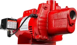
RL-S - CAST IRON SURFACE EFFLUENT PUMP
& RL-50 - SELF-PRIMING MULTI-PURPOSE TRANSFER PUMP
a. Pump fails to prime or primes slowly:
1. Leaks in suction line.
2. Loose gasket connection due to shrinkage of the gasket.
3. Collapsed or clogged suction line.
4. Not enough water in the casing for priming.
5. Suction lift is too great.
b. Reduced pressure or capacity:
1. Partially collapsed or clogged suction line.
2. Clogged impeller.
3. Leaks in the suction line.
4. Strainer or end suction hose is not properly submerged.
5. Suction line is improperly installed, resulting in air pockets in the suction line.
6. Suction lift is too great (the greater the suction lift, the lower the capacity and pressure).
7. Worn parts, such as the impeller or the pump casing.
RJSE - CAST IRON SPRINKLER UTILITY PUMP
a. Motor will not start:
1. No power to pressure switch due to blown fuses, open switches or loose connections.
2. Pump pressure switch not closed.
b. Pump fails to deliver water:
1. Pump not completely primed.
2. Suction lift is too great.
3. Foot valve is either not submerged, buried in mud or plugged.
4. Convertible jet only; restrictor valve is fully closed.
c. Pump loses prime:
1. Air leaks in suction line.
2. Well drawn down too far.
3. Faulty foot valve.
d. Pump delivers water but not at rated capacity:
1. Leaks in suction or discharge line.
2. Foot valve, suction line, impeller or nozzle are partially plugged.
3. Suction lift is greater than recommended.
4. Improper impeller rotation or low speed.
5. Venturi or diffuser is plugged.
6. Motor is wired for improper voltage.
7. Motor does not come off starting windings (improper motor switch adjustment).
RLSP/RLHE SPRINKLER PUMPS
Trouble
Possible Cause
Corrective Action
Failure to pump.
Pump not properly primed.
Make sure pump casing and suction line are full of water. See priming instructions.
Speed too low.
Employ a certified electrician to check voltage at motor terminals and at meter when pump is operating. If low, refer to wiring instructions or check with your power company. Check loose connections.
WARNING! All wiring, electrical connections, and system grounding must comply with the National Electrical Code (NEC) and with any local codes and ordinances.
Total head is greater than what pump can handle.
Reduce total head or use a higher head pump.
Suction lift is too great.
Locate pump closer to source of water. Make sure suction piping is large enough.
Capacity and/or head
is reduced.
Air pockets or leaks in suction line.
Check suction piping.
Clogged impeller.
Remove impeller and clean.
Strainer is too small or clogged.
Use larger strainer or clean.
Insufficient submergence of suction line.
Add lengths of suction pipe to keep submerged end well below the water surface, or move the pump closer to source of liquid.
Excessive suction lift.
If caused by suction pipe friction, enlarge piping. Otherwise, move pump closer to water level.
Total head is greater than what pump can handle.
Reduce total head or use a higher head pump.
Excessively worn impeller.
Replace impeller.
Pump loses prime.
Air leaks in suction line.
Check suction piping.
Excessive lift and operating too near shut-off point.
Move pump nearer water level.
Water level drops while pumping, uncovering suction piping.
Check water supply. Add length of pipe to suction to keep submerged end under water, or move the pump closer to source of liquid.
Mechanical troubles and noise.
Bent shaft and/or damaged bearings.
Take motor to authorized motor repair shop.
Suction and/or discharge piping not properly supported and anchored.
See that all piping is supported to relieve strain on pump assembly.
RLAG & RLGF – ENGINE DRIVEN TRANSFER PUMPS
Trouble
Possible Cause
Corrective Action
Pump will not pump.
Air leak in suction line.
Make sure suction hose is double clamped at joints, clamps are tight, fittings have thread compound and are tight, with no nicks or cuts in hose.
The suction and/or discharge line(s) may be blocked, or the valve(s) are closed, faulty and/or blocked.
Check to see that the lines and valves are in good working order.
The end of the suction line is not submerged.
Increase its length, or move pump closer to source of liquid.
Total head is greater than what pump can handle.
Reduce total head or use a higher head pump.
Pump will not prime.
Excessive suction lift (*1)
Move the pump closer to liquid source.
Priming takes a long time.
Suction line is quite long.
See priming instructions in owner's manual.
Air pockets or leaks in the suction line.
Check the line for loose connections.
Pump does not perform
as well as it should.
Flow is restricted due to:
a. Debris build-up.
b. Faulty or semi-open valve(s).
c. Pipe or hose used is smaller than the thread sizes on the pump.
a. Clean the lines and fittings.
b. Check to see that the valves are in good working order.
c. Increase the size of hose or pipe to reduce friction losses.
Insufficient submergence of the end of the suction line.
Add lengths of suction pipe to keep submerged end well below the water surface, or move the pump closer to source of liquid.
Excessively worn impeller (*2).
Replace impeller.
Seal is damaged (*3). Liquid will be leaking through the middle of the adapter.
Replace the seal.
Air pockets or leaks in the suction line.
Check the line for loose connections.
Clogged impeller.
Remove casing to clean out.
Engine throttle is in SLOW position.
Move throttle to FAST position.
Pump loses prime.
Water level drops while pumping, uncovering suction piping.
Check water supply. Add length of pipe to suction to keep submerged end under water, or move the pump closer to source of liquid.
Pump will not start.
No fuel.
Allow engine to cool for 2 minutes, then fill fuel tank.
Faulty spark plug.
Replace spark plug.
Fuel valve lever is in the OFF position.
Turn the fuel valve lever to the ON position.
Ignition switch is in the OFF position.
Turn the ignition switch to the ON position.
Choke is in the wrong position.
Slide choke lever to the RUN position.
Pump starts, but runs roughly.
Choke is in the wrong position.
Slide choke lever to the RUN position.
Spark plug wire is loose.
Attach wire to spark plug secure.
Faulty spark plug.
Replace spark plug.
Fuel is contaminated (water, debris, etc.).
Allow engine to cool for 2 minutes, then drain fuel tank and carburetor. Fill tank with fresh fuel.
Pump shuts down during operation.
No fuel.
Allow engine to cool for 2 minutes, then fill fuel tank.
*1. Pump fails to prime or primes slowly:
a. Size and length of pipe.
b. Pipe fitting.
c. Elevation above sea level.
Including all of the above, we recommend that the total suction head not exceed 25 ft.
*2. An excessively worn impeller is mainly caused by a number of situations, such as:
a. Restricted suction.
b. Excessive suction lift.
*3. The seal may be damaged due to:
a. Normal wear.
b. Overheating.
c. Pumping chemicals that this seal is not designed for Contact an authorized service depot for further assistance.
Trouble
Possible Cause
Corrective Action
Pump will not pump.
Air leak in suction line.
Make sure suction hose is double clamped at joints, clamps are tight, fittings have thread compound and are tight, with no nicks or cuts in hose.
The suction and/or discharge line(s) may be blocked, or the valve(s) are closed, faulty and/or blocked.
Check to see that the lines and valves are in good working order.
The end of the suction line is not submerged.
Increase its length, or move pump closer to source of liquid.
Total head is greater than what pump can handle.
Reduce total head or use a higher head pump.
Pump will not prime.
Excessive suction lift (*1)
Move the pump closer to liquid source.
No foot valve is being used.
Add a foot valve to the suction line.
Engine speed is too low.
Increase RPM
Priming takes a long time.
Suction line is quite long.
See priming instructions in owner's manual.
Air pockets or leaks in the suction line.
Check the line for loose connections.
No foot valve is being used.
Add a foot valve to the suction line.
Pump does not perform as well as it should.
Flow is restricted due to:
a. Debris build-up.
b. Faulty or semi-open valve(s).
c. Pipe or hose used is smaller than the thread sizes on the pump.
a. Clean the lines and fittings.
b. Check to see that the valves are in good working order.
c. Increase the size of hose or pipe to reduce friction losses.
Insufficient submergence of the end of the suction line.
Add lengths of suction pipe to keep submerged end well below the water surface, or move the pump closer to source of liquid.
Excessively worn impeller (*2).
Replace impeller.
Seal is damaged (*3). Liquid will be leaking through the middle of the adapter.
Replace the seal.
Air pockets or leaks in the suction line.
Check the line for loose connections.
Clogged impeller.
Remove casing to clean out.
Engine throttle is in SLOW position.
Move throttle to FAST position.
Pump loses prime.
Water level drops while pumping, uncovering suction piping.
Check water supply. Add length of pipe to suction to keep submerged end under water, or move the pump closer to source of liquid.
Foot valve is leaking - not holding water in the suction line.
Replace foot valve.
Pump will not start.
No fuel.
Allow engine to cool for 2 minutes, then fill fuel tank.
Faulty spark plug.
Replace spark plug.
Fuel valve lever is in the OFF position.
Turn the fuel valve lever to the ON position.
Ignition switch is in the OFF position.
Turn the ignition switch to the ON position.
Choke is in the wrong position.
Slide choke lever to the RUN position.
Pump starts, but runs roughly.
Choke is in the wrong position.
Slide choke lever to the RUN position.
Spark plug wire is loose.
Attach wire to spark plug, secure.
Faulty spark plug.
Replace spark plug.
Fuel is contaminated (water, debris, etc.).
Allow engine to cool for 2 minutes, then drain fuel tank and carburetor. Fill tank with fresh fuel.
Pump shuts down during operation.
No fuel.
Allow engine to cool for 2 minutes, then fill fuel tank.