Owner Guide Chainsaw
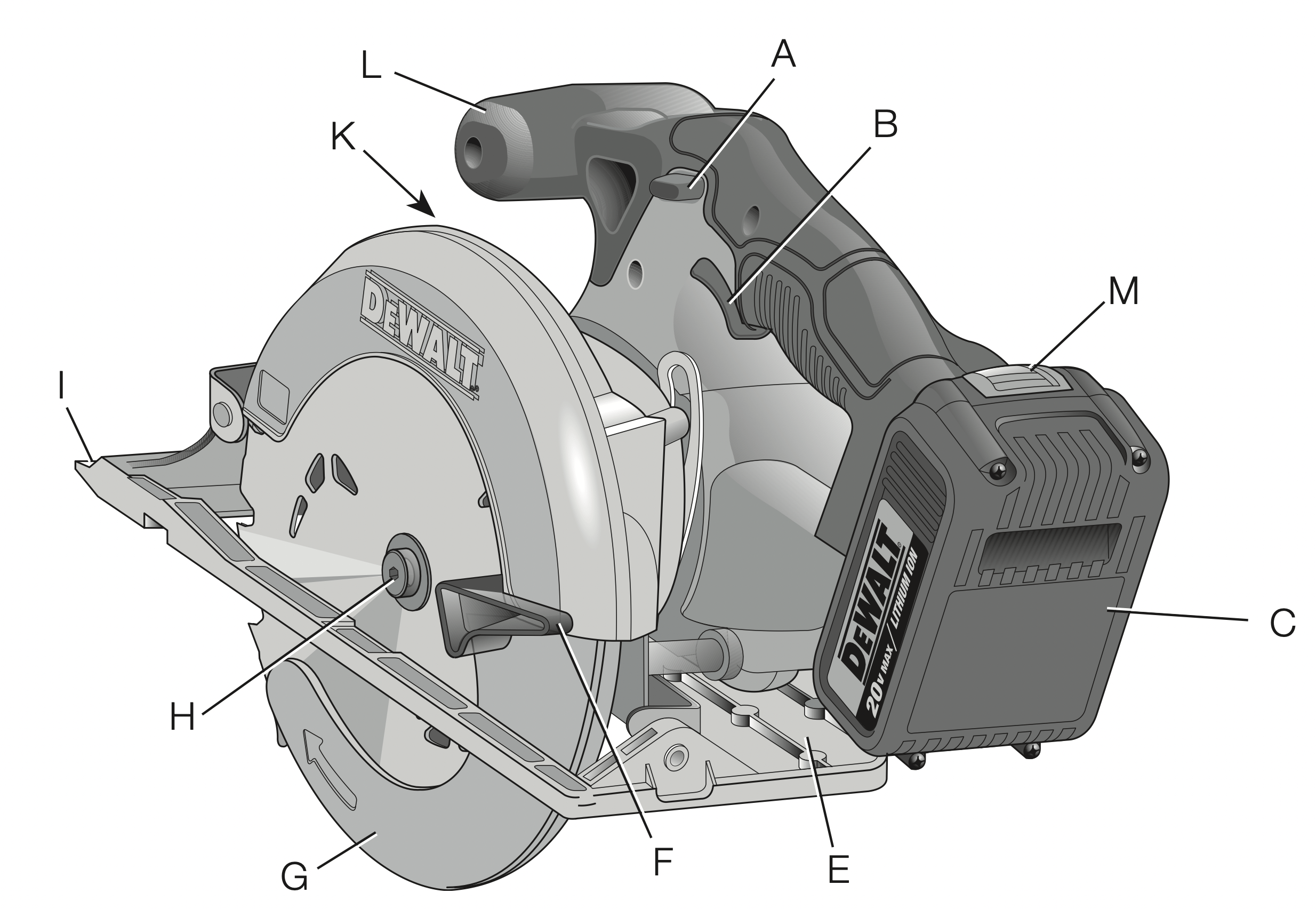
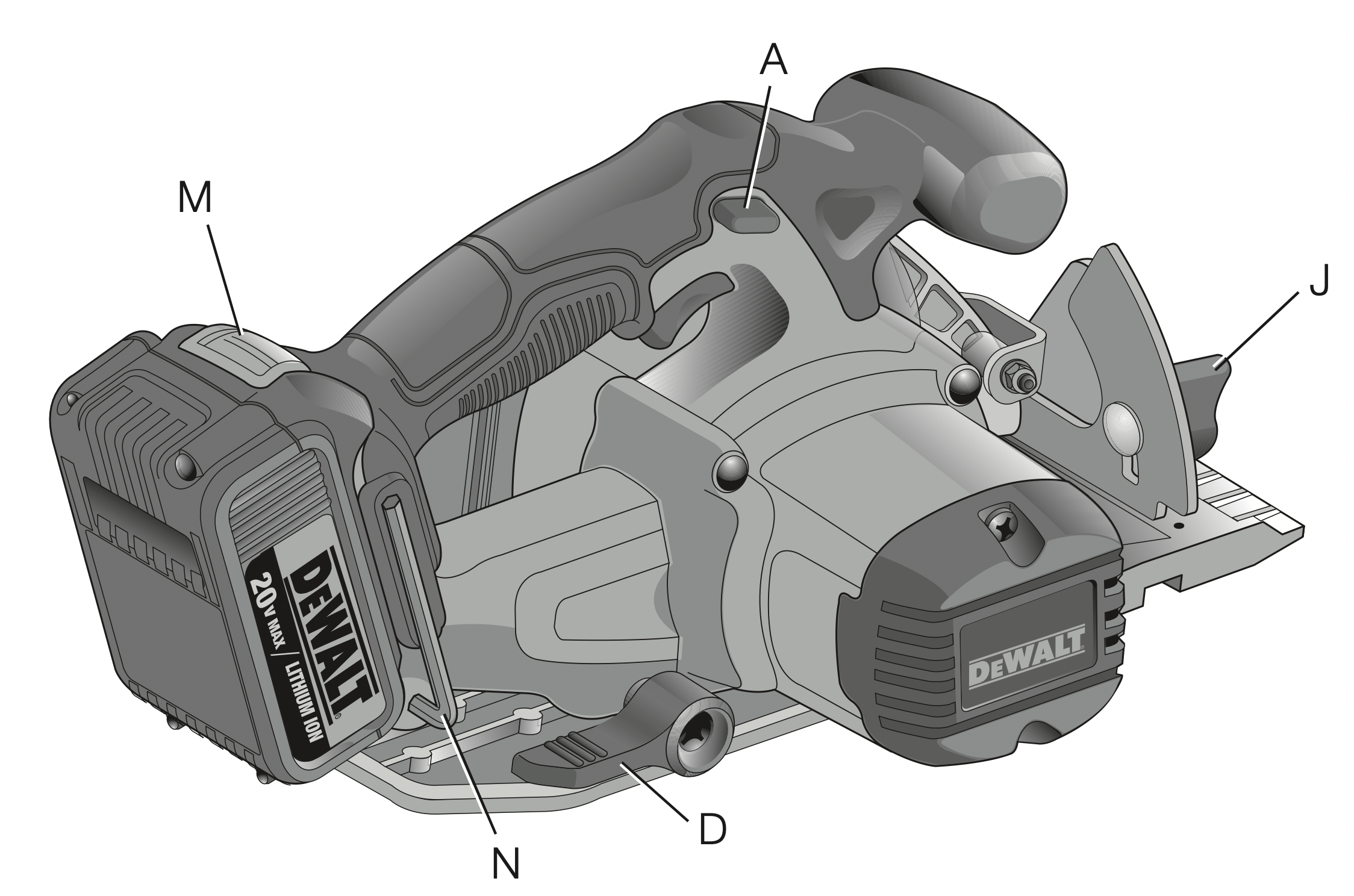
A. TRIGGER SWITCH LOCK-OFF BUTTON
B. TRIGGER SWITCH
C. BATTERY PACK
D. DEPTH ADJUSTMENT KNOB
E. SHOE
F. LOWER BLADE GUARD RETRACTING LEVER
G. LOWER BLADE GUARD
H. BLADE CLAMPING SCREW
I. KERF INDICATOR
J. BEVEL ADJUSTMENT KNOB
K. BLADE LOCK BUTTON (not shown)
L. AUXILIARY HANDLE
M. BATTERY RELEASE BUTTON
N. BLADE WRENCH
Chargers
Your tool uses a DEWALT charger. Be sure to read all safety instructions before using your charger. Consult the chart at the end of this manual for compatibility of chargers and battery packs.
Charging Procedure (Fig. 1)
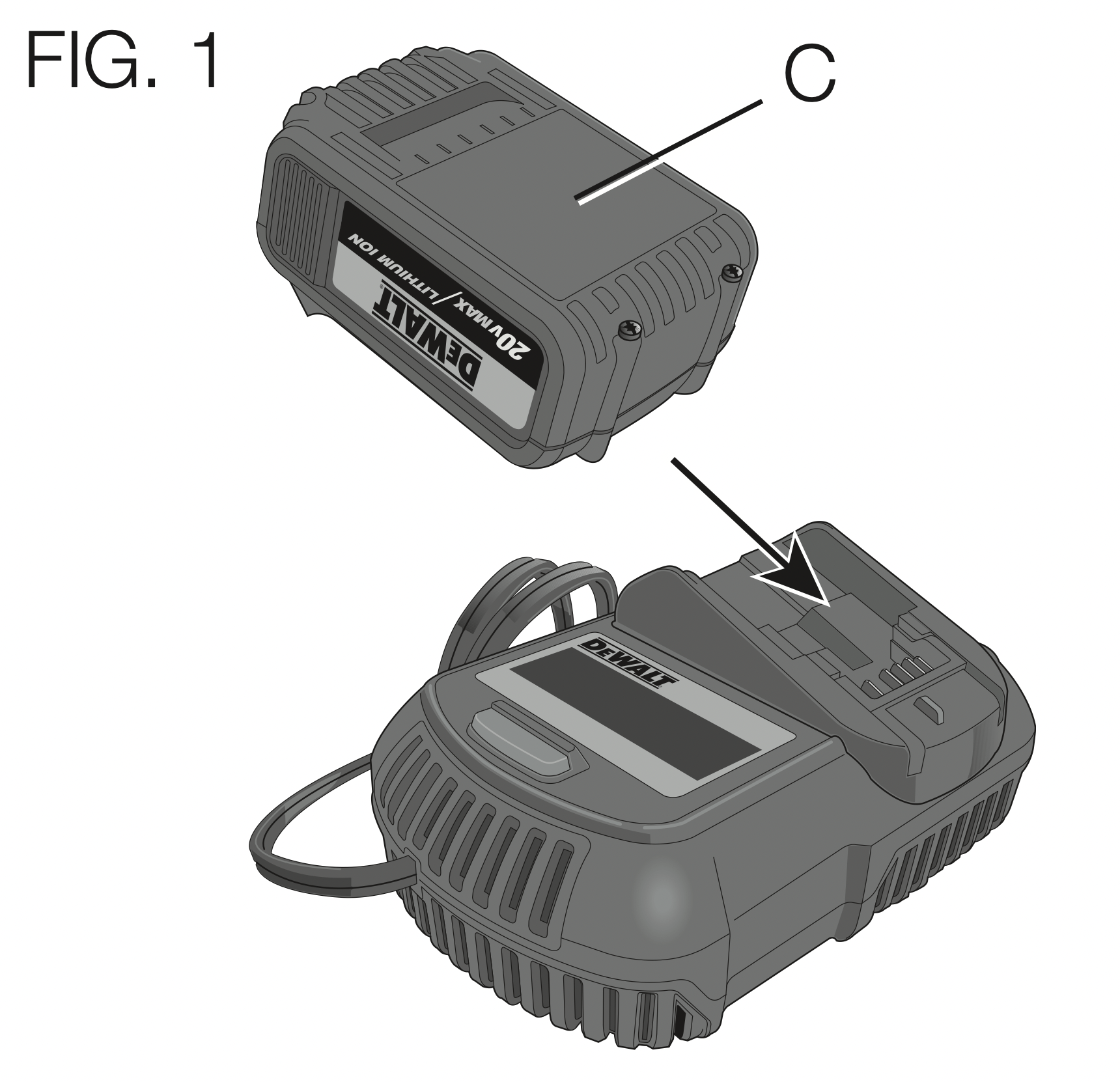
- Plug the charger into an appropriate outlet before inserting the battery pack.
- Insert the battery pack (C) into the charger, as shown in Figure 1, making sure the pack is fully seated in charger. The red (charging) light will blink continuously, indicating that the charging process has started.
- The completion of charge will be indicated by the red light remaining ON continuously. The pack is fully charged and may be used at this time or left in the charger.
Indicator Light Operation
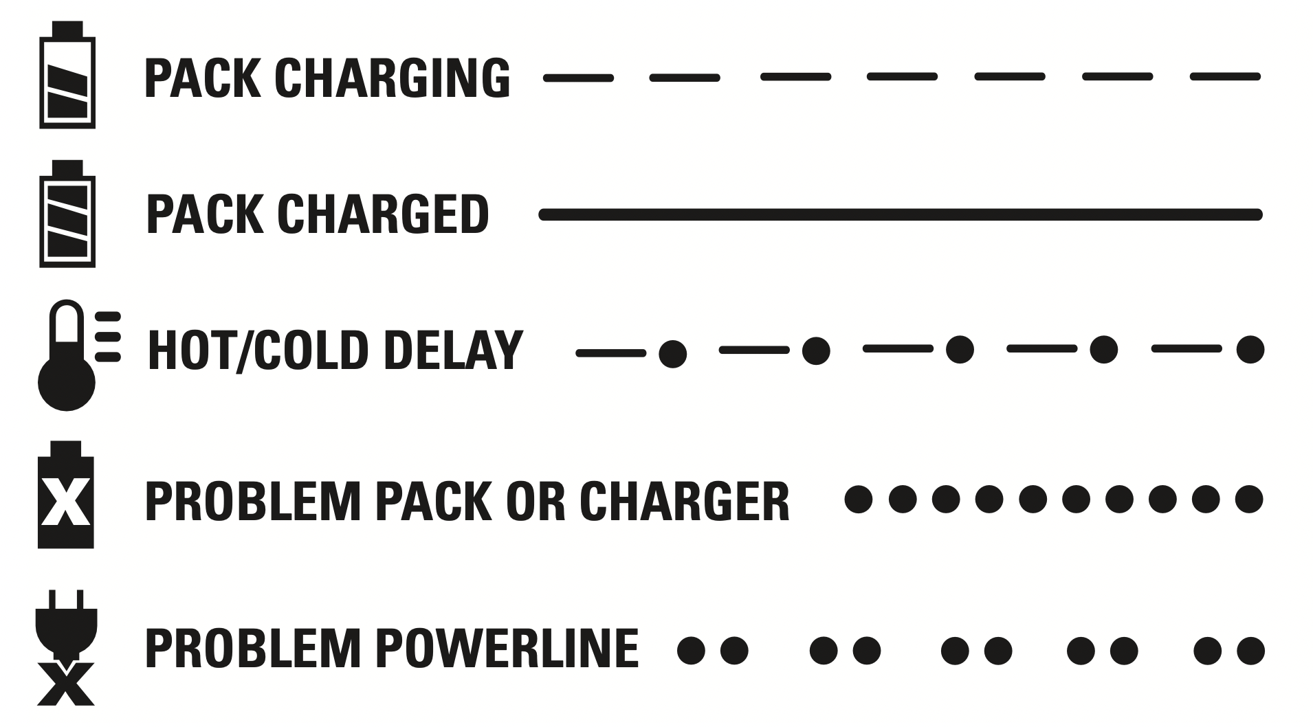
Charge Indicators
This charger is designed to detect certain problems that can arise. Problems are indicated by the red light flashing at a fast rate. If this occurs, re-insert the battery pack into the charger. If the problem persists, try a different battery pack to determine if the charger is working properly. If the new pack charges correctly, then the original pack is defective and should be returned to a service center or other collection site for recycling. If the new battery pack elicits the same trouble indication as the original, have the charger and the battery pack tested at an authorized service center.
HOT/COLD DELAY
This charger has a hot/cold delay feature: when the charger detects a battery that is hot, it automatically starts a delay, suspending charging until the battery has cooled. After the battery has cooled, the charger automatically switches to the pack charging mode. This feature ensures maximum battery life. The red light flashes long, then short while in the hot/cold delay mode.
LEAVING THE BATTERY PACK IN THE CHARGER
The charger and battery pack can be left connected with the charge indicator showing Pack Charged.
WEAK BATTERY PACKS: Weak batteries will continue to function but should not be expected to perform as much work.
FAULTY BATTERY PACKS: This charger will not charge a faulty battery pack. The charger will indicate faulty battery pack by refusing to light or by displaying problem pack or charger.
NOTE: This could also mean a problem with a charger.
PROBLEM POWER LINE
Some chargers have a problem powerline indicator. When the charger is used with some portable power sources such as generators or sources that convert DC to AC, the charger may temporarily suspend operation, flashing the red light with two fast blinks followed by a pause. This indicates the power source is out of limits.
COMPONENTS
WARNING: Never modify the power tool or any part of it. Damage or personal injury could result.
Please refer to the front of this section for the list of components.
INTENDED USE
This heavy-duty circular saw is designed for professional wood cutting applications.
DO NOT use under wet conditions or in presence of flammable liquids or gases.
DO NOT let children come into contact with the tool. Supervision is required when inexperienced operators use this tool.
OPERATION
WARNING: To reduce the risk of serious personal injury, turn tool off and disconnect tool from power source before making any adjustments or removing/installing attachments or accessories. An accidental start-up can cause injury.
Installing and Removing the Battery Pack (Fig. 2)

NOTE: For best results, make sure your battery pack is fully charged. To install the battery pack (C) into the tool handle, align the battery pack with the rails inside the tool’s handle and slide it into the handle until the battery pack is firmly seated in the tool and ensure that it does not disengage.
To remove the battery pack from the tool, press the release button (M) and firmly pull the battery pack out of the tool handle. Insert it into the charger as described in the charger section of this manual.
FUEL GAUGE BATTERY PACKS (FIG. 2A)
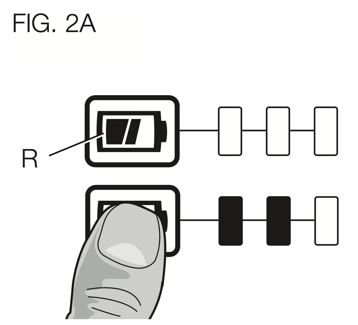
Some DEWALT battery packs include a fuel gauge which consists of three green LED lights that indicate the level of charge remaining in the battery pack.
To actuate the fuel gauge, press and hold the fuel gauge button (R).
A combination of the three green LED lights will illuminate designating the level of charge left. When the level of charge in the battery is below the usable limit, the fuel gauge will not illuminate and the battery will need to be recharged.
NOTE: The fuel gauge is only an indication of the charge left on the battery pack. It does not indicate tool functionality and is subject to variation based on product components, temperature and end-user application.
Trigger Switch (Fig. 3)
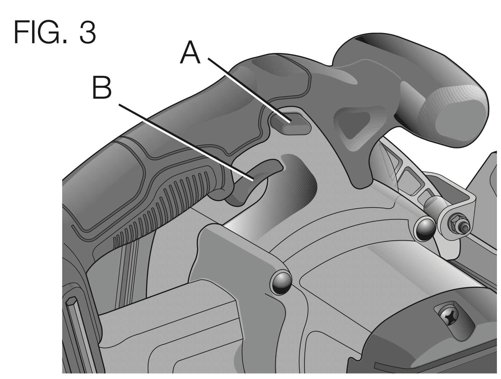
WARNING: This tool has no provision to lock the trigger switch in the ON position and should never be locked ON by any other means.
Release the trigger switch lock-off button (A) by pressing the button as shown. Pull the trigger switch (B) to turn the motor on. Releasing the trigger switch turns the motor off.
Changing Blades (Fig. 4, 5)
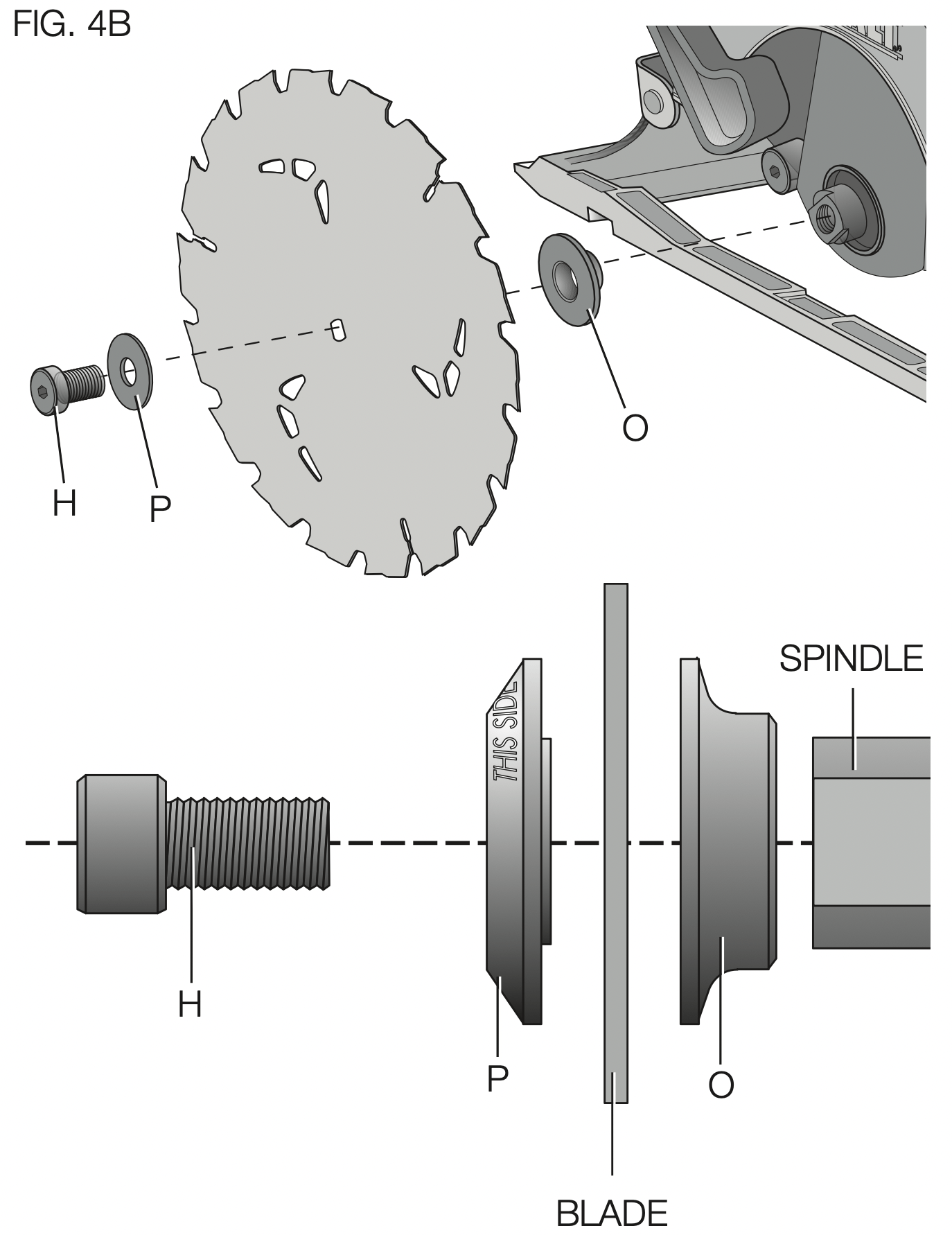
TO INSTALL THE BLADE (FIG. 4, 5)
- Place inner clamp washer (O) on saw spindle with the large flat surface facing out toward the blade (Fig. 4A, 4B).
- Retract the lower blade guard (G) and place blade on saw spindle against the inner clamp washer, making sure that the blade will rotate in the proper direction (the direction of the rotation arrow on the saw blade and the teeth must point in the same direction as the direction of rotation arrow on the lower blade guard). Do not assume that the printing on the blade will always be facing you when properly installed. When retracting the lower blade guard to install the blade, check the condition and operation of the lower blade guard to assure that it is working properly. Make sure it moves freely and does not touch the blade or any other part, in all angles and depths of cut.
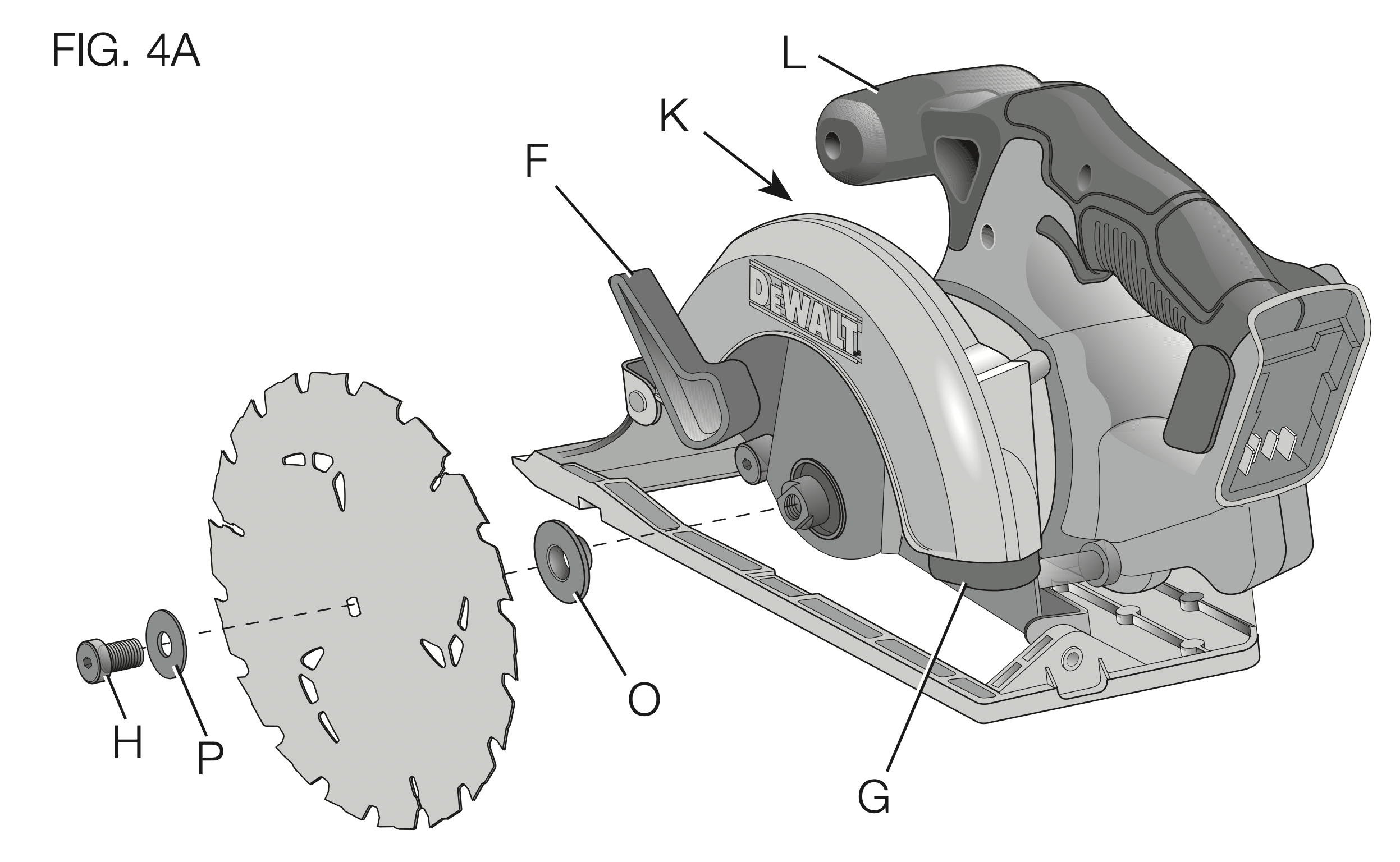
- Place outer clamp washer (P) on saw spindle with the large flat surface against the blade with beveled side facing out.
- Thread blade clamping screw (H) into saw spindle by hand (screw has left-hand threads and must be turned counterclockwise to tighten).
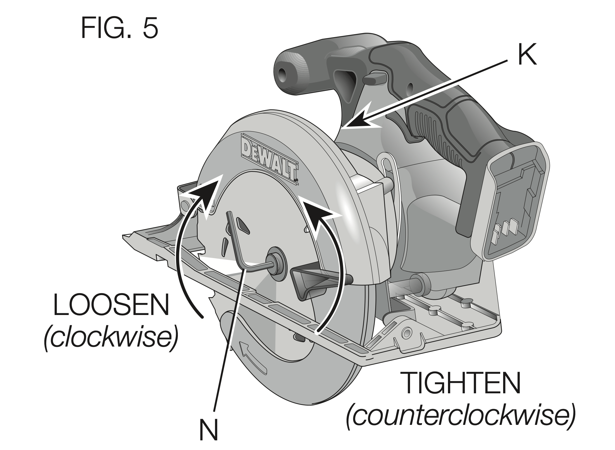
- Depress the blade lock button (K) while turning the saw spindle with the blade wrench (N) until the blade lock engages and the blade stops rotating (Fig. 5).
- Tighten the blade clamping screw firmly with the blade wrench.
NOTE: Never engage the blade lock while saw is running, or engage in an effort to stop the tool. Never turn the saw on while the blade lock is engaged. Serious damage to your saw will result.
TO REPLACE THE BLADE (FIG. 4, 5)
- To loosen the blade clamping screw (H), depress the blade lock button (K) and turn the saw spindle with the blade wrench (N) until the blade lock engages and the blade stops rotating. With the blade lock engaged, turn the blade clamping screw clockwise with the blade wrench (screw has left-hand threads and must be turned clockwise to loosen).
- Remove the blade clamping screw (H) and outer clamp washer (P) only. Remove old blade.
- Clean any sawdust that may have accumulated in the guard or clamp washer area and check the condition and operation of the lower blade guard as previously outlined. Do not lubricate this area.
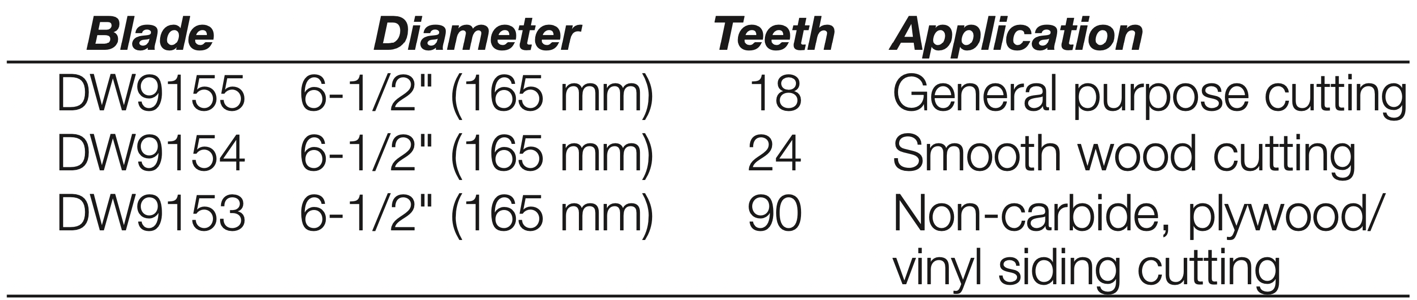
- Select the proper blade for the application (see Blades). Always use blades that are the correct size (diameter) with the proper size and shape center hole for mounting on the saw spindle. Always assure that the maximum recommended speed (rpm) on the saw blade meets or exceeds the speed (rpm) of the saw.
- Follow steps 2 through 6 under To Install the Blade, making sure that the blade will rotate in the proper direction.
LOWER BLADE GUARD
WARNING: The lower blade guard is a safety feature which reduces the risk of serious personal injury. Never use the saw if the lower blade guard is missing, damaged, misassembled or not working properly. Do not rely on the lower blade guard to protect you under all circumstances. Your safety depends on following all warnings and precautions as well as proper operation of the saw. Check lower blade guard for proper closing before each use as outlined in Further Safety Instructions for All Saws. If the lower blade guard is missing or not working properly, have the saw serviced before using. To assure product safety and reliability, repair, maintenance and adjustment should be performed by an authorized service center or other qualified service organization, always using identical replacement parts.
Blades
WARNING: To minimize the risk of eye injury, always use eye protection. Carbide is a hard but brittle material. Foreign objects in the workpiece such as wire or nails can cause tips to crack or break. Only operate saw when proper saw blade guard is in place. Mount blade securely in proper rotation before using, and always use a clean, sharp blade.
WARNING: Do not cut ferrous metals (steel), masonry, glass, masonry-type planking, cement board or tile with this saw.
Do not use abrasive wheels or blades. A dull blade will cause slow inefficient cutting, overload on the saw motor, excessive splintering, and could increase the possibility of kickback. Please refer to the table below to determine the correct size replacement blade for your model saw.
KICKBACK
Kickback is a sudden reaction to a pinched, bound or misaligned saw blade, causing an uncontrolled saw to lift up and out of the workpiece toward the operator. When the blade is pinched or bound tightly by the kerf closing down, the blade stalls and the motor reaction drives the unit rapidly back toward the operator. If the blade becomes twisted or misaligned in the cut, the teeth at the back edge of the blade can dig into the top surface of the wood causing the blade to climb out of the kerf and jump back toward the operator.
Kickback is more likely to occur when any of the following conditions exists.
- IMPROPER WORKPIECE SUPPORT
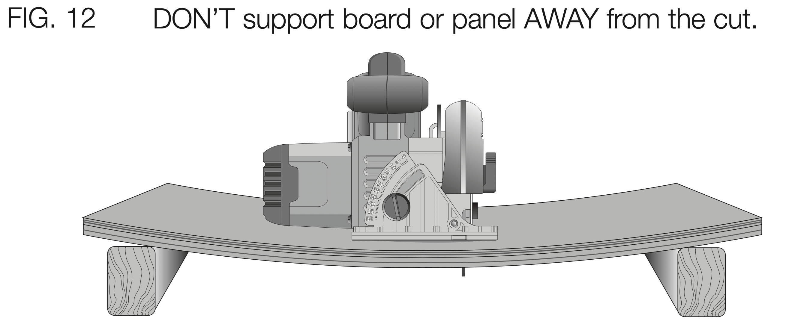
A. Sagging or improper lifting of the cut off piece can cause pinching of the blade and lead to kickback (Fig. 12).
B. Cutting through material supported at the outer ends only can cause kickback. As the material weakens it sags, closing down the kerf and pinching the blade (Fig. 12).
C. Cutting off a cantilevered or overhanging piece of material from the bottom up in a vertical direction can cause kickback. The falling cut off piece can pinch the blade.
D. Cutting off long narrow strips (as in ripping) can cause kickback.
The cut off strip can sag or twist closing the kerf and pinching the blade.
E. Snagging the lower guard on a surface below the material being cut momentarily reduces operator control. The saw can lift partially out of the cut increasing the chance of blade twist.
- IMPROPER DEPTH OF CUT SETTING ON SAW
To make the most efficient cut, the blade should protrude only far enough to expose one-half of a tooth as shown in Figure 7. This allows the shoe to support the blade and minimizes twisting and pinching in the material. See the section titled Cutting Depth Adjustment.
- BLADE TWISTING (MISALIGNMENT IN CUT)
A. Pushing harder to cut through a knot, a nail, or a hard grain area can cause the blade to twist.
B. Trying to turn the saw in the cut (trying to get back on the marked line) can cause blade twist.
C. Overreaching or operating the saw with poor body control (out of balance), can result in twisting the blade.
D. Changing hand grip or body position while cutting can result in blade twist.
E. Backing up the saw to clear blade can lead to twist.
- MATERIALS THAT REQUIRE EXTRA ATTENTION
A. Wet lumber
B. Green lumber (material freshly cut or not kiln dried)
C. Pressure treated lumber (material treated with preservatives or anti-rot chemicals)
- USE OF DULL OR DIRTY BLADES
Dull blades cause increased loading of the saw. To compensate, an operator will usually push harder which further loads the unit and promotes twisting of the blade in the kerf. Worn blades may also have insufficient body clearance which increases the chance of binding and increased loading.
- LIFTING THE SAW WHEN MAKING A BEVEL CUT
Bevel cuts require special operator attention to proper cutting techniques – especially guidance of the saw. Both blade angle to the shoe and greater blade surface in the material increase the chance for binding and misalignment (twist) to occur.
- RESTARTING A CUT WITH THE BLADE TEETH JAMMED AGAINST THE MATERIAL
The saw should be brought up to full operating speed before starting a cut or restarting a cut after the unit has been stopped with the blade in the kerf. Failure to do so can cause stalling and kickback.
Any other conditions which could result in pinching, binding, twisting, or misalignment of the blade could cause kickback. Refer to the sections Further Safety Instructions for All Saws and Blades for procedures and techniques that will minimize the occurrence of kickback.
Cutting Depth Adjustment (Fig. 6, 7)
- Hold the saw firmly and loosen (clockwise) the depth adjustment knob (D) and move shoe to obtain the desired depth of cut.
- Make sure the depth adjustment knob has been retightened (counterclockwise) before operating saw.
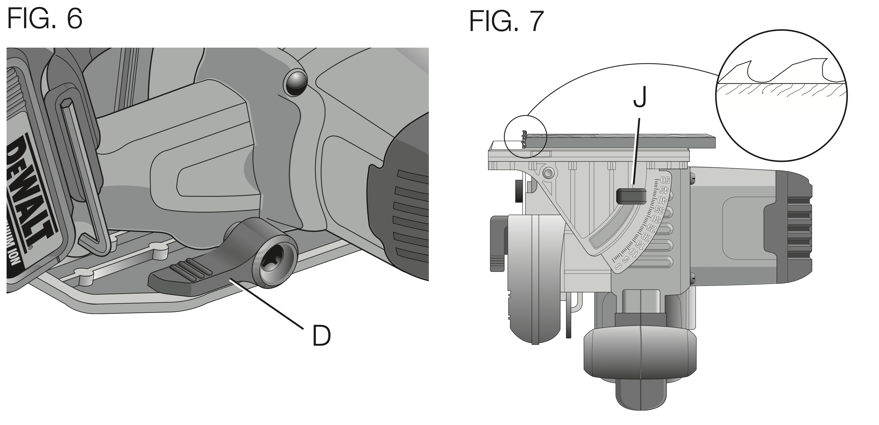
For the most efficient cutting action, set the depth adjustment so that one-half tooth of the blade will project below the material to be cut. This distance is from the tip of the tooth to the bottom of the gullet in front of it. This keeps blade friction at a minimum, removes sawdust from the cut, results in cooler, faster sawing and reduces the chance of kickback. A method for checking for correct cutting depth is shown in Figure 7. Lay a piece of the material you plan to cut along the side of the blade, as shown, and observe how much tooth projects beyond the material.
Bevel Angle Adjustment (Fig. 7)
The full range of the bevel adjustment is from 0° to 50°. The quadrant is graduated in increments of 1°. On the front of the saw is a bevel angle adjustment mechanism consisting of a calibrated quadrant and a bevel adjustment knob (J).
TO SET THE SAW FOR A BEVEL CUT
- Loosen (counterclockwise) the bevel adjustment knob (J) and tilt shoe to the desired angle by aligning the pointer with the desired angle mark.
- Retighten knob firmly (clockwise).
Shoe Adjustment for 90°Cuts (Fig. 8)
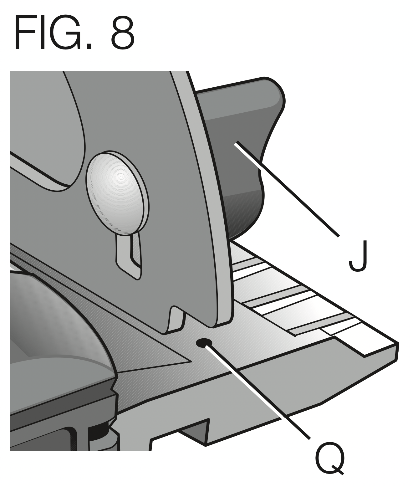
IF ADDITIONAL ADJUSTMENT IS NEEDED:
- Adjust the saw to 0° bevel.
- Retract the lower blade guard. Place the saw on blade side.
- Loosen bevel adjustment knob (J). Place a square against the blade and shoe to adjust the 90° setting.
- Turn the calibration screw (Q) so that the shoe will stop at the proper angle.
- Confirm the accuracy of the setting by checking the squareness of an actual cut on a scrap piece of material.
Kerf Indicator (Fig. 9)
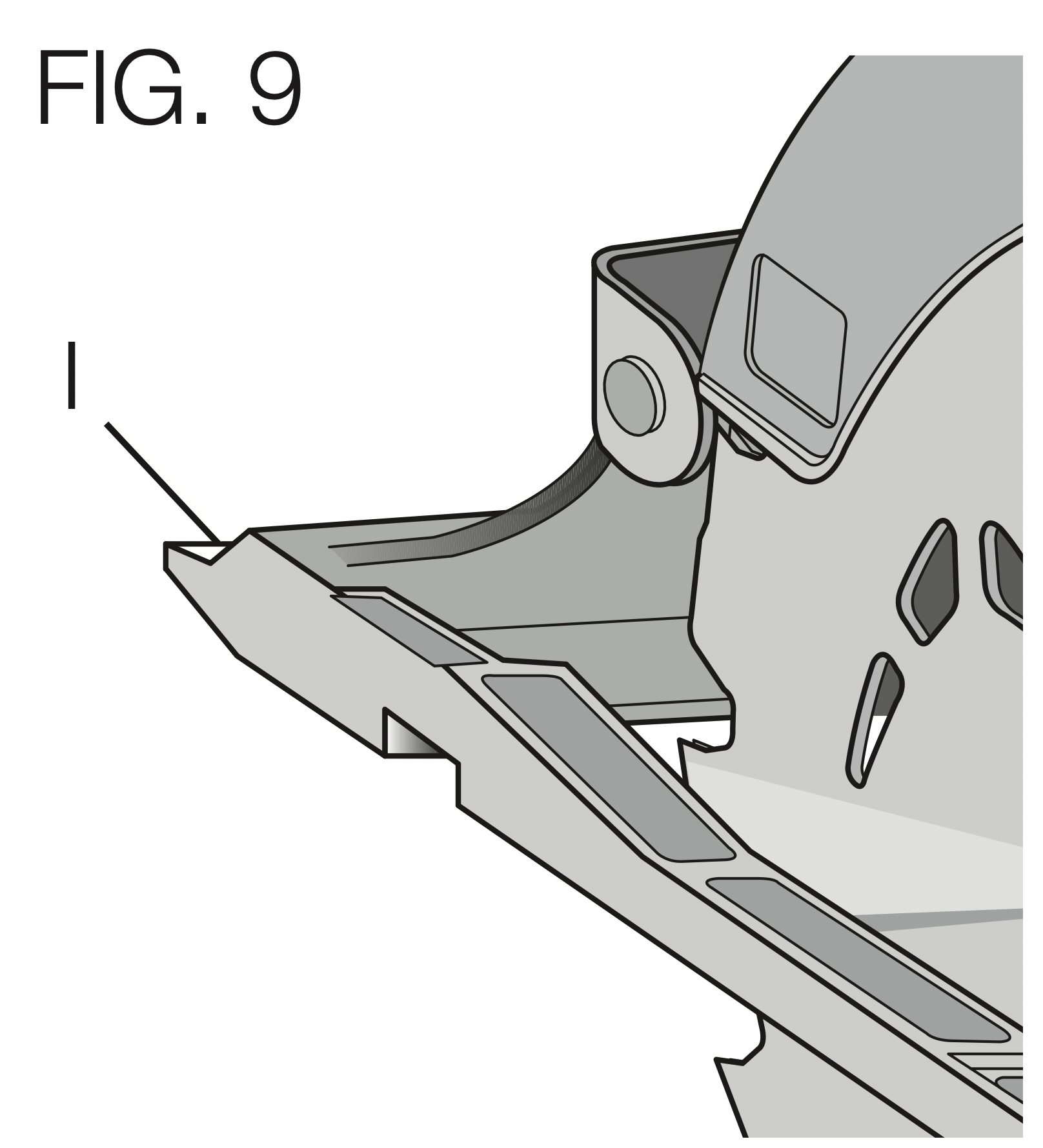
The front of the saw shoe has a kerf indicator (I) for vertical and bevel cutting. This indicator enables you to guide the saw along cutting lines penciled on the material being cut. The kerf indicator lines up with the left (outer) side of the saw blade, which makes the slot or “kerf” cut by the moving blade fall to the right of the indicator. Guide along the penciled cutting line so that the kerf falls into the waste or surplus material.
Workpiece Support (Fig. 10–12)
WARNING: It is important to support the work properly and to hold the saw firmly to prevent loss of control which could cause personal injury. Figure 10 illustrates proper hand support of the saw. Maintain a firm grip with both hands on the saw and position your body and arm to allow you to resist kickback if it occurs. ALWAYS TURN OFF TOOL AND REMOVE BATTERY BEFORE MAKING ANY ADJUSTMENTS!
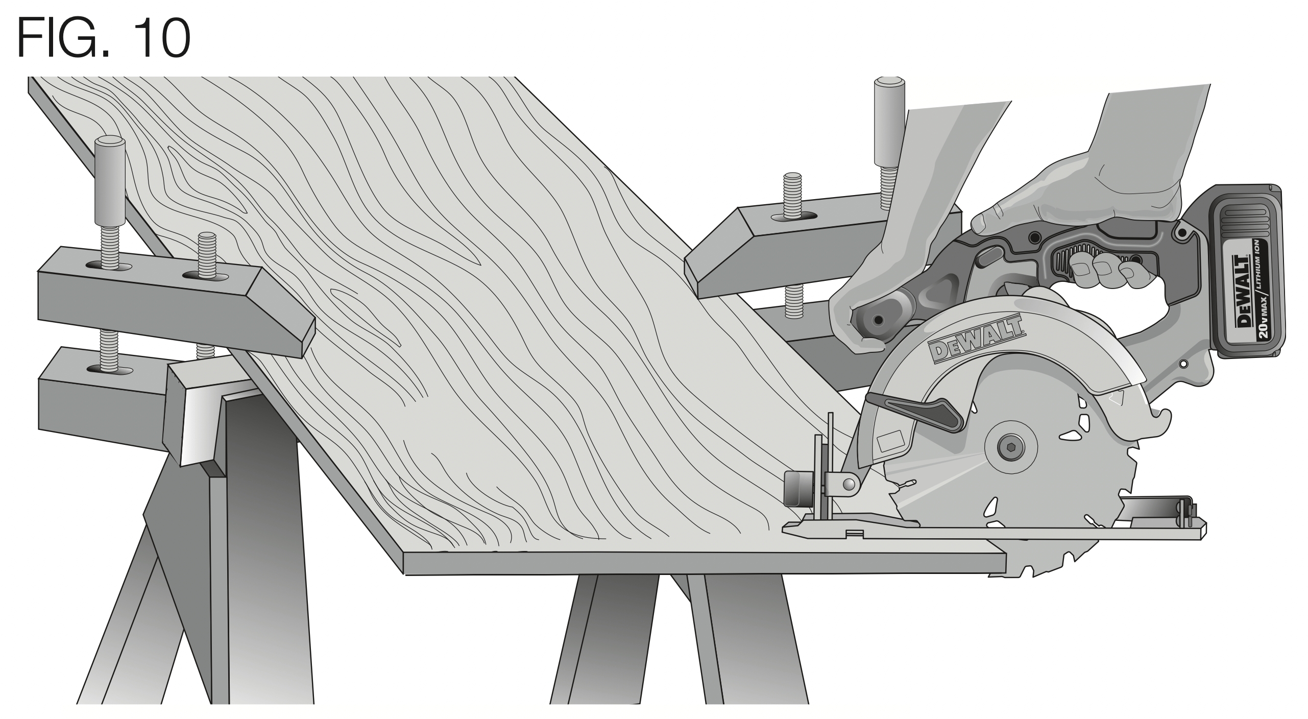
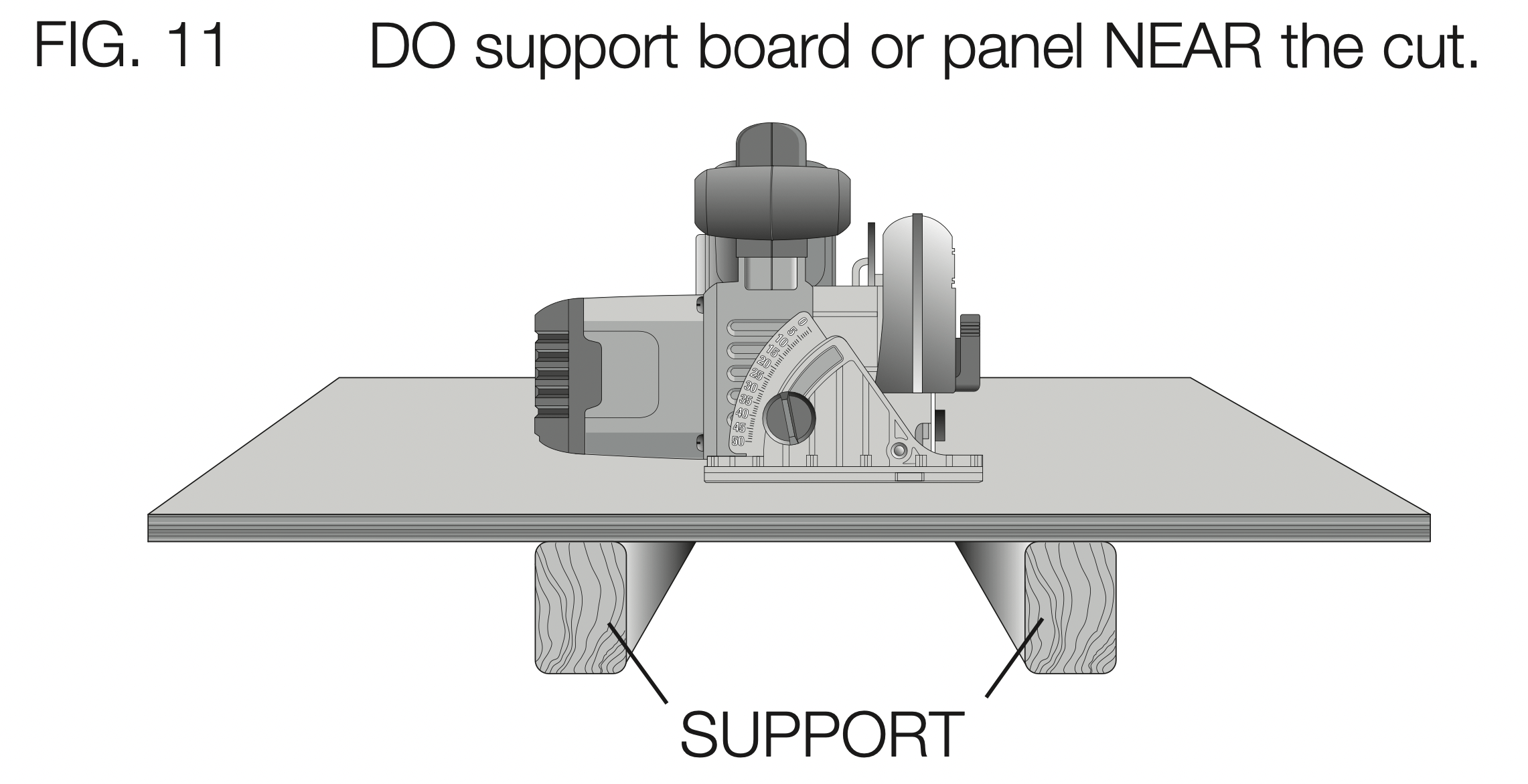
Figure 10 shows proper sawing position. Note that hands are kept away from cutting area. To avoid kickback, DO support board or panel NEAR the cut (Fig. 11). DON’T support board or panel away from the cut (Fig. 12).
Place the work with its “good” side – the one on which appearance is most important – down. The saw cuts upward, so any splintering will be on the work face that is up when you cut it.
Cutting (Fig. 10)
Place the wider portion of the saw shoe on that part of the workpiece which is solidly supported, not on the section that will fall off when the cut is made. As an example, Figure 10 illustrates the RIGHT way to cut off the end of a board. Always clamp work. Don’t try to hold short pieces by hand! Remember to support cantilevered and overhanging material. Use caution when sawing material from below.
Be sure saw is up to full speed before blade contacts material to be cut. Starting saw with blade against material to be cut or pushed forward into kerf can result in kickback. Push the saw forward at a speed which allows the blade to cut without laboring.
Hardness and toughness can vary even in the same piece of material, and knotty or damp sections can put a heavy load on the saw. When this happens, push the saw more slowly, but hard enough to keep working without much decrease in speed. Forcing the saw can cause rough cuts, inaccuracy, kickback, and over-heating of the motor.
Should your cut begin to go off the line, don’t try to force it back on. Release the trigger switch and allow blade to come to a complete stop. Then you can withdraw the saw, sight anew, and start a new cut slightly inside the wrong one. Withdraw the saw if you must shift the cut. Forcing a correction inside the cut can stall the saw and lead to kickback.
IF SAW STALLS, RELEASE THE TRIGGER SWITCH AND BACK THE SAW UNTIL IT IS LOOSE. BE SURE BLADE IS STRAIGHT IN THE CUT AND CLEAR OF THE CUTTING EDGE BEFORE RESTARTING.
As you finish a cut, release the trigger switch and allow the blade to stop before lifting the saw from the work. As you lift the saw, the spring-tensioned lower blade guard will automatically close under the blade. Remember the blade is exposed until this occurs. Never reach under the work for any reason. When you have to retract the lower blade guard manually (as is necessary for starting pocket cuts), always use the retracting lever.
WARNING: When cutting thin strips, be careful to ensure that small cutoff pieces don’t hang up on the inside of the lower blade guard.
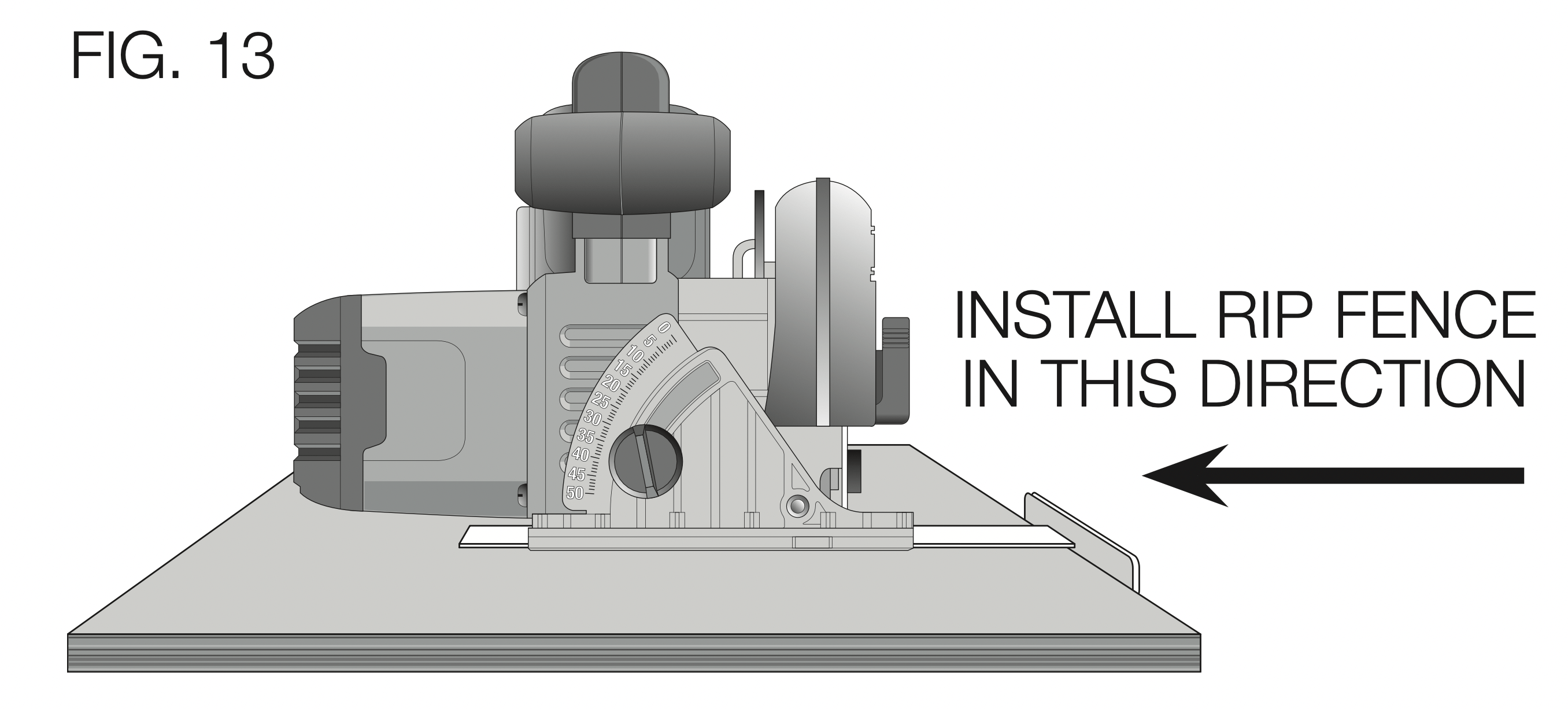
RIPPING (FIG. 13)
Ripping is the process of cutting wider boards into narrower strips cutting grain lengthwise. Hand guiding is more difficult for this type of sawing and the use of a DEWALT rip fence is recommended.
POCKET CUTTING (FIG. 14)
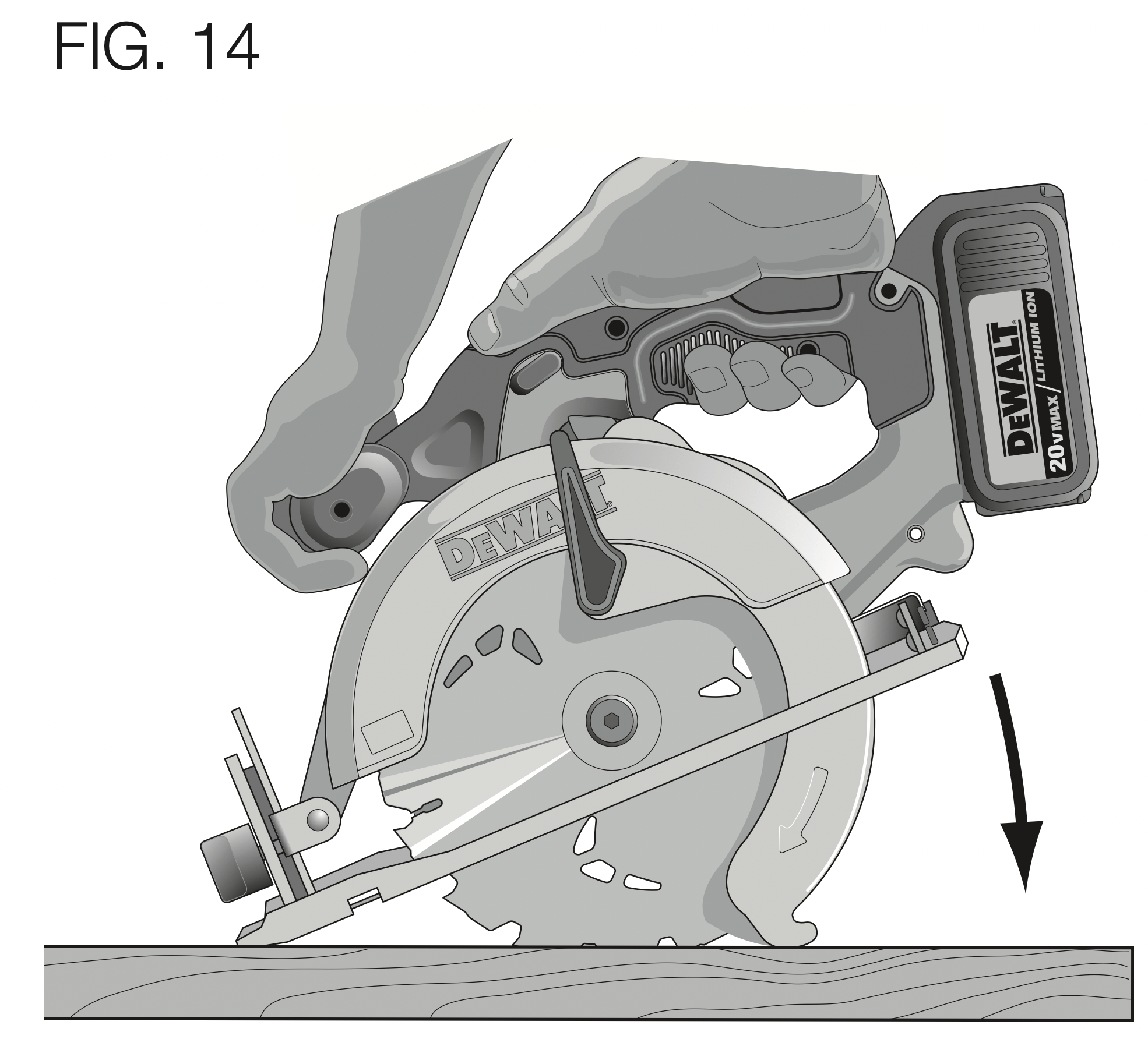
WARNING: Never tie the lower blade guard in a raised position. Never move the saw backwards when pocket cutting. This may cause the saw to raise up off the work surface, which could cause injury.
A pocket cut is one that is made in a floor, wall or other flat surface.
- Adjust the saw shoe so the blade cuts at desired depth.
- Tilt the saw forward and rest front of the shoe on material to be cut.
- Using the lower blade guard retracting lever, retract the lower blade guard to an upward position. Lower the rear of the shoe until the blade teeth almost touch the cutting line.
- Release the lower blade guard (its contact with the work will keep it in position to open freely as you start the cut). Remove your hand from the lower blade guard retracting lever and firmly grip the auxiliary handle, as shown in Figure 14. Position your body and arm to allow you to resist kickback if it occurs.
- Make sure blade is not in contact with cutting surface before starting saw.
- Start the motor and gradually lower the saw until its shoe rests flat on the material to be cut. Advance saw along the cutting line until cut is completed.
- Release the trigger switch and allow the blade to stop completely before withdrawing the blade from the material.
- When starting each new cut, repeat the above steps.
MAINTENANCE
WARNING: To reduce the risk of serious personal injury, turn tool off and disconnect tool from power source before making any adjustments or removing/installing attachments or accessories. An accidental start-up can cause injury.
Cleaning
WARNING: Blow dirt and dust out of all air vents with clean, dry air at least once a week. To minimize the risk of eye injury, always wear ANSI Z87.1 approved eye protection when performing this.
WARNING: Never use solvents or other harsh chemicals for cleaning the non-metallic parts of the tool. These chemicals may weaken the plastic materials used in these parts. Use a cloth dampened only with water and mild soap. Never let any liquid get inside the tool; never immerse any part of the tool into a liquid.
CHARGER CLEANING INSTRUCTIONS
WARNING: Shock hazard. Disconnect the charger from the AC outlet before cleaning. Dirt and grease may be removed from the exterior of the charger using a cloth or soft non-metallic brush. Do not use water or any cleaning solutions.
Lubrication
Self lubricating ball and roller bearings are used in the tool and relubrication is not required. However, it is recommended that, once a year, you take or send the tool to a certified service center for a thorough cleaning, inspection, and lubrication of the gear case.
Accessories
WARNING: Since accessories, other than those offered by DEWALT, have not been tested with this product, use of such accessories with this tool could be hazardous. To reduce the risk of injury, only DEWALT recommended accessories should be used with this product.
Recommended accessories for use with your tool are available at extra cost from your local service center. If you need any assistance in locating any accessory, please contact DEWALT Industrial Tool Co., 701 East Joppa Road, Baltimore, MD 21286, call 1-800-4-DEWALT (1-800-433-9258) or visit our website: www.dewalt.com.
Repairs
The charger and battery pack are not serviceable. There are no serviceable parts inside the charger or battery pack.
To assure product SAFETY and RELIABILITY, repairs, maintenance and adjustments (including brush inspection and replacement) should be performed by a DEWALT factory service center, a DEWALT authorized service center or other qualified service personnel. Always use identical replacement parts.