Your tool uses a DEWALT charger. Be sure to read all safety instructions before using your charger. Consuft he chart at the end of this manual for compatibity of chargers and battery packs.
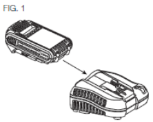
Charging Procedure (Fig. 1)
Plug the charger into an appropriate outiet before inserting the battery pack.
Insert the battery pack into the charger. as shown
The completion of charge will be indicated by the red light remaining ON continuously. The pack is fully charged and may be used at this time or left in the charger.
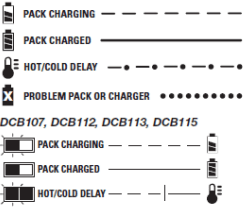
Indicator Light Operation
DCB101, DCB102, DCB103
Charge Indicators
This charger is designed to detect the red light flashing at a fast rate. If this occns, re-insert the battery pack into the charger. If the problem persists, try a different battery pack to determine if the charger is working properly. If the new pack charges correctly, then the original pack is defective and should be returned to a service center or other collection site for recycling. If the new battery pack elicits the same trouble indication as the original, have the charger and the battery pack tested at an authorized service center.
HOT/COLD DELAY
DCB101, DCB102. DCB103
These chargers have a hot/cdd delay feature. When the charger detects a battery that is too hot or too cold, it automatically starts a delay, suspending charging. The red light flashes long, then short while in the hot/cdd delay mode.
Once the battery has reached an optimum temperatue, the charger will automatically resume the chargng procedure. This feature ensures maximum battery life.
DCB107, DCB112, DCB113, DCB115
These chargers have a hot/cdd delay feature. When the charger detects a battery that is too hot or too cold, it automatically starts a delay, suspending charging. The red light will continue to blink, but a yellow indicator light will be illuminated during this suspension.
Once the battery has reached an optimum temperature, the yellow light wil turn off and the charger will automaflcaty resume the charging procedire This feature ensures maximum battery life.
LEAVING THE BATTERY PACK IN THE CHARGER
The charger and battery pack can be left connected with the charge indicator showing Pack Charged.
WEAK BATTERY PACKS: Weak batteries will continue to function but should not be expected to perform as much work.
FAULTY BATTERY PACKS
DCB101, DCB102. DCB103
These chargers will not charge a faulty battery pack. The charger will indicate faiJty battery pack by refusing to light or by displaying problem pack or charger.
NOTE: This codd also mean a problem with a charger.
DCB107, DCB112, DCB113, DCB115
These chargers will not charge a fadty battery pack. The charger will indicate faulty battery pack by refusing to light.
NOTE: This coUd also mean a problem with a charger.
Wall Mounting
DCB107, DCB112, DCB113, DCB115
These chargers are designed to be wall mountable or to sit upright on a table or work surface. If wall mounting, locate the charger within reach of an electrical outlet. Mount the charger securely using drywall screws at least 1" (25.4 mm) long, screwed into wood to an optimal depth leaving approximately 7732" (5.5 mm) of the screw exposed.
Important Charging Notes
Longest life and best performance can be obtained if the battery pack is charged when the air temperature is between 65 °F and 75 °F (18°-24 °Q. DO NOT charge the battery pack in an air temperature below +40 °F (+4.5 °Q, or above +104 °F (+40 °Q. This is important and will prevent serious damage to the battery pack.
The charger and battery pack may become warm to the touch while charging. This is a normal condition, and does not indicate a problem. To facilitate the coding of the battery pack after use, avoid placing the charger or battery pack in a warm environment such as in a metal shed or an uninsulated trailer.
A cold battery pack will charge at about half the rate of a warm battery pack. The battery pack will charge at that slower rate throughout the entire charging cycle and will not return to maximum charge rate even if the battery pack warms.
If the battery pack does not charge property:
a. Check operation of receptacle by plugging in a lamp or other appliance:
b. Check to see if receptacle is connected to a light switch which turns power off when you turn out the lights:
c. Move the charger and battery pack to a location where the surrounding air temperature is approximately 65 °F-75 °F (18°-24 °C);
d. If chargng problems persist, take the tod, battery pack and charger to your local service center.
5. The battery pack should be recharged when it fails to produce sufficient power on jobs which were easily done previously. DO NOT CONTINUE to use under these conditions. Follow the charging procedure. You may also charge a partially used pack whenever you desire with no adverse effect on the battery pack.
6. Foreign materials of a conductive nature such as, but not limited to, grinding dust, metal chips, steel wod. aluminum foil, or any buildup of metallic particles should be kept away from charger cavities. Always unplug the charger from the power sgcply when there is no battery pack in the cavity. Unplug the charger before attempting to dean.
7. Do not freeze or immerse the charger in water or any other liquid.
WARNING: Shock hazard. Don't aSow any Squid to get inside the charger. Electric shock may result.
WARNING: Bum hazard. Do not submerge the battery pack in any Squid or allow any liquid to enter the battery pack. Never attempt to open the battery pack tor any reason. If the plastic housing of the battery pack breaks or cracks, return to a service center for recycSng.
Storage Recommendations
The best storage place is one that is cod and dry, away from direct sunlight and excess heat orcdd.
For long storage, it is recommended to store a fully charged battery pack in a ood dry place out of the charger for optimal results.
NOTE: Battery packs should not be stored completely depleted of charge. The battery pack will need to be recharged before use.
SAVE THESE INSTRUCTIONS FOR FUTURE USE
Unpacking Your Saw
Check the contents of your miter saw carton to make sure that you have received all parts. In addition to this instruction manual, the carton should contain:
This heavy duty miter saw is designed for professional wood cutting applications.
DO NOT use under wet conditions or in presence of flammable liquids or gases.
This miter saw is a professional power tool. DO NOT let children come into contact with the tool. Supervision is required when inexperienced operators use this tool.
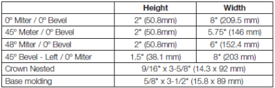
Specifications
CAPACITY OF CUT
NOTE: Your saw is capable of cutting the following once a special setup procedure is followed. Refer to Special Cuts.
Familiarization (Fig. 2, 3)
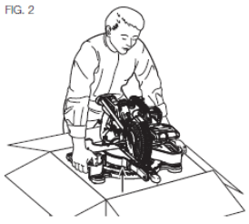
Your miter saw is fully assembled in the carton. Open the box and lift the saw out either by using the lilting handle (O) or by the hand indentations (J) h the base of the saw (Fig. 2)
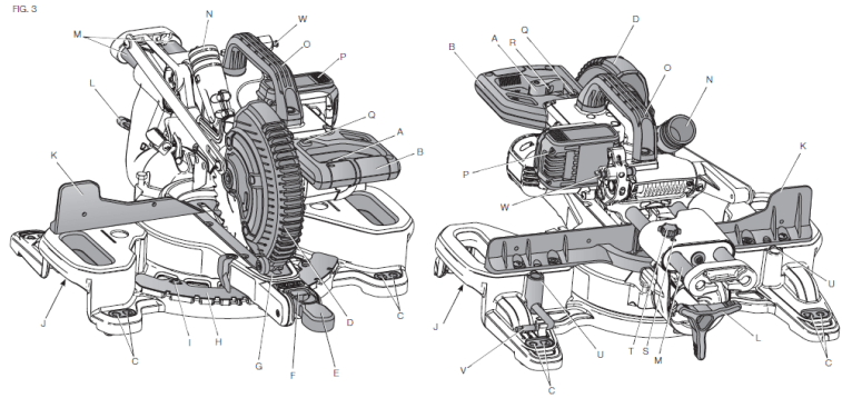
Place the saw on a smooth, flat surface such as a workbench or strong table. Examine figure 3 to beoome familiar with the saw and its various parts. The section on aqustments will refer to these terms and you must know what and where the parts are.
CAUTION: Pinch hazard. To reduce the risk of injury, keep thumb underneath the operating handle when pulling the handle down. The lower guard will move up as the operating handle is pulled down, which could cause pinching. The operating handle is placed close to the guard for special cuts.
Press down lightly on the operating handle (B) and pull out the lock down pin (W). Gently release the downward pressure and hold the operating hande, allowing it to rise to its full height. Use the lock down pin when carrying the saw from one place to another. Always use the hand indentations (J) to transport the saw as seen in figure 3.
Bench Mounting (Fig. 3)
Holes <C) are provided in all 4 feet to facilitate bench mounting, as shown in Figure 3. (Two different-sized holes are provided to accommodate different sizes of screws. Use either hole, it is not necessary to use both.) Always mount your saw firmly to a stable surface to prevent movement To enhance the tool's portability, it can be moulted to a piece of 1/2" (12.7 mm) or thicker plywood which can then be clamped to your work support or moved to other job sites and reclamped.
NOTE: If you elect to mount you saw to a piece of plywood, make sue that the mounting screws don't protrude from the bottom of the wood. The plywood must sit flush on the work support. When clamping the saw to any work surface, damp only on the damping bosses where the mounting screw holes are located. Clamping at any other point will interfere with the proper operation of the saw.
CAUTION: To prevent binding and inaccuracy, be sure the mounting surface is not warped or otherwise uneven. If the saw rocks on the surface, place a tNn piece of material under one saw foot urrtti the saw sits firmly on the mounting surface.
COMPONENTS (Fig. 3)
A. Trigger switch
B Operating handle
C Mounting holes
D Lower guard
E Miter lock knob
F Miter latch button
G Kerf plate
H Miter scale
I Miter scale screws
J Hand indentations
K Fence
L Bevel lock knob
M Flails
N Dust port
O Ufting hande
P Battery pack
Q. XPS™ worklight momentary switch
R. Lock off lever
S. Rail adjustment screw
T. Rail lock knob
U. Clamp mounting hole
V. Blade wrench
W. Lock down pin
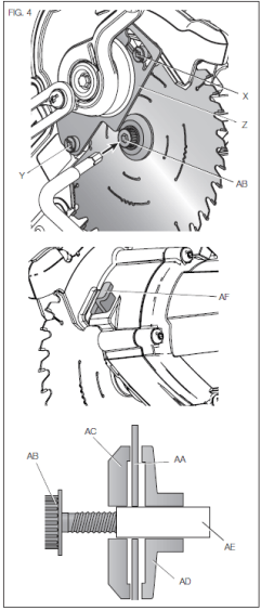
Changing or Installing a New Saw Blade (Fig. 4)
Refer to Saw Blades under Optional Accessories for correct saw blade.
WARNING: To reduce the risk of serious personal injury, turn tool off and remove the battery pack before transporting, making any adjustments or removing/installing attachments or accessories. An accidental start-up can cause injury.
CAUTION:
Ne/er depress the spindle lock button (AF) while the blade Is under power or coasting.
Do not cut metal, masonry or fiber cement product with this miter saw.
Removing the Blade (Fig. 3, 4)
Remove battery pack (P) from the saw.
Raise the arm to the upper position and raise the bwer guard (D) as far as possible.
Loosen, but do not remove the guard bracket rear screw (Y) by four revolutions.
Loosen, but do not remove the guard bracket front screw (X, Fig. 4) until the bracket 0 can be raised far enough to access the blade screw (AB). Lower guard will remain raised due to the position of the guard bracket screw.
Depress the spinde lock button (AF) while carefully rotating the saw blade (AA) by hand until the lock engages.
Keeping the button depressed, use the other hand and the 1/4" hex side of the wrench provided (V) to loosen the blade screw (AB). (Turn clockwise, left-hand threads.)
Remove the blade screw (AB) using the 1/4' hex side of the wrench provided, the outer clamp washer (AC) and blade (AA). The inner clamp washer (AD) may be left on the spindle (AE).
Installing a Blade (Fig. 3, 4)
Remove battery pack (P) from the saw.
With the arm raised, the lower guard (D) held open and the guard bracket 0 raised, place the blade (AA) on the spindle (AE) and against the inner blade clamp (AD) with the teeth on the blade pointing in the direction of rotation as marked on the saw.
Assemble the outer clamp washer (AC) onto the spindle (AE).
Install the blade screw (AB) and, engaging the spinde lock (AF), tighten the screw (AB) firmly with wrench (V) provided (turn counterclockwise, left-hand threads).
Return the guard bracket 0 to its original full down position and firmly tighten both guard bracket screws (X, Y) to hold bracket in place.
WARNING: The guard bracket must be returned to its original full down position and the guard bracket screws tightened before activating the saw. Failure to do so may prevent the guard from closing or may allow the guard to contact the spinning saw blade resulting in damage to the saw and severe personal injury.
Transporting the Saw (Fig. 3)
WARNING: To reduce the risk of serious personal injury, turn tool off and remove the battery pack before transporting, making any adjustments or removing/installing attachments or accessories. An accidental start-up can cause injury.
WARNING: To reduce the risk of serious personal injury, ALWAYS lock the rail lock knob, miter lock handle, bevel lock handle and lock down pin, and remove the battery before transporting saw.
In order to conveniently carry ttie miter saw from place to place, a lifting dandle (O) has been included on the top of the saw arm and hand indentations (J) In the base, as shown in Figure 3. Do not lift or carry by the operating handle (B).
FEATURES AND CONTROLS
WARNING: To reduce the risk of serious f>ersonal injury, turn tool off and remove the battery pack before transporting, making any adjustments or removing/installing attachments or accessories. An accidental start-up can cause injury.
Use of XPS™ LED Worklight System (Fig. 3)
CAUTION: Do not stare into worklight. Serious eye injury could result.
NOTE: The battery must be charged and connected to the miter saw.
The XT’S™ LED Worklight System can be turned on by the momentary switch (Q). The light will automatically turn off within 20 seconds if the saw is not in use. The light is also activated automatically every time the tool's main trigger (A) is pulled.
To cut through an existing pencil line on a piece of wood, turn on the XPS™ worklight system using the momentary switch (Q) (not with the main trigger), then pdl down on the operating hande (B) to bring the saw blade dose to the wood. The shadow of the blade will appear on the wood. This shadow line represents the material that the blade will remove when performing a cut. To correctly locate your cut to the pencil line, align the pencil line with the edge of the blade's shadcw. Keep in mind that you may have to adjust the miter or bevel angles in order to match the pencil line exactly.
Your saw is equipped with a battery fault feature. The XPS™ worklight begins to flash when the battery is near the end of its useful charge, or when the battery is too hot. Charge the battery prior to continuing cutting applications. Ftefer to Charging Procedure under Important Safety Instructions for All Battery Packs for battery charging instructions.
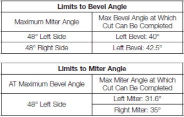
Miter Control (Fig. 5)
The miter lock knob (E) and miter latch button (F) allow you to miter your saw to 48° right and 48° left. The miter latch will automatically locate at 10". 15", 22.S'. 31.62" and 45“ both left and right. To miter the saw. unlock the miter lock mechanism by puling up on the miter lock knob (E). Push the miter latch button (F) down, and set the miter angle desired on the miter scale (H). Lock the miter lock knob by pushing it down.
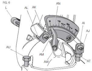
Bevel Lock Knob (Fig. 3, 6)
The bevel lock allows you to bevel the saw 48° to the left. To adjust the bevel setting, turn the bevel lock knob (L) counterdockwise to loosen. To tighten, turn the bevel lock knob dockwise.
CAUTION: Pinch hazard. Be sure to tighten bevel lock knob before aefusting overrides.
Bevel Stop Override (Fig. 6)
The bevel stop override allows you to bevel the saw up to 3° to the right Loosen the 0° bevel stop override screw (Al) until the 0° bevel stop override bracket (AJ) can freely rotate. Turn the 0° bevel stop override bracket to allow the saw to rotate past the zero bevel position, then retighten the override screw. FIG. 6 yyg
45° Bevel Stop Override (Fig. 6)
The bevel stop override allows you to bevel the saw up to 48° to the left Loosen the 45° bevel stop override screw (AK) until the 45° stop override bracket (AL) can freely rotate. Tun the 45° bevel stop override bracket (AL) to allow the saw to rotate past the 45° bevel position, then retighten the override screw.
Rail Lock Knob (Fig. 3)
The rail lock knob (T) allows you to lock the saw head firmly to keep it from sliding on the rails. This is necessary when making certain cuts or when transporting the saw.
Lock Down Pin (Fig. 3)
WARNING: The lock down pin should be used ONLY when carrying or storing the saw. NEVER use the lock down pin for any cutting operation.
To lock the saw head in the down position, push the saw head down, push the lock down pin (W) in and release the saw head. This will hold the saw head safely down for moving the saw from place to place. To release, press the saw head down and pull the pin out.
OPERATION
WARNING: To reduce the risk of serious personal injury, turn tool off and remove the battery pack before transporting, making any adjustments or removing /installing attachments or accessories. .An accidental start-up can cause Injury.
WARNING: Always use eye protection. All users and bystanders must wear eye protection that conforms to ANSI Z87.11CAN/CSA Z94.3).
WARNING: To ensure the blade path is clear of obstructions, aiways make a dry run of the cut without power before making any cuts on the workpiece.
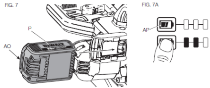
Installing and Removing the Battery Pack (Fig. 7)
NOTE: For best results, make sure your battery pack is fully charged.
To install the battery pack (P) into the tool handle, align the battery pack with the rails inside the tool's handle and slide it into the handle until the battery pack is firmly seated in the tool and ensure that it does not disengage.
To remove the battery pack tfom the tod, press the release button (AO) and firmly pull the battery pack out of the tool handle. Insert it into the charger as described in the charger section of this manual.
FUEL GAUGE BATTERY PACKS (FIG. 7A)
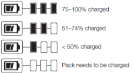
Some DEWALT battery packs include a fuel gauge which consists of three green LED lights that indicate the level of charge remaining in the battery pack.
The fuel gauge is an indication of approximate levels of charge remaining in the battery pack according to the fdlowing indicators:
To actuate the fuel gauge, press and hold the fuel gauge button (AP). A combination of the three green LED lights will illuminate designating the level of charge left. When the level of charge in the battery is below the usable limit, the fuel gauge will not illuminate and the battery will need to be recharged.
NOTE: The fuel gauge is only an indication of the charge left on the battery pack. It does not indicate tod functionality and is subject to variation based on product components, temperature and end-user application.
For more information regarding fuel gauge battery packs, please call 1-800-4-DEWALT (1 -800-433-9258) .
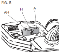
Trigger Switch (Fig. 8)
To turn the saw on, push the lock-off lever (Ft) to the left, then depress the trigger switch (A). The saw will run while the switch is depressed. Allow the blade to spin up to full operating speed before making the cut To turn the saw off, release the switch. Allow the blade to stop before raising the saw head. There is no provision tor locking the switch on. A hole (AR) is provided in the trigger for insertion of a padlock to lock the switch off.
Your saw is not equipped with an automatic electric blade brake, but the saw blade should stop within 5 seconds of trigger release. This is not adjustable. If the stop time repeatedly exceeds 5 seconds, have the tool serviced by an authorized DEWALT service center.
Always be sure the blade has stopped before removing it from the kerf.
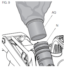
Dust Extraction (Fig. 3, 9)
WARNING: To reduce the risk of serious personal Injury, turn tool off and remove the battery pack before transporting, making any adjustments or removing/installing attachments or accessories. An accidental start-up can cause injury.
Your saw has a built-in dust port (N) that allows either the supplied dust bag (AQ) or a shop vacuum system to be connected.
TO ATTACH THE DUST BAG
Fit the dust bag (AQ) to the dust port (N) as shown in Figure 9.
TO EMPTY THE DUST BAG
Remove dust bag (AQ) from the saw and gently shake or tap the dust bag to empty.
Reattach the dust bag back onto the dust port (N).
You may notice that all the dust wil not come free from the bag. This will not affect cutting performance but will reduce the saw's dust collection efficiency. To restore your saw's dust collection efficiency, depress the spring inside the dust bag when you are emptying it and tap it on the side of the trash can or dust receptacle.
CAUTION: Never operate this saw unless the dust bag or DEWALT dust extractor is in place. Wood dust may create a breathing hazard
Cutting With Your Saw (Fig. 3)
If the slide feature is not used, ensure the saw head is pushed back as far as possible and the rail lock knob (T) is tightened. This will prevent the saw from sliding along its ra'ls as the workpiece is engaged.
NOTE: DO NOT CUT METALS OR MASONRY WITH THIS SAW. Do not use any abrasive blades.
NOTE: Refer to Guard Actuation and Visibility in the Adjustments section for important information about the lower guard before cutting.
CROSSCUTS (FIG. 3,10)
A crosscut is made by cutting wood across the grain at any angle. A straight crosscut is made with the miter arm at the zero degree position. Set and lock the miter arm at zero, hold the wood firmly on the table and against the fence. With the rail lock knob (T) tightened, turn on the saw by squeezing the trigger switch (A) shown in Figure 3.
When the saw comes up to speed (about 1 second) lower the arm smoothly and slowly to cut through the wood. Let the blade oome to a full stop before raising arm.
When cutting anything larger than a 2 x 4 (51 x 102), use an out-down-back motion with the rail lock knob (T) loosened. FfJI the saw out, toward you, lower the saw head down toward the workpiece, and slowly push the saw back to oomptete the cut. Do not allow the saw blade to contact the top of the workpiece while pulling out The saw may run toward you. possibly causing personal injury or darnage to the workpiece.
WARNING: Atways use a work clamp to maintain control and reduce the risk of workpiece damage and personal iryury, if your hands are required to be within 6" (152 mm) of the blade during the cut.
NOTE: The rail lock knob (T) shown in Figure 3 must be loose to allow the saw to slide along its rails.
Miter crosscuts are made with the miter aim at some angle other than zero. This angle is often 46° for making comers, but can be set anywhere from zero to 48? left or 48° right. Make the cut as described above.
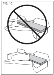
When performing a miter cut on workpieces wider than a 2 x 6 that are shorter in length, always place the longer side against the fence (Fig. 10).
To cut through an existing pend Sne on a piece of wood, match the angle as close as possible. Cut the wood a little too long and measue from the pencil line to the cut edge to determine which direction to adjust the miter angle and recut. This wil take some practice, but it is a commonly used technique.
BEVEL CUTS (FIG. 3)
A bevel cut is a crosscut made with the saw blade leaning at an angle to the wood. In order to set the bevel, loosen the bevel lock knob (L), and move the saw to the left as desired. Once the desired bevel angle has been set. tighten the bevel lock firmly.
Refer to the Features and Controls section for detailed instructions on the bevel system.
Bevel angles can be set from 3° right to 48? left.
QUALITY OF CUT
The smoothness of any cut depends on a number of variables. Things like material being cut, blade type, blade sharpness and rate of cut all contribute to the quality of the cut.
When smoothest cuts are desired for mokfrng and other precision work, a sharp (60 tooth carbide Up) blade and a slower, even cutting rate will produce the desired results.
Ensure that the material does not move or creep while cutting; clamp it securely in place. Atways let the blade come to a full stop before raising arm.
If smal fibers of wood still spit out at the rear of the workpiece, stick a piece of masking tape on the wood where the cut will be made. Saw through the tape and carefully remove tape when finished.
For varied cutting applications, refer to the list of recommended saw blades for your saw and select the one that best fits your needs. FiefertoSaw Blades under Optional Accessories
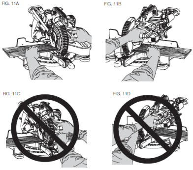
BODY AND HAND POSITION (FIG. 11A-11D)
Proper positioning of your body and hands when operating the miter saw will make cutting easier, more accurate and safer. Never place hands near cutting area. Place hands no closer than 6" (152 mm) from the blade. Hold the workpiece tightly to the table and the fenoe when cutting. Keep hands in position until the trigger has been released and the blade has completely Stopped. ALWAYS MAKE DRY RUNS (UNPOWERED) BEFORE RNISH CUTS SO THAT YOU CAN CHECK THE PATH OF THE BLADE. DO NOT CROSS HANDS, AS SHOWN IN FIGURE 11C.
Keep both feet firmly on the floor and maintain proper balance. As you move the miter arm left and right, folow it and stand slightly to the side of the saw blade. Sight through the guard louvers when following a pencil line.
CLAMPING THE WORKPIECE
WARNING: To reduce the risk of serious personal injury, turn tool off and remove the battery pack before transporting, making any adjustments or removing/installing attachments or accessories. An accidental start-up can cause injury.
WARNING: A workpiece that is clamped, balanced and secure before a cut may become unbalanced after a cut is completed. An unbalanced toad may tip the saw or anything the saw is attached to, such as a table or workbench. When making a cut that may become unbalanced, property support the workpiece and ensure the saw is firmly bolted to a stable surface. Personal injury may occur.
WARNING: The damp foot must remain damped above the base of the saw whenever the clamp is used. Always damp the workpiece to the base of the saw -not to any other part of the work area. Ensure the damp foot is not damped on the edge of the base of the saw.
WARNING: Always use a work clamp to maintain control and reduce the risk of workpiece damage and personal injury, if your hands are required to be within 6‘ (152 mm) of the blade during the cut.
If you cannot secure the workpiece on the table and against the fence by hand (irregular shape, etc.), or your hand would be less than 6" (152 mm) from the blade, a clamp or other fixture must be used.
Use the material clamp provided with your saw. To purchase a material clamp, contact your local retailer or DEWALT service center.
Other aids such as spring clamps, bar clamps or C-clamps may be appropriate for certain sizes and shapes of material. Use care in selecting and placing these clamps. Take time to make a dry run before making the cuL
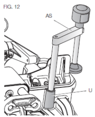
TO INSTALL CLAMP (FIG. 3,12)
Insert the clamp (AS) into the hole (U) behind the fence. The clamp shodd be facing toward the back of the miter saw. The groove on the damp rod should be fully inserted into the base. Ensure this groove is filly inserted Into the base of the miter saw. If the groove is visible, the clamp wll not be secure.
Rotate the clamp 180° toward the front of the miter saw.
Loosen the knob to adjust the clamp up or down, then use the fine adjust knob to firmly clamp the workpiece.
NOTE: Place the clamp on the opposite side of the base when beveling. ALWAYS MAKE DRY RUNS (UNPOWERED) BEFORE RNISH CUTS TO CHECK THE PATH OF THE BLADE ENSURE THE CLAMP DOES NOT INTERFERE WITH THE ACTION OF THE SAW OR GUARDS.
ADJUSTMENTS
WARNING: To reduce the risk of serious personal injury, turn tool off and remove the battery pack before transporting, making any adjustments or removing/instaUing attachments or accessories. An accidental start-up can cause injury.
Your miter saw is fully and accurately adjusted at the factory at the time of manufacture. If readjustment due to shipping and handling or any other reason is required, follow the instructions below to adjust your saw.
Once made, these adjustments shoild remain accurate. Take a little time now to follow these directions carelully to maintain the accuracy of which your saw is capable.
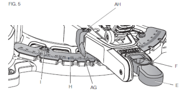
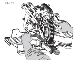
Miter Scale Adjustment (Fig. 5, 13)
Lock the arm in the down position. Unlock the miter lock knob <E) and swing the miter arm until the miter latch button (F) locks it at the 0° miter position. Do not lock the miter lock knob. Race a square against the saw's fence and blade, as shown. (Do not touch the tips of the blade teeth with the square. To do so will cause an inaccurate measurement.) If the saw blade is not exactly perpencfcular to the fence, loosen the three screws (I) that hold the miter scale (H) and move the miter lock handle and the scale left or right until the blade Is perpendicular to the fence, as measured with the square. Retighten the three screws. Pay no attention to the reading of the miter pointer at this time.
Miter Pointer Adjustment (Fig. 5)
Unlock the miter lock mechanism by pulling up on the miter lock knob (E). Push the miter latch button (F) down and allow the miter latch to snap into place as you rotate the miter arm to zero. Observe the miter pointer (AG) and miter scale <H) shown in Figure 5. If the pointer does not indicate exactly zero, loosen the miter pointer screw (AH) holding the pointer in place, reposition the pointer and tighten the screw.
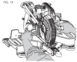
Bevel Square to Table Adjustment (Fig. 3, 6, 14)
To align the blade square to the table, lock the arm In the down position with the lock down pin (W). Place a square against the blade, ensuring the square is not on top of a tooth. Loosen the bevel lock knob (L) and ensure the arm is firmly against the 0° barel stop. Rotate the 0° bevel adjustment screw (AT) with the 1/2" (12.7 mm) socket (not provided) as necessary so that the blade is at 0° bevel to the table, as measured with the square.
Bevel Pointer (Fig. 6)
If the bevel pointer (AM) does not indicate zero, loosen the screw that holds the bevel pointer (AW) in place and move it as necessary. Ensure the 0° bevel is correct and the bevel pointer is set before adjusting any other bevel angle screws.
Bevel Stop 45° Left Adjustment (Fig. 3, 6)
To adjust the left 45° bevel stop, first loosen the bevel lock knob and tilt the head to the left. It the bevel pointer does not indicate exactly 46°. turn the left 45° bevel adjustment screw (AU) until the bevel pointer reads 45°.
Guard Actuation and Visibility (Fig. 3, 23)
CAUTION: Pinch hazard. To reduce the risk of injury, keep thumb underneath the operating handle when pulling the handle down. The lower guard will move up as the operating handle Is pulled dawn, which could cause pinching.
The tower guard (D) on your saw has been designed to automatically uncover the blade when the arm is brought down and to cover the blade when the arm is raised.
Before each use or after making adjustments, cycle the arm (unpowered) and make sure the guard opens smoothly and closes fully. It should not contact the blade. With the arm up, raise the guard (unpowered) as shown in Figue 23 and release. The guard should fully close rapidly. Do not operate the saw if the guard does not move freely and fully dose rapidly. Never clamp or tie the guard in an open position when operating the saw.
The guard can be raised by hand when installing or removing saw blades or for inspection Of the saw. NEVER RAISE THE LOWER GUARD MANUALLY UNLESS THE BLADE IS STOPPED.
NOTE: Certain special cuts of large material will reqiire that you manualy raise the guard. Refer to Cutting Large Material under Special Cuts
The front section of the guard is louvered for visibility while cutting. Although the louvers dramatically reduce flying debris, they are openings in the guard and safety glasses should be worn at all times.
Rail Guide Adjustment (Fig. 3)
Periodically check the rails (M) for any play or clearance. The rails can be cleaned with a dry dean doth. The right rail can be adjusted with the set screw (S) shown in Figure 3. To reduce clearance, use a 4 mm hex wrench and rotate the set screw dockwise gradually while sliding the saw head back and forth. Reduce play while maintaining minimum slide force.
Support for Long Pieces
WARNING: To reduce the risk of serious personal injury, turn tool off and remove the battery pack before transporting, making any adjustments or removing/installing attachments or accessories. An accidental start-up can cause iryury.
ALWAYS SUPPORT LONG PIECES.
Never use another person as a substitute for a table extension, as additional supjoort for a workpiece that is longer or wider than the basic miter saw table or to help feed, support or pull the workpiece.
Support long workpieces using any convenient means such as sawhorses or similar devices to keep the ends from dropping.
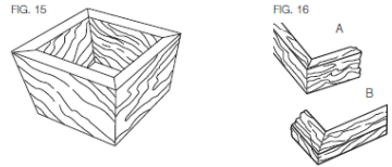
Cutting Picture Frames, Shadow Boxes And Other FourSided Projects (Fig. 15, 16)
To best understand how to make the items listed here, we suggest that you try a few simple projects using scrap wood until you develop a “feel" for your saw.
Your saw is the perfect tool for mitering comers like the one shown in Figure 15. Sketch A in Rgure 16 shows a joint made by using the bevel adjustment to bevel the edges of the two boards at 45° each to produce a 90s comer. For this joint the miter arm was locked in the zero position and the bevel adjustment was locked at 45°. The wood was positioned with the broad flat side against the table and the narrow edge against the fence. The cut could also be made by mitering right and left with ihe broad surface against the fence.
Cutting Trim Molding and Other Frames (Fig. 16)
Sketch B in Rgure 16 shows a joint made by setting the miter arm at 45° to miter the two boards to form a 90“ oomer. To make this type of joint, set the bevel acjustment to zero and the miter arm to 45°. Onoe again, position the wood with the broad flat side on the table and the narrow edge against the fence.
Figures 15 and 16 am for four-sided objects only.
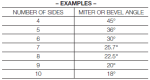
As the number of sides changes, so do the miter and bevel angles. The chart below gives the proper angles for a variety of shapes.
The chart assumes that all sides are of equal length. For a shape that is not shown in the chart use the following formula: 180“ divided by the number of sides equals the miter (if the material is cut vertically) or bevel angle (if the material is cut laying flat).
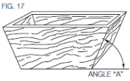
Cutting Compound Miters (Fig. 17)
A compound miter is a cut made using a miter angle and a bevel angle at the same time. This is the type of cut used to make frames or boxes with slanting sides like the one shown in Rgure 17.
NOTE: If the cutting angle varies from cut to cut, check that the bevel lock knob and the miter lock handle are securely locked. These must be locked after making any changes in bevel or miter.
The chart at the end of this manual (Table 1) will assist you in selecting the proper bevel and miter settings for common compound miter cuts. To use the chart, select the desired angle A (Fig. 17) of your project and locate that angle on the appropriate arc in the chart. From that point follow the chart straight down to find the correct bevel angle and straight across to find the correct miter angle.
Set your saw to the prescribed angles and make a few trial cuts. Practice fitting the cut pieces together until you develop a feel for this procedure and feel comfortable with it Example: To make a 4-sided box with 26“ exterior angles (Angle A, Rg. 17), use the upper right arc. Find 26° on the arc scale. Follow the horizontal intersecting line to either side to get miter angle setting on saw (42°). Likewise, follow the vertical intersecting line to the top or bottom to get the bevel angle setting on the saw (18°). Always try cuts on a few scrap pieces of wood to verify ihe settings on the saw.
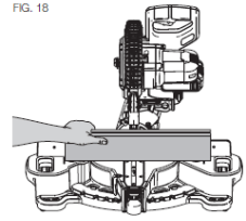
Cutting Base Molding (Fig. 18)
Straight 90“ cuts:
Position ihe wood against the fence and hold it in place as shown in Rgure 18. Turn on the saw, allow the blade to reach lull speed and lower the arm smoothly through the cut.
CUTTING BASE MOLDING UP TO 3.5” (89 mm) HIGH VERTICALLY AGAINST THE FENCE
Position material as shown in Rgure 18.
All cuts should be made with the back of the molding against the fence and with the bottom of the molding against the table.
Material up to 3.5” (89 mm) can be cut as described above.
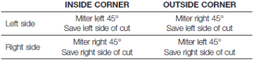
CUTTING CROWN MOLDING
In order to fit property, crown molding must be compound mitered with extreme accuracy. The two flat surfaces on a given piece of crown molding are at angles that, when added together, equal exactly 90°. Most, but not all, crown molding has a top rear angle (the section that fits flat against the ceiling) of 52° and a bottom rear angle (the part that fits flat against the wall) of 38°.
Your miter saw has special pre-set miter detent points at 31.6“ left and right for cutting crown molding at the proper angle. There is also a mark on the bevel scale at 33.8“.
The Bevel Setting/Type of Cut chart gives the proper settings for cutting crown molding. (The numbers for the miter and bevel settings are very precise and are not easy to accurately set on your saw.) Since most rooms do not have angles of precisely 90°, you will have to fine tune your settings anyway.
MAINTENANCE
WARNING: To reduce the risk of serious personal injury, turn tool off and remove the battery pack before transporting, making any adjustments or removing I installing attachments or accessories. An accidental start-up can cause injury.
WARNING: To reduce the risk of serious personal injury, DO NOT touch the sharp points on the blade with fingers or hands while performing any maintenance.
DO NOT use lubricants or cleaners (partialarty spray or aerosol) In trie vidnfty of tbe plastic guard. The polycarbonate material used in the guard is subject to attack by certain chemicals.
All bearings are sealed. They are lubricated for life and need no further maintenance.
Periodically clean all dust and wood chips from around AND UNDER the base and the rotary table. Even though slots are provided to allow debris to pass through, some dust wil accumulate.
The brushes are designed to give you several years of use. If they ever need replacement, return the tool to the nearest service center for repair.
Cleaning
WARNING: Blow dirt and dust out of aH air vents and guard mechanisms inapplicable) with clean, dry air at least once a week. To minimize the risk of eye injury, always wear ANSI Z87.1 approved eye protection when performing this.
WARNING: Never use solvents or other harsh chemicals tor cleaning the non-metallic parts of the tool. These chemicals may weaken the plastic materials used in these parts. Use a doth dampened only with wafer and mid soap. Never let any liquid get inside the tool: never immerse any part of the tool into a liquid.
CHARGER CLEANING INSTRUCTIONS
WARNING: Shock hazard. Disconnect the charger from the AC outlet before cleaning. Dirt and grease may be removed from the exterior of the charger using a doth or soft non-metallic blush. Do not use water or any cleaning solutions.
DUST DUCT CLEANING
Depending on your cutting environment saw dust can dog the dust duct and may prevent dust from flowing away from the cutting area properly. With the battery pack removed and the saw head raised fully, low pressure air or a large diameter dowel rod can be used to dear the dust out of the dust duct.
Accessories
WARNING: Since accessories, other than those offered by DEWALT, have not been tested with this product, use of such accessories with this tool could be hazardous. To reduce the risk of injury, only DEWALT recommended accessories should be used with this product. Recommended accessories for use with you tod are available at extra cost from your local dealer or authorized service center. If you need assistance in locating any accessory, please contact DEWALT Industrial Tod Co., 701 East Joppa Road, Towson, MD 21286, cal 1 -800-4-DEWALT (1 -800-433-9258) or visit our website: www.dewalt.oom.
Repairs
To assure product SAFETY and RELIABILITY, repairs, maintenance and adjustment (induding brush inspection and replacement) should be performed by a DEWALT factory service center, a DEWALT authorized service center or other gualilied service personnel. Always use identical replacement parts.
Register Online
Thank you for your purchase. Register you product now for:
WARRANTY SERVICE: Registering your product will help you obtain more efficient warranty service in case there is a problem with you product.
CONFIRMATION OF OWNERSHIP: In case of an insuance loss, such as fire, flood or theft, you registration of ownership will serve as you proof of purchase.
FOR YOUR SAFETY: Registering you product wil allow us to contact you in the unlikely event a safety notification is required under the Federal Consumer Safety Act.
Troubleshooting Guide
BE SURE TO FOLLOW SAFETY RULES AND INSTRUCTIONS
TROUBLE!
WHAT'S WRONG?
WHAT TO DO
Saw will not start
1. Battery not installed
1. Install battery. Refer to Installing and Removing Battery Pack.
2. Battery not charged
2. Charge battery. Refer to Charging Procedure
3. Brushes worn out
3. Have brushes replaced by authorized service center.
Saw makes unsatisfactory cuts
1. Dull blade
1. Replace blade. Refer to Changing or Installing a New Saw Blade.
2. Blade mounted backwards
2. Turn blade around. Refer to Changing or Installing a New Saw Blade.
3. Gum or pitch on blade
3. Remove blade and clean with coarse steel wool and turpentine or household oven cleaner.
4. Incorrect blade for work being done
4. Change the blade type. Refer to Saw Blades under Optional Accessories.
XPS™ worklight is flashing
Machine vibrates excessively
1. Battery not charged
1. Charge battery. Refer to Charging Procedure
1. Saw not mounted securely to stand or work bench
1. Tighten all mounting hardware. Refer to Bench Mounting.
2. Stand or bench on uneven floor
2. Reposition on flat level surface. Refer to Familiarization.
3. Damaged saw blade
3. Replace blade. Refer to Changing or Installing a New Saw Blade.
Does not make accurate miter cuts
1. Miter scale not adjusted correctly
1. Check and adjust. Refer to Miter Scale Adjustment under Adjustments.
2. Blade is not square to fence
2. Check and adjust. Refer to Miter Scale Adjustment under Adjustments.
3. Blade is not perpendicular to table
3. Check and adjust fence. Refer to Bevel Square to Table Adjustment under Adjustments.
4. Wori<piece moving
4. Clamp worfcpiece securely to fence or glue 120 grit sandpaper to fence with rubber cement.