Loading ...
Loading ...
3
• The wall opening must be the correct size. See
Figure 1 for wall sleeve dimensions and Figure 3 for
minimum wall opening size.
• The wall sleeve needs to be installed with minimum
clearances to the floor and adjacent walls. Minimum
projections of the sleeve into and out of the room
will also have to be met. See Figures 2 and 4 as
well as Table 1 for details.
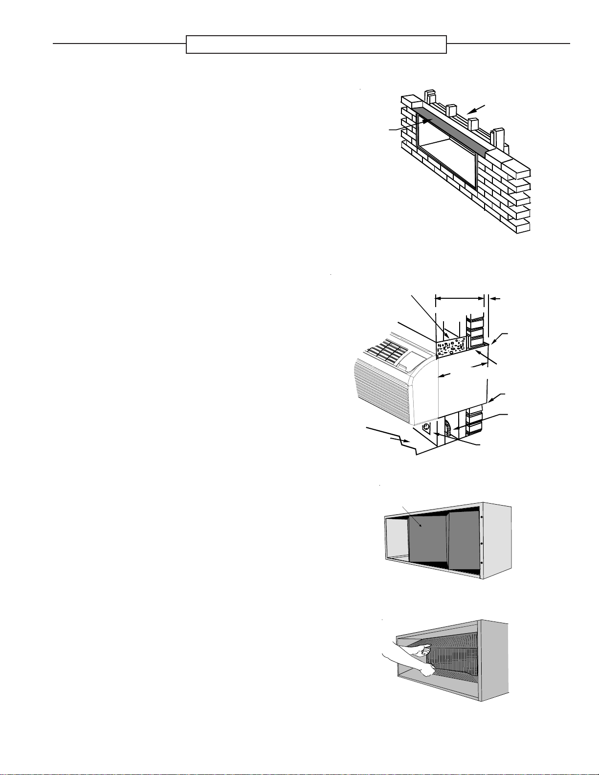
• If installed in a concrete or masonry wall, a lintel
must be provided in the wall opening for support. Do
not use the wall sleeve as a lintel. See Figure 5
for a typical lintel construction.
• When installed in the opening, the wall sleeve must
be horizontally level from side to side and pitched
(one quarter bubble in the sight glass) to the
outside. DO NOT SLOPE THE WALL SLEEVE
TOWARD THE ROOM.
• The installer must determine and supply the
mounting bolts and/or screws to attach the wall
sleeve to the sides of the wall opening. Make sure
the wall opening is adequate for strong support.
• The installer must provide adequate sealing and
insulation around the sleeve after it is installed. See
Figure 6 for one of many types of constructions.
• If used, a 208/230-volt wall receptacle must be
located within 58 inches of the lower right sleeve
corner. Extension cords must not be used with the
unit. See the note on Figure 1.
Note: Additional extension kits are not allowed beyond
the 24” wall sleeve depth.
OUTDOOR E NCLOSURE P ANEL R EMOVAL
The sleeve stiffener must be taken out before the
enclosure panel can be removed from the sleeve.
1. Remove the zig-zag folded cardboard sleeve stiff-
ener (Figure 7).
2. Grasping the top and bottom flanges of the rear clo-
sure panel as shown in Figure 8, pull the entire panel
out diagonally from one side.
Install the wall sleeve condenser air grille by using the
screws and holes provided. (See the Installation In-
structions provided for the grille kits.)
WOOD
FRAME
LINTEL
Figure 5 - Framing with Lintel
STEEL
LINTEL
CAULK TOP,
BOTTOM, AND
BOTH SIDES
1/4"
6 mm
MINIMUM
PROJECTION
CONCRETE
LINTEL
POWER SUPPLY
CONDUIT
RECEPTACLE
FINISHED
FLOOR
13 1/2" (340 mm)
MAXIMUM
(NO ACCESSORIES)
16" - 24"
406mm - 610 mm
CAULK TOP,
BOTTOM, AND
BOTH SIDES
Figure 6 - Block and Brick Veneer Installation
Sleeve
Stiffener
Figure 7- Sleeve Stiffener Removal
Figure 8 - Panel Removal
PRE-INSTALLATION CONSIDERATIONS
Before proceeding with the sleeve installation, ensure the following guidelines for locating the wall opening and sleeve are
met.
Loading ...