Loading ...
Loading ...
Loading ...
Seagate FireCuda Product Manual, Rev. H 22
Configuring and Mounting
3.3 Drive Grounding
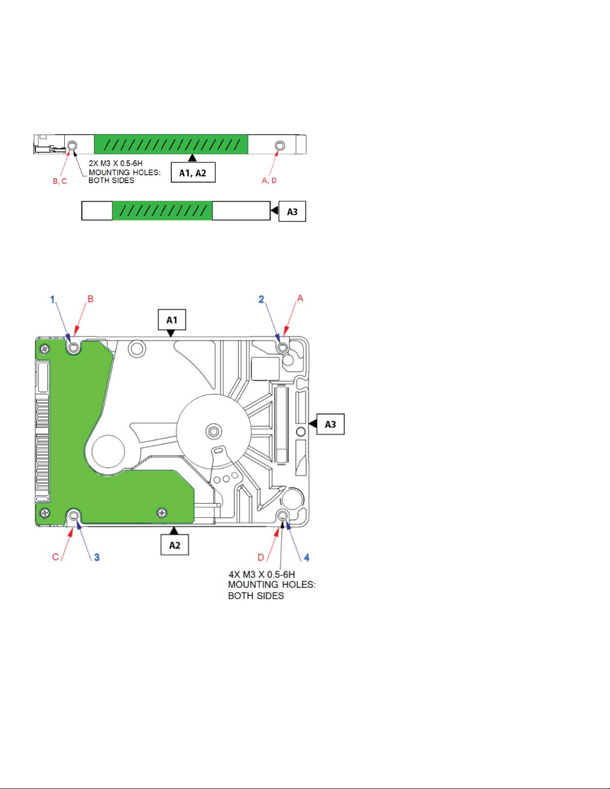
Care should be taken when mounting the drive in a system chassis. The drive should be mounted using four screws in the side
mounting holes (positions A, B, C, and D as in
Figure 4 and Figure 5) or bottom mounting holes (positions 1, 2, 3, and 4 as in Figure
5
) grounded to the system chassis. At least one mounting screw is required for proper grounding. See Figure 4 for drive grounding
using four screws in the side mounting holes and
Figure 5 for drive grounding using four screws in the bottom mounting holes. The
sidewall surfaces A1, A2, A3 (cross-hatched green shaded areas as in
Figure 4) and the green highlighted area (as labeled in Figure 5)
should not be used for system grounding purposes.
Figure 4 Drive Grounding Side Mounting for 1-disk and 2-disk models)
The green highlighted area (PCBA as in Figure 5) should never make contact with the system chassis to prevent electrical shorting of
the drive. Contact must be limited to side mounting holes (positions A, B, C, and D as in
Figure 4 and Figure 5) or bottom mounting
holes (positions 1, 2, 3, and 4 as in
Figure 5).
Figure 5 Drive Grounding Bottom Mounting for 1-disk and 2-disk models
Notes:
• Side Mounting - Use four metal screws in positions A, B, C, and D.
• Bottom Mounting - Use four metal screws in positions 1, 2, 3, and 4.
• Do NOT use sides A1, A2 or A3 for grounding purposes.
• If less than four screws are used, at least one mounting screw is required for proper grounding.
Loading ...
Loading ...
Loading ...