ProSafe 24 Port Gigabit Switch
Installation Guide
Full_IG.book Page 1 Monday, January 9, 2012 6:11 PM

2
© 2011 NETGEAR, Inc. All rights reserved.
No part of this publication may be reproduced, transmitted, transcribed,
stored in a retrieval system, or translated into any language in any form or by
any means without the written permission of NETGEAR, Inc.
Technical Support
Thank you for choosing NETGEAR. To register your product, get the latest
product updates, or get support online, visit us at http://support.netgear.com.
Phone (US only): 1-888-NETGEAR
Phone (Other Countries):
Check the list of phone numbers at:
http://support.netgear.com/app/answers/detail/a_id/984
Trademarks
NETGEAR, the NETGEAR logo, ReadyNAS, ProSafe, Smart Wizard, Auto
NETGEAR, the NETGEAR logo, and Connect with Innovation are trademarks
and/or registered trademarks of NETGEAR, Inc. and/or its subsidiaries in the
United States and/or other countries. Information is subject to change without
notice. Other brand and product names are registered trademarks or
trademarks of their respective holders. © 2011 NETGEAR, Inc. All rights
reserved.
Statement of Conditions
In the interest of improving internal design, operational function, and/or
reliability, NETGEAR reserves the right to make changes to the products
described in this document without notice. NETGEAR does not assume any
liability that may occur due to the use or application of the product(s) or circuit
layout(s) described herein.
Full_IG.book Page 2 Monday, January 9, 2012 6:11 PM
3
Package Contents
Verify that all items are in the box. The package includes:
• ProSafe 24-port Gigabit Switch with 2 Gigabit SFP Combo Ports
JGS524F V1
• Power cord with localized plug
• Adhesive feet
• Rack-mount brackets and hardware
• Installation Guide (this document)
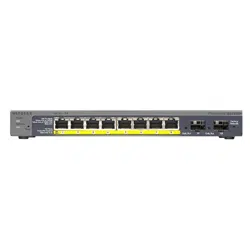
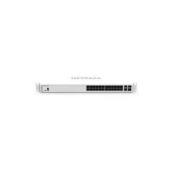
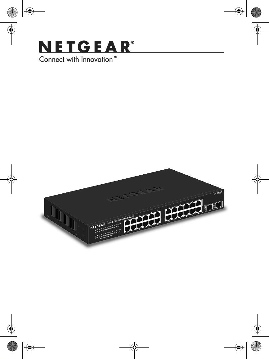
Front View
24 Gigabit ports
LEDs
Gigabit SPF
combo ports
The switch supports 10 Mbps, 100 Mbps, and 1000 Mbps
connections. Using Gigabit Ethernet (1000 Mbps), the switch sends
files across the network at speeds up of to 2000 Mbps due to the full-
duplex nature of Gigabit Ethernet connections. You can either
connect 24 Ethernet copper cables or 22 copper cables with 2 optical
fibers.
The switch supports straight-through or crossover Ethernet cables on
24 ports. Each of these ports configures itself based on the cable that
you plug into it. You can use the switch to connect Ethernet devices
such as computers, file servers, printers, routers, switches, or hubs.
Full_IG.book Page 3 Monday, January 9, 2012 6:11 PM
4
Select a Location
Decide where you want to place the switch. Find a flat horizontal
surface or a 19-inch rack.
Make sure that the location is:
• Not in direct sunlight or near a heater or heating vent.
• Not cluttered or crowded. There should be at least 2 inches (5
cm) of clear space on all sides of the switch.
• Well ventilated, especially if it is in a closet.
Install the Switch
1. For each device that you want to connect to the switch, provide
an enhanced Category 5 (Cat 5e) Ethernet cable with RJ-45
connections. Each Ethernet cable has to be less than 328 feet
(100 meters) long.
2. Install the switch on a flat surface or in a standard 19-inch rack.
• Flat surface. The switch comes with four self-adhesive
footpads. Stick one footpad on each of the four concave
spaces on the bottom of the switch. The footpads cushion the
switch against shock and vibrations.
• Rack mounting. Follow the instructions in the 19-Inch Rack
Mounting section.
Verify Cable Connections
Before you apply power, perform the following checks:
1. Inspect the equipment thoroughly.
2. Verify that all cables are installed correctly.
3. Check cable routing to ensure that cables are not damaged and will
not create a safety hazard.
4. Be sure that all equipment is mounted securely.
Full_IG.book Page 4 Monday, January 9, 2012 6:11 PM
5
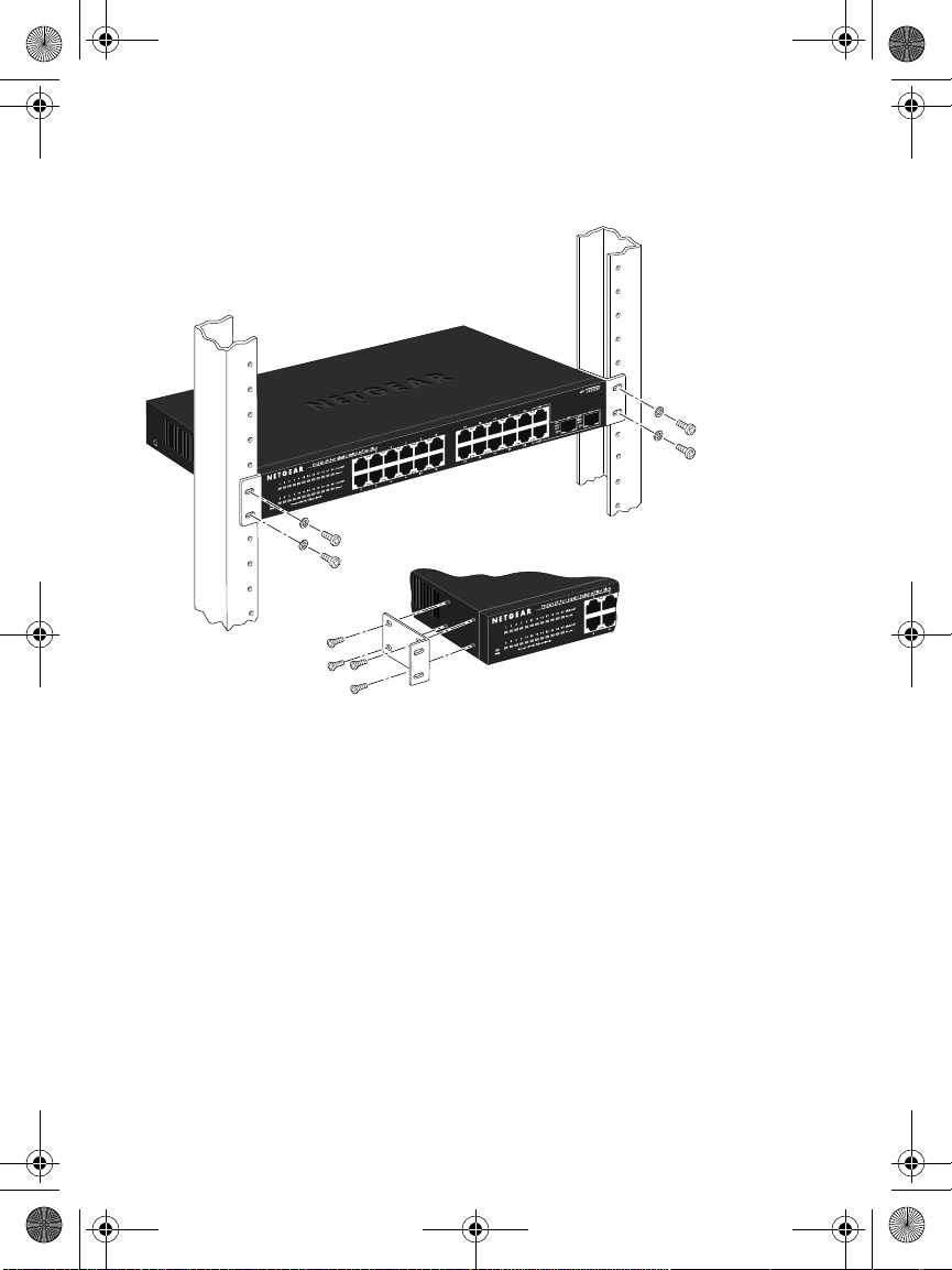
19-Inch Rack Mounting
Use the rack-mount kit supplied with your switch.
1. Use the Phillips head screws to fasten the mounting brackets to
the sides of the switch. Tighten the screws with a No. 1 Phillips
screwdriver.
2. Align the bracket and rack holes. Use two pan-head screws with
nylon washers to fasten each bracket to the rack. Tighten the
screws with a No. 2 Phillips screwdriver to secure the switch in the
rack.
Full_IG.book Page 5 Monday, January 9, 2012 6:11 PM
6
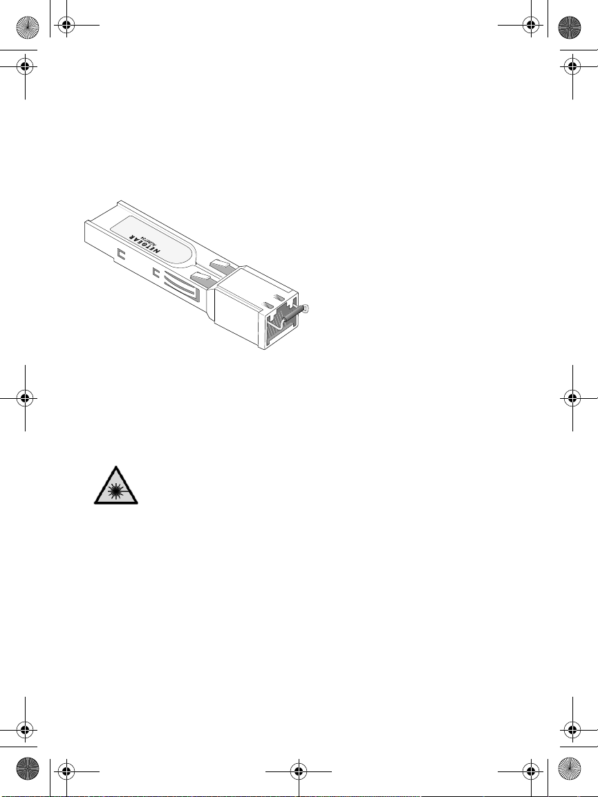
Optical Modules (Sold Separately)
You can use compatible optical modules such as the NETGEAR
ProSafe GBIC SFP Modules AGM731F and AGM732F with your
switch. These modules provide full-duplex 1000 Mbps Ethernet
operation in each direction for NETGEAR switches.
AGM731F or AGM732F
The switch automatically detects the module, so you can simply plug
it into an available module slot. Plugging in an SFP module disables
the associated RJ-45 port. The modules can be inserted or removed
while the switch is operational.
Class 1 laser product.
Class 1 LED product.
Because invisible laser radiation may be emitted from the
aperture of the port when no fiber cable is connected, avoid
exposure to laser radiation, and do not stare into open
apertures.
.
Full_IG.book Page 6 Monday, January 9, 2012 6:11 PM
7
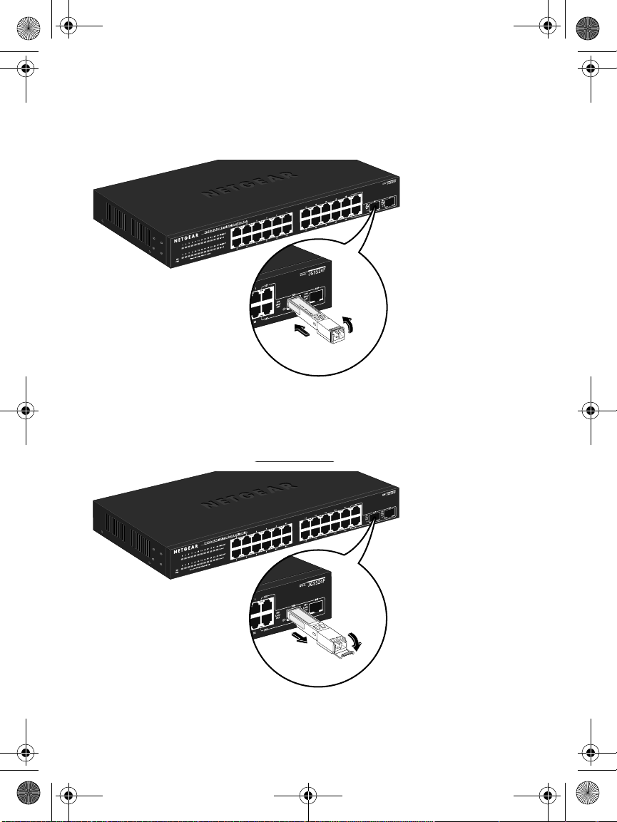
Install an Optical Module
Insert the module firmly into the slot that supports the SFP interface.
You should hear a click when the module is firmly seated.
Tx
Rx
Remove an Optical Module
Release the module latch by pulling down the handle bar across the
module, and pull the module out of the module slot.
Full_IG.book Page 7 Monday, January 9, 2012 6:11 PM

8
Troubleshooting
You can use the LEDs to troubleshoot hardware problems.
Power LED Is Off
The switch has no power.
• Make sure that the power cord is securely connected to the
switch.
• Make sure that the power cord is connected to a functioning
power outlet. If it is connected to a power strip, make sure that
the power strip is turned on. If the socket is controlled by a light
switch, make sure the switch is in the on position.
Port LEDs
If a port LED is off for a connected device or the LED stays on
continuousl,y there is a hardware connection problem.
• Make sure that the cable connectors are securely plugged in to
the switch and the device.
• Make sure that the connected device is turned on.
• If the Ethernet cable is connected to a network interface card or
other Ethernet adapter, make sure that the card or adapter is
installed correctly and is working.
• Make sure that the cable is less than 328 feet (100 meters) long.
Full_IG.book Page 8 Monday, January 9, 2012 6:11 PM
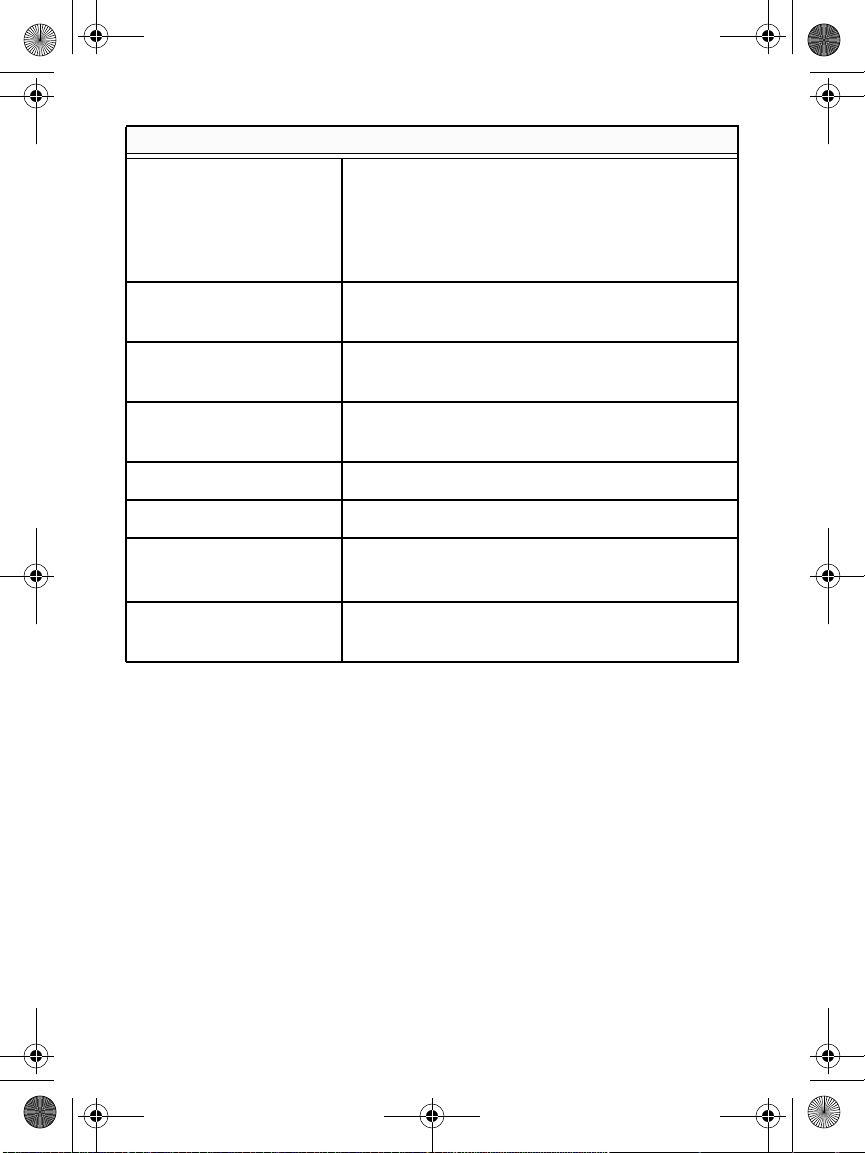
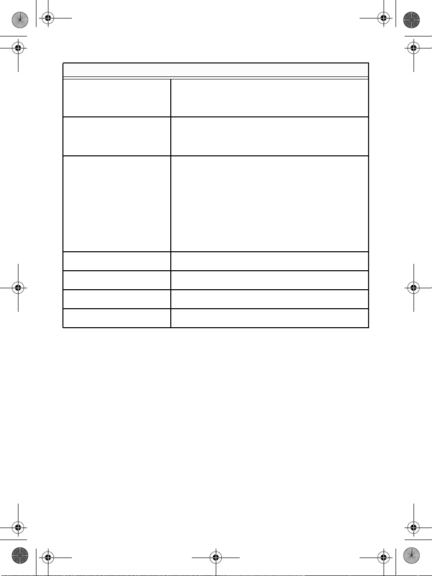
Gigabit switch technical specifications
Standards compatibility IEEE 802.3z 1000BASE-X Gigabit over fiber,
IEEE 802.3i 10BASE-T Ethernet, IEEE 802.3u,
100BASE-TX Fast Ethernet, IEEE 802.3ab
1000BASE-T Gigabit Ethernet, IEEE 802.3x
flow control, IEEE 802.1p priority, DSCP priority
Network interfaces RJ-45-connectors for 10BASE-T, 100BASE-TX,
or 1000BASE-T Ethernet interfaces
Power 100-240V 1.0A AC, 50/60 Hz internal universal
power supply
Power consumption
(full load)
18.2W max. (cable length > 10 meters)
Physical dimensions 328 x 169 x 43.2 mm (12.91 x 6.65 x 1.70 in)
Weight 1.688 kg (3.721 lbs)
Operating environment Temperature: 0° to 50° C (storage: 0° to 70°C)
Humidity: 10% to 90% (storage: 5% to 90%)
Electromagnetic and
safety compliance
CE and CE LVD, Class A; FCC Class A; VCCI
Class A; C-Tick; KCC; CB; CCC; and UL
9
Full_IG.book Page 9 Monday, January 9, 2012 6:11 PM
Gigabit swtich performance specifications
Frame filter/forward rates 14,880 frames/sec. max. for 10 M port
148,800 frames/sec. max. for 100 M port
1,488,000 frames/sec. max. for 1000 M port
Frame forward rate 14,880 frames/sec. max. for 10 M port
148,800 frames/sec. max. for 100 M port
1,488,000 frames/sec. max. for 1000 M port
Network latency Using 64-byte-packets
• 10 Mbps to 10 Mbps: 35 s max
• 100 Mbps to 100 Mbps: 5.4 s max
• 1000 Mbps to 1000 Mbps: 2.8 s max
Using 1518-byte packets
• 10 Mbps to 10 Mbps: 35 s max
• 100 Mbps to 100 Mbps: 5.6 s max
• 1000 Mbps to 1000 Mbps: 2.8 s max
Filtering address table Up to 8 K entries
Jumbo frame Up to 9 KB
MAC address learning Automatic update
RAM buffer 2 Mb
10
Full_IG.book Page 10 Monday, January 9, 2012 6:11 PM
11
Technical Support
Thank you for selecting NETGEAR products.
After installing your device, locate the serial number on the label of
your product and use it to register your product at
www.NETGEAR.com/register. Registration is required before you can
use the telephone support service. Registration through the
NETGEAR website is strongly recommended.
Go to http://support.netgear.com for product updates and web
support.
For complete DoC go to the NETGEAR EU Declarations of
Conformity website at
http://support.netgear.com/app/answers/detail/a_id/11621/.
For GNU General Public License (GPL) related information, go to
http://support.netgear.com/app/answers/detail/a_id/2649.
WARNING: Do not stack equipment, or place equipment in tight
spaces, in drawers, or on carpets. Make sure your equipment is
surrounded by at least 2 inches of air space.
Compliance
This symbol is placed in accordance with the European Union
Directive 2002/96 on the Waste Electrical and Electronic Equipment
(the WEEE Directive). If disposed of within the European Union, this
product should be treated and recycled in accordance with the laws
of your jurisdiction implementing the WEEE Directive.
Full_IG.book Page 11 Monday, January 9, 2012 6:11 PM
NETGEAR, Inc.
350 East Plumeria Drive
San Jose, CA 95134, USA
December 2011
Full_IG.book Page 13 Monday, January 9, 2012 6:11 PM