)NSTALLATION'UIDE
ProSafe
®
8 Port Gigabit PoE Smart Switch™ with 2 fiber SFP GS110TP
Start Here
Follow these instructions to set up your smart switch. Before proceeding with the
smart switch installation, familiarize yourself with the contents of the Resource
CD, especially the reference manuals on your Resource CD.
First, Verify Package Contents
• ProSafe
®
GS110TP Smart Switch
• Rubber footpads for tabletop installation
• Power cord
• 48V/1.25A power adapter
• Wall-mount kit
• Installation Guide
• Smart Switch Resource CD that includes the NETGEAR Device Manager
Utility (Smart Control Center) and GS110TP Hardware Installation Guide. (A
link to the online GS110TP Software Administration User's Manual is on the
Resource CD.)
• Warranty/Support Information Card.
Then, Prepare to Install Your Smart Switch
Prepare a PC with an Ethernet adapter and a CD ROM drive.
Next, Install the NETGEAR Device Manager Utility
(Smart Control Center) on a PC
1. Insert the Resource CD into your CD drive.
2. Run the Setup program to install the Smart Control Center utility. The
Installation Wizard will guide you through the installation.
Next, Connect Your Smart Switch in the Correct
Order
These instructions assume you are using DHCP in your network. If you are using
static IP addressing in your network, configure the switch IP address before
connecting it to your network. In the absence of a DHCP server, the switch will
default to 192.168.0.239 for its IP address.
To configure the switch before connecting it to your network:
1. Set up the PC with a Static IP address in the 192.168.0.x subnet, and connect
the PC to the switch. Then, use the Smart Control Center utility to configure
the switch.
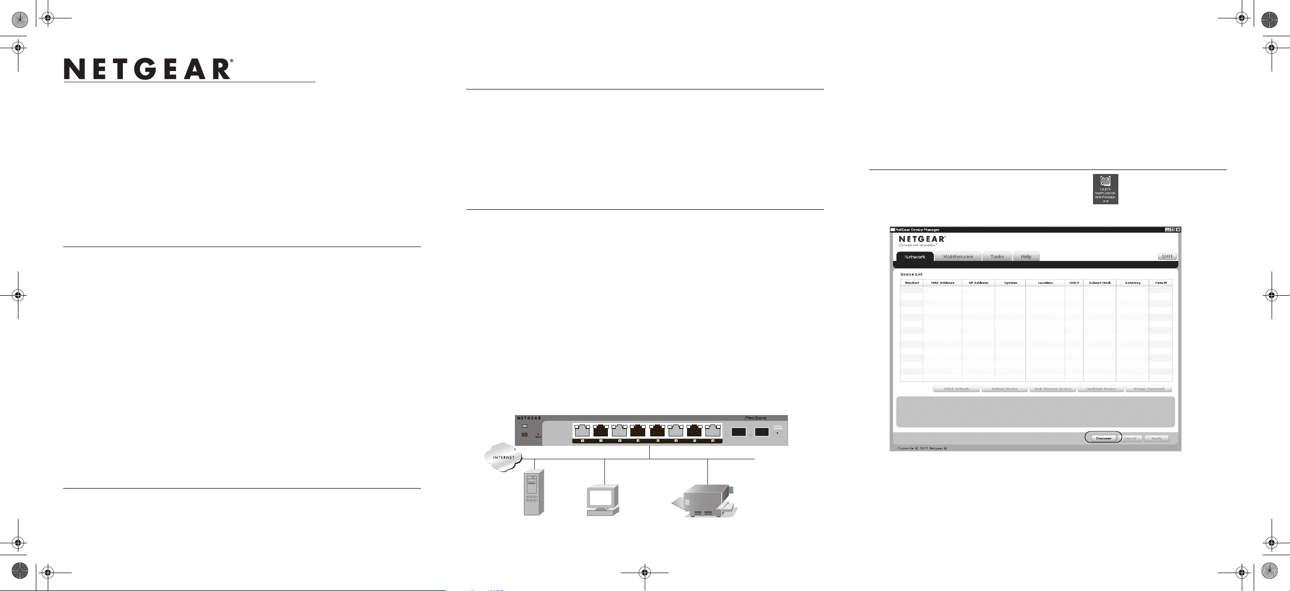
2. Connect each PC to an RJ-45 network port on the switch front panel.
Use category 5 (Cat5) unshielded twisted-pair (UTP) cable terminated with an
RJ-45 connector to make these connections.
Servers Computers Printers
Smart Switch
GS110TP
GS110TP
Power
PoE Max
Link/Act 9F Link/Act 10F
Link/Act PoE
Link/Act Mode
Green = Link at 1000M
Yellow = Link at 100M/10M
Blink = ACT
PoE Mode
Green = PoE Powered
Yellow = PoE Fault
3. Connect the switch to your network.
4. Power on the switch.
5. Verify that the PC with the Smart Control Center utility is on the same subnet
as the switch.
Now, Configure the Switch with the NETGEAR
Device Manager Utility (Smart Control Center)
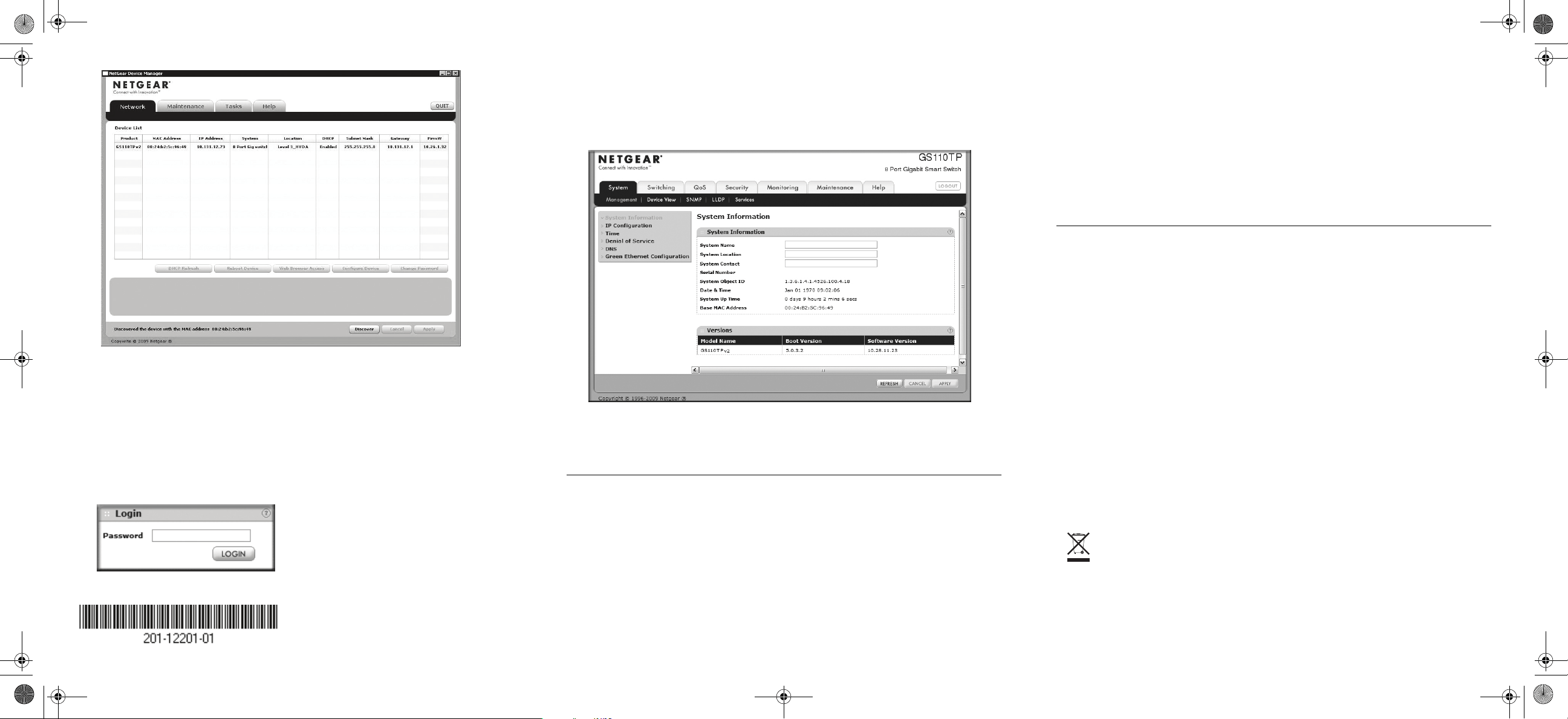
1. Double-click the Smart Control Center icon on your desktop or in
Windows Start menu Programs to run the utility and view this screen.
2. Click Discover to find your switch in the network.
GS110TP_IG_8Feb10.fm Page 1 Tuesday, February 9, 2010 7:15 PM
This symbol was placed in accordance with the European Union
Directive 2002/96 on the Waste Electrical and Electronic Equipment (the
WEEE Directive). If disposed of within the European Union, this
product should be treated and recycled in accordance with the laws of
your jurisdiction implementing the WEEE Directive.
© 2010 by NETGEAR, Inc. All rights reserved. NETGEAR and the NETGEAR logo are registered trademarks of NETGEAR,
Inc. in the United States and/or other countries. Other brand and product names are trademarks or registered trademarks of their
respective holders. Information is subject to change without notice.
February 2010
The Smart Control Center utility finds the switch and displays its MAC
Address, IP Address, and model number. If you cannot configure your switch,
verify that the cable connections are secure, that the IP address configuration
of the PC is in the same subnet as the switch, and click the Discover button.
3. Click to select the line displaying the details of your switch. If there are
multiple switches in your network, be sure to select the one you want to
configure.
4. Click Web Browser Access to view the switch log in screen.
5. Enter the default password of password in lower case letters and click Login.
The switch will display the switch settings main page. Configure the switch
for your network. Consult the Reference Manual on the Resource CD or the
online help in the switch for assistance with configuration procedures.
After you log in to the switch, the main Web Access menu displays.
Use the configuration menu options to configure your switch.
Troubleshooting Tips
Here are some tips for correcting simple problems you may have.
Turn on the computer and switch in the correct sequence.
Follow this sequence. Turn off the switch and computer. First, turn on the
switch and wait two minutes. Next, turn on the computer.
Make sure the Ethernet cables are securely plugged in.
For each powered on computer connected to the switch with a securely
plugged in Ethernet cable, the corresponding Smart Switch port status light
will be lit.
Make sure the network settings of the computer are correct.
In most cases, computers should be configured to obtain an IP address
automatically via DHCP. For help with this, refer to the GS110TP Software
Administration Manual; a link to the online Reference Manual is on the
Resource CD.
If your network uses static IP addresses, be sure the switch and computer are
configured with valid IP addresses.
Technical Support
Thank you for selecting NETGEAR products.
After completing the ProSafe
®
GS110TP Smart Switch setup, locate the serial
number on the bottom label of your product, and use it to register your product at
http://www.NETGEAR.com/register. Registration is required before you can use
our telephone support service. Registration via our website is strongly
recommended.
Go to http://kbserver.netgear.com for product updates and Web support. For
Warranty and Regional Customer Support information, see the Resource CD that
came with your product.
GS110TP_IG_8Feb10.fm Page 2 Tuesday, February 9, 2010 7:15 PM