Loading ...
Loading ...
Loading ...
17
-B-
d
.008
d
.010
2' x 2' Sheet Metal Shield on
Brick or Masonry Walls
Outside of
Building
Terminals with 1/2" Mesh
Protective Screens Inside and
Termination Restrictors Inside.
Note: Termination Restrictors
used on 75 Gallon
models ONLY.
Inside of
Building
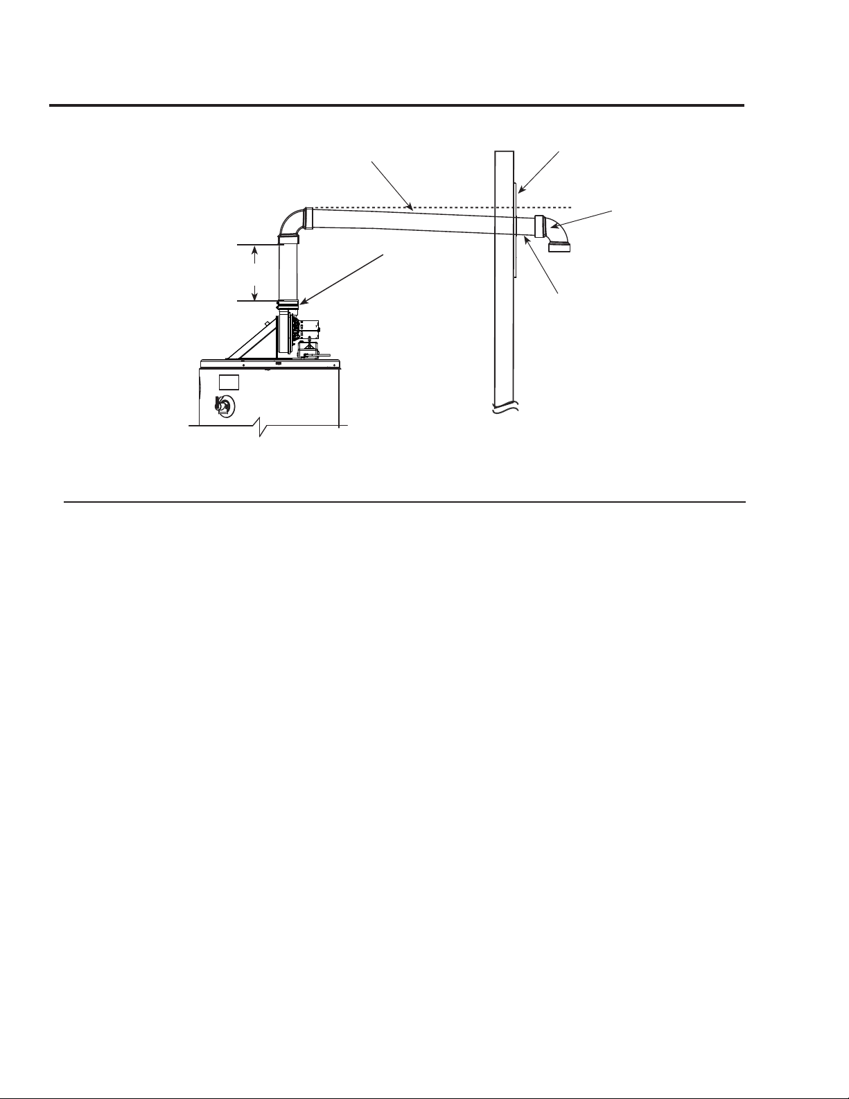
Horizontal Vent Terminal Installation
Slope horizontal pipe downward 1/8"
per foot (10 mm per m) min.
Min 1'
Optional -
Condensate
Management Drain
Port*
*See Condensate Management Sec-
tion for additional information about
optional piping.
Vertical Vent Terminal Installation
The location of the vent terminal depends on the following
minimum clearances and considerations.
1. Minimum 12 in. above roof.
2. Minimum 12 in. above anticipated snow level.
3. Maximum 24 in. above roof level without additional sup-
port for vent.
4. Four (4) ft. from any gable, dormer or other roof structure
with building interior access (i.e., vent, window, etc.).
5. Ten (10) ft. from any forced air inlet to the building. Any
fresh or make-up air inlet such as a dryer or furnace area is
considered to be a forced air inlet.
6. Maintain a minimum distance from the vent terminal of
not less than 12 in. above grade or average snowfall, which-
ever is greater.
Read these instructions thoroughly and make sure you un-
derstand all steps and procedures before proceeding with the
installation.
Determine the locations for the vent terminal then make a
hole through the roof and interior ceiling(s) to accommodate
the vent pipe.
Assemble the vent pipe assembly.
Install the vent system and attach it to the blower exhaust
coupling on the water heater’s blower assembly.
Horizontal lengths of the vent system must slope towards the
water heater a minimum of 1/8 in. per foot (10 mm per m).
• Support vertical and horizontal lengths of the vent system
as previously mentioned.
Determine the vent terminal height and cut the pipe accord-
ingly.
• Insert lengths of vent pipe through the ceiling wall as
shown.
• Install adequate ashing where the vent pipe passes
through the roof.
• Place the supplied mesh metal screen inside the vent ter-
minal then connect a short piece of pipe approximately 3 in.
between the terminal and elbow.
NOTICE: For cold climates the screen may be removed.
NOTICE: This water heater is supplied with a vent ter-
mination restrictor. The restrictor helps the water heater
achieve peak eciency when the water heater is installed
using 3 in. diameter pipe at the minimum equivalent vent
length of 10 ft.
IMPORTANT: DO NOT install the termination restric-
tor in equivalent vent lengths longer than 10 ft. or on any
other Power Vent model.
Rear of termination
4" from outside
wall to back of
elbow.
Loading ...
Loading ...
Loading ...