Loading ...
Loading ...
Loading ...
16
NOTICE: All pipe, fittings, solvent cement, primers and procedures must conform to American National
Standards Institute and American Society for Testing and Materials (ANSI/ASTM) standards.
Additional
Vent Location
Considerations
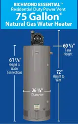
DO NOT install the vent terminal under any patio or deck.
To help prevent moisture from freezing on walls and under eaves,
DO NOT locate the vent terminal on the side of a building with
prevailing winter winds.
When terminating the vent pipes through brick or masonry
surfaces, the installation of a rust resistant sheet metal backing
plates behind the vent terminal is recommended.
DO NOT locate the vent terminal too close to shrubbery, as flue
gasses may damage them.
Caulk all cracks, seams and joints within 6 ft. of the vent
terminal.
Insulate vent pipe exposed to cold conditions (attics, crawl
spaces, etc.) with inflammable material to help prevent moisture
from accumulating in the vent pipe.
Support horizontal sections of the vent pipe every 4 ft. DO NOT
rigidly secure the vent system. Provisions must be made to allow
for expansion and contraction of the vent system.
DO NOT install the vent terminal less than 1 ft. above grade or
average snowfall whichever is greater.
Permanently seal annular openings around the vent system
penetration using approved materials to prevent entry of
combustion products into the building.
If soffit vent is too
close, block off and
install new vent at
another location
Inside
corner
Caulk
Caulk
Caulk
6’ caulk
zone or to edge of window
etc., starting within 6 ft.
Rising moisture will
collect under eaves
4’
6’ caulk zone
2’ sq. sheet metal plate on
brick or masonary surface is recommended.
6’
WARNING: Moisture in the flue gas will condense as it
leaves the vent terminal. In cold weather this condensate can
freeze on the exterior wall, under the eaves and on surrounding
objects. Some discoloration to the exterior of the building is to be
expected. However, improper location or installation can result in
severe damage to the structure or exterior finish of the building
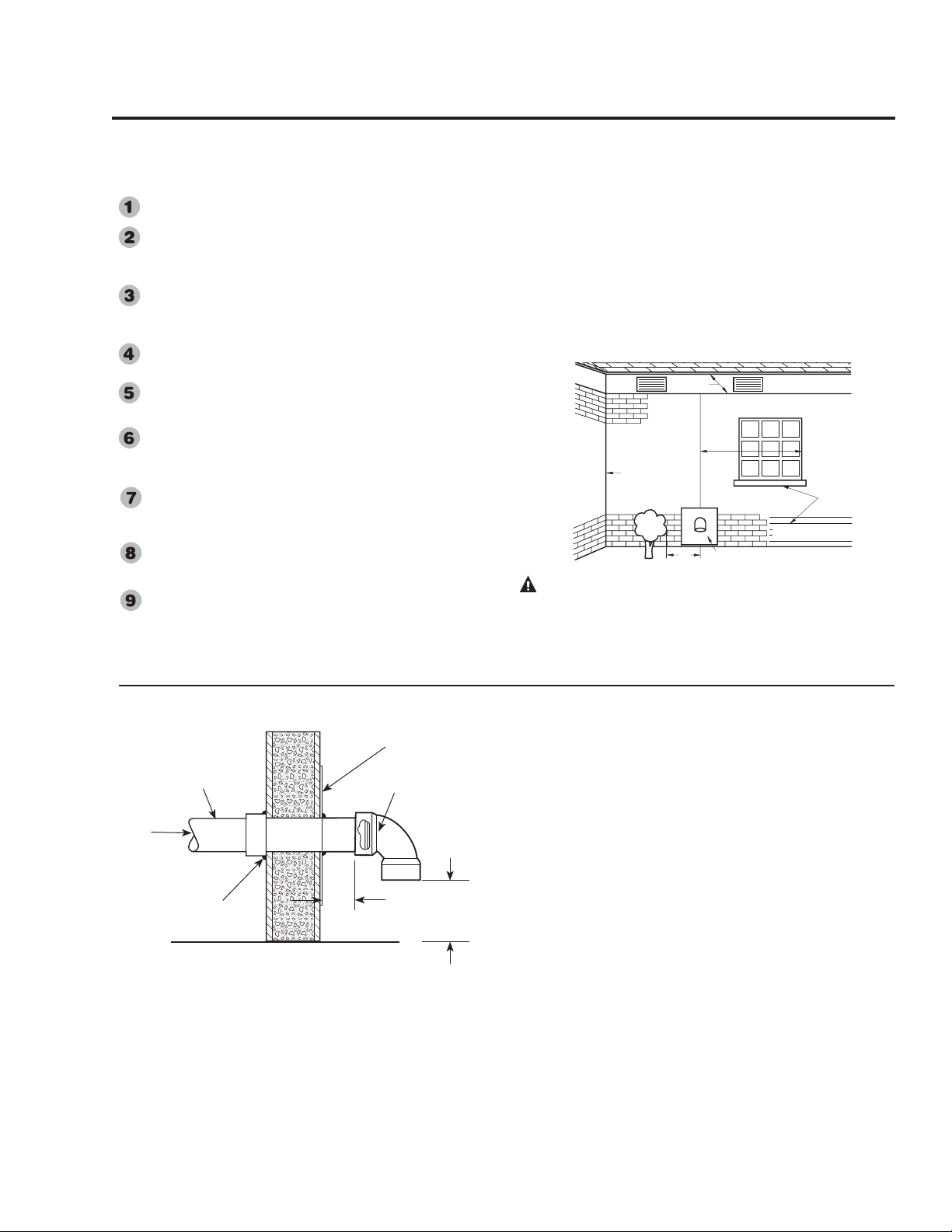
Horizontal Vent Terminal Installation
Read these instructions thoroughly and make sure you understand
all steps and procedures before proceeding with the installation.
Determine the locations for the vent terminal then make a hole
through the exterior wall to accommodate the pipe.
Insert lengths of vent pipe through the wall as shown.
Allow sufficient length of pipe to extend beyond the exterior wall
of the building for attachment of the vent terminal.
Place the supplied mesh metal screen inside the vent terminal
fitting.
NOTICE: For cold climates the screen may be removed.
Connect the terminal to the vent pipe which is extending out of the
building.
Ensure that the back of the supplied terminal is flush with the
outside wall surface.
Complete the installation of the remainder of the vent system
and attach it to the blower exhaust coupling on the water heater’s
blower assembly.
Horizontal lengths of the vent system must slope downward a
minimum of 1/8 in. per foot.
IMPORTANT: When the vent system cannot be sloped
away from the water heater or, if the vent system has vertical
section(s), then all horizontal sections must slope upwards a
minimum of 1/8 in. per foot;
DO NOT use unequal diameters of pipe and fittings for the vent
system except as defined previously
Support vertical and horizontal lengths of the vent systems as
previously mentioned.
NOTICE: This water heater is supplied with a vent
termination restrictor. The restrictor helps the water heater
achieve peak efficiency when the water heater is installed using
3 in. diameter pipe at the minimum equivalent vent length of
10 ft.
IMPORTANT: DO NOT install the termination restrictor
in equivalent vent lengths longer than 10 ft. or on any other
Power Vent model.
Installing the water heater
• DO NOT terminate near soffit vents or crawl space or other area
where condensate or vapor could create a nuisance hazard or cause
property damage.
• DO NOT locate the exhaust vent terminal where condensate or
vapor could cause damage or could be detrimental to the operation
of regulators, relief valves, or other equipment.
• DO NOT locate the exhaust vent terminal over public area or
walkways where condensate or vapor can cause nuisance or
hazard.
• DO NOT locate the vent terminal in proximity to plants/shrubs.
2' x 2' Sheet
Metal Shield on
Brick or Masonry
Walls
Outside of Building Wall
From
Water Heater
Vent Pipe
Pipe Coupling
Vent Terminal with
Mesh Protective
Screen Inside
4"
(10 cm)
12"
(30 cm)
Loading ...
Loading ...
Loading ...