3-minute re-start delay protection to compressor and other multiple protection functions.
Unique exhaust hose and fasteners, convenient installation.
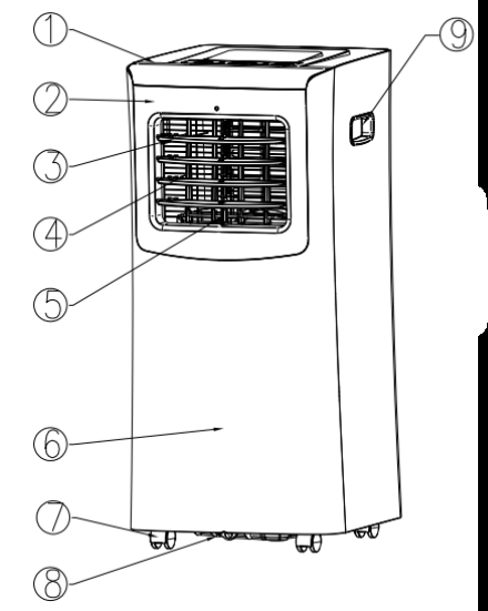
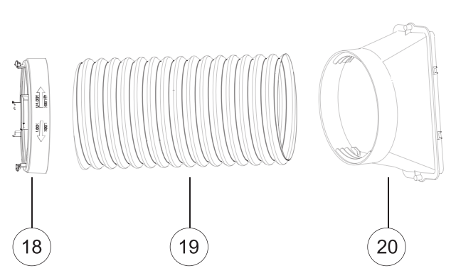
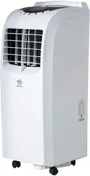
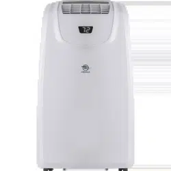
2. Identification of Parts:
1.
Top panel
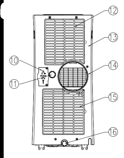
11.
Upper drain hole
2.
Front panel
12.
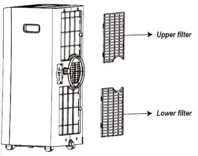
Upper filter
3.
Horizontal louvers
13.
Back shell
4.
Vertical louvers
14.
Exhaust hose connector
5.
Front shell connector
15.
Lower filter
6.
Front shell
16.
Lower drain hole
7.
Universal wheel
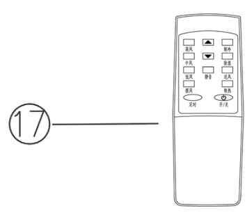
17.
Remote control
8.
Chassis
18.
Round Connector
9.
Handle
19.
Exhaust hose
10.
Universal plug protective sockets
20.
Adapter
Operation and Settings
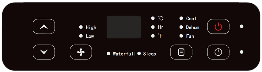
Control Panel
Control Panel list
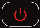
On/Off button
Mode button
Up button
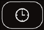
Timer button
Fan speed button
Down button
Timer indicator
Fan speed indicator
Water-full indicator
Cool mode
Fan mode indicator
Dehumidify mode indicator
Sleep mode indicator
Power indicator
Celsius temperature indicator
LED display window
Timer indicator
Fahrenheit temperature indicator
Control Panel Operation
A. Turn on the unit:
Connect the power supply and all indicators on the control panel will light up with reminding music; LED display window will show ambient temperature ranging from 10- 35°C. On/Off button will be in red color, and the unit is standby for operation.
Press the On/Off button, the unit turns on with reminding music sounded, On/Off button will in green color, and operate in Cool Mode automatically, temperature set at 24°C, and fan runs at high speed.
B. Select operating mode
Press the Mode button to toggle among the operating options: Cool - Dehum - Fan. The corresponding indicator will illuminate:
C. To Set the Temperature:
The temperature can be set between 17°C and 30° C when the air conditioner is in Cool mode.
D. Fan speed button
The fan speed can be adjusted from Low speed to High speed when the air conditioner is in operation.
NOTE: The fan speed cannot be adjusted when the unit is in Dehum mode.
E. Stand-by
Press On/Off button again, the unit will stop working with reminding music, and On/Off button will be in red color.
Working principle for each mode and function
1. Cool mode:
When room temperature is 1°C higher than setting temperature, the compressor and fan will start working.
When room temperature is 1°C lower than setting temperature, the compressor will stop working and fan keep working at original speed.
Room temperature can be set within a range of 17-30°C and fan speed can be adjusted to high or low level.
On/Off time can be set.
E1, E2 & E4 protection (see Troubleshooting).
Water-full warning protection.
2. Fan mode:
Fan runs at set speed, and compressor will not work.
Fan speed can be adjusted to high or low level.
Room temperature will automatically show on LED display with range 10-35°C.
Room temperature can’t be adjusted.
On/Off time can be set.
3. Dehumidify mode:
Fan will run at low speed automatically, and the speed can’t be adjusted.
Room temperature can’t be adjusted.
Room temperature will automatically show on LED display with range 10-35°C
On/Off time can be set.
E1, E2 & E4 protection (see Troubleshooting).
Water-full warning protection.
4. Sleep mode:
Under cooling mode, press “Timer” + “Down” buttons together, the unit auto enter into “Sleep” mode.
Fan will turn to low speed automatically and can’t be adjusted.
Set temperature will increase 1 °C when unit running in 2 hours, increase 1 °C again in another 2-hour working, then keep set temperature unchanged further.
Room temperature will automatically show in LED display with range 10-35°C.
On/Off time can be set.
E1, E2 & E4 protection (see Troubleshooting).
Water-full warning protection.
5. Timer Operation
Press “Timer” button to set automatic OFF time while unit is running, “Timer” will light up.
The unit will be off automatically when the set time is off, and “Timer” will be off, room temperature is shown on LED display window.
Press “Timer” button to set automatic ON time while unit is off, “Timer” will light up.
The unit will turn on automatically and working at original mode when the set time is over, “Timer” will be off, room temperature is shown on LED display window.
When press “Timer'’, “Timer”& “Hr” will light up, LED display window will flash under half second frequency, press “Up” or “Down” buttons within 5 seconds to finish timer setting, set time will flash 5 seconds for confirmation and “Hr” will turn off, then room temperature will be shown on LED display window.
Under “Timer” function, press “Timer” once to check time remained. Timer indicator keep light up; press “Timer” twice within 5 seconds to cancel timer, “Timer” will turn off.
Only final setting is effective if repeated setting.
The time can be adjusted within a range of 1-24 hours, press “Up” or “Down” button to increase or decrease 1 hour.
Unit will not change working mode after timer setting. Timer will not stop by other functions.
Timer will be ineffective if any operation from control panel or remote control to turn on or turn off the unit.
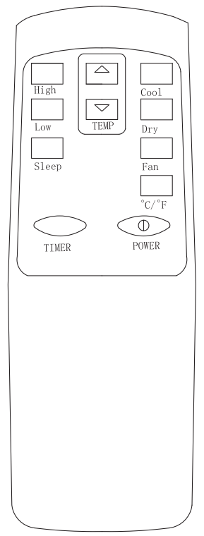
Remote Control Operation
Power Button: press this button to start unit when it is energized or stop the unit when it is in operation.
Timer Button: press this button to set unit automatic on and off time.
High Button: press this button to select high speed of fan running (except dry and sleep modes) Button:
Low Button: press this button to select low speed of fan running.
TEMP UP Button: press this button to increase temperature or timer setting.
TEMP Down Button: press this button decrease temperature or timer setting.
Cool Button: press this button to select “Cool” mode.
Fan Button: press this button to select “Fan" mode.
Dry Button: press this button to select “Dry” or “dehumidifying” mode.
Sleep Button: press this button to select “Sleep” function under cooling mode.=
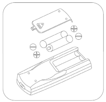
Before using your remote, install the AAA batteries into remote control.
Press and glide the battery cover on the back of the remote control, then you can remove the cover.
Insert two new alkaline AAA batteries into the battery compartment. Be sure to note the proper polarity.
Reattach the battery cover and make sure the locking tab clicks into place.
Be sure to note proper polarity of batteries
Notes:
Use alkaline batteries only. Do not use rechargeable batteries.
When replace batteries, always replace both batteries with new batteries, do not mix old and new batteries.
If the air conditioner will not be used for an extended period of time, remove the batteries from the remote control.
CAUTION
If the liquid from the batteries gets onto your skin or clothes, wash it well with clean water, do not use the remote control if the batteries have any leakage.
If you eat the liquid from the batteries, brush your teeth and see doctor. The chemicals in batteries could cause burns or other health hazards.
Multiple Protection Functions
1. Anti-freeze protection function
Compressor, water spraying motor will turn off when compressors running over 10 minutes and tube temperature (Tp) is continuously ^2°C for 20 seconds under cooling mode, E4 will show on LED display window, the unit initiates the anti-frost protection and all buttons on control panel (except for power button) are inactive.
Once the tube temperature =8°C, the protection is relieved to recover into original status, and compressor apply to 3-minute delay protection.
2. Water-full safety alarm and shut -off protection function:
Warning sounds when the water volume reached its alarm level in water tank, and unit is automatically stop working, both water-full indicator and “FL” on LED window is flashing. You need to drain the condensate for unit to automatically recover operation. (For more information about how to drain, refer to the “Drainage Instruction” please).
3. Delay protection function of compressor
This unit offers restart protection to compressor. Except that the compressor may start immediately when the unit is energized at first time, there is 3-minute start delay after compressor is shut down.
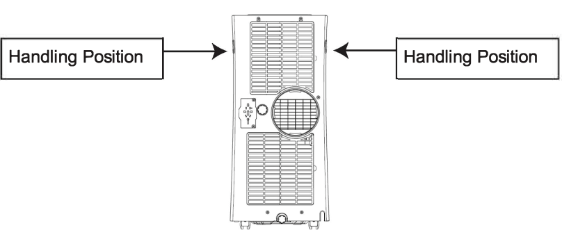
Handling and Transportation
1. Handle and move the unit
Hold the top of the air outlet window in front panel with one hand and the handle at the top of back panel with another hand, then move the unit in upright position.
Note:
Do not hold the horizontal louvers by hand.
Make the unit in the upright position whatever handling or moving it.
Drain the water in the unit completely to prevent water leakage and wet the floor or carpet before handling or moving the unit.
Take away the remote control before handling or moving the unit
Installation & Adjustment
Warning:
Keep this mobile air-conditioner in upright position at least 2 hours before first installation.
This air-conditioner may be moved indoors conveniently; keep the unit in upright position while moving it. The air-conditioner shall be placed on flat surface.
Do not install or operate this air-conditioner in bathroom or other wet environments.
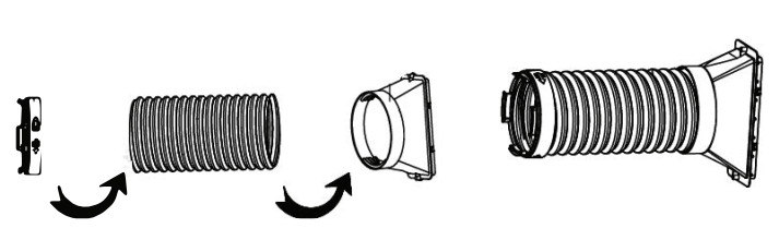
1.1 Installation of exhaust hose assembly and its adapter
Take out the exhaust hose assembly and its adapter from plastic bag.
Extend the exhaust hose at one end, screw the round end of adapter into exhaust hose at anticlockwise direction
Note: Screw adapter into right position, at least 3 laps, to keep good connection of exhaust hose assembly and its adapter
1.2 Installation of the exhaust hose assembly into unit
Determine window seal-plate position, vertical or horizontal direction.
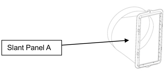
If window seal-plate will be in horizontal position, the slant panel A of adapter should be upwards.
If window seal-plate will be in vertical position, and will be at left side of window, the slant panel A of adapter should be at right direction.
If window seal-plate will be in vertical position, and will be at right side of window, the slant panel A of adapter should be at left direction.
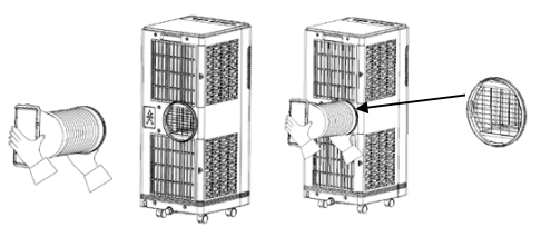
1. Take two ends of exhaust hose and its adapter assembly
2. Put front end of exhaust hose assembly onto jugged position of exhaust outlet of back panel. Remark: Keep the right direction of slant side A of adapter, for ease installation of window seal-plate.
3. Hold the unit by one hand, carry the exhaust hose assembly with another hand and push it into unit gently, for good lock of two parts.
Remarks:
Keep the right direction of slant side A of adapter, for ease installation of window seal-plate.
Keep exhaust hose assembly be strongly locked by fasteners in exhaust outlet to avoid its fall off.
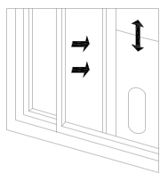
1.3 Installation of window seal-plate
Open the window in half, put the seal-plate into window, determine in vertical or horizontal position according to window open direction.
Extend seal plate parts, adjust it to the length of window and fix it with screws then.
Remarks:
Keep two ends of window seal-plate to meet the window edges well, to assure seal effect.
Fix the screw in good position.
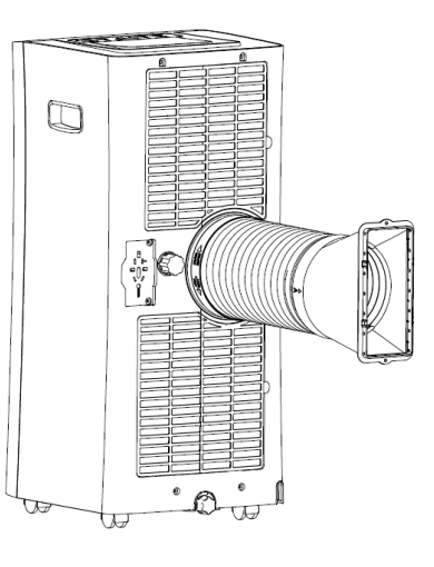
1.4 Installation of the unit
Move the unit together with its exhaust hose assembly in front of the window and keep the unit at least 50cm away from the walls or other objects.
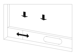
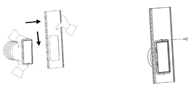
Install the rectangle end of exhaust hose adapter into the corresponding rectangle hole in window seal-plate assembly, fix it with screw and close the window (as Photo).
Align the 4 openings on window seal-plate with corresponding 4 openings on exhaust hose adapter and set them together, then slide adapter downwards, to make 2 set of openings locked for 2 parts good connection.
Lock self-tapping screw
Remarks:
Slide the adapter downwards and assure the adapter installed in good position.
Lock the screw tightly to avoid fall off.
Exhaust hose can’t be bent or with flexure higher than 45°, in order to keep good ventilation of exhaust hose.
Important notes:
The exhaust hose is 280mm-1500mm long and which is determined by the specification of the air-conditioner (s). Do not use prolonged the hose or replace it with other different hoses as this may affect the functions of the air-conditioner. The exhaust hose must be smooth or it may lead air-conditioner overheat and trip because exhaust hose is obstructed.
Drainage Instruction
This portable air conditioner has two drain ports - an upper drain port and a lower drain port. It also has two drainage methods that can be used - manual drainage and continuous drainage.
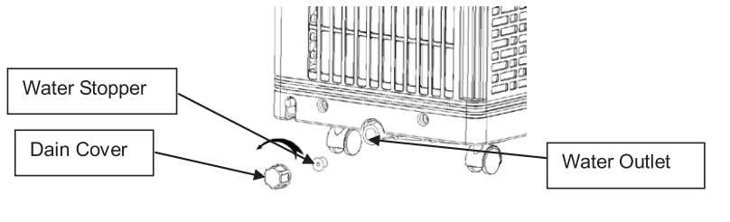
1. Manual drain:
This unit is designed with a highly efficient self-evaporative system and it is suggested to use manual drainage in cooling mode. Condensate will recycle in the unit to cool the condenser and enhance cooling performance. However in extreme humidity, the water tank in the chassis will fill up and “FL” will show on the LED display. When this happens the water tank needs to be drained manually from lower drain port.
Put a shallow tray below the lower drain port at the back of the unit.
Screw off the drain port cover and then remove the water stopper to allow water flow into the tray.
After water has stopped flowing, plug in the water stopper back in and screw the drain port cover back onto the drain port tightly.
NOTE:
To avoid leaks, if it is necessary to move the unit always turn off the unit and make sure it is drained properly before moving.
If the drain port cover or water stopper are damaged during use, they should be replaced with new ones.
Tilt the unit slightly backwards when draining.
If the shallow tray has insufficient capacity to hold all the water that is draining, block the drain port with the water stopper before the tray is full, empty the tray, and then restart the draining process.
The water stopper and drain port cover must be fitted properly to avoid leakages.
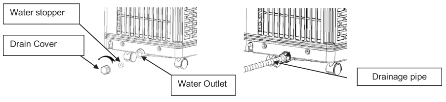
2. Continuous drain:
Screw off the drain cover and unplug the water stopper.
Connect drain hose
Pull the drain hose to bathroom or outdoor.
Notes:
Drain hose must be installed before unit starts working.
When unit is operating in cooling mode, to ensure enough water to recycle in the unit to cool condenser and enhance cooling performance, so it is not suggested to use continuous drainage
Put the drain hose in an inaccessible place, not higher than drainage hole and keep drain hose straight without any flexure.
Keep the drain cover and its stopper properly installed when continuous drainage is adopted.
Maintenance and Service
Turn off the unit and pull out the plug before maintain or send the unit to service center.
1. Surface cleaning
Clean the unit surface with wet and soft doth, but do not use chemical solvents such as alcohol and gasoline to avoid any damage to unit.
2. Filter deaning
Clean the filter every two weeks, otherwise it would influence the unit performance if filter clogged with dust.
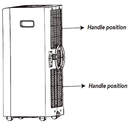
2.1 How to clean filter
Grip the filter handle and take it out gently in corred direction shown by the arrow.
Take out filters of back panel at first then side panel.
Clean the filters gently in warm water (about 40°C) mixed with detergent, and dry in the shade
Use even force to take out the filter to avoid any twist or damage to filter.
Notes:
Do not squash the mesh.
Do not hit the mesh with sharp objects or brush.
2.2 Installation of the filter
Special note: Be sure to install the filters to side panel at first then the filter into back panel.
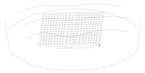
1. Aim the end of the filter toward slot then push filter in even force gently into slot.
Notes:
Install the filter with opposite direction of removal.
Install the filter into place gently to avoid any damage.
2. Clean of handle position and remote control storage area.
Take out the remote control
Clean the handle position and remote control storage area with wet and soft cloth.
Note: Do not drip water into the unit.
End of Season Storage
1. Screw off the drain cover, and then pull out the stopper to drain water completely.
Note: the tilt angle of the unit must be ≤30
2. Keep the unit running in fan mode half day to dry inside of unit completely to prevent from going mouldy.
3. Turn off the unit, pull out plug then wrap the power cord around the wire-winding pillar, insert the plug into the universal fixing hole at the back panel of the unit, install the water plug and drain cap.
4. Remove the heat exhaust hose assembly, clean and keep it properly.
Notes:
Hold the exhaust hose assembly with both hands when removal.
Push the fasteners aside on exhaust air outlet using your thumbs, then pull out exhaust hose assembly.
5. Pack the air-conditioner properly with soft plastic bag and put it in dry place with appropriate dust-proof measures and keep the unit away from children.
6. Take out the batteries from the remote control and keep it properly.
Note: Assure the unit is stored in a dry place. All accessories of the unit shall be properly protected together.
Troubleshooting
Please check the unit and suggestions below before asking for professional service, but never dismantle or repair the unit by yourself, it may cause harm to you and your property.
Trouble
Cause
Remedy
The unit fails to start up
Power supply failure
Connect the unit to a live socket and turn it on.
Water-full and its indicator lighting up
Drain the water stored in the unit.
Ambient temperature too low or too high
It is recommended to use this unit between 10-35°C (50-95°F.)
The room temperature is lower than the set temperature in cooling mode.
Change the set temperature
Bad cooling effects
There is direct sunlight
Close the curtain
The doors and windows are open, the room is crowded or there are other heat sources
Close the door and window, remove other heat sources, and add new air-conditioners
Dirty filter
Clean or replace the filter.
Air inlet or air outlet clogged
Remove the obstruction
High noise level
The unit is being placed at uneven surface.
Put the unit at a flat and firm place (may reduce noise)
The compressor does not work
Initiation of overheat protection.
Wait until the temperature decrease, the unit will re-start automatically
The remote control does not work
Too long distance
Bring the remote control close to the air-conditioner and ensure airs at signal receptor on unit.
The remote control didn’t aim at signal receptor on unit.
The batteries have no electricity
Replace the batteries
LED displays error code “E1”
Tube temperature sensor failure
Check the tube temperature sensor and related circuits
LED displays error code “E2”
Room temperature sensor failure
Check the room temperature sensor and related circuits
LED displays error code “E4”
Anti-freeze protection
Restore the functions automatically once anti-freeze protection is over.