
Loading ...
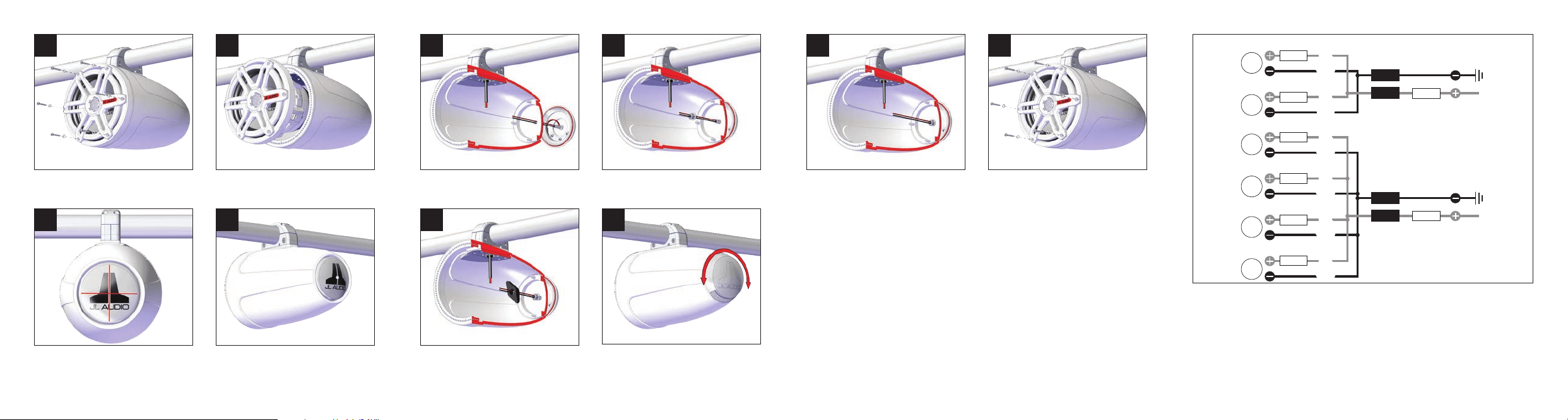
Remove the six #8 x 1-1/4” Pan Head Screws and six #8
Flat Washers that secure the speaker to the enclosure.
1
Connect the LED wires from the LED Light Cap to the
LED wires entering the enclosure. Refer to the wiring
charts on the opposite page for details. DO NOT install
the fuse holders inside the enclosure.
9
Using the exterior angles of the JL Audio logo as a
guide, mark the center of the rear aluminum logo cap,
as shown. Using a punch tool, make an indent in the
aluminum logo cap on the center mark.
3
Slide the M10 Locknut Tool over the LED wires and onto
the M10 x 1.5 Nylon Insert Flange Locknut.
7
Disconnect the speaker wiring and speaker LED
wiring (if equipped), and remove the speaker from the
enclosure.
2
Slide an M10 x 1.5 Nylon Insert Flange Locknut over the
LED wiring, and hand-tighten onto the readed Stud.
6
Using a 7/16” drill bit, carefully drill through the center of
the rear aluminum logo cap, into the enclosure. File any
sharp edges.
4
Reconnect the speaker wiring, and reinstall the speaker
using the six #8 x 1-1/4” Pan Head Screws and six #8
Flat Washers.
10
Rotate the LED Light Cap to the desired angle. Using the
M10 Locknut Tool, fully tighten the M10 x 1.5 Nylon Insert
Flange Locknut until the O-ring is fully compressed and not
visible to ensure the unit is properly sealed. Remove the M10
Locknut Tool from the enclosure.
8
Pass the LED wires and readed Stud on the back of the
LED Light Cap through the drilled hole, and position the
cap ush against the back of the enclosure.
5
• For marine installations, do not connect the LED lights
to the vessel’s navigational lighting circuits.
• For short-circuit protection, install a supplied fusehold-
er onto EACH LED Light Cap’s RED (+12V) LED power
connection lead.
• Connect all RED (+12V) leads together (parallel) and
connect to a switched +12V supply. Connect all
GREEN (GND) leads together and connect to a
negative ground or to the NEGATIVE battery post.
• We recommend activating the LEDs thru a lighting
circuit that supplies +12V via an existing switch. If an
existing switched circuit is not available, you may install
a dedicated toggle/rocker style switch that will supply
positive (+12V) power. Fuse this connection according
to how many LED circuits you have (LED circuits x
150 mA).
[GND]
LED
[+12V]
Blue
Yellow
Blue
Yellow
Red
Black
Red
Black
LED
Fuse
Fuse
Fuse
[GND]
[+12V]
Blue
Yellow
Red
Black
Blue
Yellow
Red
Black
Blue
Yellow
Red
Black
Blue
Yellow
Red
Black
LED
LED
LED
LED
Fuse
Fuse
Fuse
Fuse
Fuse
Example: One pair of LED circuits
connected in parallel.
Example: Two pairs of LED circuits
connected in parallel.