Loading ...
Loading ...
Loading ...
air
regul.
4mm
13 mm
2mm
6mm
15 mm
15 mm
Regulating the minimum flame
After lighting the burners, turn the control knob to the minimum setting and then remo-
ve the knob (this can easily be removed by apply a gentle pressure).
Using a small «Terminal» type screwdriver the regulating screw can be adjusted as in
Fig. 8. Turning the screw clockwise reduces the gas flow, whilst turning it anticlockwise
increases the flow – Use this adjustment to obtain a flame of approximately 3 to 4 mm
in length and then replace the control knob.
If GPL (cylinder) gas is being used, turn the screw clockwise right to the end of the
travel of the by-pass.
Screws
regulating
Gas tap calibrating screws
(flat head slot type)
INSTRUCTIONS FOR USE
Using the gas Burner
To ignite the burners, place a lighted taper close to the burner, press in and turn the
control knob anti-clockwise.
If the burners have not been used for a couple of days, wait for a few seconds before
lighting the burner, this will allow any air present in the pipes to escape.
For appliances equipped with electronic ignition, simply press down and turn the con-
trol knob to the position marked with a star
★
.
After the burner ignites, turn the knob to the control setting required.
The ignition is by repetitive spark generation; in case the burner does not light at once,
keep the knob in the ignition position for a maximum of 5 seconds.
If the burner does not ignite in this time, switch off the control knob and repeat the opera-
tion again.
As a safety device, some models automatically cut off the gas supply if the flame is
ac-
cidently extinguished. In this case, push and rotate the control knob until the
★
position
and keep it held
down for approx 5-6 seconds.
The burner will then remain lit.
39
Fig. 8
Working
burner
large
double ring
medium
small
fish
maxi
Ø injector
1/100 mm
120
2x94
93
80
2x94
2x94
Ø injector
1/100 mm
80
2x65
61
54
2x65
2x65
Qn
kW
2,65
3,3
1,5
1,1
3,3
3,3
l/h
G20
252
314
143
105
314
314
g/h
G30
193
238
109
80
238
238
Qn
kW
2,5
3,1
1,45
1,05
3,1
3,1
l/h
G25
277
343
161
116
343
343
Qmin.
kW
0,570
0,900
0,380
0,250
0,900 G30
1 G20/G25
0,900
air
regul.
4mm
13 mm
2mm
6mm
15 mm
15 mm
air
regul.
2mm
0mm
5mm
4mm
0mm
0mm
G20 G30 G25 G31
G30G20/G25 G20/G30 G25
Quota «X» depending
on type of gas
Table of gas consumption 1W = 0,860 kcal/h
air
regul.
5mm
15 mm
7mm
6mm
15 mm
15 mm
38
Adapting the hob to different types of gas
To adapt the Hob for use with different types of gas, carry out the following instructions:
— remove the grids and burners
— insert the hexagonal spanner (supplied) into the burner support (Fig. 5)
— unscrew the injector and replace it with one suitable for the gas to be used (see
Table page 28).
When you have carried out the new gas regulation, replace the old gas rating plate
on your appliance with one (supplied with hob) suitable for the type of gas for which
it has been regulated.
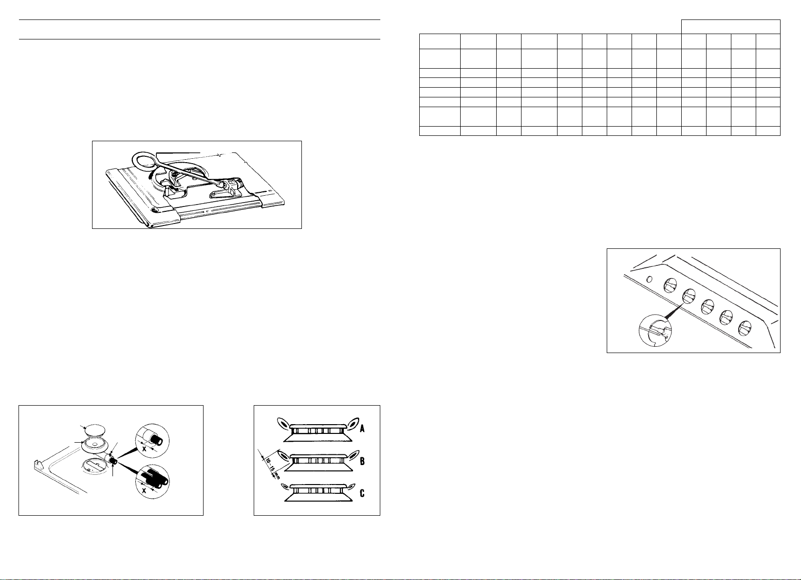
REGULATING THE BURNERS
Flame Combustion
For maximum efficiency from the burners, the correct combustion of the flame is ne-
cessary. A good flame must be well aligned and without yellow tips (Fig. 7/B). If there
is insufficient air, the flame will be uneven with yellow tips (Fig. 7/A). If there is too much
air, the flame will be very short and bright (Fig. 7/C). In these cases the combustion
must be adjusted by re-fitting the carburation tube to the Venturi (where there is insuffi-
cient air) or removing the carburation tube (in the case of too much air). To position
the carburation tube, the fixing screws must be loosened, and retightened when the
satisfactory combustion is obtained.
Fig. 6 Fig. 7
BURNER CAP
BURNER
AIR REGULATION
SCREW
FIXING
SCREW
SMALL
MEDIUM
LARGE
DOUBLE RING
MAXI
FISH
For dimensions «X» see attached table
Hexagonal spanner
Fig. 5
Loading ...
Loading ...
Loading ...