SereneLife SLGATEOP Sliding Gate Motor
Product's Documents
Below are documents related to this product, you can read online or download:
- Owner's manual - (English) Read Online | Download pdf

Owners' Guide The Soft Top
Automatic Sliding Gate Motor is applicable to gate weight less than 600kg, and length of the sliding gate less than 8m. The drive mode adopts the sprocket and chain transmission. This gate opener must be installed inside the enclosure or yard for protection.

Size of embedded hole
Preparation work before installation
Please make sure that the sliding gate is correctly installed, the gate rail is horizontal, and the gate can be manually moved smoothly before installing the gate opener.
Cable installation
In order to guarantee the normal operation of the gate opener and protect the cables from damages, please bury the motor & power cable and controlling cable separately with two PVC tubes.
Concrete pedestal
Please precast a concrete pedestal with the size can be 500mm x 300mm, depth be 250mm in advance, so as to firmly install Automatic Sliding Gate Motor. Please make sure the distance between the gate and gate opener is appropriate before casting the pedestal.
Embedded screws

Main engine installation
a. Dismantle the plastic housing on the main engine before installation and keep relevant fasteners properly;
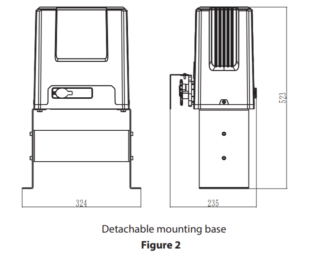
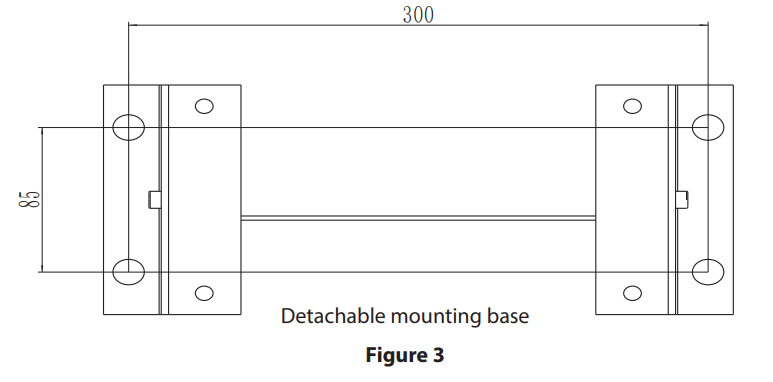
b. If you select the detachable mounting base, please assemble the base first as shown in Figure 5;

c. Assemble the machine engine to the mounting base as shown in Figure 6;
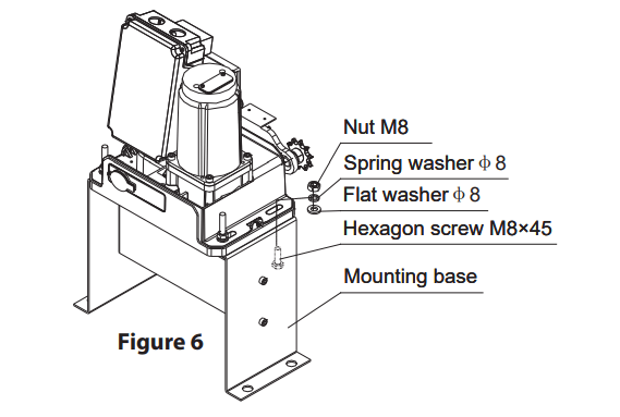
d. Prepare the power line for connecting the mounting plate to the main engine (the number of power supply cable cores should not be less than 3 PCS, the sectional area of cable core should be over 1.5mm² and the length should be determined by users according to the situation on installation spot)
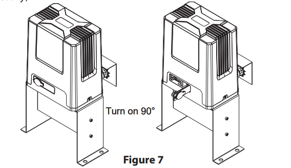
e. Unlock the main engine before installation, the unlock method is: take out the key cover, insert the key, and open the manual release bar till it rotates by 90° as shown in Figure 7. Then turn the output sprocket and the sprocket can be rotated easily;
Chain installation
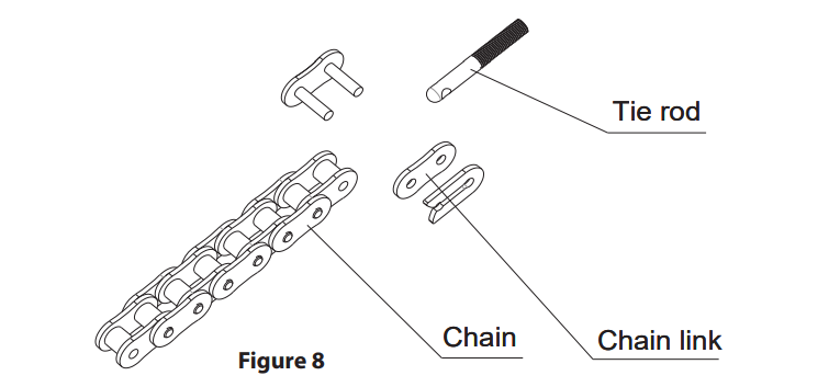
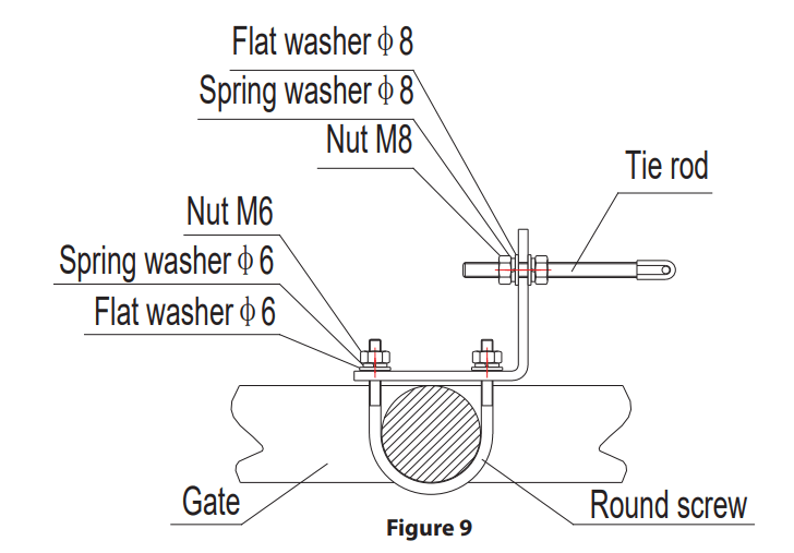
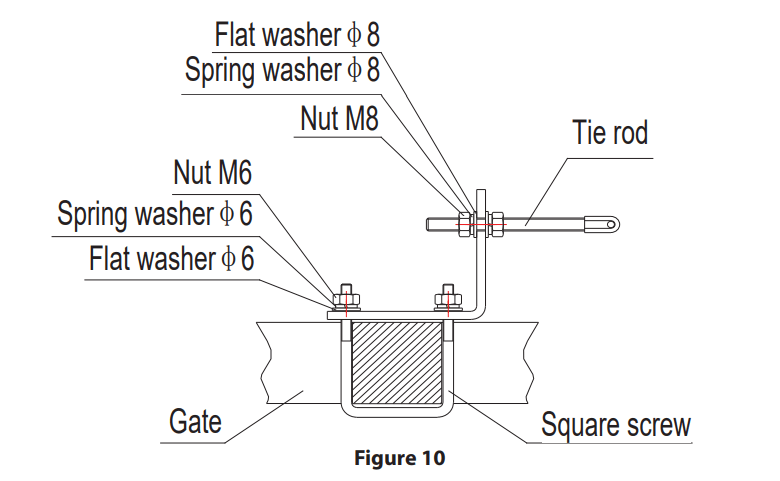
Close the gate; connect the tie rod with chain through chain link; fasten the tie rod to the door connecting plate with washers and nuts as shown in Figure 8. If necessary, the elasticity of the chain can be adjusted through the tie rod at both ends as shown in Figure 9 and 10. If necessary, the chain can be shortened. If it needs to be lengthened, make sure to use the same type of chain.
If door frame is round, please use the round screw as shown in Figure 9:
If door frame is square, please use the square screw as shown in Figure 10
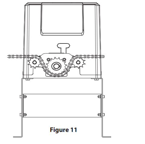
Installation of the chain between the small and big sprocket as shown in Figure 11
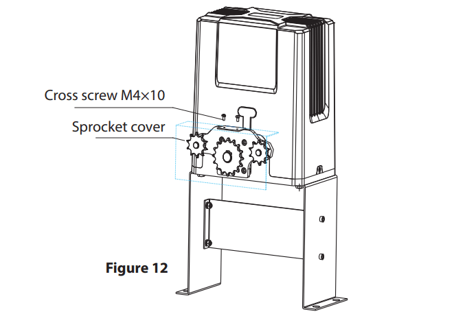
Installation of the sprocket cover as shown in Figure 12
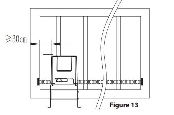
The distance between main engine and chain ends should be at least 30CM, as shown in Figure 13.
Warnings
Limit switch adjustment
Use the manual release key to unlock gate opener and manually move the gate to the predetermined position; fix the magnetic limit switch block and close the clutch; testing run after power on, slightly adjust the position of the magnetic limit switch block until the gate reaches the desired open and close limit location.
Installation position of magnetic limit switch as shown in Figure 14 and Figure 15
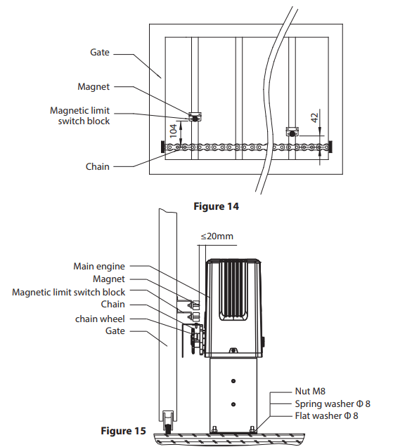
Note: The default setting is right side mounting. (According to actual situation, please refer to the “Note” of section 4.3.5.1 and 4.3.5.2 “Adjustment and operation” to adjust.)
Standard control board

Wiring instruction:
X5 Terminal
24VDC Power supply for fittings +24VDC (Electric current ≤50mA);
GND Power ground;
I.R Photocell input (N.C.);
CLLM Close limit switch;
COM Limit switch common terminal;
OPLM Open limit switch
X7 Terminal
COM Control button common terminal;
STP Stop control button (N.O.);
CLS Gate close control button (N.O.);
OPN Gate open control button (N.O.).
DIP Switch
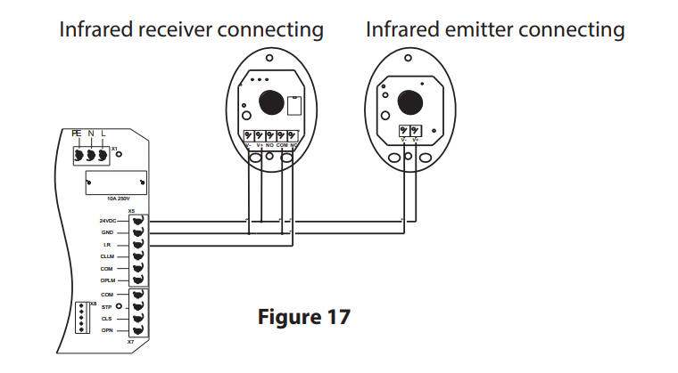
Infrared Connection
Infrared photocell function: In the closing process, when infrared ray of the photocell is covered by people or objects during its detection range, the gate will open immediately for security protection. The distance between photocell receiver and photocell emitter should be more than 2 meters, otherwise will affect the induction of the photocell. If connect the infrared photocell, please remove the short connection between I.R and GND on the X5 terminal.
Adjustment and operation
Remote control operation
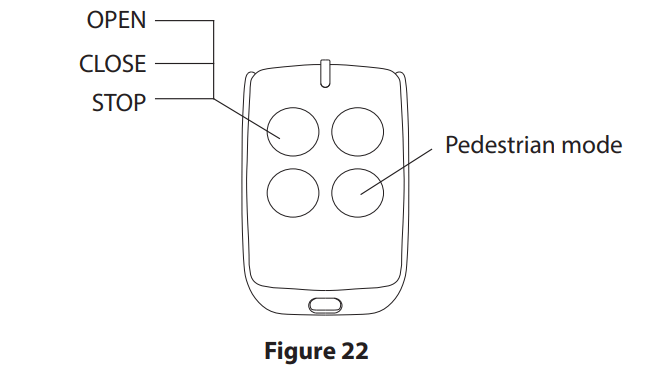
Single button mode remote control: OPEN/CLOSE/STOP of main engine are controlled by one button circularly on the remote control.
Add extra remote control (remote control learning):
Remove the main engine housing, then take out the upper cover of the control box, press the learning button AN1 on the control board, and indicator light LED2 will ash. Press the button that to be learned on the remote control once, The LED2 will be off. Press the same button on the remote control twice, the LED2 will flash several times and be off; remote control learning complete. A maximum of 25 remote controls can be learned.
Delete remote control:
To delete remote control that have been learned: press and hold the learning button AN1, the indicator light LED2 will be on; Then release it until LED2 is off. After the steps, all the matched remote controls will be deleted.
Note: To disengage gate opener, move the gate to the middle position, then close the clutch and press the open button of external button switch to open the gate. If the gate opening direction is wrong, you can change the direction through the toggle switch SW1 on the control board or exchange the motor phase-sequence lines U and W. If the opening or closing limit is wrong, please exchange limit switch lines CLLM and OPLM on the control board.
Intelligent control board
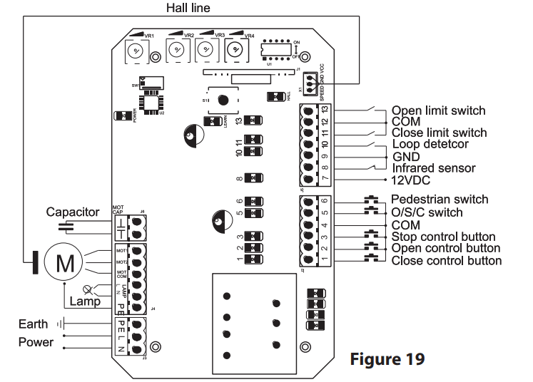
Wiring instruction:
J2 Terminal (For the convenience of wiring, this terminal is accompanied with failure diagnosis light)
Function adjustment
Functional parameters of the control board equipped with microprocessor can be adjusted through potentiometer and dip switch, so as to meet di erent installation requirements.
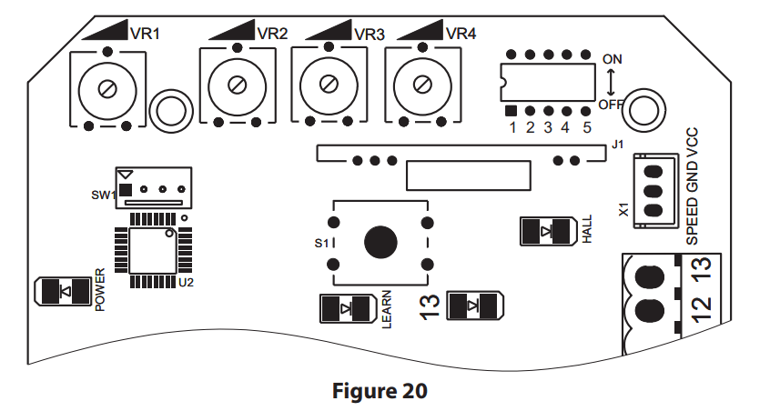
Adjusting knob
VR1: When meet obstacle reverse function is enabled (DIP switch 5 on OFF position and the motor assembled with the hall line). This knob is used for sensitivity adjustment of meeting obstacle.
Clockwise rotation to reduce sensitivity of obstacle, counter-clockwise rotation to increase sensitivity of obstacle. When meet obstacle reverse function is disabled (DIP switch 5 on ON position).
This knob is used for motor working total time adjustment. Clockwise rotation to increase, counter-clockwise rotation to reduce. The total time can be set to 10 seconds as minimum and 90 seconds as maximum.
VR2: For brake force adjustment in limit position. Clockwise rotation to increase, counter-clockwise rotation to reduce. Rotate to minimum to cancel brake function in place.
VR3: For slow stop width adjustment. Clockwise rotation to increase, counterclockwise rotation to reduce. Rotate to the minimum to cancel the slow stop function.
VR4: For motor output force adjustment to keep safe usage. Clockwise rotation to increase, counter-clockwise rotation to reduce.
Note: The default setting is VR1, VR2, VR3, VR4 are the maximum value, and the user can adjust according to the actual requirement.
Warning: The motor output force cannot be set too large, just to be able to drive the gate.
Dip switch
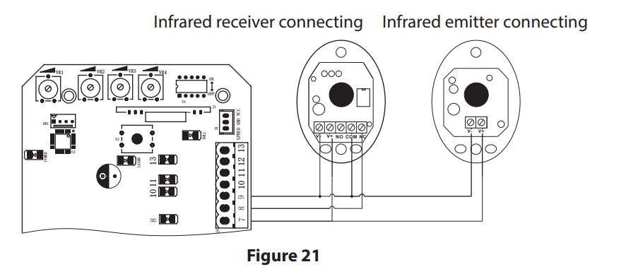
Infrared connection
Infrared photocell function: In the closing process, when infrared ray of the photocell is covered by people or objects during its detection range, the gate will open immediately for security protection. The distance between photocell receiver and photocell emitter should be more than 2 meters, otherwise will affect the induction of the photocell. If connect the infrared photocell, please remove the short connection between 8 and 9 on the J5 terminal.
Adjustment and operation
Remote control operation
Single button mode remote control: OPEN/CLOSE/STOP of main engine are controlled by one button circularly on the remote control.
Add extra remote control (remote control learning):
Remove the main engine housing, then take out the upper cover of the control box, press and hold the learning button S1 for 2 seconds, then the indicator light LEARN will be on; press the button that to be learned on the remote control twice, the LEARN will flash several times and be off; remote control learning complete. A maximum of 40 remote controls can be learned.
Delete remote control:
To delete remote control that have been learned; press and hold the learning button S1, the indicator light LEARN will be on; Then release it until LEARN is off. After the steps, all the matched remote controls will be deleted.
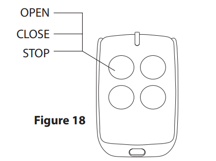
The fourth button on the remote control is for pedestrian mode, press the button while the door is closed, it will open for 1 meter which is for pedestrian only
Note: To disengage gate opener, move the gate to the middle position, then close the clutch and press the open button of external button switch to open the gate. If the gate opening direction is wrong, you can exchange the motor phase-sequence lines MOT2 and MOT1. If the opening or closing limit is wrong, please exchange limit switch lines which are connected to the corresponding terminal 11 and 13 on the control board.
Check whether the gate operates normally every month.
For the sake of safety, each gate is suggested to be equipped with infrared protector, and regular inspection is required. Before installation and operation of the gate opener, please read all instructions carefully. Our company has the right to change the instruction without prior notice.
| Problems | Possible Reasons | Solutions |
| The gate cannot open or close normally, and LED does not light. |
|
|
| The gate can open but cannot close. |
|
|
| Remote control doesn’t work. |
|
|
| Press OPEN, CLOSE button, the gate is not moving, motor has noise. |
|
|
| Not stop at the limit position when opening / closing. |
The limit direction is wrong. The mounting of magnetic limit switch with problem. |
Check whether the limit switch wiring is consistent with the actual direction of operation. Check whether the distance between magnetic limit switch and motor, and the height of the magnetic limit switch can reach up the mounting requirement. |
| Leakage switch tripped | Power supply line short circuit or motor line short circuit. | Check wiring. |
| Remote control working distance is too short. | Signal is blocked. | Connect external receiver antenna, 1.5 meters above ground. |
| The gate moves to the middle position to stop or reverse. |
|
|
| Gate opens automatically | Automatic close function has been turned on but with incorrect opening direction. | Please refer to the attentions under 4.3.5.1 and 4.3.5.2 to change the opening direction |
Technical Specs:
