
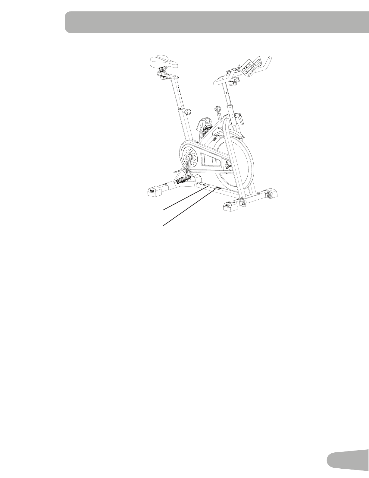
ASSEMBLY MANUAL / OWNER’S MANUAL ASSEMBLY MANUAL / OWNER’S MANUAL
TM
700IC

2
Important Safety Instructions 3
Safety Warning Labels / Serial Number 5
Specications 6
BeforeAssembly 6
Parts 7
Hardware 8
Tools 8
Assembly 9
Installing Shoe Clips (Cleats) 14
LevelingtheMachine 16
MovingandStoringtheMachine 16
Features 17
Emergency Stop 18
Console Features 18
Remote Heart Rate Monitor 19
Shoe Clips (Cleats) 20
Operations 21
Adjustments 21
Locking/Storage 23
Power Up 23
Edit Mode 23
Changing Unit Measures (English Imperial/Metric) 23
Maintenance 24
Replacing the Console Batteries 25
Checking the Belt Tension 25
MaintenanceParts 26
Troubleshooting 27
Nautilus, Inc., 5415 Centerpoint Parkway, Groveport, OH 43125 USA, www.NautilusInc.com - Customer Service: North America
(800)605-3369,[email protected]|Nautilus(Shanghai)FitnessEquipmentsCo,Ltd,Room1701&1702,1018ChangningRoad,
ChangningDistrict,Shanghai,China200042,www.nautilus.cn-862161159668|outsideU.S.www.nautilusinternational.com|
PrintedinChina|©2017Nautilus,Inc.|Schwinn,theSchwinnQualitylogo,Nautilus,JRNYandBowexaretrademarksownedby
or licensed to Nautilus, Inc., which are registered or otherwise protected by common law in the United States and other countries.
Polar® and OwnCode® are registered trademarks of their owner.
ORIGINALMANUAL-ENGLISHVERSIONONLY
TABLE OF CONTENTS
To validate warranty support, keep the original proof of purchase and record the following information:
Serial Number __________________________
Date of Purchase ____________________
To register your product warranty, contact your local distributor.
Ifyouhavequestionsorproblemswithyourproduct,pleasecontactyourlocalSchwinn
™
distributor.
Tondyourlocaldistributor,goto:www.nautilusinternational.comorwww.nautilus.cn

3
IMPORTANT SAFETY INSTRUCTIONS
When using an electrical appliance, basic precautions should always be followed, including the following:
This icon means a potentially hazardous situation which, if not avoided, could result in death or serious
injury.
Obey the following warnings:
Read and understand all warnings on this machine.
Carefully read and understand the Assembly instructions. Read and understand the complete Manual. Keep
the Manual for future reference.
• Keep bystanders and children away from the product you are assembling at all times.
• Donotinstallthebatteriesintothemachineuntilthetimespeciedintheassemblymanual.
• Do not assemble this machine outdoors or in a wet or moist location.
• Makesureassemblyisdoneinanappropriateworkspaceawayfromfoottracandexposuretobystanders.
• Some components of the machine can be heavy or awkward. Use a second person when doing the assembly steps
involving these parts. Do not do steps that involve heavy lifting or awkward movements on your own.
• Set up this machine on a solid, level, horizontal surface.
• Do not try to change the design or functionality of this machine. This could compromise the safety of this machine and
will void the warranty.
• If replacement parts are necessary use only genuine replacement parts and hardware supplied by Nautilus. Failure
to use genuine replacement parts can cause a risk to users, keep the machine from operating correctly and void the
warranty.
• Do not use or put the machine into service until the machine has been fully assembled and inspected for correct
performance in accordance with the Manual.
• ReadandunderstandthecompleteManualsuppliedwiththismachinebeforerstuse.KeeptheManualforfuture
reference.
• Doallassemblystepsinthesequencegiven.Incorrectassemblycanleadtoinjuryorincorrectfunction.
• SAVE THESE INSTRUCTIONS.
Before using this equipment, obey the following warnings:
Read and understand the complete Manual. Keep the Manual for future reference.
Read and understand all warnings on this machine. If at any time the Warning stickers become loose,
unreadable or dislodged, contact your local distributor for replacement stickers.
• Children must not be let on or near to this machine. Moving parts and other features of the machine can be dangerous
to children.
• Not intended for use by anyone under 14 years of age.
• Consultaphysicianbeforeyoustartanexerciseprogram.Stopexercisingifyoufeelpainortightnessinyour
chest, become short of breath, or feel faint. Contact your doctor before you use the machine again. Use the values
calculated or measured by the machine’s computer for reference purposes only.
• Beforeeachuse,examinethismachineforloosepartsorsignsofwear.Donotuseiffoundinthiscondition.Monitor
the Seat, Pedals and Crank Arms closely. Contact your local distributor for repair information.
• Maximumuserweightlimit:136kg(300lb).Donotuseifyouareoverthisweight.
• This machine is for home use only.Do not place or use the machine in a commercial or institutional setting. This
includesgyms,corporations,workplaces,clubs,tnesscentersandanypublicorprivateentitythathasamachinefor
usebyitsmembers,customers,employeesoraliates.
• Donotwearlooseclothingorjewelry.Thismachinecontainsmovingparts.Donotputngersorotherobjectsinto
movingpartsoftheexerciseequipment.

4
• Set up and operate this machine on a solid, level, horizontal surface.
• MakethePedalsstablebeforeyousteponthem.Usecautionwhenyousteponandothemachine.
• Disconnect all power before servicing this machine.
• Do not operate this machine outdoors or in moist or wet locations. Keep the Pedals clean and dry.
• Keepatleast0.6m(24in)alongthesideusedtoaccessthemachineandtotherearofthemachineclear.Thisisthe
recommended safe distance for access, passage and emergency dismounts from the machine. Keep third parties out
of this space when machine is in use.
• Donotoverexertyourselfduringexercise.Operatethemachineinthemannerdescribedinthismanual.
• Perform all regular and periodic maintenance procedures recommended in the Owner’s Manual.
• Do not drop or put objects into any opening of the machine.
• Correctly adjust and safely engage all Positional Adjustment Devices. Make sure that the Adjustment Devices do not
hit the user.
• Exerciseonthismachinerequirescoordinationandbalance.Besuretoanticipatethatchangesinspeedand
resistance level can occur during workouts, and be attentive in order to avoid loss of balance and possible injury.
• Keep batteries away from heat source and hot surfaces.
• Donotmixoldandnewbatteries.Removeexhaustedbatteriesanddisposeofthemsafely.
• Donotmixalkaline,standard(carbon-zinc),orrechargeable(Ni-Cd,Ni-MH,etc)batteries.
• Do not short-circuit the supply terminals on the batteries.
• This appliance is not intended for use by persons with reduced physical, sensory or mental capabilities, or lack of
knowledge, unless they have been given supervision or instruction concerning use of the appliance by a person
responsible for their safety. Keep children under the age of 14 away from this machine.
• Sincethismachineoperateswithaxedgear,donotback,orreverse,pedal.DoingsomayloosenthePedals,which
could result in damage to the machine and/or injury to the user. Never operate this machine with loose Pedals.
• Reduce the pace to slow the Pedals to a stop. Do not dismount the bike until the Pedals have come to a complete
stop. Be aware that the moving Pedals can strike the backs of the legs.
• Children should be supervised to ensure that they do not play with the appliance.
• SAVE THESE INSTRUCTIONS.
5
SAFETY WARNING LABELS AND SERIAL NUMBER
Product specication
Serial number
This product complies with the European Radio Equipment Directive 2014/53/EU.
6
SPECIFICATIONS
Before Assembly
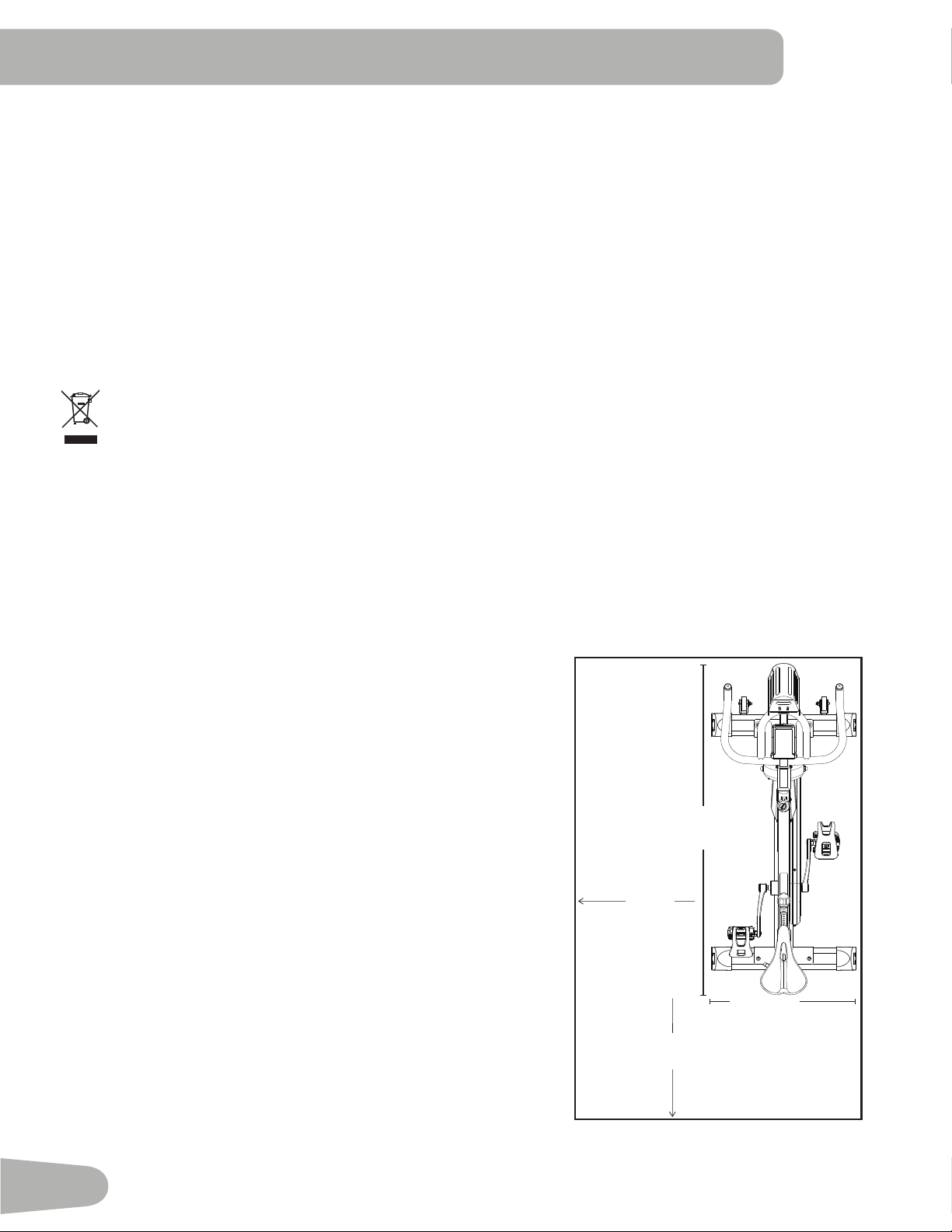
Select the area where you are going to set up and operate your machine. For safe operation, the location must be on a
hard,levelsurface.Allowaworkoutareaofaminimum1.9mx1.2m(73”x45”).
Basic Assembly Tips
Follow these basic points when you assemble your machine:
• Readandunderstandthe“ImportantSafetyInstructions”
before assembly.
• Collect all the pieces necessary for each assembly step.
• Using the recommended wrenches, turn the bolts and nuts
to the right (clockwise) to tighten, and the left (counter-
clockwise) to loosen, unless instructed otherwise.
• When attaching 2 pieces, carefully lift and look through the
bolt holes to help insert the bolt through the holes.
• Theassemblyrequires2people.
Maximum User Weight: 136kg(300lb)
Total Surface Area (footprint) of equipment:6667.4cm2
Machine Weight: 46kg(101lb)
Dimensions: 123.7cmx53.9cmx126.6cm(48.7”x21.2”x49.8”)
Power Requirements: 2 AA Batteries (SUM3)
Operating Voltage: 3VDC
Specications
DO NOT dispose of this product as refuse. This product is to be recycled. For proper disposal of this product,
please follow the prescribed methods at an approved waste center.
0.6 m
(24”)
1.2 m (45”)
1.9 m
(73”)
0.6 m
(24”)
123.7 cm
(48.7”)
53.9 cm
(21.2”)
7
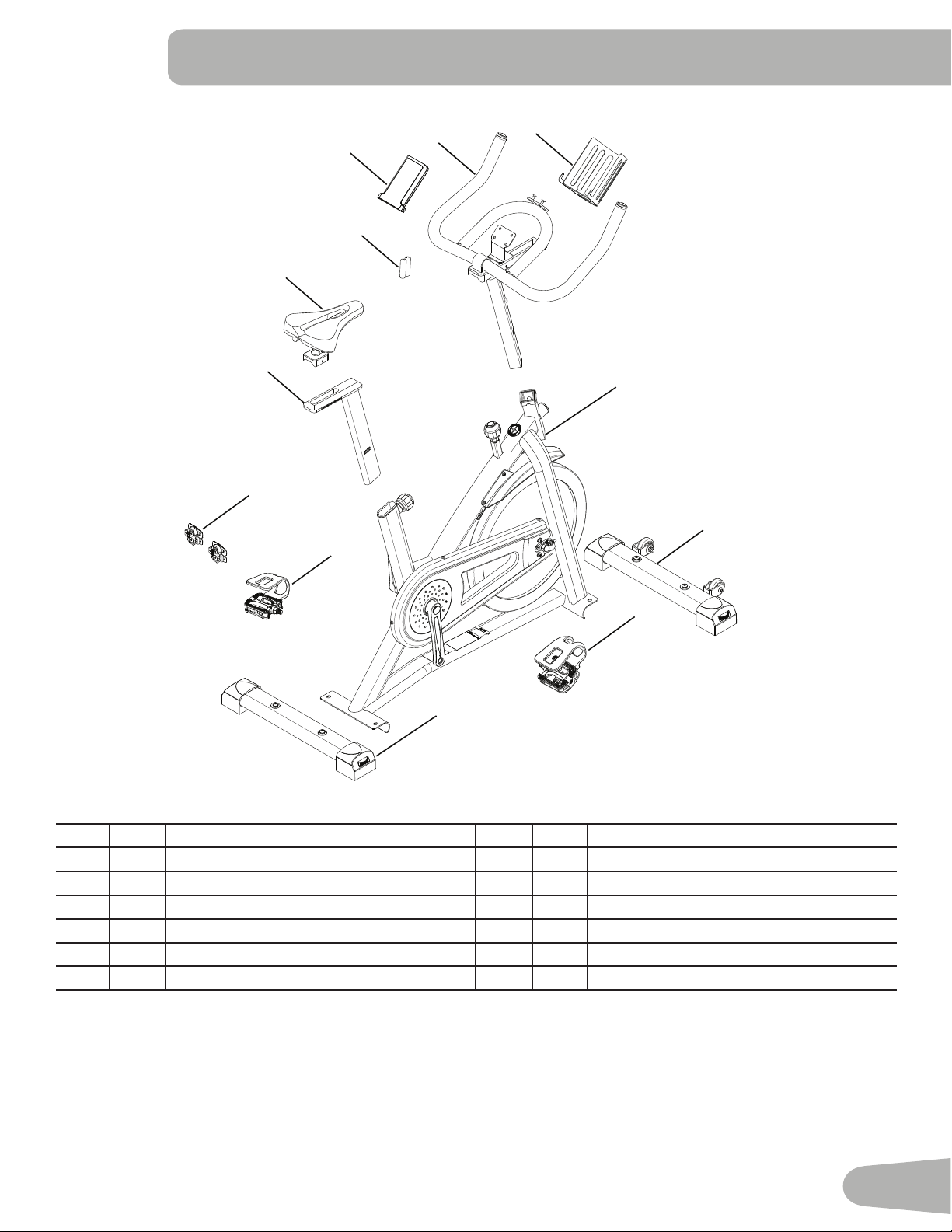
Item Qty Description Item Qty Description
1 1 Main Frame 7 1 Pedal, Right
2 1 Stabilizer, Front 8 1 Pedal, Left
3 1 Stabilizer, Rear 9 1 Water Bottle Holder
4 1 Seat Post 10 1 Console
5 1 Seat 11 2 AA Batteries (SUM3)
6 1 Handlebar 12 2 Shoe Clips (Cleats)
PARTS
1
2
3
7
8
5
4
10
6
9
12
11
8
Tools
Included
HARDWARE / TOOLS
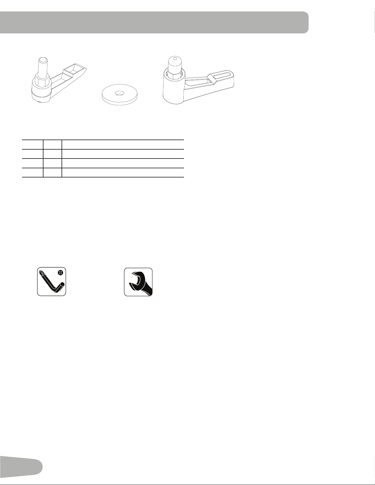
Item Qty Description
A 2 Adjustment Handle, Handlebar / Seat
B 2 Flat Washer, M10 Wide
C 1 Adjustment Handle, Handlebar Post
A B C
15 mm
17 mm
#2
6mm
9
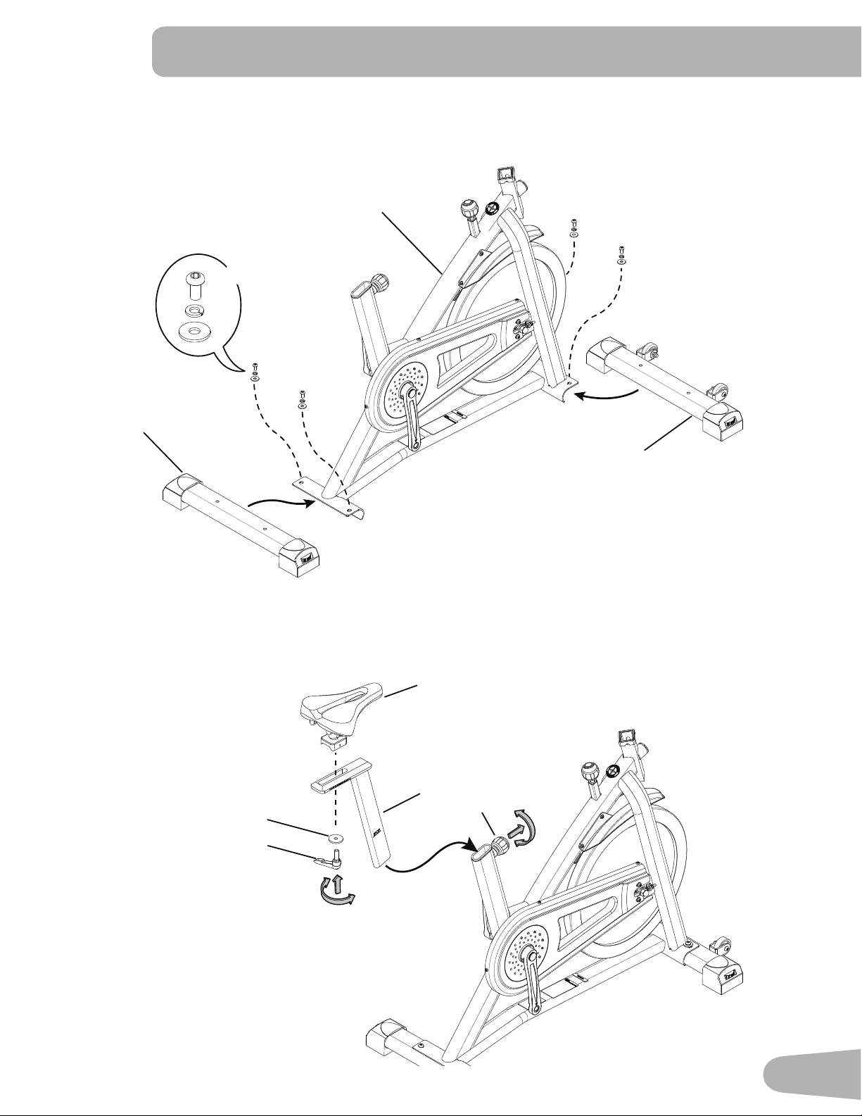
1. Attach Stabilizers to Main Frame
Note: The hardware (*) is pre-installed and not in the Hardware Bag. If a tube is pre-installed in the stabilizer bracket,
remove and set it safely aside.
ASSEMBLY
2. Attach Seat to Seat Post and Frame
NOTICE: Make sure the adjustment knob (4a) engages the holes in the Seat Post.
1
2
3
*
*
*
X4
5
4
A
B
4a
10
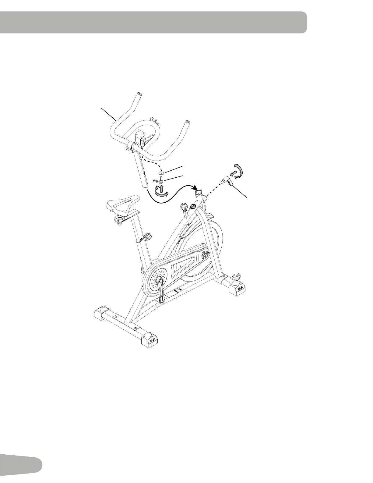
3. Install Handlebar Assembly on Frame
NOTICE: Make sure the Adjustment Handle (C) engages the holes in the Handlebar Post.
6
B
A
C
11
8
7
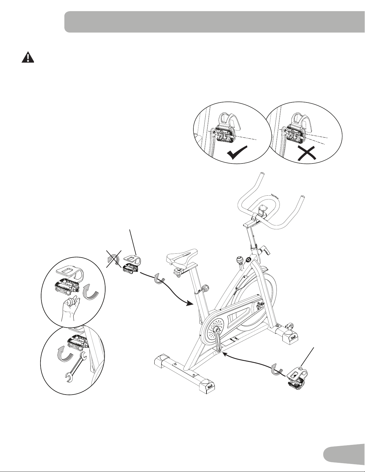
4. Attach Pedals to Frame Assembly
If the threads strip due to improper installation, then the Pedals can disengage from the bike and/or break
while under usage, which can result in serious injury to the user.
Note: The Left Pedal is reverse-threaded. Be sure to attach Pedals on the proper side of the Bike. Orientation is based
fromaseatedpositiononthebike.TheLeftPedalhasan“L”,theRightPedalan“R”.
NOTICE: The Pedals MUST be installed straight into the Crank
Arms by hand or the threads that secure the Pedals may strip.
Start the Pedal by hand. If you feel resistance and the Pedal
does not turn smoothly into the Crank Arm, make sure that the
threads are aligned correctly. Be sure that the Pedal is going on
straight into the Crank Arm. If the Pedal is not in-line with the
opening, remove the Pedal and start again.
With the Pedal started by several hand turns into the Crank Arm, fully tighten it with the 15 mm Wrench.
Confirm that the Pedal is fully tightened with the Wrench.
Repeat with the other Pedal.
12
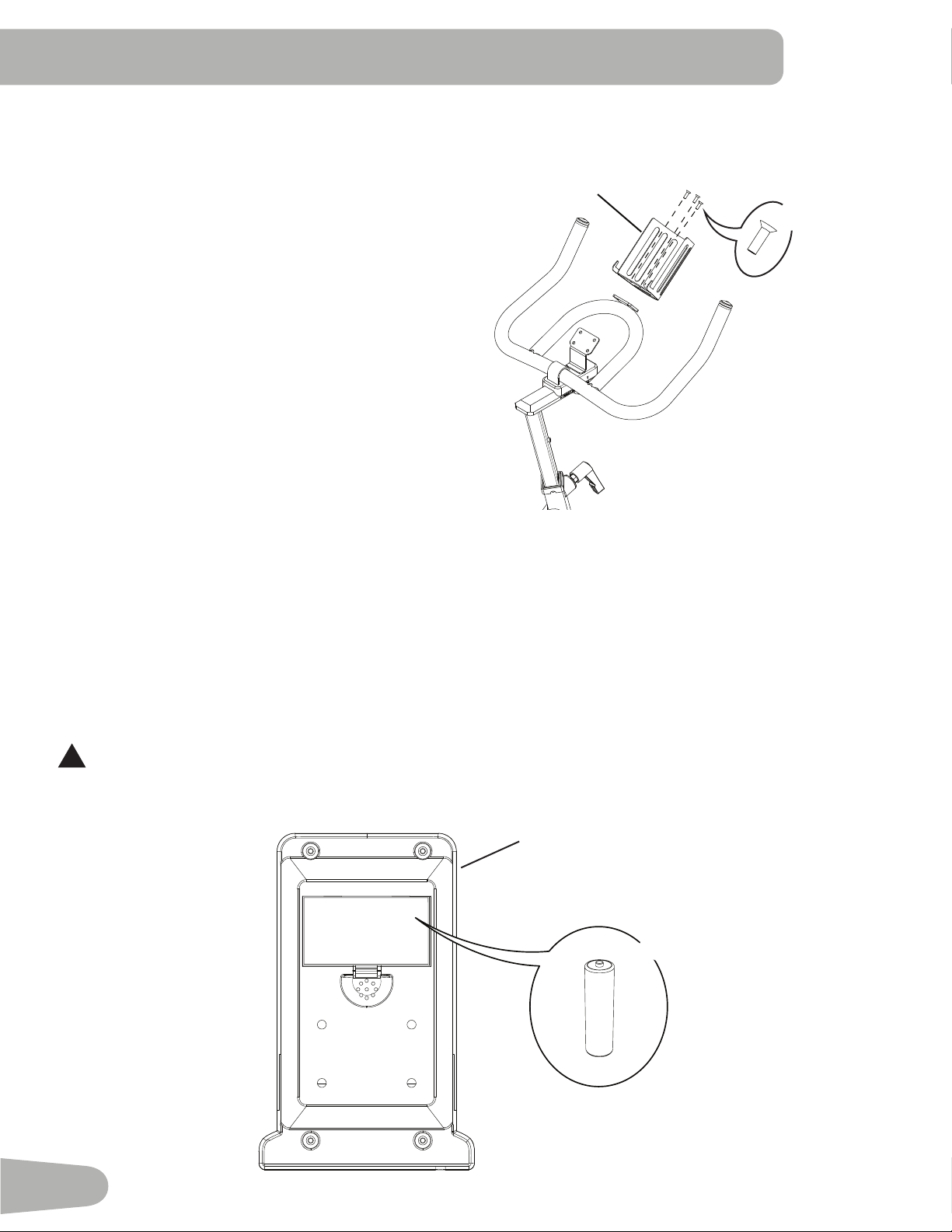
6. Install Batteries in Console
Note: The console uses AA size batteries (SUM3). Make sure that the batteries point in the direction of the +/– indicators in
the battery bay.
!
Do not mix old and new batteries.
Do not mix alkaline, standard (carbon-zinc), or rechargeable (Ni-Cd, Ni-MH, etc) batteries.
+
-
X2
10
11
5. Attach Water Bottle Holder to Handlebar
Note: The hardware (*) is pre-installed and not in the Hardware Bag.
9
*
X3
13
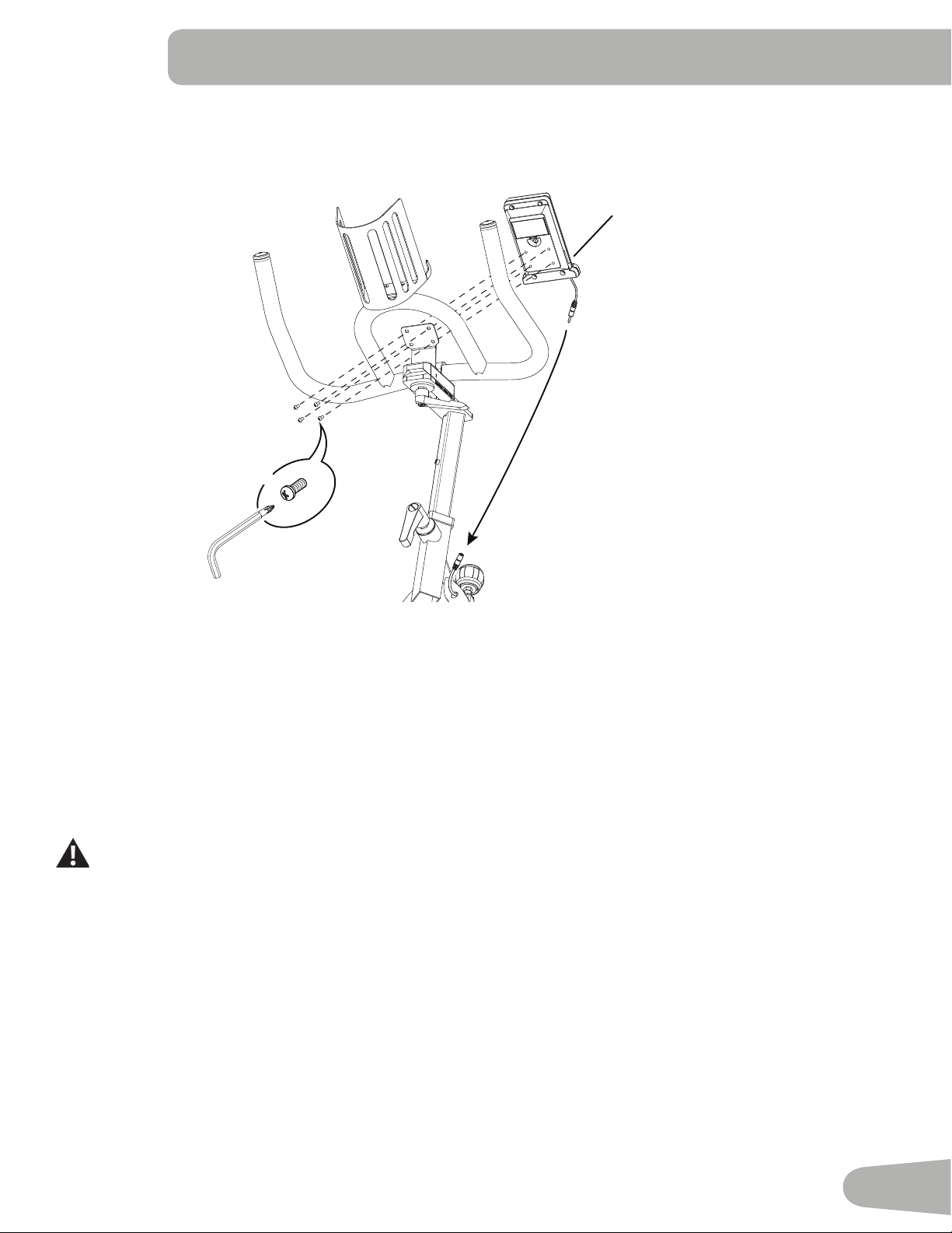
7. Connect and Attach the Console
NOTICE: Remove the pre-installed screws(*) from the back of the Console before you connect the cable. Do not crimp the
cable.
10
X4
#2
*
8. Final Inspection
Inspect your machine to ensure that all hardware is tight and components are properly assembled.
Be sure to record the serial number in the field provided at the front of this manual.
Do not use or put the machine into service until the machine has been fully assembled and inspected for
correct performance in accordance with the Owner’s Manual.
14
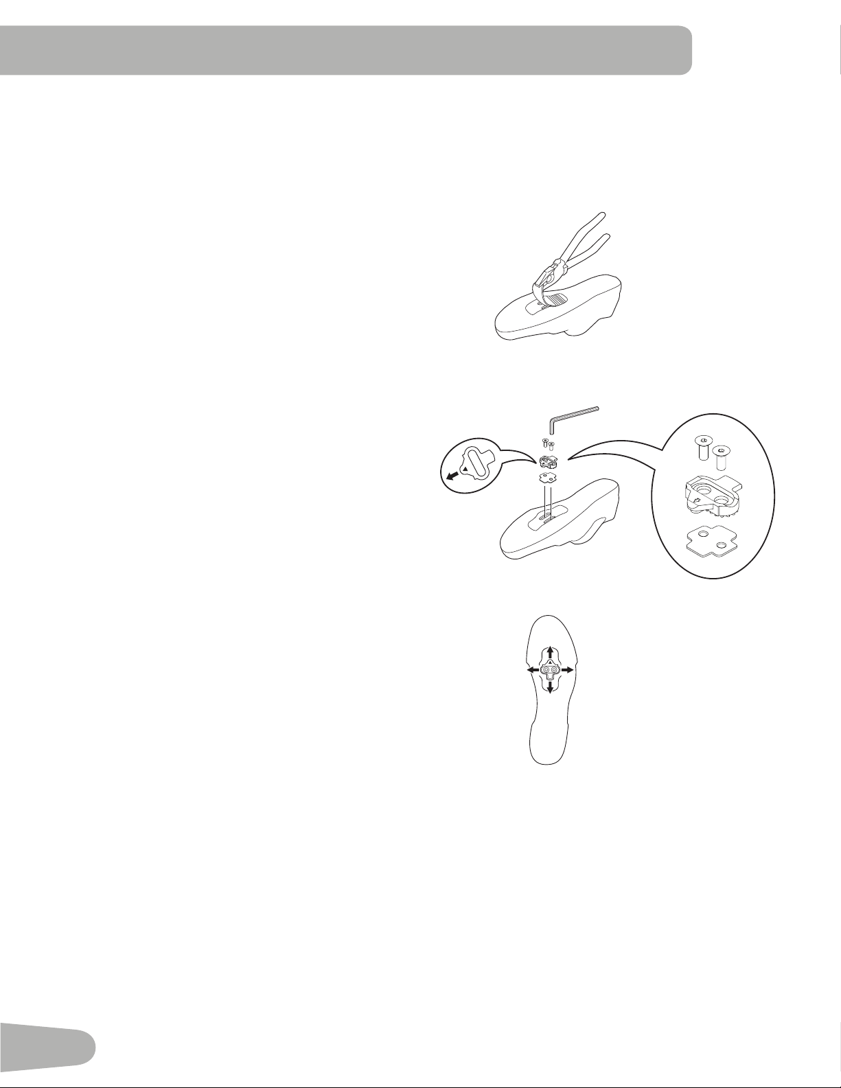
Installing Shoe Clips (Cleats) on Cycling Shoes (optional accessory)
Shoe Clips (Cleats) – later version
Note: TheshoecleatstboththerightandleftPedals.
Tools needed:pliers,4mmhexkey
1. Withapairofpliers,pullotherubbercovertoexpose
the cleat mounting holes on the bottom of the cycling
shoe.
Note: This step may not be necessary, depending on the
type of shoe.
2. From the bottom of the shoe, put the anti-skid sheet in
position over the cleat holes and then a cleat. Be sure
the single arrow on the cleat points toward the toe of the
shoe. Tighten the cleat mounting bolts (2.5 N·m).
3. The cleat has an adjustment range of 20mm front to
back and 5mm left to right. Practice engaging with the
Pedal and releasing, one shoe at a time. Readjust to
determine the best cleat position.
4. Usinga4mmhexkey,fullytightenthecleatmounting
bolts(5–6N·m).
4 mm
15
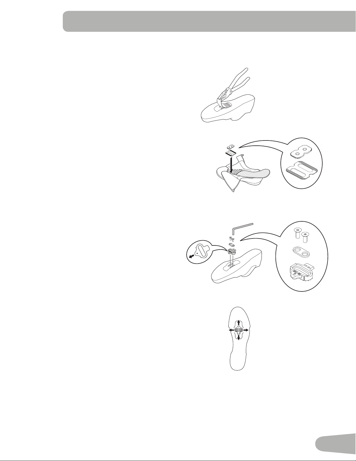
Shoe Clips (Cleats) – earlier version
Note: TheshoecleatstboththerightandleftPedals.
Tools needed:pliers,4mmhexkey
1. Withapairofpliers,pullotherubbercovertoexpose
the cleat mounting holes on the bottom of the cycling
shoe.
Note: This step may not be necessary, depending on the
type of shoe.
2. Remove the sockliner and put the cleat nut in position
over the oval holes inside the shoe.
Note: This step may not be necessary, depending on the
type of shoe.
3. From the bottom of the shoe, put a cleat in position over
the cleat holes and then a cleat adapter. Be sure the
single arrow on the cleat points toward the toe of the
shoe. Tighten the cleat mounting bolts (2.5 N·m).
4. The cleat has an adjustment range of 20mm front to
back and 5mm left to right. Practice engaging with the
Pedal and releasing, one shoe at a time. Readjust to
determine the best cleat position.
5. Usinga4mmhexkey,fullytightenthecleatmounting
bolts(5–6N·m).
4 mm
SR-168
16
BEFORE YOU START
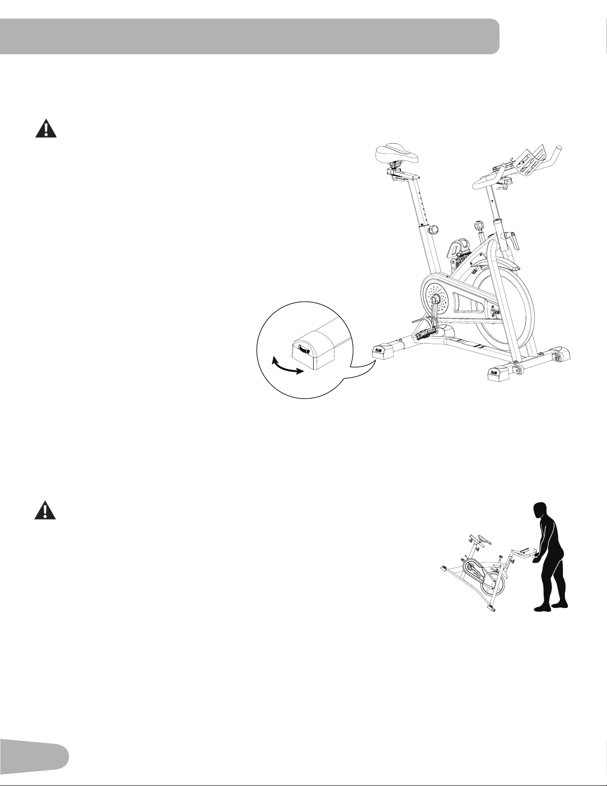
Leveling the Machine
The machine needs to be leveled if your workout area is uneven. Levelers are found on each side of the stabilizers. Lift
thestabilizerslightlytotaketheweightotheadjuster,thenturntheknobtoadjustthestabilizerfoot.
Do not adjust the levelers to such a height that they detach or unscrew from the machine. Injury to you or
damage to the machine can occur.
Makesurethemachineislevelandstablebeforeyouexercise.
Moving and Storing the Machine
To move the bike, carefully pull the Handlebars toward you while pushing the front of the bike downward. Push the bike to
the desired location.
NOTICE:Becarefulwhenyoumovethemachine.Abruptmotionscanaectthecomputeroperation.
For safe storage of the machine, remove the batteries. Place the machine in a
secure location away from children and pets.
17
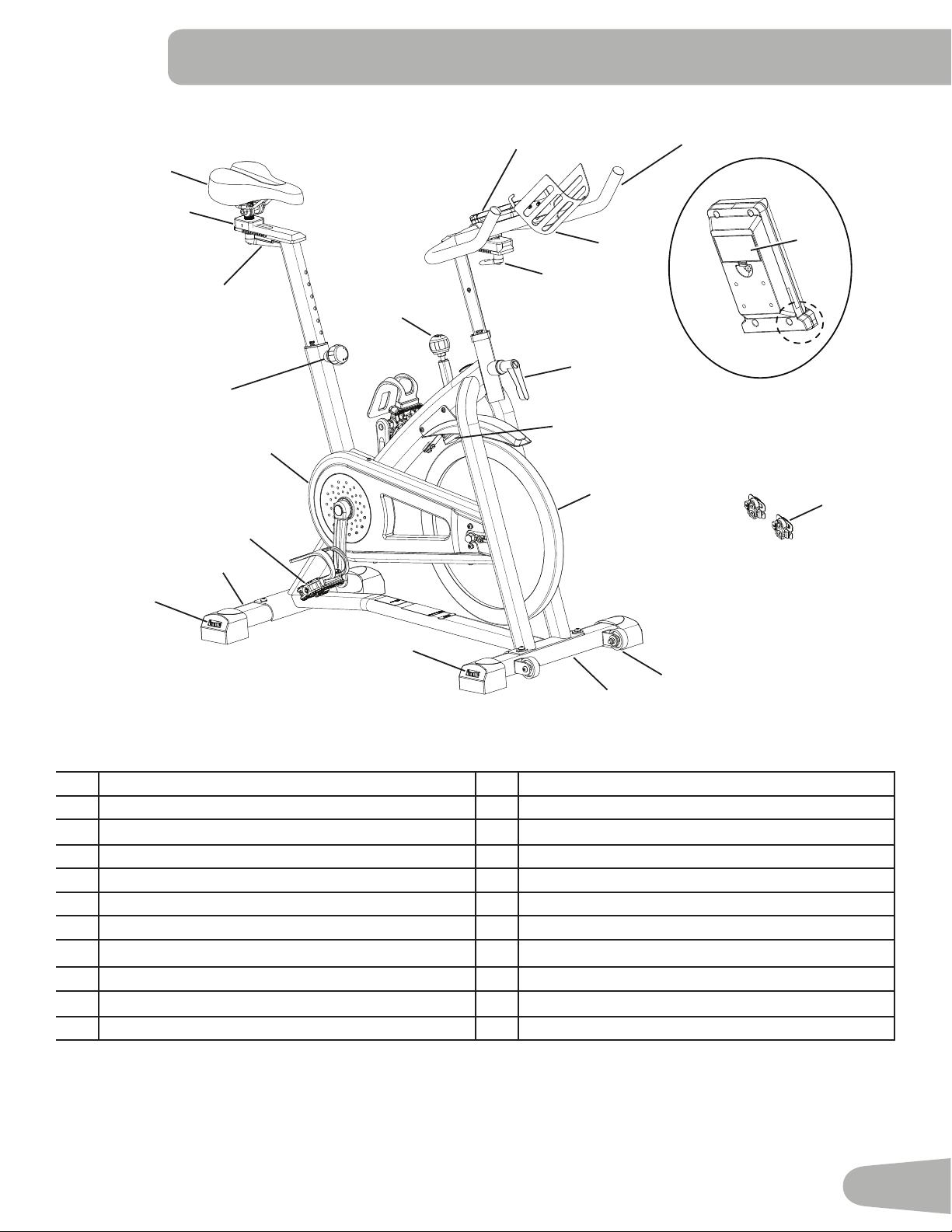
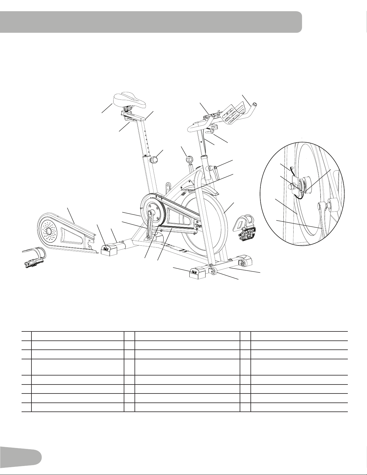
A Console L Pedal w/Foot Restraint
B Handlebar Assembly M Flywheel
C Adjustment Handle, Handlebar Slider N Brake Assembly
D Adjustment Handle, Handlebar Post O Cover, Drive Belt
E Brake/Resistance Adjustment Knob P Front Stabilizer
F Seat Q Transport Wheel
G Seat Slider R Battery Bay
H Adjustment Handle, Seat Slider S Telemetry Heart Rate (HR) Receiver
I Adjustment Handle, Seat Post T Water Bottle Holder
J Rear Stabilizer U Shoe Clips (Cleats)
K Leveler
FEATURES
WARNING! Use the values calculated or measured by the machine’s computer for reference purposes only. The
heart rate displayed is an approximation and should be used for reference only. Over exercising may result in
serious injury or death. If you feel faint stop exercising immediately.
M
A
B
C
D
E
F
G
H
I
J
K
L
N
O
P
Q
K
T
U
R
S
18
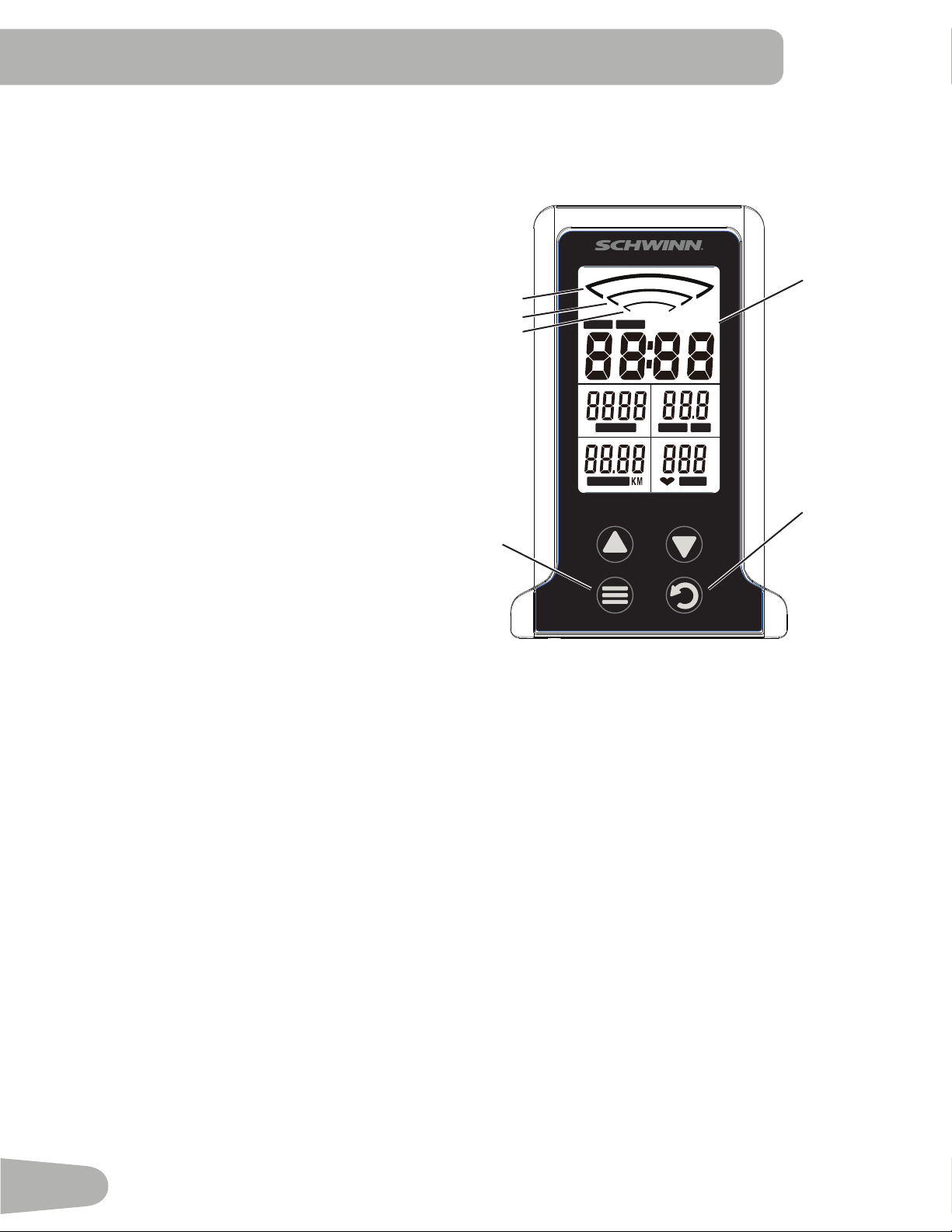
Console Features
The Console provides information about your
workout on the display screens.
Keypad Functions
MODE button- Selects functions to edit values (set
workout goal).
RESET button- Push to reset TIME, DISTANCE,
CALORIES to zero. Push and hold 3 seconds to
restart the console.
- Push to increase the value.
- Push to decrease the value.
The console will beep when a button is pushed.
Program Data Display
Average RPM Range
The RPM range display shows the current average revolutions per minute (RPM). As the RPM increases, a larger
indicatorislittoshowthehigherRPMrange.Therangesare:1-29,30-59,and60-120.
TIME
TheTIMEdisplayeldshowsthetimefromstarttonishofworkout.Tosetatimegoalfortheworkout,pushMODEuntil
theTIMEeldblinks.Usethearrowkeystoadjustthetimegoal(minutes).Duringtheworkout,thedisplayshowsthe
remaining time. When it reaches zero, the console will sound an alert.
Themaximumtimeis99minutesand59seconds.
CALORIES
TheCALORIESdisplayeldshowstheestimatedtotalcaloriesfromstarttonishofworkout.Tosetacaloriesgoalforthe
workout,pushMODEuntiltheCALORIESeldblinks.Usethearrowkeystoadjustthecalories.Duringtheworkout,the
display shows the remaining calories. When it reaches zero, the console will sound an alert.
Themaximumcaloriesvalueis999.9Kcal.
SPEED / RPM
TheSPEED/RPMdisplayeldshowsthecurrentrevolutionsperminute(RPM)orcalculatedspeedoftheuser.InSCAN
mode, the RPM and SPEED are displayed alternately.
ThemaximumSPEEDis99.9km/h.
Emergency Stop
To stop the pedals immediately, push down hard on the Brake/Resistance Adjustment Knob.
TIME SCAN
SPEED RPMCALORIES
DISTANCE PULSE
RESET
MODE
Data Display
Average RPM
<120
<60
<30

19
DISTANCE
TheDISTANCEdisplayeldshowsthedistancefromstarttonishofworkout.Tosetadistancegoalfortheworkout,
pushMODEuntiltheDISTANCEeldblinks.Usethearrowkeystoadjustthedistanceinincrementsof0.50km(or
miles). During the workout, the display shows the remaining distance. When it reaches zero, the console will sound an
alert.
Themaximumdistancevalueis99.99.
The default distance unit is kilometers (K). To switch units between kilometers and miles before a workout, push the Up
and Down arrow keys together and hold 3 seconds. Press any key to save.
HEART RATE (PULSE)
The PULSE display shows the heart rate in beats per minute (BPM) from a telemetric heart rate sensor. Push MODE to
activate the Heart Rate. This display value will be blank if a heart rate signal is not detected. The PULSE range is 40 - 240
BPM.
Consult a physician before you start an exercise program. Stop exercising if you feel pain or tightness in
your chest, become short of breath, or feel faint. Contact your doctor before you use the machine again.
Use the values calculated or measured by the machine’s computer for reference purposes only. The heart
rate displayed on the console is an approximation and should be used for reference only.
Remote Heart Rate Monitor
MonitoringyourHeartRateisoneofthebestprocedurestocontroltheintensityofyourexercise.TheConsolecanread
telemetry HR signals from a Heart Rate Chest Strap Transmitter that operates in the 4.5kHz - 5.5kHz range.
Note: The heart rate chest strap must be an uncoded heart rate strap from Polar Electro or an uncoded POLAR
®
compat-
ible model. (Coded POLAR
®
heart rate straps such as POLAR
®
OwnCode
®
cheststrapswillnotworkwiththisequipment.)
If you have a pacemaker or other implanted electronic device, consult your doctor before using a wireless
chest strap or other telemetric heart rate monitor.
Heart Rate Calculations
Yourmaximumheartrateusuallydecreasesfrom220BeatsPerMinute(BPM)inchildhoodtoapproximately160BPMby
age60.Thisfallinheartrateisusuallylinear,decreasingbyapproximatelyoneBPMforeachyear.Thereisnoindication
thattraininginuencesthedecreaseinmaximumheartrate.Individualsofthesameagecouldhavedierentmaximum
heartrates.Itismoreaccuratetondthisvaluebycompletingastresstestthanbyusinganagerelatedformula.
Yourat-restheartrateisinuencedbyendurancetraining.Thetypicaladulthasanat-restheartrateofapproximately72
BPM, where as highly trained runners may have readings of 40 BPM or lower.
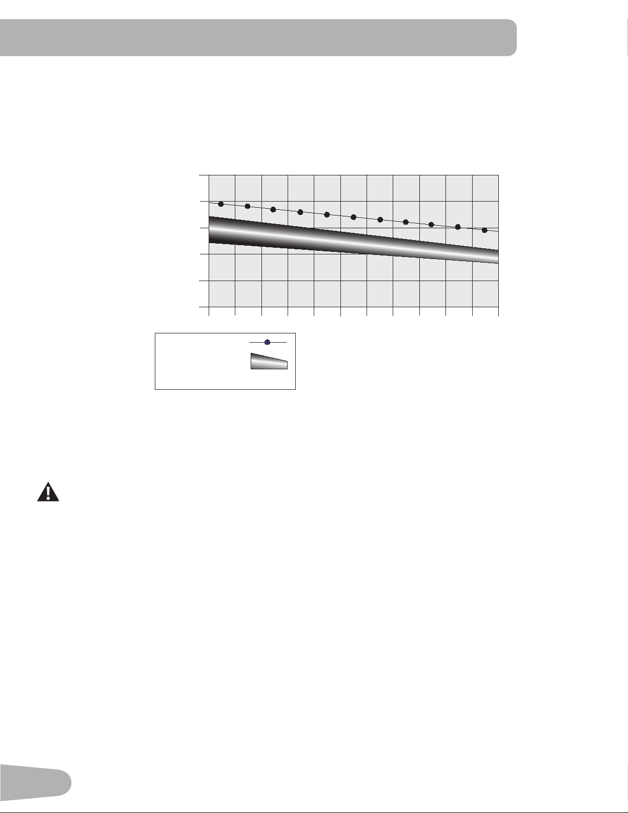
TheHeartRatetableisanestimateofwhatHeartRateZone(HRZ)iseectivetoburnfatandimproveyourcardiovas-
cular system. Physical conditions vary, therefore your individual HRZ could be several beats higher or lower than what is
shown.
Themostecientproceduretoburnfatduringexerciseistostartataslowpaceandgraduallyincreaseyourintensityun-
tilyourheartratereachesbetween60–85%ofyourmaximumheartrate.Continueatthatpace,keepingyourheartrate
in that target zone for over 20 minutes. The longer you maintain your target heart rate, the more fat your body will burn.
20
The graph is a brief guideline, describing the generally suggested target heart rates based on age. As noted above, your
optimal target rate may be higher or lower. Consult your physician for your individual target heart rate zone.
Note:Aswithallexercisesandtnessregimens,alwaysuseyourbestjudgmentwhenyouincreaseyourexercisetime
or intensity.
20-24
FAT-BURNING TARGET HEART RATE
Heart Rate BPM (beats per minute)
Age
25-29
0
50
100
150
200
250
30-34 35-39 40-44 45-49 50-54 55-59 60-64 65-69 70+
196
191
186
181
176
171
166
161
156
151
146
167
162
158
154
150
145
141
137
133
128
126
Maximum Heart Rate
Target Heart Rate Zone
(keep within this range
for optimum fat-burning)
11 8
11 5
11 2
109
106
103
100
97
94
91
88
Shoe Clips (Cleats)
Footpedalsthatareequippedforcyclingshoeswithcleatsprovidesecurefootingontheexercisebike.Theshoecleats
providedtboththerightandleftPedals.
Prior to use, make sure you understand the operation of the engagement / release mechanism for the
pedals and cleats (shoes).
Keep cleats and bindings clear of dirt and debris to ensure engagement and release.
Check the cleats periodically for wear. When the cleats are worn, replace them. Replace the cleat when it
becomes dicult to release, or starts to release with much less eort than when it was in new condition.
PedalsandcleatsareSPDCompatible.Theytanyshoesizewiththecorrectcleatmounts:shoeswith“Standard2-Hole
MTBSPDCleatMounts”(MTBSPD=MountainBikeShimanoPedalingDynamics).
21
OPERATIONS
What to Wear
Wearrubber-soledathleticshoes.Youwillneedtheappropriateclothesforexercisethatallowyoutomovefreely.
How Often Should You Exercise
Consult a physician before you start an exercise program. Stop exercising if you feel pain or tightness in
your chest, become short of breath, or feel faint. Contact your doctor before you use the machine again.
Use the values calculated or measured by the machine’s computer for reference purposes only. The heart
rate displayed is an approximation and should be used for reference purposes only.
• 3 times a week for 20 minutes each day.
• Schedule workouts in advance and try to follow the schedule.
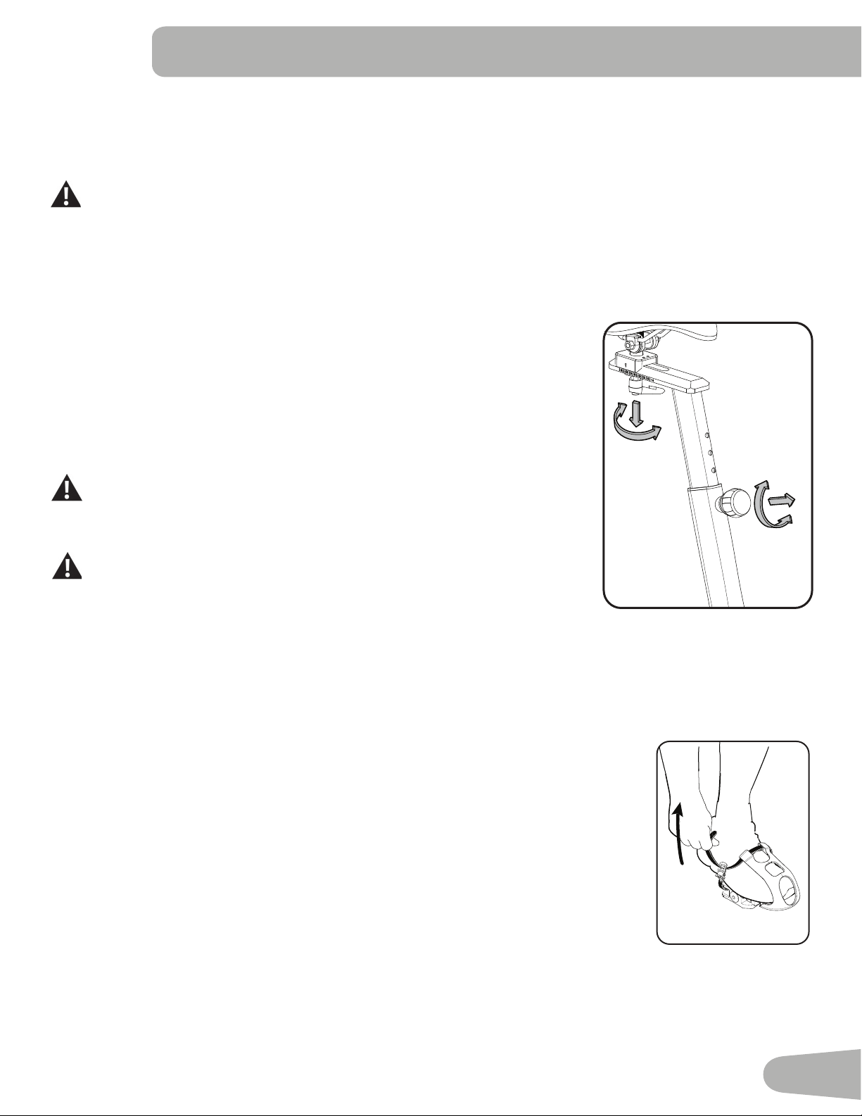
Seat Adjustment
Correctseatplacementencouragesexerciseeciencyandcomfort,whilereducingthe
risk of injury.
1. With a Pedal in the forward position, place the heel of your foot to the lowest part
ofit.Yourlegshouldbebentslightlyattheknee.
2. If your leg is too straight or your foot cannot touch the Pedal, you need to move
the seat downward. If your leg is bent too much, you need to move the seat
upward.
Step o the machine before you adjust the seat.
3. Loosen and pull the Seat Post Adjustment Knob on the Seat Post. Adjust the seat
to the desired height.
Do not lift the Seat post above the “STOP” mark on the Seat Post.
4. Release the Seat Post Adjustment Knob to engage the locking pin. Be sure that
the pin is fully engaged and fully tighten the adjustment knob.
5. To move the seat closer to, or away from the console, loosen the seat adjustment knob. Slide the seat to the desired
position and fully tighten the knob.
Note: If the handle cannot turn due to contact with another part, pull the handle, turn and push it back in to reposition it.
Continue turning as needed.
Foot Position / Pedal Strap Adjustment
Footpedalswithstrapsprovidesecurefootingtotheexercisebike.
1. Put the ball of each foot in the Foot Restraint on the Pedals.
2. Fasten the strap over the shoe.
3. Repeat for the other foot.
BesuretoesandkneespointdirectlyforwardtoensuremaximumPedaleciency.Pedal
strapscanbeleftinpositionforsubsequentworkouts.
22
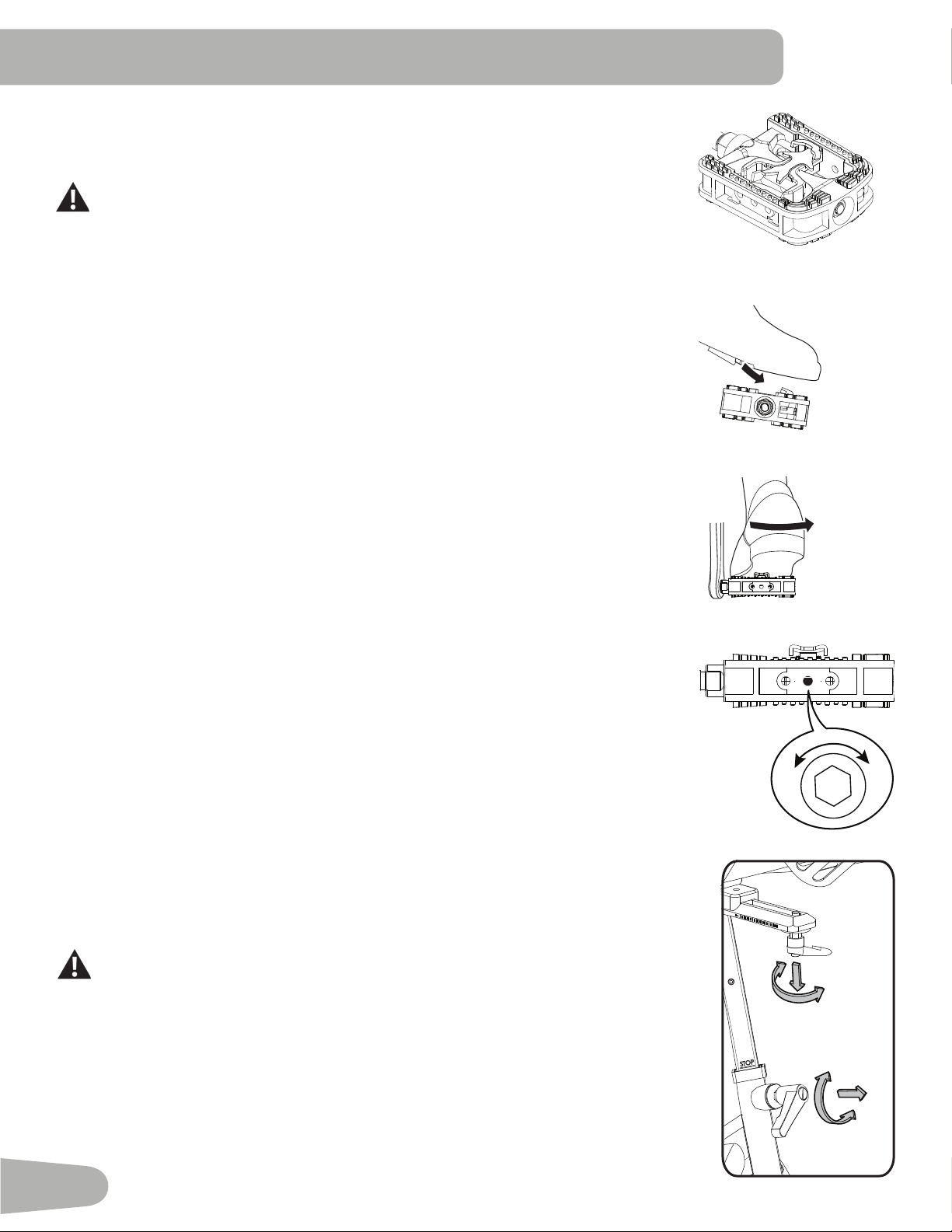
Using the Shoe Clips (Cleats)
Footpedalsthatareequippedforcyclingshoeswithcleatsprovidesecurefootingonthe
exercisebike.BesuretoturnthePedalssothattheFootRestraintisunderthePedal.
Prior to use, make sure you understand the operation of the engagement /
release mechanism for the pedals and cleats (shoes).
Keep cleats and bindings clear of dirt and debris to ensure engagement and
release.
Check the cleats periodically for wear. When the cleats are worn, replace
them. Replace the cleat when it becomes dicult to release, or starts to
release with much less eort than when it was in new condition.
PedalsandcleatsareSPDCompatible.Theytanyshoesizewiththecorrectcleat
mounts:shoeswith“Standard2-HoleMTBSPDCleatMounts”(MTBSPD=Mountain
Bike Shimano Pedaling Dynamics).
1. Be sure that the arrow on top of the Pedal points forward.
2. Push the cleat down and forward to engage the Pedal.
3. Repeat for the other foot.
4. Practice engaging and disengaging from the Pedals before starting your workout.
To disengage (release) the cleats from the pedals, push the heels outward and lift.
Ifthebodyweightofauserisverylow,theusermayhavedicultywithoperationofthe
engagement/release mechanism in the Pedals. It may be necessary to decrease the
retention force of the mechanism. To adjust the retention:
1. Locate the opening in the rear of the Pedal for access to the adjustment bolt. It is
between the 2 screws that attach the Foot Restraint to the Pedal.
2. Usea3mmhexkeytoturntheadjustmentbolt.Todecreasetheretention,turnitleft
(counterclockwise). To increase the retention, turn it right (clockwise).
Handlebar Adjustment
To adjust the handlebar position:
1. Loosen and pull the Handlebar Post Adjustment Knob on the Handlebar Post. Adjust
the Handlebar to the desired height.
Do not lift the Handlebar Post above the “STOP” mark on the Handlebar Post.
2. Tighten the Handlebar Post Adjustment Knob to engage the locking pin. Be sure that
the pin is fully engaged and fully tighten the adjustment knob.
NOTICE: Do not crimp the cables.
3. To move the Handlebar closer to, or away from the console, loosen the Handlebar
Adjustment Knob. Slide the Handlebar to the desired position and fully tighten the
knob.
Note: If the handle cannot turn due to contact with another part, pull the handle, turn and
push it back in to reposition it. Continue turning as needed.
Right Pedal - (Foot restraint
not shown for clarity)
-
+
Engage
Disengage (release)

23
Locking the Flywheel/Storage
Whenthemachineisnotinuse,besuretolocktheFlywheelwiththeBrake/ResistanceAdjustmentKnob.Theywheel
should be locked for storage of the machine.
For safe storage of the machine, remove the batteries and fully tighten the Brake/Resistance Adjustment
Knob to secure the Flywheel. Place the machine in a secure location away from children and pets.
To lock the Flywheel, fully tighten the Brake/Resistance Adjustment Knob to prevent movement of the Flywheel and
Pedals.
Power-Up Mode
The Console will enter Power-Up Mode if any button is pushed, or if it receives a signal from the RPM sensor as a result
of pedaling.
Note: TheConsoledisplaywilldimifthebatterylevelis25%orless.
Auto Shut-O (Sleep Mode)
IftheConsoledoesnotreceiveanyinputinapproximately4minutes,itwillautomaticallyshuto.TheLCDdisplayiso
while in Sleep Mode.
Note: The Console does not have an On/Off switch.
Resistance Adjustment
To adjust the resistance and workload, turn the resistance adjustment knob.
Edit Mode
TosetaTIME,CALORIESorDISTANCEgoalforyourworkout,pushtheMODEbuttontomovetothedesiredeld.The
eldwillblink.UsetheUpandDownarrowkeystoadjustthevalue.
Note: To reset the value to zero (0), push RESET.
PushMODEtomovetothenexteld.
ToexitfromEditMode,startpedaling.
Changing Unit Measures (English Imperial/Metric)
Thedefaultdistanceunitiskilometers(K).Youcanswitchunitsbetweenkilometersandmilesbeforeyoustartaworkout,
or after you reset the Console. To change the units, push UP and DOWN together and hold 3 seconds. When the display
begins to blink, use the arrow button to change the units (K or M). Press any key to save.

24
Readallmaintenanceinstructionsfullybeforeyoustartanyrepairwork.Insomeconditions,anassistantisrequiredtodo
the necessary tasks.
Equipment must be regularly examined for damage and repairs. The owner is responsible to make sure that
regular maintenance is done. Worn or damaged components must be repaired or replaced immediately.
Only manufacturer supplied components can be used to maintain and repair the equipment.
If at any time the Warning labels become loose, unreadable or dislodged, contact your local distributor for
replacement labels.
Disconnect all power to the machine before you service it.
Daily: Beforeeachuse,examinetheexercisemachineforloose,broken,damaged,
or worn parts. Do not use if found in this condition. Repair or replace all parts at
therstsignofwearordamage.Makesureadjustmentknobsaretight.Tighten
as necessary. After each workout, use a damp cloth to wipe your machine and
Console free of moisture.
NOTICE: If necessary, only use a mild dish soap with a soft cloth to clean the
Console. Do not clean with a petroleum based solvent, automotive cleaner, or
any product that contains ammonia. Do not clean the Console in direct sunlight
or at high temperatures. Be sure to keep the Console free of moisture.
Weekly: Check pedals and crank arms and tighten as necessary.Make sure all bolts and
screws are tight. Tighten as necessary.
Clean the machine to remove any dust, dirt, or grime from the surfaces.
Check for smooth seat operation. If needed, sparingly apply a thin coating of
silicone lube to ease operation.
Since this machine operates with a xed gear, do not back, or
reverse, pedal. Doing so may loosen the Pedals, which could result in
damage to the machine and/or injury to the user. Never operate this
machine with loose Pedals.
Silicone lubricant is not intended for human consumption. Keep out
of reach of children. Store in a safe place.
Note: Do not use petroleum based products.
Monthly
or after 20
hours:
Check the drive belt tension.
MAINTENANCE

25
Replacing the Console Batteries
When the batteries are low on power, the console display contrast will dim.
When replacing the batteries, make sure the batteries point in the +/- direction shown in the battery bay.
Note: The console uses AA size alkaline batteries (SUM3)
!
Do not mix old and new batteries.
Do not mix alkaline, standard (carbon-zinc), or rechargeable (Ni-Cd, Ni-MH, etc) batteries.
Besuretoremovethebatteriestopreventcorrosiondamageifyouarenotgoingtousethemachineforanextended
period of time.
+
-
X2
Checking the Drive Belt Tension
To check the Drive Belt tension, the bike needs to be operated. Set the resistance at a medium to high level. Get the
pedalsrotatingatabout20RPM.ThensuddenlyincreasetheRPMtoyourmaximumability.Ifthepedalsmovenormally
with no slipping, the tension is correct. If the Pedals slip, the belt needs to be adjusted.
An“AdjusttheBeltTension”procedurecanbefoundintheServiceManual.
26
Maintenance Parts
A Console I Crank Arm Q Leveler
B Handlebar J Pedal w/Foot Restraint R Speed Sensor Magnet
C Adjustment Handle K Seat S Speed Sensor
D Adjustment Handle, Handlebar
Post
L Seat Post T Drive Belt
E Brake/Resistance Knob M Seat Post Adjustment Knob U Drive Pulley
F Brake Assembly N Front Stabilizer V Data Cable
G Cover, Drive Belt O Transport Wheel W Flywheel
H Cover, Drive Belt Inside P Rear Stabilizer
G
W
I
I
S
R
H
M
W
A
B
L
C
C
Q
P
Q
O
E
N
K
V
V
D
F
T
U
J
J

27
TROUBLESHOOTING
Condition/Problem Things to Check Solution
Console will not power up/
turn on/start
Check batteries. Make sure batteries are installed correctly. If batteries are
correctly installed, replace with a set of new batteries.
Check data cable integrity All wires in cable should be intact. If any are visibly crimped or
cut, replace cable.
Check data cable
connections/orientation
Make sure cable is connected securely and oriented properly.
Small latch on connector should line up and snap into place.
Check console display for
damage
Check for visual sign that console display is cracked or
otherwise damaged. Replace Console if damaged.
If the above steps do not resolve the problem, contact your
local distributor for further assistance.
Speed displayed is not
accurate
Check Speed Sensor
Magnet position
Speed Sensor Magnet should be in place on Flywheel.
Speed displayed is always
“0”/stuckinPausemode
Data cable Make sure the data cable is connected to the Console and the
main frame assembly.
Speed Sensor Make sure the RPM Sensor Magnet and the RPM Sensor are
in place.
No Speed/RPM reading Check data cable integrity All wires in cable should be intact. If any are cut or crimped,
replace cable.
Check data cable
connections/orientation
Be sure cable is connected securely and oriented properly.
Small latch on connector should line up and snap into place.
Check Speed Sensor
Magnet position
Speed Sensor Magnet should be in place on Flywheel.
Check Speed Sensor
Assembly
Speed Sensor Assembly should be aligned with magnet and
connected to data cable. Realign sensor if necessary. Replace
if there is any damage to the sensor or the connecting wire.
Console display is dim Batteries Replace batteries
Unit operates but
Telemetric Heart Rate not
displayed
Chest Strap (optional) Strap should be “POLAR
®
”compatibleanduncoded.Make
sure strap is directly against skin and contact area is wet.
Chest Strap Batteries If strap has replaceable batteries, install new batteries.
Interference Try moving unit away from sources of interference (TV, Micro-
wave, etc).
Replace Chest Strap If interference is eliminated and HR does not function, replace
strap.
Replace Console If HR still does not function, replace Console.
Consoleshutso(enters
sleep mode) while in use
Check data cable integrity All wires in the cable should be intact. If any are cut or crimped,
replace cable.
Check data cable
connections/orientation
Be sure cable is connected securely and oriented properly.
Small latch on connector should line up and snap into place.
Check batteries. Make sure batteries are installed correctly. If batteries are
correctly installed, replace with a set of new batteries.
Check Speed Sensor
Magnet position
Speed Sensor Magnet should be in place on Flywheel.

28
Condition/Problem Things to Check Solution
Check Speed Sensor
Assembly
Speed Sensor Assembly should be aligned with magnet and
connected to data cable. Realign sensor if necessary. Replace
if there is any damage to the sensor or the connecting wire.
Contact your local distributor for further assistance.
Resistance is uneven
when pedaling
Brake assembly Lubricate the brake pad with silicone lubricant. Refer to the
brake lubrication procedure in the service manual.
Unit rocks/does not sit
level
Check level adjustment Levelers may be turned to level machine.
Check surface under unit Adjustmentmaynotbeabletocompensateforextremelyun-
even surfaces. Move machine to level area.
Pedalsloose/unitdicult
to pedal
Check pedal to crank
connection
Pedal should be tightened securely to crank arm. Be sure con-
nection is not cross-threaded.
Checkcrankarmtoaxle
connection
Crankarmshouldbetightenedsecurelytoaxle.
Check drive belt tension Refertothe“AdjusttheBeltTension”procedureintheService
Manual.
Clicking sound when
pedaling
Check pedal to crank
connection
Remove pedals. Make sure there is no debris on threads, and
reinstall the pedals.
Seat post movement Check locking pin Be sure adjustment pin is locked into one of the seat post
adjustment holes.
Check locking knob Be sure knob is securely tightened.

29

30

31

™
™
™
™
™
™
8016652.050121.F
EN