Loading ...
Loading ...
Loading ...
WE RECOMMEND THAT THE EFERGY MONITOR IS INSTALLED BY A LICENSED ELECTRICIAN
HARDWARE INSTALLATION HARDWARE INSTALLATION
7 8
Locate Your Electrical Panel
Locate your electricity meter and determine its type. You
can normally find this on an outside wall, in the garage,
basement or utility room. If you live in a flat, it can often
be found outside your front door, in the communal
stair case, or in the basement. Ensure there is enough
of accessible cable coming from the bottom of your
electricity meter.
Modern office blocks and apartments may have
safety panels to protect wires entering the meter. It
is recommended that professional electricians be
contacted where this is the case.
Find the Main Feed Wires for Your Home
You should find four cables exiting the meter (see both
Fig. 1 and Fig. 2). The feed cable (cable 4) is the live
cable exiting from the meter to the fuse box. Connect
the mini CT sensor to cable 4. Some installations will
have cable 1 and cable 2 covered or partially covered
to prevent any tampering with the supply (see Fig. 2). In
this case you will still attach the sensor to cable 4.
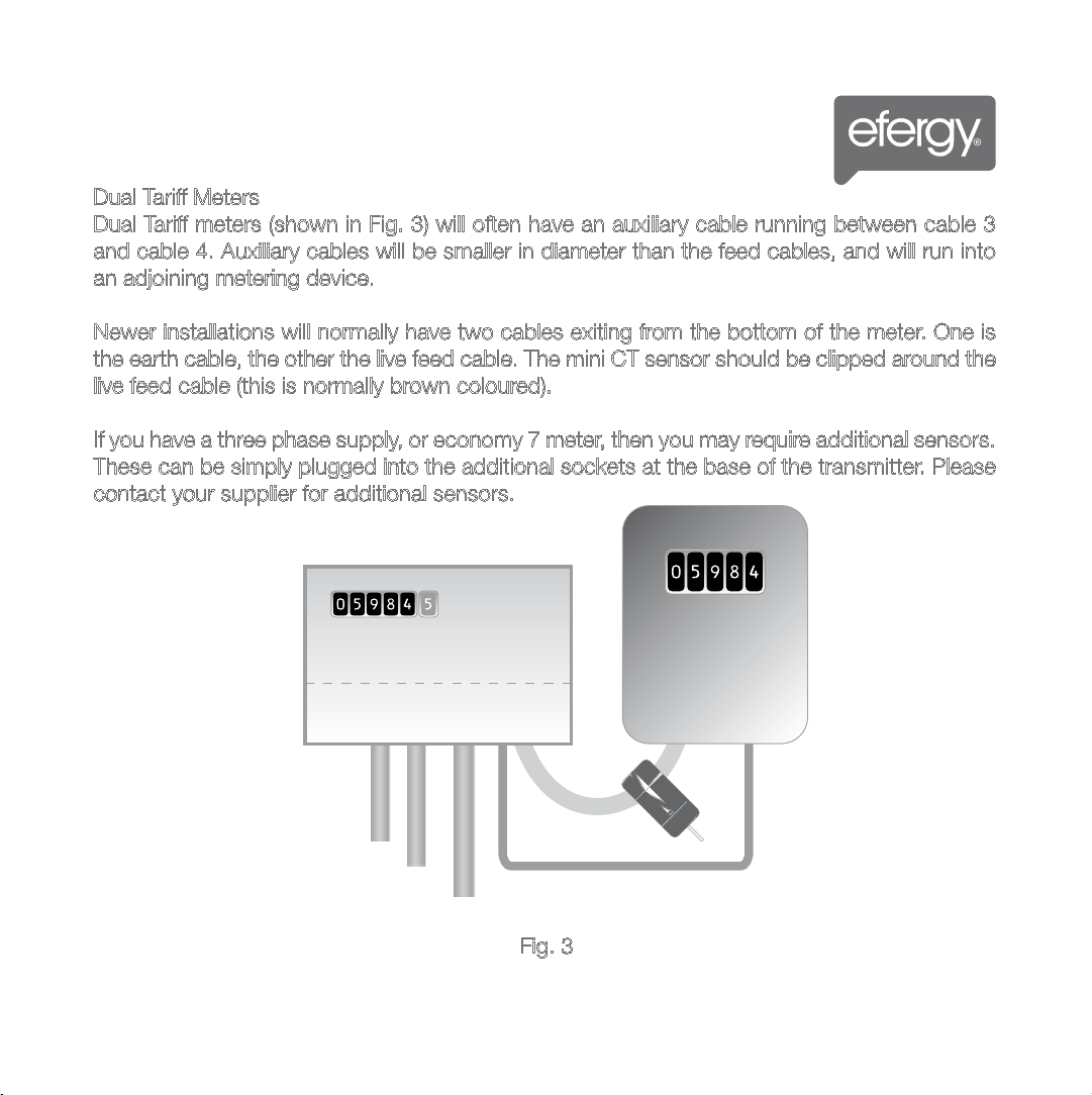
Dual Tariff Meters
Dual Tariff meters (shown in Fig. 3) will often have an auxiliary cable running between cable 3
and cable 4. Auxiliary cables will be smaller in diameter than the feed cables, and will run into
an adjoining metering device.
Newer installations will normally have two cables exiting from the bottom of the meter. One is
the earth cable, the other the live feed cable. The mini CT sensor should be clipped around the
live feed cable (this is normally brown coloured).
If you have a three phase supply, or economy 7 meter, then you may require additional sensors.
These can be simply plugged into the additional sockets at the base of the transmitter. Please
contact your supplier for additional sensors.
Auxilary Cable
1
2
3
4
1
2
3
4
Fig. 1
Fig. 3
1
2
3
4
Fig. 2
MOUNTING INDIVIDUAL OR MULTIPLE CIRCUITS
Loading ...
Loading ...
Loading ...