Loading ...
Loading ...
Loading ...
PUMP TO TANK INSTALLATION
Red Lion® recommends using pre-charged diaphragm tanks. Instructions
for connecting the pump to a diaphragm tank have been provided for
your convenience.
If a non-diaphragm tank is used in the pressure system, an air volume
control must be used to maintain an air cushion in the pressure tank. If
not, air in the tank will gradually be absorbed by water, causing the tank
to water log and the pump to short cycle (turn o and on frequently). This
greatly shortens the life of the motor. An air volume control will provide
the right air/water ratio and prevent water logging. Refer to the pressure
tank owner’s manual for instructions.
NOTE: A check valve should never be installed between the pump
and the tank.
Before proceeding, ensure power has been shut o at the breaker. If this
is replacing an existing pump, completely relieve pressure from the water
system before working on the water system. Open the faucet nearest the
tank and allow the water to drain until the tank is empty.
s WARNING
!
75 PSI PRESSURE RELIEF VALVE RECOMMENDED
This pump is capable of producing high pressure. Installing a 75 psi
pressure relief valve is highly recommended.
1. The discharge pipe from the pump to the tank should be as short and
direct as possible and should be the same size as the discharge outlet.
You should have already attached a 1" PVC adapter to the discharge
opening of the pump.
2. Attach a PVC 90° elbow to the adapter.
3. Attach a male PVC adapter to the tank. The tank fitting size depends
on the system connect on the tank.
4. Install a 1" brass tank tee to the tank adapter.
5. Measure the distance from the tank tee to the elbow (or restrictor
valve) on the pump’s discharge and attach 1" PVC piping to fit.
6. Attach accessories to the brass tee such as restrictor valve
(recommended for well point installations), high pressure safety relief
valve (recommended for all installations), and drain cock. Ensure the
high pressure safety relief valve’s location is near the discharge of the
pump, in an area with adequate drainage. Be sure to direct the valve
so that any water flow will not spray toward the pump or any other
electrical devices.
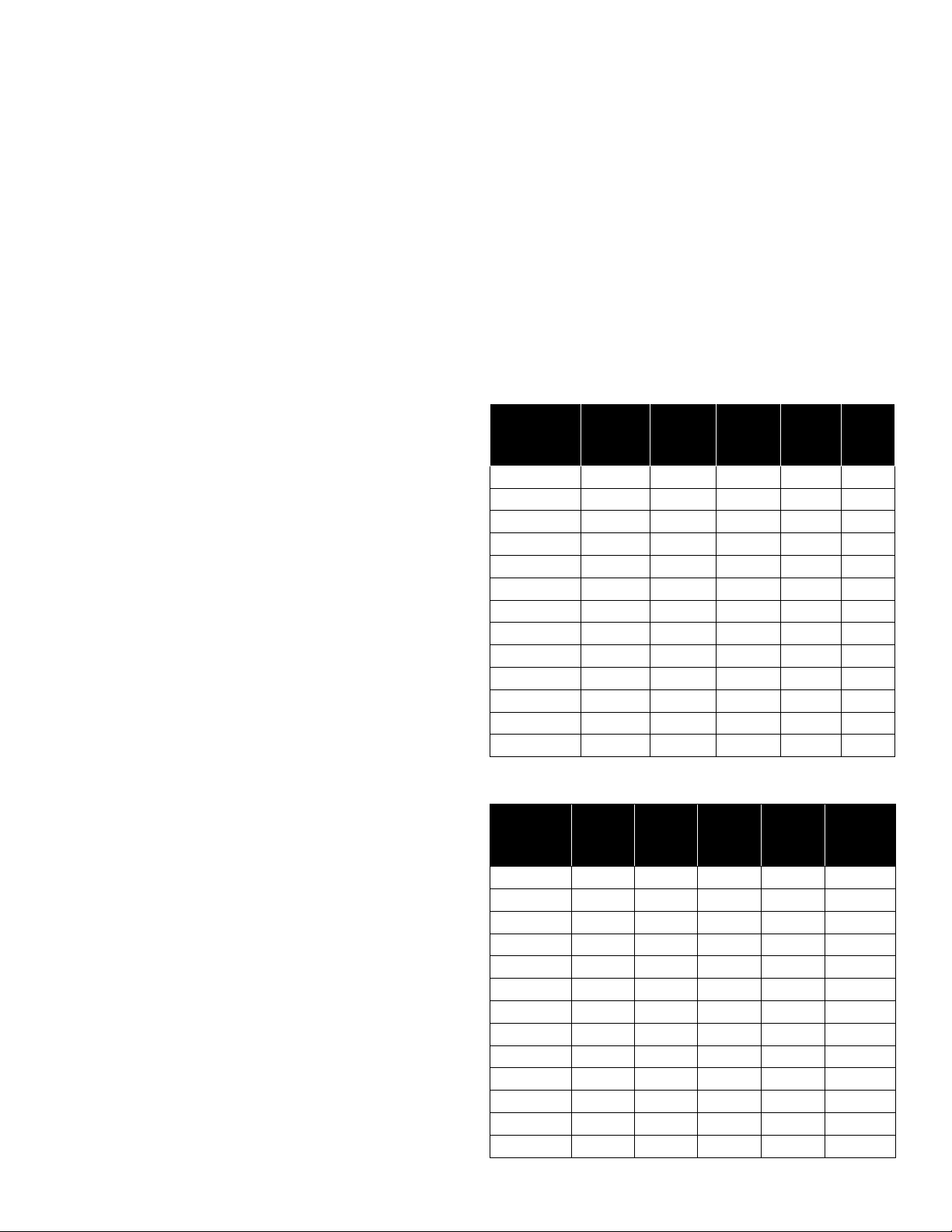
7. Add piping and coupling to join up the service line. The size of the
service line required is governed entirely by the amount of water
needed and the length of the pipe. The pipe selected should be large
enough so that the friction loss (determined from Table 1, Friction
Loss for Plastic Pipe) will never exceed 20 ft (6 m) of head.
8. Remove the PVC cap on the air valve on the tank.
9. Check the tank pre-charge with a tire gauge. It should be equal to
2 psi below the pressure switch cut-in setting (the pressure at which
the pump will start). For this pump that is 30 psi, therefore the
pre-charge pressure should be adjusted to 28 psi. Use a tire pump
or air compressor to charge the tank, if necessary.
10. Replace and tighten the PVC cap on the air valve.
11. See Typical Installations for examples of dierent
pump/tank configurations.
12. Verify everything has been completed using the Installation
Checklist provided in this manual.
Nominal
Pipe Size
U.S. GPM 3/4" 1" 1-1/4'' 1-1/2'' 2''
4 3.75 1.15 0.30 0.14 –
5 5.66 1.75 0.46 0.22 –
6 7.95 2.45 0.65 0.31 –
7 10.60 3.25 0.86 0.41 –
8 13.50 4.16 1.10 0.52 –
9 16.80 5.17 1.35 0.65 –
10 20.40 6.31 1.67 0.79 0.23
11 24.40 7.58 1.98 0.95 0.27
12 28.60 8.85 2.33 1.10 0.32
14 38.00 11.80 3.10 1.46 0.43
16 48.60 15.10 3.96 1.87 0.55
18 60.50 18.70 4.93 2.33 0.69
20 73.50 22.80 6.00 2.83 0.84
Nominal
Pipe Size
L/Min. 20mm 25mm 32mm 40mm 50mm
15 3.7 1.15 0.30 0.13 –
20 5.3 1.64 0.43 0.19 –
25 7.1 2.18 0.56 0.27 –
30 13.5 4.13 1.08 0.49 –
35 16.3 5.00 1.31 0.61 –
40 23.5 7.30 1.90 0.88 0.25
45 28.3 8.74 2.31 1.07 0.29
50 34.2 10.60 2.79 1.32 0.38
55 40.7 12.60 3.32 1.56 0.46
60 48.1 14.90 3.92 1.85 0.54
65 55.7 17.30 4.45 2.15 0.63
70 63.8 19.70 5.20 2.46 0.73
75 72.2 22.40 5.89 2.78 0.83
Loss of head in feet due to friction per 100 feet of pipe.
Loss of head in meters, due to friction per 100 meters of pipe.
Table 1 - FRICTION LOSS FOR PLASTIC PIPE*
*For galvanized pipe, double the figures.
10
Loading ...
Loading ...
Loading ...