Loading ...
Loading ...
Foot
Valve/Strainer
Suction pipe
Well seal
Before You Install Your Pump
NOTICE
1. The pump’s water suction inlet must not be move
than 20’ above the water level.
2. Long runs and many ttings increase friction
and reduce water ow to the pump. Locate pump
as close to water source as possible; use as few
elbows and ttings as possible. Be sure suction
line is straight and angles up toward pump to
avoid air lock.
3. Be sure well and pipe are clear of sand, dirt and
scale. Foreign matter will plug pump and void
warranty. Use new pipe for best results.
4. Protect pump and all piping from freezing.
Freezing will split pipe, damage pump and void
warranty. Check locally for frost protection require
ments. Pipe cannot be installed above frost line
and pump must be insulated.
5. Foot or check valves must be installed in suction
pipe to optimize pump suction.
6. Be sure all pipes and valves are clean and in
good shape.
7. No air pockets in suction pipe.
8. No leaks in suction pipe. Use Teon tape or
other approved sealants to seal pipe joints.
9. Unions installed near pump and well will aid in
servicing. Leave room to use wrenches.
Risk of explosion.
Do not ground to a gas supply line.
Pump body may explode if used as a booster pump
or other than a lawn sprinkling application.
Risk of burns.
Motor normally operates at high temperature and will
be too hot to touch. It is protected from heat dam-
age during operation by an automatic internal cuto
switch.
Before handling pump or motor, stop motor and allow
it to cool for 20 minutes.
Well Pipe Installation
NOTICE : It is recommended that pump be in-
stalled in well ventilated enclosure
Use installation method below which matches your
water source.
3
INSTALLATION
!
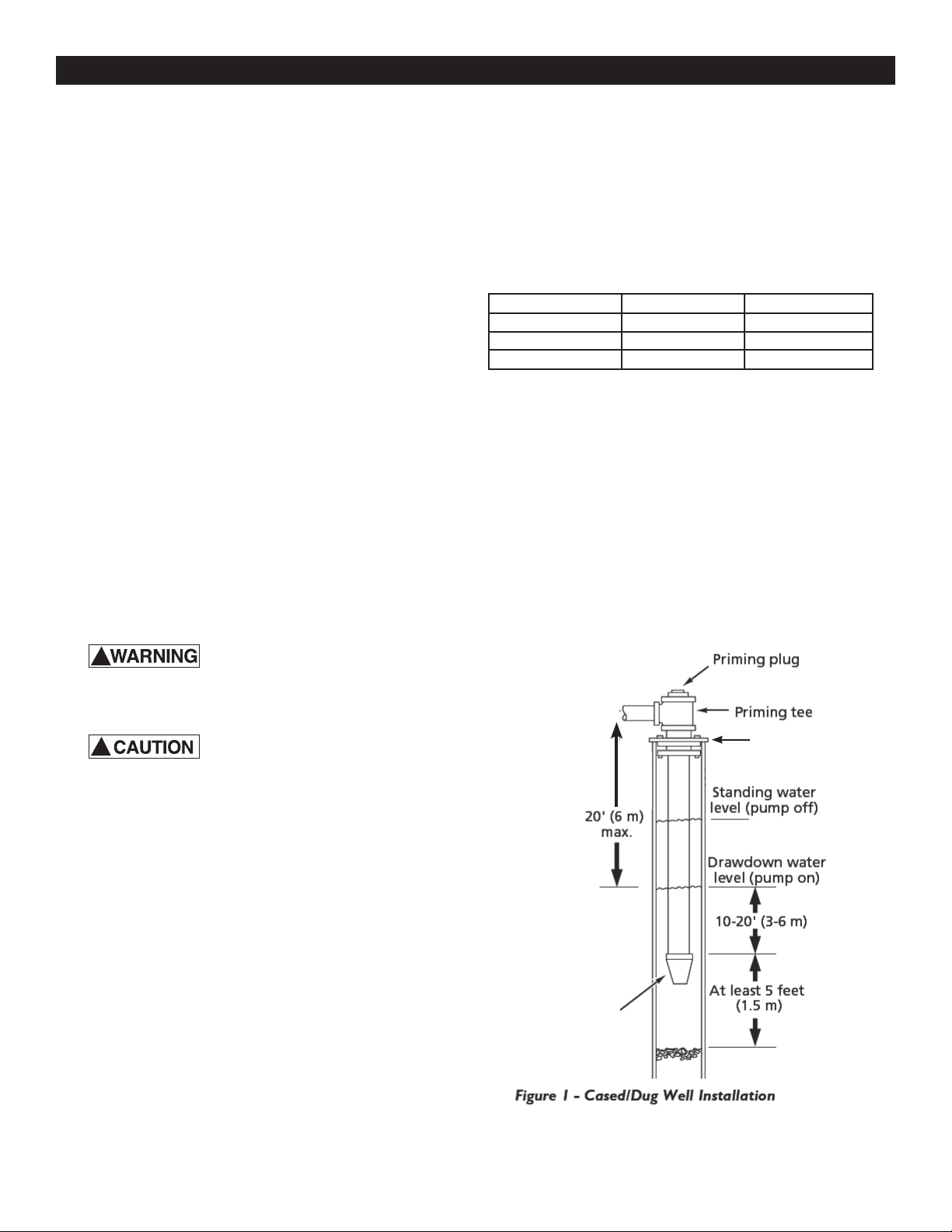
Cased Well/Dug Well Installation
1. Inspect foot or in line check valve to be sure it
works freely. Inspect strainer to be sure it is clean
and secure.
2. If using foot valve, connect foot valve and strainer
to rst length of suction pipe and lower pipe into
well. Add sections of pipe as needed, using Teon
tape on male threads.
Be sure all suction pipe is leak proof or pump will
lose prime and fail to pump. Install foot valve 10 to
20 ft. (3 to 6 m) below lowest level to which water
will drop while pump is operating (pumping water
level). Your well driller can furnish this information.
3. To prevent sand and sediment from entering
pumping system, foot valve/strainer should be at
least 5 ft. (1.5 m) above bottom of well.
4. When proper depth is reached, install sanitary well
seal over pipe and in well casing. Tighten bolts to
seal casing.
5. When using foot valve, a priming tee and plug are
recommended. (Fig. 1).
!
NOTE: For Maxillum Performance, be sure to select
pipe size for your pump shown below:
Pump Model Suction Outlet
WA10PLS 2” Pipe 1-1/2” Pipe
WA15PLS 2” Pipe 1-1/2” Pipe
WA20PLS 2” Pipe 2” Pipe
Loading ...
Loading ...
Loading ...