User Manual Laundry
INSTALLATION REQUIREMENTS
TOOLS AND PARTS
Gather the required tools and parts before starting installation. Read and follow the instructions provided with any tools listed here.
Tools needed for all installations:
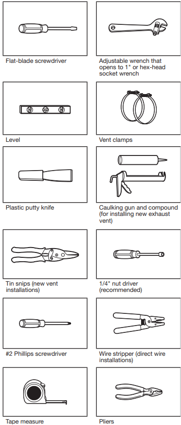
Tools needed for gas installations:
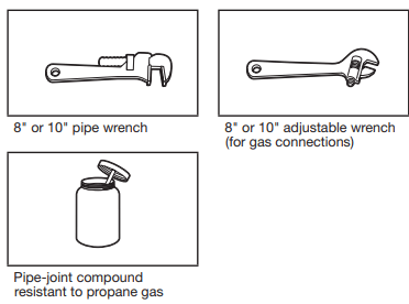
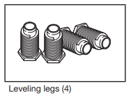
Parts supplied (all models):
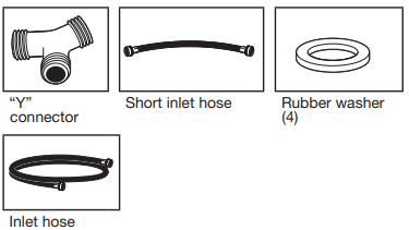
Parts needed (steam models):
If using a power supply cord:
Use a UL listed power supply cord kit marked for use with clothes dryers. The kit should contain:
- A UL listed 30 A power supply cord, rated 120/240 V minimum, with a temperature rating of 140°F (60°C) minimum. The cord should be type SRD or SRDT and be at least 4 ft. (1.22 m) long. The wires that connect to the dryer must end in ring terminals or spade terminals with upturned ends.
- A UL listed strain relief
Parts needed: (Not supplied with dryer) Check local codes. Check existing electrical supply and venting. See “Electrical Requirements” and “Venting Requirements” before purchasing parts.
Mobile home installations require metal exhaust system hardware available for purchase from the dealer from whom you purchased your dryer. For further information, please refer to the “Assistance or Service” section in your “Quick Reference Guide.”
LOCATION REQUIREMENTS
You will need:
- A location allowing for proper exhaust installation. See “Venting Requirements.”
- A separate 15 or 20 A circuit needed for gas dryers and 30 A circuit needed for electric dryers.
- If using power supply cord, a grounded electrical outlet located within 2 ft. (610 mm) of either side of dryer. See “Electrical Requirements.”
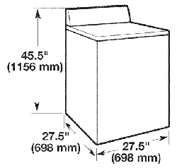
- Floor must support dryer weight of 200 lbs. (90.7 kg). Also consider weight of companion appliance.
- Level floor with maximum slope of 1" (25 mm) under entire dryer. If slope is greater than 1" (25 mm), clothes may not tumble properly and automatic sensor cycles may not operate correctly.
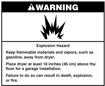
- For garage installation, place dryer at least 18" (460 mm) above floor.
- Steam models only: Cold water faucets located within 4 ft. (1.2 m) of the water fill valves, and water pressure of 20-100 psi (137.9-689.6 kPa). You may use your washer’s water supply by purchasing the necessary parts noted in “Parts needed.”
IMPORTANT: Do not operate, install, or store dryer where it will be exposed to water, weather, or at temperatures below 45°F (7°C). Lower temperatures may cause dryer not to shut off at end of automatic sensor cycles, resulting in longer drying times. NOTE: No other fuel-burning appliance can be installed in the same closet as a dryer.
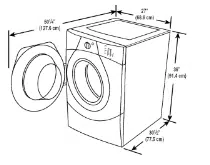
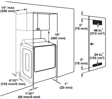
INSTALLATION CLEARANCES
For each arrangement, consider allowing more space for ease of installation and servicing, spacing for companion appliances and clearances for walls, doors, and floor moldings. Space must be large enough to allow door to fully open. Add spacing on all sides of dryer to reduce noise transfer. If a closet door or louvered door is installed, top and bottom air openings in door are required.
Check code requirements. Some codes limit, or do not permit, installation of the dryer in garages, closets, mobile homes, or sleeping quarters. Contact your local building inspector.
Spacing for recessed area or closet installation
The dimensions shown are for the recommended spacing allowed.
- Additional spacing should be considered for ease of installation and servicing.
- Additional clearances might be required for wall, door, and floor moldings.
- Additional spacing of 1" (25 mm) on all sides of the dryer is recommended to reduce noise transfer.
- For closet installation, with a door, minimum ventilation openings in the top and bottom of the door are required. Louvered doors with equivalent ventilations openings are acceptable.
- Companion appliance spacing should also be considered
Mobile home - Additional installation requirements:
This dryer is suitable for mobile home installations.
The installation must conform to the Manufactured Home Construction and Safety Standard, Title 24 CFR, Part 3280 (formerly the Federal Standard for Mobile home construction and Safety, Title 24, HUD Part 280) or Standard CAN/CSA-Z240 MH.
Mobile home installations require:
All dryers:
- Metal exhaust system hardware, available for purchase from your dealer. For further information, see “Assistance or Service” section in your “Quick Reference Guide.”
- Special provisions must be made in mobile homes to introduce outside air into dryer. Openings (such as a nearby window) should be at least twice as large as dryer exhaust opening.
For gas dryers mobile home installations:
- Mobile Home Installation Hold-down Kit is available to order. For further information, see “Assistance or Service” section in your “Quick Reference Guide.”
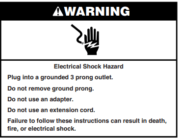
ELECTRICAL REQUIREMENTS - U.S.A. ONLY
It is your responsibility:
- To contact a qualified electrical installer.
- To be sure that the electrical connection is adequate and in conformance with the National Electrical Code, ANSI/NFPA 70 - latest edition and all local codes and ordinances.
The National Electrical Code requires a 4-wire power supply connection for homes built after 1996, dryer circuits involved in remodeling after 1996, and all mobile home installations.
A copy of the above code standards can be obtained from: National Fire Protection Association, One Batterymarch Park, Quincy, MA 02269.
- To supply the required 3 or 4-wire, single phase, 120/240 V, 60 Hz, AC only electrical supply (or 3 or 4-wire, 120/208 V electrical supply, if specified on the serial/rating plate) on a separate 30 A circuit, fused on both sides of the line. Connect to an individual branch circuit. Do not have a fuse in the neutral or grounding circuit.
- Do not use an extension cord.
- If codes permit and a separate ground wire is used, it is recommended that a qualified electrician determine that the ground path is adequate.
Electrical Connection
To properly install your dryer, you must determine the type of electrical connection you will be using and follow the instructions provided for it here.
- This dryer is manufactured ready to install with a 3-wire electrical supply connection. The neutral ground conductor is permanently connected to the neutral conductor (white wire) within the dryer. If the dryer is installed with a 4-wire electrical supply connection, the neutral ground conductor must be removed from the external ground connector (green screw), and secured under the neutral terminal (center or white wire) of the terminal block. When the neutral ground conductor is secured under the neutral terminal (center or white wire) of the terminal block, the dryer cabinet is isolated from the neutral conductor.
- If local codes do not permit the connection of a neutral ground wire to the neutral wire, see “Optional 3-wire connection” section.
- A 4-wire power supply connection must be used when the appliance is installed in a location where grounding through the neutral conductor is prohibited. Grounding through the neutral is prohibited for (1) new branch-circuit installations, (2) mobile homes, (3) recreational vehicles, and (4) areas where local codes prohibit grounding through the neutral conductors.
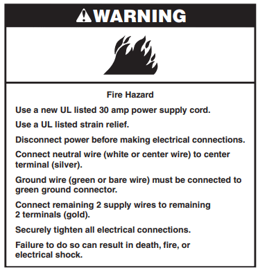
If using a power supply cord:
Use a UL listed power supply cord kit marked for use with clothes dryers. The kit should contain:
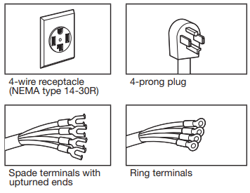
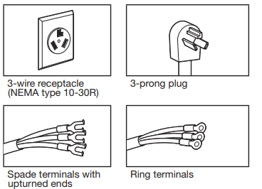
- A UL listed 30 A power supply cord, rated 120/240 V minimum, with a temperature rating of 140°F (60°C) minimum. The cord should be type SRD or SRDT, and be at least 4 ft. (1.22 m) long. The wires that connect to the dryer must end in ring terminals or spade terminals with upturned ends.
- A UL listed strain relief.
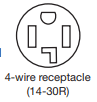
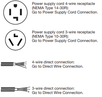
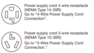
If your outlet looks like this:
 Then choose a 4-wire power supply cord with ring or spade terminals and UL listed strain relief. The 4-wire power supply cord, at least 4 ft. (1.22 m) long, must have 4 10-gauge solid copper wires and match a 4-wire receptacle of NEMA Type 14-30 R. The ground wire (ground conductor) may be either green or bare. The neutral conductor must be identified by a white cover.
If your outlet looks like this:
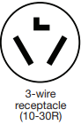 Then choose a 3-wire power supply cord with ring or spade terminals and UL listed strain relief. The 3-wire power supply cord, at least 4 ft. (1.22 m) long, must have 3 10-gauge solid copper wires and match a 3-wire receptacle of NEMA Type 10-30 R.
If connecting by direct wire:
Power supply cable must match power supply (4-wire or 3-wire) and be:
- Flexible armored cable or nonmetallic sheathed copper cable (with ground wire), covered with flexible metallic conduit. All current-carrying wires must be insulated.
- 10-gauge solid copper wire (do not use aluminum) at least 5 ft. (1.52 m) long.
ELECTRIC DRYER POWER HOOKUP - CANADA ONLY
ELECTRICAL REQUIREMENTS
It is your responsibility:
- To contact a qualified electrical installer.
- To be sure that the electrical connection is adequate and in conformance with Canadian Electrical Code, C22.1-latest edition and all local codes. A copy of above codes standard may be obtained from: Canadian Standards Association, 178 Rexdale Blvd., Toronto, ON M9W 1R3 CANADA.
- To supply the required 4-wire, single phase, 120/240 V, 60 Hz, AC only electrical supply on a separate 30 A circuit, fused on both sides of the line. A time-delay fuse or circuit breaker is recommended. Connect to an individual branch circuit.
- This dryer is equipped with a UL listed and/or CSA International Certified Power Cord intended to be plugged into a standard 14-30R wall receptacle.The cord is 5 ft. (1.52 m) long. Be sure wall receptacle is within reach of dryer's final location.
For further information, please reference service numbers located in “Assistance or Service” section of your “Quick Reference Guide.”
GAS DRYER POWER HOOKUP - U.S.A. AND CANADA
ELECTRICAL REQUIREMENTS
- ■ 120 V, 60 Hz, AC only, 15 or 20 A fused electrical supply is required. A time-delay fuse or circuit breaker is recommended. It is also recommended that a separate circuit serving only this dryer be provided
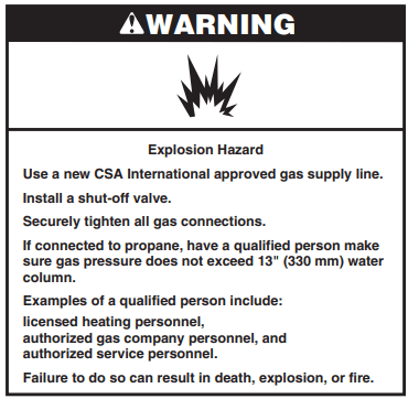
GAS SUPPLY REQUIREMENTS
GAS TYPE
Natural Gas:
This dryer is equipped for use with Natural gas. It is certified by UL for use with propane gas with appropriate conversion.
- Your dryer must have the correct burner for the type of gas in your home. Burner information is located on the rating plate in the door well of your dryer. If this information does not agree with the type of gas available, contact your dealer or call the phone numbers referenced in the “Assistance or Service” section of your “Quick Reference Guide.”
Propane Gas Conversion:
IMPORTANT: Conversion must be made by a qualified technician. No attempt shall be made to convert the dryer from the gas specified on the model/serial rating plate for use with a different gas without consulting your gas company.
GAS SUPPLY LINE
Option 1 (Recommended Method)
Flexible stainless steel gas connector:
- If local codes permit, use a new flexible stainless steel gas connector (Design Certified by the American Gas Association or CSA International) to connect your dryer to the rigid gas supply line. Use an elbow and a 3/8" flare x 3/8" NPT adapter fitting between the stainless steel gas connector and the dryer gas pipe as needed to prevent kinking.
Option 2 (Alternate Method)
Approved aluminum or copper tubing
- Must include 1/8" NPT minimum plugged tapping accessible for test gauge connection, immediately upstream of the gas connection to the dryer.
- 1/2" IPS pipe is recommended.
- 3/8" approved aluminum or copper tubing is acceptable for lengths under 20 ft. (6.1 m) if local codes and gas supplier permit.
- If you are using Natural gas, do not use copper tubing.
- Lengths over 20 ft. (6.1 m) should use larger tubing and a different size adapter fitting.
- If your dryer has been converted to use LP gas, 3/8" propane compatible copper tubing can be used. If the total length of the supply line is more than 20 ft. (6.1 m), use larger pipe.
NOTE: Pipe-joint compounds that resist the action of propane gas must be used. Do not use TEFLON®† tape.
- Must include shut-off valve
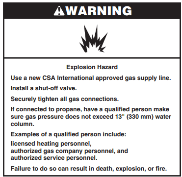
In the U.S.A.:
An individual manual shut-off valve must be installed within six (6) ft. (1.8 m) of the dryer in accordance with the National Fuel Gas Code, ANSI Z223.1. The location should be easy to reach for opening and closing.
In Canada:
An individual manual shut-off valve must be installed in accordance with the B149.1, Natural Gas and Propane Installation Code. It is recommended that an individual manual shutoff valve be installed within six (6) ft. (1.8 m) of the dryer. The location should be easy to reach for opening and closing.
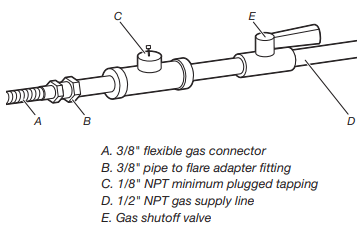
GAS SUPPLY CONNECTION REQUIREMENTS
- Use an elbow and a 3/8" flare x 3/8" NPT adapter fitting between the flexible gas connector and the dryer gas pipe, as needed to avoid kinking.
- Use only pipe-joint compound. Do not use TEFLON®† tape.
- This dryer must be connected to the gas supply line with a listed flexible gas connector that complies with the standard for connectors for gas appliances, ANSI Z21.24 or CSA 6.10.
BURNER INPUT REQUIREMENTS
Elevations above 2,000 ft. (610 m):
- When installed above 2,000 ft. (610 m) a 4% reduction of the burner Btu rating shown on the model/serial number plate is required for each 1,000 ft. (305 m) increase in elevation.
Gas supply pressure testing
- The dryer must be disconnected from the gas supply piping system during pressure testing at pressures greater than 1/2 psi.
DRYER GAS PIPE
- The gas pipe that comes out through the rear of your dryer has a 3/8" male pipe thread.
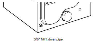
NOTE: For a garage installation, the gas pipe height must be an additional 18" (460 mm) from the floor.
INSTALL LEVELING LEGS
1. Prepare dryer for leveling legs
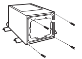
Firmly grasp dryer body (not console panel) and gently lay dryer down on back cardboard corner posts.
IMPORTANT: If laying dryer on its back, use the cardboard corner posts the dryer was packed with to avoid damaging the back of the dryer.
2. Screw in leveling legs
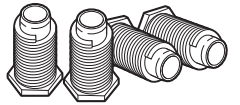
Using a wrench and tape measure, screw leveling legs into leg holes until bottom of foot is approximately 1" (25 mm) from bottom of dryer. Now stand the dryer on its feet. Slide the dryer until it is close to its final location. Leave enough room to connect the exhaust vent.
For mobile home use
Gas dryers must be securely fastened to the floor.
Mobile home installations require a Mobile Home Installation Hold-down Kit. For ordering information please reference the “Quick Reference Guide.”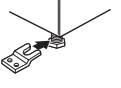
MAKE ELECTRICAL CONNECTION - U.S.A. ONLY
ELECTRICAL CONNECTION
Power Supply Cord
Electrical Connection Options
1. Choose electrical connection type
NOTE: If local codes do not permit connection of a cabinet-ground conductor to neutral wire, go to “Optional 3-wire connection.” This connection may be used with either a power supply cord or a direct wire connection.
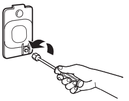
2. Remove terminal block cover
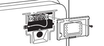
Remove hold-down screw and terminal block cover.
POWER SUPPLY CORD CONNECTION
Power Supply Cord Strain Relief
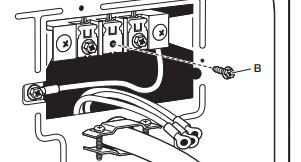
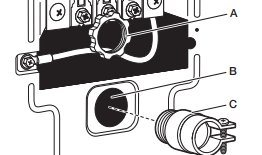
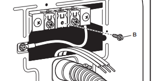
1. Attach power supply cord strain relief
Remove the screws from a 3/4" (19 mm) UL Listed strain relief. Put the tabs of the two clamp sections (C) into the hole below the terminal block opening (B) so that one tab is pointing up (A) and the other is pointing down (D), and hold in place. Tighten strain relief screws just enough to hold the two clamp sections (C) together.
2. Attach power supply cord strain relief
Put power supply cord through the strain relief. Be sure that the wire insulation on the power supply cord is inside the strain relief. The strain relief should have a tight fit with the dryer cabinet and be in a horizontal position. Do not further tighten strain relief screws at this point.
If your outlet looks like this:
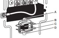
4-wire Power Supply Cord Connection
IMPORTANT: A 4-wire connection is required for mobile homes and where local codes do not permit the use of 3-wire connections.
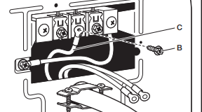
1. Prepare to connect neutral ground wire and neutral wire
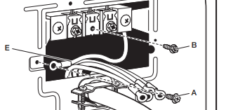
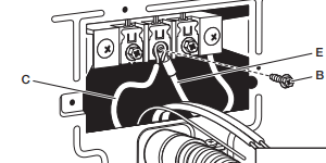
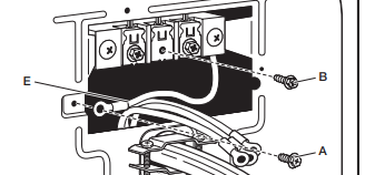
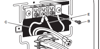
Remove center terminal block screw (B). Remove neutral ground wire (E) from external ground conductor screw (A).
2. Connect neutral ground wire and neutral wire
Connect neutral ground wire (E) and neutral wire (white) (C) of power supply cord under center terminal block screw (B). Tighten screw.
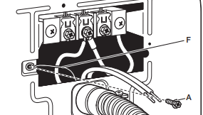
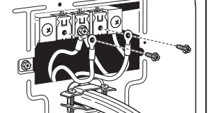
3. Connect ground wire
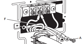
Connect ground wire (F) (green or bare) of power supply cord to external ground conductor screw (A). Tighten screw.
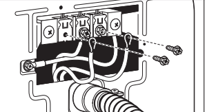
4. Connect remaining wires
Connect remaining wires to outer terminal block screws. Tighten screws. Finally, reinsert tab of terminal block cover into slot of dryer rear panel. Secure cover with hold-down screw. Now, go to “Venting Requirements.”
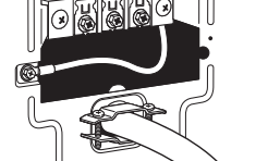
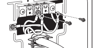
3-wire Power Supply Cord Connection
Use where local codes permit connecting cabinet-ground conductor to neutral wire.
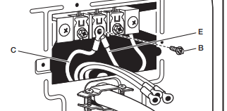
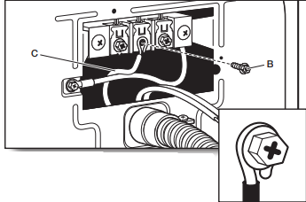
1. Remove center screw
Remove center terminal block screw (B).
2. Connect neutral wire
Connect neutral wire (white or center) (C) of power supply cord to center terminal block screw (B). Tighten screw.
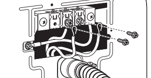
3. Connect remaining wires
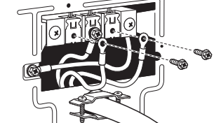
Connect remaining wires to outer terminal block screws. Tighten screws. Finally, reinsert tab of terminal block cover into slot of dryer rear panel. Secure cover with hold-down screw. Now, go to “Venting Requirements.”
DIRECT WIRE CONNECTION
Direct Wire Strain Relief
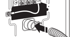
1. Attach direct wire strain relief
Unscrew the removable conduit connector (A) and any screws from a 3/4" (19 mm) UL Listed strain relief.
Put the threaded section of the strain relief (C) through the hole below the terminal block opening (B). Reaching inside the terminal block opening, screw the removable conduit connector (A) onto the strain relief threads.
2. Attach direct wire cable to strain relief
Put direct wire cable through the strain relief. The strain relief should have a tight fit with the dryer cabinet and be in a horizontal position. Tighten strain relief screw against the direct wire cable.
If your wiring looks like this:
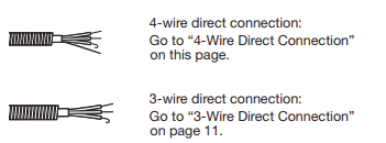
4-wire Direct Wire Connection
IMPORTANT: A 4-wire connection is required for mobile homes and where local codes do not permit 3-wire connections.
1. Prepare your 4-wire cable for direct connection
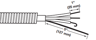
Direct wire cable must have 5 ft. (1.52 m) of extra length so dryer may be moved if needed.
Strip 5" (127 mm) of outer covering from end of cable, leaving bare ground wire at 5" (127 mm). Cut 11/2" (38 mm) from remaining 3 wires. Strip insulation back 1" (25 mm). Shape ends of wires into hooks.
2. Prepare to connect neutral ground wire and neutral wire
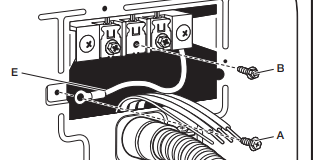
Remove center terminal block screw (B). Remove neutral ground wire (E) from external ground conductor screw (A).
3. Connect neutral ground wire and neutral wire
Connect neutral ground wire (E) and place hooked end (hook facing right) of neutral wire (white or center wire) (C) of direct wire cable under center screw of terminal block (B). Squeeze hooked ends together and tighten screw.

4. Connect ground wire
Connect ground wire (green or bare) (F) of direct wire cable to external ground conductor screw (A). Tighten screw.
5. Connect remaining wires
Place hooked ends of remaining direct wire cable wires under outer terminal block screws (hooks facing right). Squeeze hooked ends together and tighten screws. Finally, reinsert tab of terminal block cover into slot of dryer rear panel. Secure cover with hold�down screw. Now, go to “Venting Requirements.”
3-wire Direct Wire Connection
Use where local codes permit connecting cabinet-ground conductor to neutral wire.
1. Prepare your 3-wire cable for direct connection
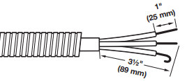
Direct wire cable must have 5 ft. (1.52 m) of extra length so dryer may be moved if needed.
Strip 31/2" (89 mm) of outer covering from end of cable. Strip insulation back 1" (25 mm). If using 3-wire cable with ground wire, cut bare wire even with outer covering. Shape wire ends into hooks.
2. Remove center screw
Remove center terminal block screw (B).
3. Connect neutral wire
Place hooked end of neutral wire (white or center) (C) of direct wire cable under center terminal block screw (B). Squeeze hooked end together. Tighten screw.
4. Connect remaining wires
Place hooked ends of remaining direct wire cable wires under outer terminal block screws (hooks facing right). Squeeze hooked ends together and tighten screws. Finally, reinsert tab of terminal block cover into slot of dryer rear panel. Secure cover with hold-down screw. Now, go to “Venting Requirements.”
Optional 3-wire Connection
You must verify with a qualified electrician that this grounding method is acceptable before connecting.
1. Prepare to connect neutral ground wire and neutral wire
Remove center terminal block screw (B). Remove neutral ground wire (E) from external ground conductor screw (A)
2. Connect neutral ground wire and neutral wire
Connect neutral ground wire (E) and neutral wire (white or center wire) (C) of power supply cord or cable under center terminal block screw (B). Tighten screw.
3. Connect remaining wires
Connect remaining wires to outer terminal block screws Tighten screws.
4. Connect external ground wire
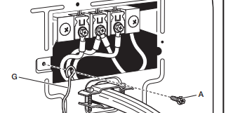
Connect a separate copper ground wire (G) from the external ground conductor screw (A) to an adequate ground. Finally, reinsert tab of terminal block cover into slot of dryer rear panel. Secure cover with hold-down screw. Now, go to “Venting Requirements.”
MAKE GAS CONNECTION - U.S.A. AND CANADA
1. Connect gas supply to dryer
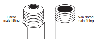
Remove red cap from gas pipe. Using a wrench to tighten, connect gas supply to dryer. Use pipe-joint compound on threads of all non-flared male fittings. If flexible metal tubing is used, be sure there are no kinks.
NOTE: For propane gas connections, you must use pipe-joint compound resistant to action of propane gas. Do not use TEFLON®† tape.
2. Plan pipe fitting connection
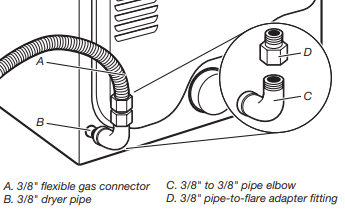
A combination of pipe fittings must be used to connect dryer to existing gas line. Recommended connection is shown. Your connection may be different, according to supply line type, size, and location.
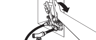
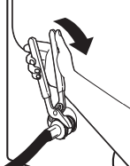
3. Open shut-off valve
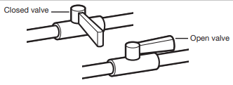
Open shut-off valve in supply line; valve is open when handle is parallel to gas pipe. Then, test all connections by brushing on an approved noncorrosive leak-detection solution. Bubbles will show a leak. Correct any leaks found.
VENTING
VENTING REQUIREMENTS
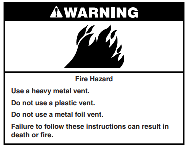
IMPORTANT: Observe all governing codes and ordinances. Dryer exhaust must not be connected into any gas vent, chimney, wall, ceiling, attic, crawl space, or a concealed space of a building. Only rigid or flexible metal vent shall be used for exhausting.
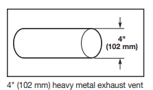
- Only a 4" (102 mm) heavy metal exhaust vent and clamps may be used.
- Do not use plastic or metal foil vent.
Rigid metal vent:
- Recommended for best drying performance and to avoid crushing and kinking.
Flexible metal vent: (Acceptable only if accessible to clean)
- Must be fully extended and supported in final dryer location.
- Remove excess to avoid sagging and kinking that may result in reduced airflow and poor performance.
- Do not install in enclosed walls, ceilings, or floors.
- The total length should not exceed 73 /4 ft. (2.4 m).
- The length of flexible metal vent used must be included in the overall vent system design as shown in the “Vent System Charts.”
NOTE: If using an existing vent system, clean lint from entire length of the system and make sure exhaust hood is not plugged with lint. Replace plastic or metal foil vents with rigid metal or flexible metal vents. Review Vent System Chart and, if necessary, modify existing vent system to achieve best drying performance.
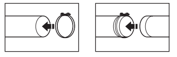
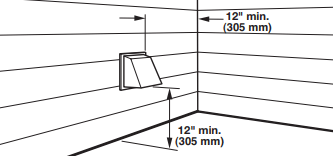
Exhaust hoods:
- Must be at least 12" (305 mm) from ground or any object that may obstruct exhaust (such as flowers, rocks, bushes, or snow).
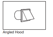
Recommended Styles:
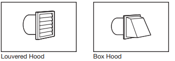
Acceptable Style:
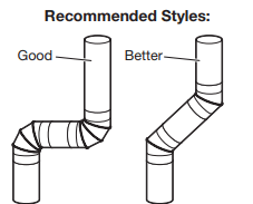
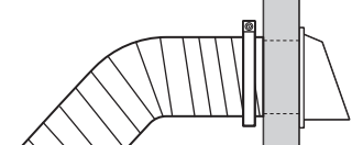
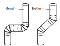
Elbows:
- 45° elbows provide better airflow than 90° elbows.
Clamps:
- Use clamps to seal all joints.
- Exhaust vent must not be connected or secured with screws or other fastening devices that extend into interior of duct and catch lint. Do not use duct tape.
Vent products can be purchased from your dealer. For more information, see “Assistance or Service” section in your “Quick Reference Guide.”
PLAN VENT SYSTEM
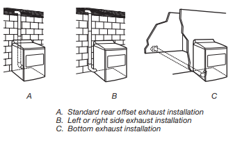
Recommended exhaust installations
Typical installations vent the dryer from the rear of the dryer. Other installations are possible.

Optional exhaust installations:
If you prefer, dryer may be converted to exhaust through the bottom and sides. You must contact your local dealer to have dryer converted.
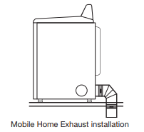
Special provisions for mobile homes:
Exhaust vent must be securely fastened to a noncombustible portion of mobile home and must not terminate beneath the mobile home. Terminate exhaust vent outside.
Determine vent path:
- Select route that will provide straightest and most direct path outdoors.
- Plan installation to use fewest number of elbows and turns.
- When using elbows or making turns, allow as much room as possible.
- Bend vent gradually to avoid kinking.
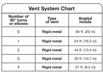
- Use as few 90° turns as possible. Determine vent length and elbows needed for best drying performance:
- Use following Vent System Chart to determine type of vent material and hood combinations acceptable to use. NOTE: Do not use vent runs longer than those specified in Vent System Chart. Exhaust systems longer than those specified will:
- Shorten life of dryer.
- Reduce performance, resulting in longer drying times and increased energy usage.
The Vent System Charts provide venting requirements that will help achieve best drying performance.
INSTALL VENT SYSTEM
1. Install exhaust hood
Install exhaust hood and use caulking compound to seal exterior wall opening around exhaust hood.
2. Connect vent to exhaust hood
Vent must fit over the exhaust hood. Secure vent to exhaust hood with 4" (102 mm) clamp. Run vent to dryer location using straightest path possible. Avoid 90° turns. Use clamps to seal all joints. Do not use duct tape, screws, or other fastening devices that extend into interior of vent to secure vent, because they can catch lint.
CONNECT INLET HOSES
For non-steam models, skip to “Connect Vent.” The dryer must be connected to the cold water faucet using the new inlet hoses. Do not use old hoses.
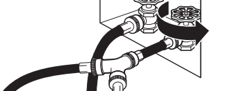
1. Turn cold water off, remove and replace rubber washer
Turn cold water faucet off and remove washer inlet hose.
Remove old rubber washer from inlet hose and replace with new rubber washer.
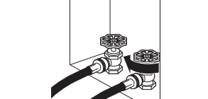
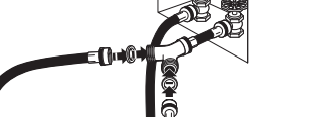
2. Attach short hose and “Y” connector
Attach 2 ft (0.6 m) inlet hose to cold water faucet. Screw on coupling by hand until it is seated on faucet. Then attach “Y” connector to male end of the 2 ft (0.6 m) inlet hose. Screw on coupling by hand until it is seated on connector.
3. Tighten couplings
Using pliers, tighten the couplings with additional two-thirds turn.
NOTE: Do not overtighten. Damage to the coupling can result.
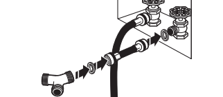
4. Attach long hose to “Y” connector and tighten couplings
Attach dryer 5 ft (1.5 m) inlet hose ends to the “Y” connector. Attach washer cold inlet hose to other side of “Y” connector. Screw on coupling by hand until it is seated on connector. Using pliers, tighten the couplings an additional two-thirds turn.
NOTE: Do not overtighten. Damage to the coupling can result.
5. Attach long hose to dryer fill valve and tighten coupling
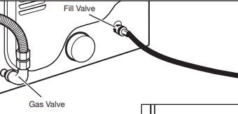
Attach other end of long hose to fill valve at bottom of dryer back panel. Screw on coupling by hand until it is seated on fill valve connector. Using pliers, tighten the couplings an additional two-thirds turn.
NOTE: Do not overtighten. Damage to the coupling can result.
6. Turn on cold water faucet Check that the water faucet is turned on.
7. Check for leaks
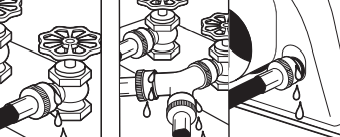
Check for leaks around “Y” connector, faucets, and hoses.
CONNECT VENT
1. Connect vent to exhaust outlet
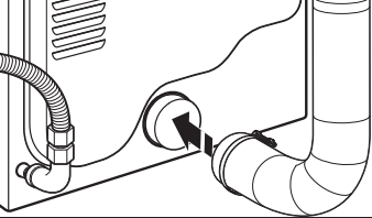
Using a 4" (102 mm) clamp, connect vent to exhaust outlet in dryer. If connecting to existing vent, make sure vent is clean. Dryer vent must fit over dryer exhaust outlet and inside exhaust hood. Check that vent is secured to exhaust hood with a 4" (102 mm) clamp.
2. Move dryer to final location
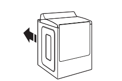
Move dryer to final location. Avoid crushing or kinking vent.
LEVEL DRYER
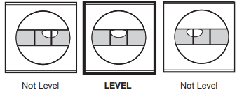
1. Level Dryer
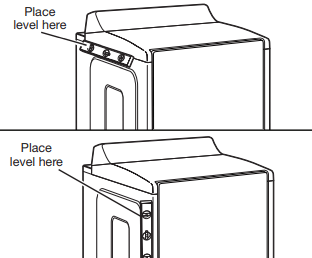
Check levelness of dryer from side to side. Repeat from front to back.
NOTE: The dryer must be level for the moisture sensing system to operate correctly.
2. Adjust leveling legs
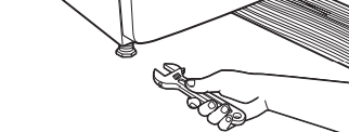
If dryer is not level, prop up using a wood block. Use wrench to adjust legs up or down, and check again for levelness. Locating Pins Locking Features
3. Base trim (on some models)
To Install:
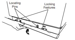
Place the base trim to bottom of dryer and match the locating pins with the holes. Press the base trim firmly upwards until it snaps into place.
To Remove:
On each corner. 1) Push down on top of base trim. 2) Rotate away from dryer and remove.
DRYER DOOR (ON SOME MODELS)
For normal dryer use, it is not suggested to remove the dryer door. However, if removal is necessary, make sure the dryer is off and cool. Then, follow these instructions. The dryer door is heavy.
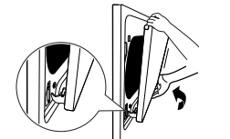
To Remove:
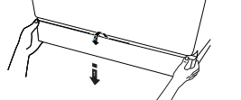
1. Open dryer door all the way.
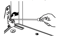
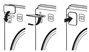
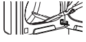
2. Use flat head screw drive to open hinge latch.
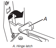
3. Pinch the hinge latch between two fingers and pull forward. Repeat on other side of dryer door.
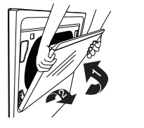
4. Close the dryer door as far as it will shut.
5. Lift the dryer door while holding both sides. Continue to push the dryer door closed and pull it away from the dryer door frame.
To Replace:
1. Insert both hanger arms into the front panel.
2. Open the dryer door.
You should hear a “click” as the door is set into place.
3. Move the hinge levers back to the locked position. Check that the door is free to open and close. If it is not, repeat the removal and installation procedures.
DOOR REVERSAL (ON SOME MODELS)
The following instructions are applicable for models with side opening door.
Tools Needed:
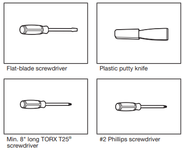
You can change your door swing from a right-side opening to a left-side opening, if desired.
1. Place a towel or soft cloth on top of dryer or work space to avoid damaging the surface.
Remove door from dryer cabinet
1. Open the dryer door.
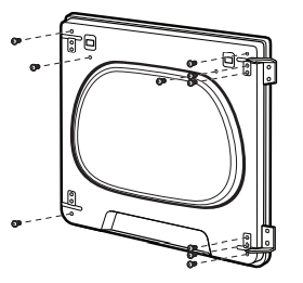
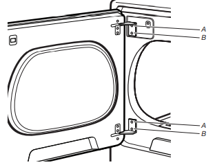
2. Using a T25® screwdriver, remove screws (A) and then (B) screws from each of the two hinges that attach dryer door to front panel of dryer. Set the hinge screws off to the side for reinstalling the door.
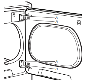
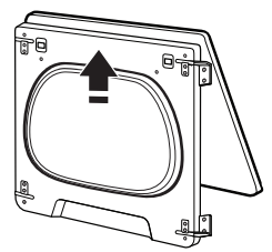
3. Remove the dryer door by lifting upward and out to lift the door off the cabinet. Lay the door on a flat, covered surface,with the inside of the door facing up.
4. Remove the 2 plastic plugs (A) located outside the dryer door opening.
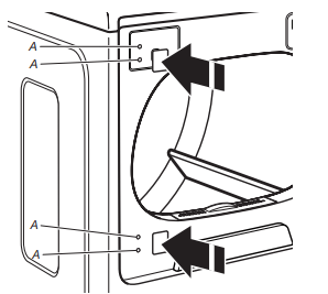
5. Install 2 plastic plugs (A) into screw holes where the hinges were removed in Step 4.
Reverse the strike
1. Remove the door strike (A) from the dryer door opening.
2. Remove the cosmetic screw (B) opposite the door strike (A).
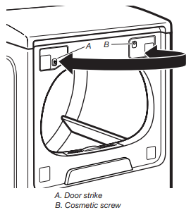
3. Reinstall the door strike and cosmetic screw on the opposite side of dryer door opening from where they were removed.
NOTE: Door strike and plugs must be on the same side of the dryer door opening.
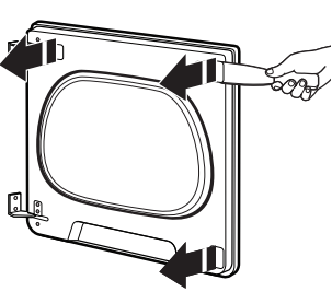
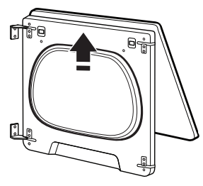
Remove the door assembly
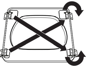
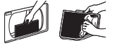
1. Lay the door on a flat, covered surface with the inside of the door facing up. Remove the 3 plugs with a plastic putty knife. There is a cut out to stick the putty knife under to pop out.
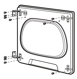
2. Remove the 10 screws from the dryer door and setscrews off to the side.
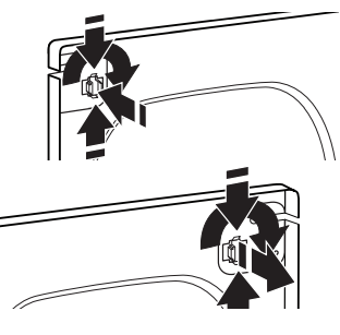
3. Remove the inner door by using a plastic putty knife to separate the sides and bottom of the dryer door and trim. There are 2 snaps on left, right, and bottom of door. Insert the putty knife next to the snaps.
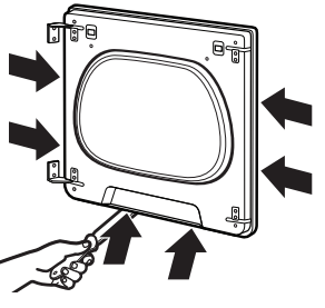
4. When you have the door separated from the frame, use a putty knife to lift up in the center tab and then pull door toward you and out.
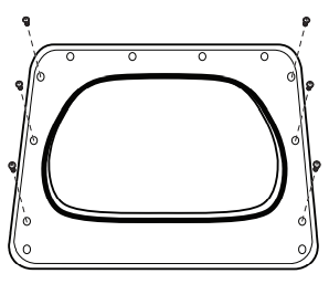
5. Remove the door strike plug with a flathead screwdriver. Remove door strike by pinching the clips from the inside door panel and then rotate and push out the front. Insert door strike on the other side of dryer door by pushing in and then add the door strike plug.
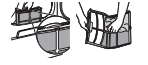
6. Remove the door hinges and set off to the side.
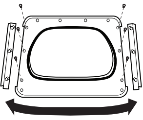
7. Remove the 3 screws down the left and right sides of the door to remove the outer trim pieces.
8. Lift door up and rotate trim pieces to the opposite side from which they were removed. Then screw trim pieces back in.
9. Add the hinges to the right side of the door and then flip the hinge labeled 1 to the bottom of the right side and the hinge labeled 2 to the top of the right side of the door.
10. Add inside door panel back into the dryer door by sliding the top into the top trim piece and then lower door down. Then press down on the corners to snap into place with the hinges lined up with the hinge holes.
11. Install 6 hinge screws and the other 4 screws.
12. Install hinge covers and plugs. Hinge covers will go inside ways to then rotate 90° and snap into place.
13. Hang door by placing set pin in dryer cabinet hole and slide door down. Using a T25® screwdriver, install (A) screws and then (B) screws. Tighten all hinge screws.
DRYER CARE
CLEANING THE DRYER LOCATION
Keep dryer area clear and free from items that would block the airflow for proper dryer operation. This includes clearing piles of laundry in front of the dryer.
CLEANING THE DRYER INTERIOR
To clean dryer drum
1. Use a mild hand dish detergent mixed at a low concentration with very warm water, and rub with a soft cloth.
2. Rinse well with a wet sponge or towel.
3. Tumble a load of clean clothes or towels to dry drum
OR
Use a microfiber cloth and hot water in a spray bottle to clean the drum and a second microfiber towel to dry.
NOTE: Garments that contain unstable dyes, such as denim blue jeans or brightly colored cotton items, may discolor the rear of the dryer interior. These stains are not harmful to your dryer and will not stain future loads of clothes. Dry unstable dye items inside out to avoid transfer of dye.
REMOVING ACCUMULATED LINT
From Inside the Dryer
Cabinet Lint should be removed every 2 years, or more often, depending on dryer usage. Cleaning should be done by a qualified appliance servicer or ventilation system cleaner.
From the Exhaust Vent
Lint should be removed every 2 years, or more often, depending on dryer usage.
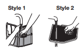
CLEANING THE LINT SCREEN
Every load cleaning The lint screen is located in the door opening of the dryer. A screen blocked by lint can increase drying time.
To clean:
Style 1
1. Pull the lint screen straight up and out. Press tab down on front and open lint screen. Roll lint off the screen with your fingers. Do not rinse or wash screen to remove lint. Wet lint is hard to remove.
Style 2
1. Pull the lint screen out of its holder. Roll lint off the screen with your fingers. Do not rinse or wash screen to remove lint. Wet lint is hard to remove.
2. Push the lint screen firmly back into place.
IMPORTANT:
- Do not run the dryer with the lint screen loose, damaged, blocked, or missing. Doing so can cause overheating and damage to both the dryer and fabrics.
- If lint falls off the screen into the dryer during removal, check the exhaust hood and remove the lint. See “Venting Requirements” in the Installation Instructions.
- Clean space where lint screen is located, as needed. Using a vacuum, gently remove any lint that has accumulated outside of the lint screen.
As-needed cleaning
Laundry detergent and fabric softener residue can build up on the lint screen. This buildup can cause longer drying times for your clothes, or cause the dryer to stop before your load is completely dry. The screen is probably clogged if lint falls off while the screen is in the dryer. Clean the lint screen with a nylon brush every 6 months, or more frequently, if it becomes clogged due to a residue buildup.
To wash:
1. Roll lint off the screen with your fingers.
2. Wet both sides of lint screen with hot water.
3. Wet a nylon brush with hot water and liquid detergent. Scrub lint screen with the brush to remove residue buildup.
4. Rinse screen with hot water.
5. Thoroughly dry lint screen with a clean towel. Reinstall screen in dryer.
CHANGING THE DRUM LIGHT (ON SOME MODELS)
1. Unplug dryer or disconnect power.
2. Open the dryer door. Locate the light bulb cover on the back wall of the dryer. Using a 1/4" (6 mm) nut driver or socket wrench, remove the screw located in the lower right-hand corner of the cover. Remove the cover.
3. Turn bulb counterclockwise. Replace the bulb with a 10 W appliance bulb only. Replace the cover and secure with the screw.
4. Plug into a grounded outlet or reconnect power.
CHECK YOUR VENT SYSTEM FOR GOOD AIR FLOW
GOOD AIR FLOW
Along with heat, dryers require good air flow to efficiently dry laundry. Proper venting will reduce your drying times and improve your energy savings. See Installation Instructions.
The venting system attached to the dryer plays a big role in good air flow. Blocked or crushed vents as well as improper venting installation will reduce air flow and dryer performance.
Service calls caused by improper venting are not covered by the warranty and will be paid by the customer, regardless of who installed the dryer. To clean or repair venting, contact a venting specialist.
MAINTAIN GOOD AIR FLOW BY:
- Cleaning your lint screen before each load
- Replace plastic or foil vent material with 4" (102 mm) diameter heavy, rigid vent material.

- Use the shortest length of vent possible.
- Use no more than four 90° elbows in a vent system; each bend and curve reduces air flow.
- Remove lint and debris from the exhaust hood.
- Remove lint from the entire length of the vent system at least every 2 years. When cleaning is complete, be sure to follow the Installation Instructions supplied with your dryer for final product check.
- Clear away items from the front of the dryer.
NON-USE, STORAGE, AND MOVING CARE
Steam models only: Install and store your dryer where it will not freeze. Because some water may stay in the hose, freezing can damage your dryer. If storing or moving your dryer during freezing weather, winterize it.
Non-Use or Storage Care
If you will be on vacation or not using your dryer for an extended period of time, you should:
1. Unplug dryer or disconnect power.
2. Clean lint screen. See “Cleaning the Lint Screen.”
3. Turn off the water supply to the dryer. This helps to avoid unintended flooding (due to a water pressure surge) while you are away.
Moving Care
For power supply cord-connected dryers:
1. Unplug the power supply cord.
2. Gas models only: Close shut-off valve in gas supply line.
3. Gas models only: Disconnect gas supply line pipe and remove fittings attached to dryer pipe.
4. Gas models only: Cap the open fuel supply line.
5. Steam models only: Shut off water faucet.
6. Steam models only: Disconnect the water inlet hose from faucet, then drain the hose. Transport hose separately.
7. Make sure leveling legs are secure in dryer base.
8. Use tape to secure dryer door.
9. On models with base trim: Remove base trim before moving dryer. See "Base trim".
For direct-wired dryers:
1. Disconnect power.
2. Disconnect wiring from dryer and secure wire ends.
3. Steam models only: Shut off water faucet.
4. Steam models only: Disconnect the water inlet hose from faucet; then drain the hose. Transport hose separately.
5. Make sure leveling legs are secure in dryer base.
6. Use tape to secure dryer door.
7. On models with base trim: Remove base trim before moving dryer. See "Base trim".
Reinstalling the Dryer
Follow the Installation Instructions to locate, level, and connect the dryer. SPECIAL INSTRUCTIONS
FOR STEAM MODELS
Water Inlet Hose
Replace inlet hose and hose screen after 5 years of use to reduce the risk of hose failure. Periodically inspect and replace inlet hose if bulges, kinks, cuts, wear, or leaks are found.
When replacing your inlet hose, record the date of replacement.
To Winterize the Dryer
1. Unplug dryer or disconnect power.
2. Shut off water faucet.
3. Disconnect water inlet hose from faucet and drain.
To Use the Dryer Again
1. Flush water pipes. Reconnect water inlet hose to faucet. Turn on water faucet.
2. Plug in dryer or reconnect power as described in the Installation Instructions.