Loading ...
Loading ...
Loading ...
Installing a domestic appliance can be a complicated operation which if not carried out correctly, can seriously affect consumer
safety. It is for this reason that the task should be undertaken by a professionally qualified person who will carry it out in
accordance with the technical regulations in force. In the event that this advice is ignored and the installation is carried out
by an unqualified person, the manufacturer declines all responsibility for any technical failure of the product whether or not
it results in damage to goods or injury to individuals.
8 GB
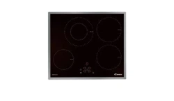
BUILT-IN
The furniture in which your hob will be installed and all adjacent
furniture, should be made from materials that can withstand high
temperatures. In addition, all decorative laminates should be fixed
with heat-resistant glue.
Installation:
• A watertight seal is supplied with the hob.
Before fitting:
- turn the hob upside down, with the glass surface facing downwards.
Make sure the glass is protected.
- fit the seal round the hob.
- make sure that it is correctly fitted to avoid any leakage into the
supporting cabinet.
• Leave a gap of at least 5 cm between the appliance and the
vertical sides of the adjacent furniture.
• If, when installing the hob, the lower hob face is adjacent to an
area normally accessible when handling or cleaning, fit a partition
1 cm (7 cm for PVS) below the base of the hob to avoid any risk
of scorching or damage.
INSTALLATION
"The installation must conform to the standard directives."
The manufacturer declines all responsibility for any damage that
may be caused by unsuitable or unreasonable use.
Warning :
• Always check before any electrical operation, the supply tension
shown on the electricity meter, the adjustment of the circuit-
breaker, the continuity of the connection to earth to the installation
and that the fuse is suitable.
• The electrical connection to the installation should be made via
a socket with a plug with earth, or via an omnipole cut-out switch
with an opening gap of at least 3 mm.
If the appliance has a socket outlet, it must be installed so that
the socket outlet is accessible.
• The yellow/green wire of the power supply cable must be
connected to the earth of both power supply and appliance
terminals.
• The manufacturer cannot be held responsible for any accidents
resulting from the use of an appliance which is not connected
to earth, or with a faulty earth connection continuity.
• Any queries regarding the power supply cord should be referred
to After Sales Service or a qualified technician.
ELECTRICAL CONNECTION
min 10 mm PVK -PVD
min 70 mm PVS
Sp da 25 a 45 mm
Accessible
space
Seal
Hob
min 70 cm
min 15 cm
min 5,5 cm
10 mm
mini
50 mm
Opening
500 X 50
Opening
500 X 10
It is forbidden
to fit the hob
above a non-
ventilated oven
3 G 2,5 mm2
H05RR-F,
H05VV-F,
H05V2V2-F
3 G 2,5 mm2
H05RR-F,
H05VV-F,
H05V2V2-F
4 G 2,5 mm2
H05RR-F,
H05VV-F,
H05V2V2-F
4 G 2,5 mm2
H05RR-F,
H05VV-F,
H05V2V2-F
5 G 1,5 mm2
H05RR-F,
H05VV-F,
H05V2V2-F
To proceed with the connection, you must adhere to the following
instructions.
• Before making the connection, make sure that the installation
is protected by a suitable fuse, see table, and that it is fitted
with wires of a large enough section to supply the appliance
normally.
• Choose the supply cord in accordance with the recommendations
in the table.
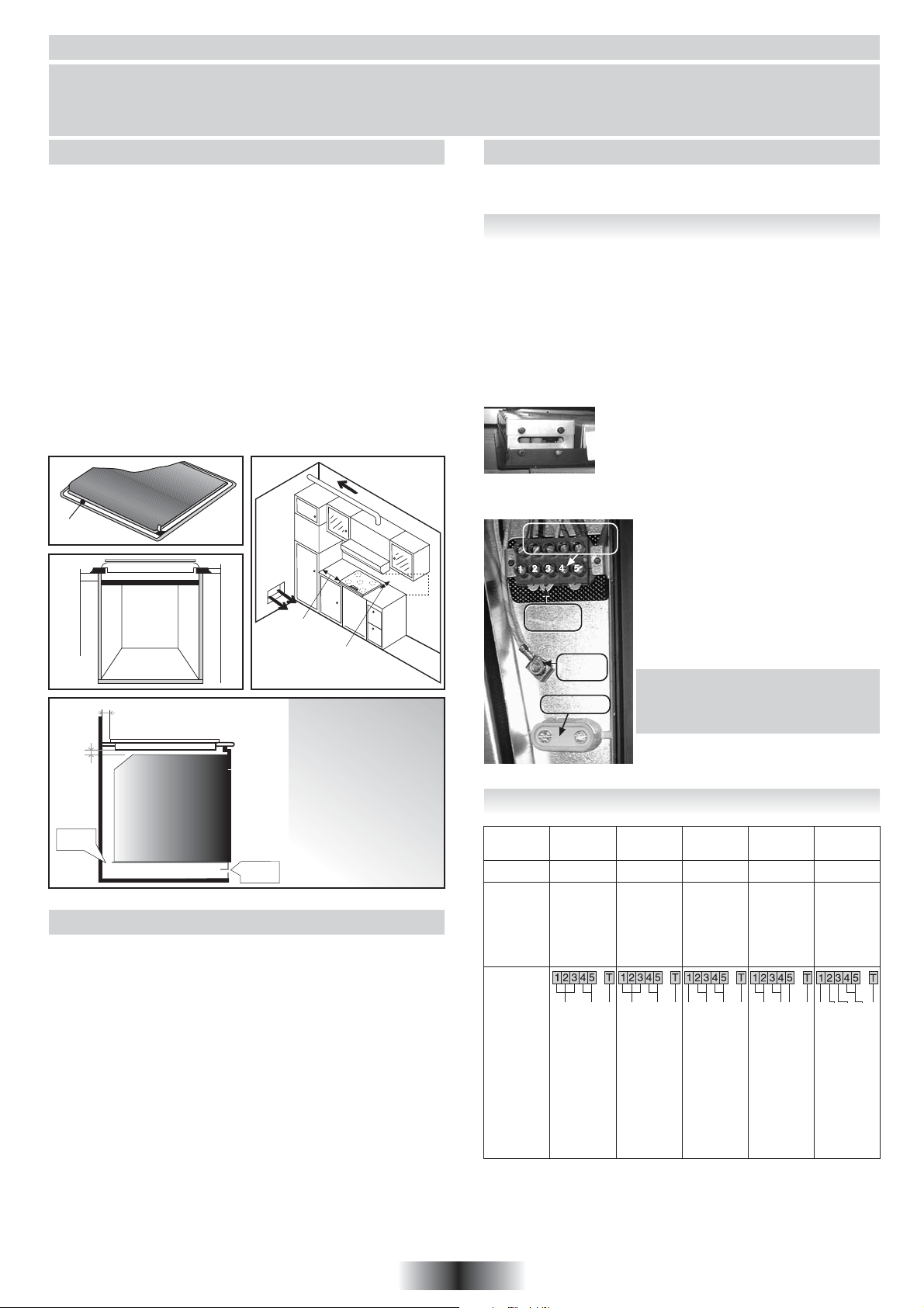
• Turn the hob, with the glass side against the worktop, providing
you have protected the glass !
• Remove the cover located under the control
knobs, fitted by 2 screws at the front.
• Pass the supply cord into the cover hole.
• Pass the supply cord into the clamp.
• Strip the end of each conductor of the supply
cord on a 10 mm length, by taking account of the requested
length of the cord for the connection on the terminal block.
• The terminal block offers different types
of connection.
So, in accordance with installation
instructions and with the help of shunt
bars*, fix the conductors as shown on
the chart.
* The shunt bars, placed on the Earth
Terminal,
allow to make a bridge between two
phases. Screw the screw fully home.
• Screw the cable clamp back.
• Screw the cover hole back do not forget
the fan-lock washers.
• PVK Models
A power cord is not supplied with the appliance, but the hob is
equipped with a terminal block which enables you to choose the
correct connection for the particular power supply.
CONNECTION TO THE TERMINALS ON THE TERMINAL BLOCK:
Terminal block
with marks
Shunts
bars
Earth
Terminal
Cord clamp
Note : Please take care to ensure
that the shunt bars do not fall through
the hole.
ELECTRICAL CONNECTION
Monophase
220-240V~
Two phases
220-240V2~
Two phases
220-415V2N~
Three phases
220-240V3~
Three phases
380-415V3N~
20 A 20 A 20 A 20 A 16 AFUSE
CABLE
AREA
TYPE
PH Phase
shunt 1-2
shunt 2-3
N Neutral
shunt 4-5
T Earth E
CONNEC-
TION TO
THE
TERMIMAL
BLOCK
PH N T PH PH T PH N TPH PHPH PH T TPHPH PH N
PH Phase
shun 1-2
shunt 2-3
PH Phase
shunt 4-5
T Earth E
PH Phase
PH Phase
shunt 2-3
N Neutral
shunt 4-5
T Earth E
PH Phase
shunt 1-2
PH Phase
shunt 3-4
PH Phase
T Earth E
PH Phase
PH Phase
PH Phase
N Neutral
shunt 4-5
T Earth E
Loading ...
Loading ...
Loading ...