Loading ...
Loading ...
Loading ...
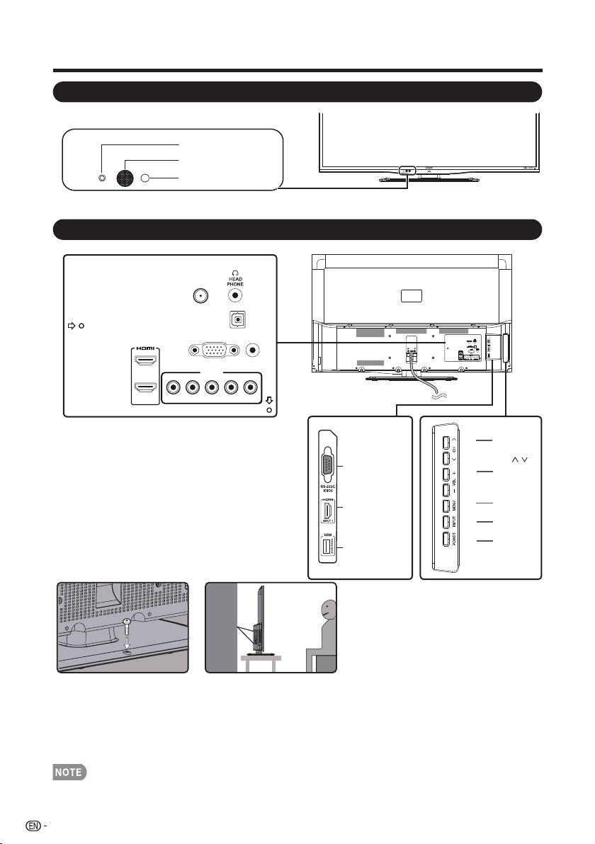
Part Names
*1: See pages 14 to 18 and 35 for external equipment connection.
*1: Optical Picture Control (See Page 27)
*2: See page 14, 19 and 26 for button operations.
• The illustrations in this operation manual are for explanation purposes and may vary slightly from the actual operations.
POWER indicator
OPC sensor
Remote control sensor
12
*1
TV (Front)
TV (Side/Rear)
*2
POWER
button
MENU
button
INPUT
button
Volume
buttons
(VOL
+
/
_
Channel
buttons
(CH
/
)
)
*1
DIGITAL
AUDIO OUTPUT
PC IN
AUDIO
PC/HDMI
INPUT 4
Y/VIDEO PB
PR
L-AUDIO-R
ANT./CABLE
INPUT 2
INPUT 3
*1
USB
RS-232C IOIOI
INPUT 1
Terminal (HDMI)
Anti-tip Auxiliary Screw Hole:
1. In the event of failure to fasten the screws on the table, please use another two bolts( recommended size: T4*22) to fasten the
screws on the wall mount hole and fix the LCD Display to the wall with a wire for safety. (Fig.
Fig. 1 Fig. 2
1)
2. In case that the table on which you place your LCD Display cannot be locked withscrews, use two additional screws (the
recommended size: M6 x 16) to mount the LCD Display via the wall mounting hole in the rear and fasten with a steel wire (Fig. 2)
to ensure safety.
Loading ...
Loading ...
Loading ...