

R Series Arc Trainer
Assembly Instructions
Part Number
1008301-0001 AC


User and Service Documents Link
Operation Manuals and other Product Information available at
https://www.lftechsupport.com/web/document-library/documents
https://www.lftechsupport.com/web/document-library/documents
https://www.lftechsupport.com/web/document-library/documents
https://www.lftechsupport.com/web/document-library/documents
https://www.lftechsupport.com/web/document-library/documents
https://www.lftechsupport.com/web/document-library/documents
Trobareu el manual de funcionament i altra informació de producte a
https://www.lftechsupport.com/web/document-library/documents
Mae Llawlyfrau Gweithredu a Gwybodaeth Arall am Beiriannau ar gael yn
https://www.lftechsupport.com/web/document-library/documents
Die Betriebsanleitung und andere Produktinformationen erhalten Sie unter
https://www.lftechsupport.com/web/document-library/documents
Encontrará el manual de funcionamiento y otra información de producto en
https://www.lftechsupport.com/web/document-library/documents
Erabiltzailearen Eskuliburua eta Beste Produktuei buruzko Informazioa eskuratu
https://www.lftechsupport.com/web/document-library/documents gunean
Käyttöoppaat ja muut tuotetiedot ovat saatavana osoitteessa
https://www.lftechsupport.com/web/document-library/documents
Les manuels d’utilisation, ainsi que d’autres informations sur les Produits, sont disponibles sur
https://www.lftechsupport.com/web/document-library/documents
Felhasználói kézikönyvek és más termékinformációk:
https://www.lftechsupport.com/web/document-library/documents
Manuali di funzionamento e altre informazioni sui prodotti disponibili su
https://www.lftechsupport.com/web/document-library/documents
Instrukcje obsługi i inne informacje o produktach dostępne na stronie
https://www.lftechsupport.com/web/document-library/documents
Manuais de Operação e Informações sobre outros produtos disponíveis em
https://www.lftechsupport.com/web/document-library/documents
https://www.lftechsupport.com/web/document-library/documents
Kullanım Kılavuzları ve Diğer Ürün Bilgileri https://www.lftechsupport.com/web/document-library/documents’da
bulunmaktadır
Page 3 of 47

Corporate Headquarters
Columbia Centre III, 9525 West Bryn Mawr Avenue, Rosemont, Illinois 60018 • U.S.A.
847.288.3300 • FAX: 847.288.3703
Service phone number: 800.351.3737 (toll-free within U.S.A., Canada)
Global Website: www.cybexintl.com
International Offices
All Other EMEA Countries and Distributor Business EMEA*
Bijdorpplein 25-31
2992 LB Barendrecht
THE NETHERLANDS
Telephone: (+31) 180 646 644
United Kingdom
Life Fitness UK LTD
Queen Adelaide
Ely, Cambs, CB7 4UB
Telephone: General Office (+44) 1353.666017
Customer Support (+44) 1353.665507
AMERICAS
North America
Cybex International Inc.
Columbia Centre III
9525 West Bryn Mawr Avenue
Rosemont, IL 60018 U.S.A.
Telephone: (847) 288 3300
ASIA PACIFIC (AP)
Japan
Life Fitness Japan, Ltd
4-17-33 Minami Aoyama 1F/B1F
Minato-ku - Tokyo 107-0062
Japan
Telephone: (+81) 0120.114.482
Fax: (+81) 03-5770-5059
Germany, Austria, and Switzerland
Life Fitness Europe GMBH
Neuhofweg 9
85716 Unterschleißheim
GERMANY
Telephone:
+49 (0) 89 / 31775166 Germany
+43 (0) 1 / 6157198 Austria
+41 (0) 848 / 000901 Switzerland
Brazil
Life Fitness Brasil
Av. Rebouças, 2315
Pinheiros
São Paulo, SP 05401-300
BRAZIL
SAC: 0800 773 8282 option 2
Telephone: +55 (11) 3095 5200 option 2
Hong Kong
Life Fitness Asia Pacific LTD
32/F, Global Trade Square
21 Wong Chuk Hang Road
Hong Kong
Telephone: (+852) 2575.6262
Spain
Life Fitness IBERIA
C/Frederic Mompou 5,1º1ª
08960 Sant Just Desvern Barcelona
SPAIN
Telephone: (+34) 93.672.4660
Latin America and Caribbean*
Life Fitness, Inc.
Columbia Centre III
9525 West Bryn Mawr Avenue
Rosemont, IL 60018 U.S.A.
Telephone: (847) 288 3300
All Other Asia Pacific countries and distributor business Asia
Pacific*
32/F, Global Trade Square
21 Wong Chuk Hang Road
Hong Kong
Telephone: (+852) 2575.6262
Fax: (+852) 2575.6894
Belgium
Life Fitness Benelux NV
Parc Industrial de Petit-Rechain
4800 Verviers
BELGIUM
Telephone: (+32) 87 300 942
EUROPE, MIDDLE EAST, and AFRICA (EMEA)
Netherlands and Luxemburg
Life Fitness Atlantic BV
Bijdorpplein 25-31
2992 LB Barendrecht
THE NETHERLANDS
Telephone: (+31) 180 646 666
*Also check www.cybexintl.com for local representation or distributor/dealer
Page 4 of 47

Table of Contents
Getting Started
Safety Instructions........................................................................................................................6
Consignes de Sécurité..................................................................................................................8
Setup.............................................................................................................................................10
Choosing and Preparing Site....................................................................................................10
Electrical Power Requirements (Applicable for Units Using External Power
Supply).....................................................................................................................................10
Install External Power Supply...................................................................................................11
Check for Console Power..........................................................................................................12
Cable TV Hook Up.......................................................................................................................12
Product Overview
Product Features........................................................................................................................13
Mounting and Dismounting the Arc Trainer..........................................................................13
How to Use the Arc Trainer.......................................................................................................14
Assembly
Assembly Procedure - R Series Lower Body..........................................................................15
Assembly Procedure - R Series Total Body............................................................................27
Service and Technical Data
Preventive Maintenance Tips...................................................................................................42
Approved and Compatible Cleaners.......................................................................................42
Maintenance Schedule..............................................................................................................42
Troubleshooting the Polar
®
Heart Rate Chest Strap............................................................43
Troubleshooting the Lifepulse
™
System Sensors.................................................................43
Drive Belts.....................................................................................................................................43
How to Obtain Product Service...............................................................................................45
Specifications
R Series - Specifications............................................................................................................46
©
Copyright 2019, Cybex International, Inc.
Columbia Center III - 9525 West Bryn Mawr Ave, Rosemont, IL 60018 • 800-351-3737 • 847-288-3700 • FAX 800-216-8893
www.cybexintl.com • 1008301-0001 AC • 2019
Page 5 of 47

Getting Started
Safety Instructions
Read all instructions before use.
Please take special note of the following safety instructions and important points prior to choosing a location and
beginning assembly of the product.
WARNING: Health-related injuries may result from incorrect or excessive use of exercise equipment. Cybex
STRONGLY recommends seeing a physician for a complete medical exam before undertaking an exercise
program, particularly if the user has a family history of high blood pressure or heart disease, is over the age
of 45, smokes, has high cholesterol, is obese, or has not exercised regularly in the past year. If, at any time
while exercising, the user experiences faintness, dizziness, pain, or shortness of breath, he or she must stop
immediately.
WARNING: To reduce the risk of burns, fire, electric shock, or injury, it is imperative to connect each product
to a properly grounded electrical outlet.
WARNING: Heart rate monitoring systems may be inaccurate. Over exercising may result in serious injury
or death. If you feel faint, stop exercising immediately.
WARNING: Ensure that there is at least 23.6" (0.6 m) of clearance behind the product and at least 12" (30
cm) on the sides.
WARNING: The product is not equipped with a free-wheeling feature. Therefore, it cannot be stopped
immediately.
WARNING: Moving parts and fall hazard.
• To avoid serious injury wait until foot plates come to a complete stop before getting off unit.
• The moving parts cannot be stopped immediately, the unit is not equipped with a free wheel.
WARNING: This product can expose you to chemicals including Di-2-ethylhexyl-phthalate, which is known to
the State of California to cause cancer and birth defects or other reproductive harm. For more information go to
http://www.P65Warnings.ca.gov
DANGER: To reduce the risk of electrical shock or injury from moving parts, always unplug product before
cleaning or attempting any maintenance activity.
Keep all body parts, loose clothing, shoelaces, and towels away from moving parts.
• The individual human power required to perform an exercise may be different than the mechanical power
displayed on the product.
• Use caution when mounting or dismounting the product. Before mounting, use the moving arms to bring the
foot plate nearest to you to the lowest position. Use the stationary handlebars whenever additional stability is
required. While exercising, hold onto the moving arms.
• Never face backward while using the product.
• Do not stand or sit on the rear plastic covers of the product.
• Never operate theproduct if it has adamaged power cord or electrical plug,or if it has been dropped,damaged,
or even partially immersed in water. Contact Customer Support Services.
• Position the product so that the power cord plug to the wall is accessible to the user. Make sure that the power
cord is not knotted or twisted and that it is not trapped under any equipment or other objects.
• If the electrical supply cord is damaged, it must be replaced by the manufacturer, an authorized service agent,
or a similarly qualified person to avoid a hazard.
• Always follow the console instructions for proper operation.
Page 6 of 47

• This appliance is not intended for useby persons (including children) with reduced physical, sensory, or mental
capabilities, or lack ofexperience or knowledge unless they have supervision or been given instruction concerning
the use of the appliance by a person responsible for their safety.
• This equipment is not intended for use by children. Keep children under the age of 14 away from the machine.
• Do not use this product outdoors, near swimming pools or in areas of high humidity.
• Never operate the product with the air openings blocked. Keep air openings free of lint, hair, or any other
obstructing material.
• Never insert objects into any opening in these products. If an object should drop inside, turn off the power,
unplug the power cord from the outlet, and carefully retrieve it. If the item cannot bereached, contact Customer
Support Services.
• Never place liquids of any type directly on the unit, except in an accessory tray or holder. Containers with lids
are recommended.
• Do not use these products in bare feet. Always wear shoes. Wear shoes with rubber or high-traction soles. Do
not use shoes with heels, leather soles, cleats or spikes. Make sure no stones are embedded in the soles.
• Do not reach into, or underneath, the unit or tip it on its side during operation.
• Do not allow other people to interfere in any way with the user or equipment during a workout.
• Allow LCD consoles to “normalize” with respect to temperature for one hour before plugging the unit in and
using.
• Use these products for their intended use as described in this manual. Do not use attachments that have not
been recommended by the manufacturer.
• Read all warnings on each product prior to starting a workout.
• If warnings are missing or damaged, please contact Customer Support Services immediately for replacement
warning labels. Warning labels are shipped with every product and should be installed before product is used.
Cybex is not responsible for missing or damaged warning labels.
NOTE: This equipment has been tested and found to comply with the limits for a Class A digital device,
pursuant to part 15 of the FCC rules. These limits are designed to provide reasonable protection against
harmful interference when the equipment is operated in a commercial environment. This equipment
generates, uses and can radiate radio frequency energy, and if not installed and used in accordance with
the instructionmanual, may cause harmfulinterference to radio communications. Operation of this equipment
in a residential area is likely to cause harmful interference in which case the user will be required to correct
the interference at his own expense.
SAVE THESE INSTRUCTIONS FOR FUTURE REFERENCE.
Testing Parameters
Displayed power (Wattage) and speed (Strides Per Minute), were found to meet class A accuracy when compared
with measured power and speed, with adjustable braking positioned in its maximum position, at the following
accuracy test points:
• 150 W, 86 SPM• 25 W, 37 SPM
• 50 W, 52 SPM
• 175 W, 92 SPM
• 100 W, 72 SPM
• 200 W, 97 SPM
Page 7 of 47

Consignes de Sécurité
Lire toutes les instructions avant usage.
Prêtez une attention toute particulière aux instructions de sécurité ci-dessous avant de choisir un emplacement
et de commencer à assembler votre produit.
AVERTISSEMENT: Une utilisation incorrecte ou excessive de l'appareil peut entraîner des blessures. Cybex
Recommande VIVEMENT aux utilisateurs de passer un examen médical complet avant d'entamer un
programme d'entraînement, et tout particulièrement dans les cas suivants : antécédents familiaux
d'hypertension (pression sanguine trop élevée) ou de pathologies cardiaques,utilisateurs de45 ansou plus,
tabagisme, hypercholestérolémie (taux de cholestérol sanguin trop élevé), obésité, absence d'exercice
physique depuis un an ou plus. Si, pendant l'usage de l'appareil, l'utilisateur éprouve un malaise, desvertiges,
des douleurs ou des difficultés à respirer, il doit s'arrêter immédiatement.
AVERTISSEMENT: Pour réduire les risques de brûlures, d’incendies,de décharges électriques ou de blessures,
il est essentiel de brancher chaque appareil sur une prise électrique correctement mise à la terre.
AVERTISSEMENT: Les systèmes de surveillance de la fréquence cardiaque peuvent être inexacts. Un exercice
trop intensif peut entraîner des blessures graves, voire mortelles. En cas de malaise, interrompez
immédiatement l’exercice.
AVERTISSEMENT: Veillez à laisser un dégagement d’au moins 60 cm (23,6 in) derrière l’appareil et d’au
moins 30 cm (12 in.) sur les côtés.
AVERTISSEMENT: L’appareil n’est pas équipé d’une option roue libre. Par conséquent, il ne peut êtrearrêté
instantanément.
AVERTISSEMENT: Pièces mobiles et risque de chute.
• Afin d'éviter des blessures sérieuses, attendez l'arrêt complet des repose-pieds avant de descendre de
l'appareil.
• Les pièces mobiles ne peuvent pas être arrêtées immédiatement, l'unité n'est pas équipée d'une roue
libre.
Danger.: Pour réduire les risques de chocs électriques ou de blessures en raison des pièces mobiles,
débranchez toujours les produits avant de les nettoyer ou de procéder aux tâches d’entretien.
Éloignez-vous ainsi que les vêtements amples, les lacets de chaussure et les serviettes des parties mobiles
de l’appareil.
• La puissance nécessaire à chaque utilisateur pour effectuer un exercicepeut différer dela puissancemécanique
affichée sur l’appareil.
• Montez et descendez avec précaution du produit. Avant de monter, placez le repose-pieds situé de votre côté
en position basse, en vous aidant des bras mobiles. Utilisez les poignées fixes lorsque vous avez besoin de
renforcer votre équilibre. Pendant les exercices, tenez les bras mobiles.
• Ne montez jamais à l’envers sur le produit.
• Ne vous mettez ni debout, ni assis sur les caches en plastique de l’appareil.
• Ne faites jamais fonctionner le produit dont la fiche ou le cordon d’alimentation sont altérés, ni aucun appareil
qui serait tombé, aurait été endommagé ou même partiellement plongé dans l’eau. Contactez le Service
clientèle.
• Placez l’appareil de façon à ce que l’utilisateur ait accès à la fiche du cordon d’alimentation. Assurez-vous que
le cordon d’alimentation n’est pas noué ou tordu et qu’il n’est pas coincé sous un autre appareil ou sous tout
autre objet.
• Si le cordon d’alimentation électrique est endommagé, il doit être remplacé par le fabricant, par un réparateur
agréé ou par une personne qualifiée afin d’éviter tout danger.
Page 8 of 47

• Pour un fonctionnement correct, suivez toujours les instructions de la console.
• Cet appareil n’est pas destiné à être utilisé par des personnes ou des enfants présentant des capacités physiques,
sensorielles ou mentales réduites, ou un manque d’expérience et de connaissances, sauf en cas de supervision
ou d’instructions relatives à son utilisation par une personne responsable de leur sécurité.
• Cet équipement n’est pas destiné à être utilisé par les enfants. Tenez les enfants âgés de moins de 14 ans à
l’écart de la machine.
• N’utilisez pas ce produit à l’extérieur, près d’une piscine ou dans des endroits très humides.
• Ne jamais utiliser le produit en ayant les ouvertures d’air bloquées. Maintenez les bouches d’aération exemptes
de peluches, de cheveux ou de toute autre obstruction.
• N’insérez jamais d’objet dans les ouvertures de cet appareil. Siun objettombe dans l’appareil,mettez ce dernier
hors tension, débranchez le cordon d’alimentation et récupérez l’objet avec précaution. Si vous ne pouvez pas
l’atteindre, contactez le Service clients.
• Ne placez jamais de liquides d’aucune sorte directement sur l’appareil, sauf si vous disposez d’un support ou
d’un plateau pour accessoires.Nous vous recommandons de n’utiliser que des récipientspourvus d’un bouchon.
• N’utilisez pas l’appareil avec les pieds nus. Portez toujoursdes chaussures.Portez des chaussuresavec semelles
en caoutchouc ou antidérapantes. N’utilisez pas de chaussures à talon, à semelle en cuir, à crampons ou à
pointes. Assurez-vous qu’aucun caillou ne s’est incrusté dans les semelles.
• Ne placez pas les mains à l’intérieur ou sous l’appareil ou ne le faites pas basculer sur le côté durant son
fonctionnement.
• Ne laissez aucune personne gêner l’utilisateur ou le fonctionnement de l’appareil pendant l’exercice.
• Laissez les consoles LCD s’adapter à la température ambiante pendant une heure avant de brancher l’appareil
et de l’utiliser.
• Utilisez cet équipement uniquement aux fins auxquelles il est destiné et de la manière décrite dans le présent
manuel. N’utilisez pas d’accessoires non recommandés par le fabricant.
• Lisez les avertissements avant de commencer à vous entraîner.
• Si certaines étiquettes d’avertissement sont manquantes ou endommagées, contactez immédiatement le
Service à la clientèle. Nous vous en fournirons de nouvelles. Les étiquettes d’avertissement sont expédiées
avec les appareils et doivent être installées avant utilisation de ces derniers. Cybex n’est pas responsable des
étiquettes manquantes ou endommagées.
Remarque: Cet équipement a été testé et jugé conforme aux limites des dispositifs numériques de classe A
définies à l'article 15 durèglement de la FCC. Ces limites sont conçues pour assurer une protection raisonnable
contre les interférences nuisibles lorsque l'appareil fonctionne dans un environnement commercial. Cet
équipement génère, utilise et peut émettre des fréquences radio. Il peut causer des interférences nuisibles
aux communications radio s'il n'est pas installé et utilisé conformément aux instructions du présent manuel
d'installation. Le fonctionnement de cet appareil dans une zone résidentielle pourrait provoquer des
interférences nuisibles, que l'utilisateur serait tenu de corriger à ses propres frais.
CONSERVEZ PRÉCIEUSEMENT CES INSTRUCTIONS POUR UNE CONSULTATION ULTÉRIEURE..
Paramètres de test
La puissance affichée (puissance) et la vitesse (foulées par minute), se sont avérées répondre à la précision de la
classe A par rapport à la puissance et la vitesse mesurées, avec le freinage réglable placé en position maximale,
au niveau des points d'essai de précision suivants :
• 150 W, 86 SPM• 25 W, 37 SPM
• 50 W, 52 SPM
• 175 W, 92 SPM
• 100 W, 72 SPM
• 200 W, 97 SPM
Page 9 of 47
Setup
Read the entire manual before setting up the unit.
Choosing and Preparing Site
Before assembling the unit, verify the chosen site meets the following criteria:
• Area is well lit and well ventilated.
• Surface is structurally sound and properly leveled.
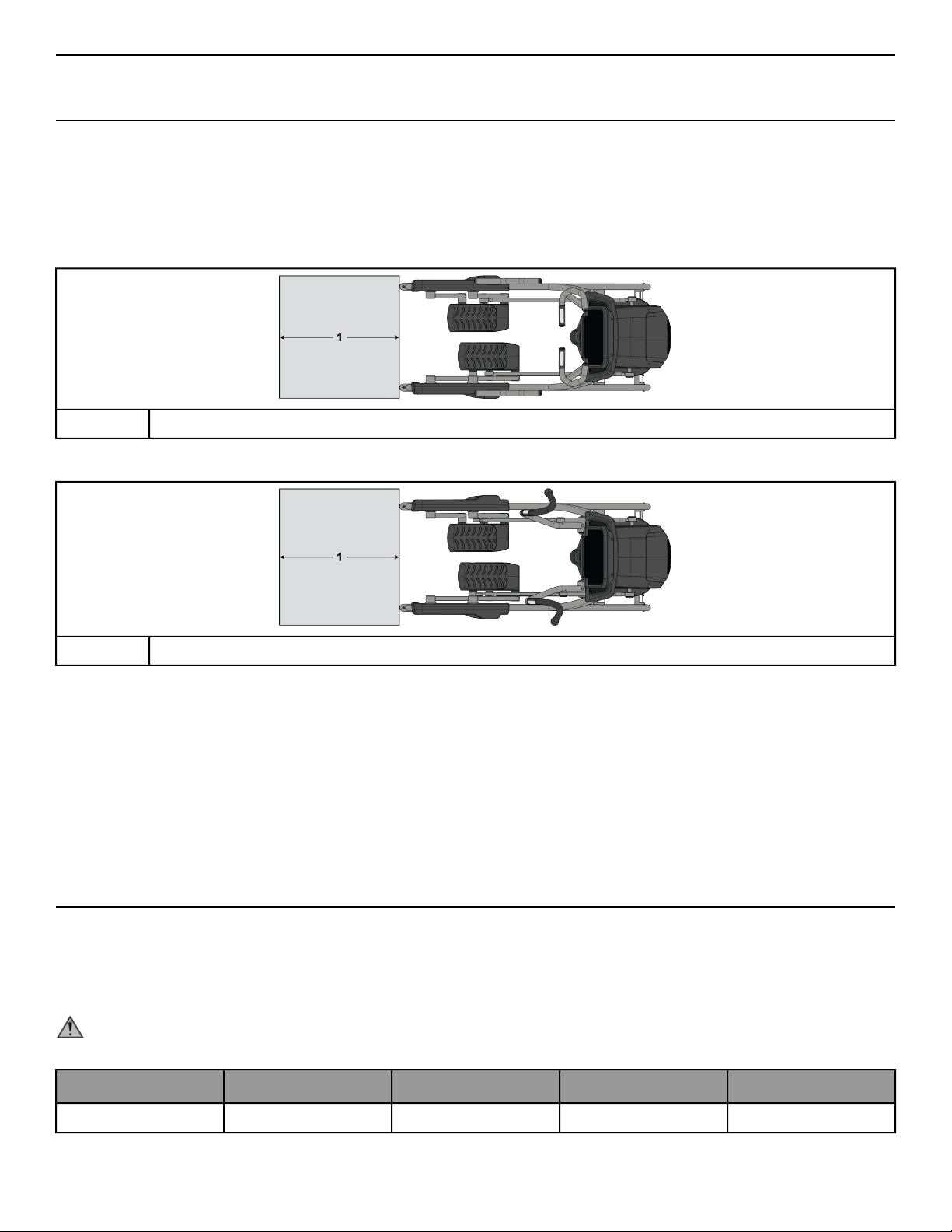
• Free area for access to unit and emergency dismount. Minimum clearance is 23.6 inches (0.6 meters).
• Adjacent units may share the free area.
Free Area - R Series Lower Body
23.6”, 0.6m
1
Free Area - R Series Total Body
23.6”, 0.6m
1
It is the responsibility of the facility owner/owner of the equipment to ensure that there is appropriate clearance
around each machine to allow for safe use and passage.
In compliance with the ADA (American Disabilities Act) there must be clear floor space of at least 30 by 48 inches
and be served by an accessible route for at least one of each type of exercise equipment. If the clear space is
enclosed on three sides (e.g., by walls or the equipment itself), the clear space must be 36 by 48 inches.
All other machines must have a clear floor space of 23" for all access point on the machine.
The dimensions stated in the assembly instructions of this manual include the maximum foot print (in use)
dimensions.
Minimum clearance of 12” (30 cm) between units for proper wireless heart rate signal operation.
Electrical Power Requirements (Applicable for Units Using External Power Supply)
• Units that are only equipped with the 50L console are self powered.
• Units with the 50L console can be used with an optional 12 VDC external power supply. Use of an attachable
TV requires a 12 VDC external power supply.
• Units with the 70T console are required to use a 24 VDC external power supply.
WARNING: Use only the supplied power brick and line cord. Do not use any modification to connect to a
2-prong outlet. Product must be connected to a properly rated 3-prong outlet.
Output CurrentOutput VoltageFrequencySupply VoltageConsole
3 A or 5 A12 VDC47 - 63 Hz95 - 264 VAC50L
Page 10 of 47
Output CurrentOutput VoltageFrequencySupply VoltageConsole
5 A12 VDC47 - 63 Hz95 - 264 VAC50L with Attachable TV
3.5 A24 VDC47 - 63 Hz95 - 264 VAC70T
Commercial Units Outlet & Breaker (Amps)Outlet Voltage
20 (no more than 10 units per breaker)120 VAC
12 (no more than 10 units per breaker)230 VAC
NOTE: Do not modify the plug provided with this product. If the plug does not fit into an available electrical
outlet, have a proper outlet installed by a qualified electrician.
NOTE: Make sure the power brick cord is securely connectedto thebase unit.A looseconnection mayresult
in the unit not receiving external power.
Install External Power Supply
Two different options exist for the external power supply. The 50L console, a self-powered unit compatible with
a 12 VDC optional power supply for enhanced charging features and the 70T, which requires a 24 VDC power
supply.
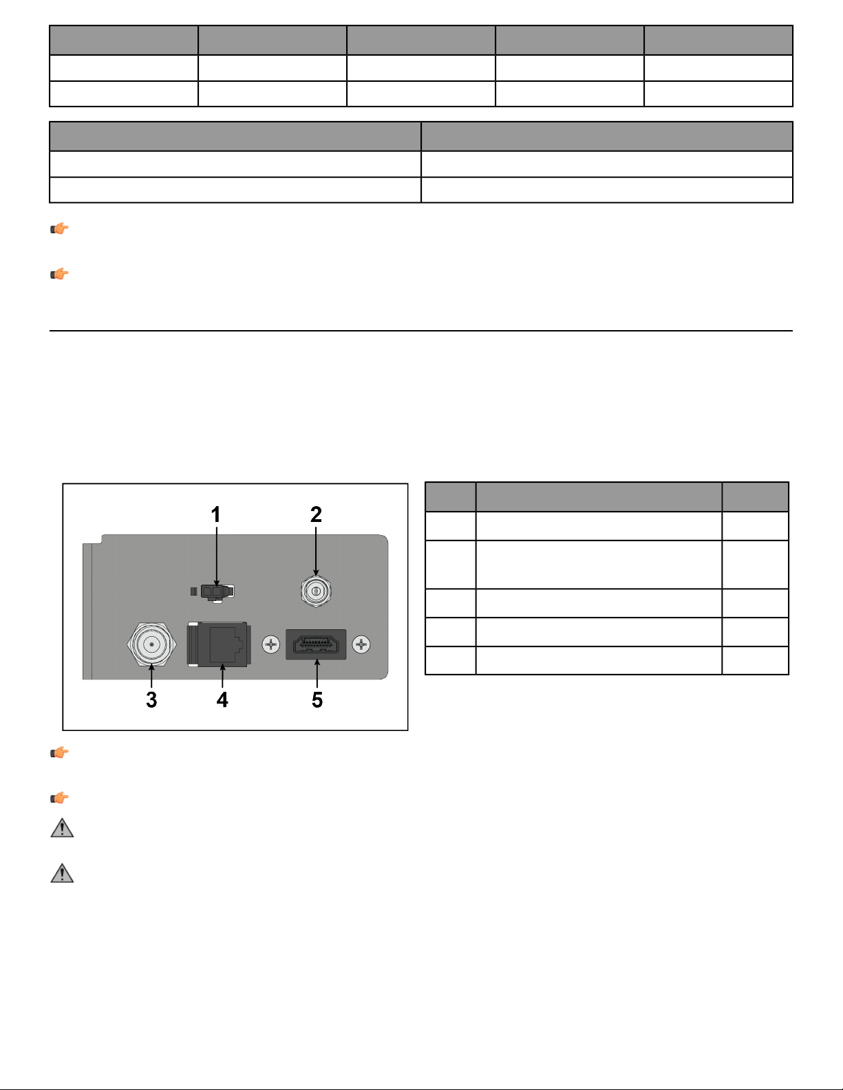
1. Plug in the power to the external power connector on the front end of the unit.
2. Tighten the connector to the unit until its securely in place.
3. Plug the cord into an AC outlet.
QtyDescription
1IR Cable Connector1
1
External Power for Console
Connector
2
1Coax Cable Connector3
1Ethernet Cable Connector4
1HDMI Cable Connector5
NOTE: If the console does not light up, contact Customer Support Service. Use only the power supply
provided in order to ensure against unsafe operation.
NOTE: CSAFE connections must be made at the console only.
CAUTION: Units with the50L console should ONLYuse the 12 VDCpower supply. The 70Tconsole REQUIRES
the 24 VDC power supply. Using a 24 VDC power supply will damage the console.
CAUTION: Connectors should easily fit into the receptacles. Forcing a connection may lead to damage to
the barrel connector and/or receptacle and may void product warranty. If the power supply barrel doesn’t
fit easily into the receptacle then the wrong power supply is being used.
Page 11 of 47

Check for Console Power
The 50L console is powered by a 12V 7AH battery. The 70T console is plug in only using the 24 VDC power supply.
Check the battery by pressing the Go / Green Arrow button. The console should beep and light up. If a prompt
doesn’t appear, mount the unit and begin pedaling. The console should light up and programming a workout
should be possible. Pedal for 10 - 20 minutes at 50 rpm or faster during a workout for optimum battery charging.
The pedal action during workouts keeps the battery charged. Optional external power supply can be used. If the
unit is externally powered, battery maintenance is automatic and pedaling is not required. Use only the power
supply provided by Cybex to insure against unsafe operation.
Cable TV Hook Up
The console can receive both analog and digital signals. CYBEX is not responsible for the installation of CATV
service or components required for the delivery of CATV service. An external TV signal input via a 75-ohm coaxial
cable must be present before TV setup can occur.
Note to the CATV Installer: This reminder is provided to call the CATV system installer’s attention to Article 820-40
of the NEC that provides guidelines for proper grounding and, in particular, specifies that the cable ground shall
be connected to the grounding system of the building as close to the point of cable entry as practical.
Page 12 of 47

Product Overview
Product Features
R Series Lower Body
DescriptionItem
Console1
Accessory Trays2
Contact Heart Rate Sensors3
Cup Holder4
Side Handles5
Leg Levelers6
R Series Total Body
DescriptionItem
Console1
Accessory Trays2
Cup Holder3
Contact Heart Rate Sensors4
Leg Levelers5
Mounting and Dismounting the Arc Trainer
To mount, step one foot at a time atop each of the foot plates. If necessary, stabilize your body by grasping the
frame, the stationary handles (if available), or the moving handles (if available). Be aware that the pedals will begin
to moveas soon as you putweight on them. Thepedals are large enoughto accommodate different foot positions,
however the most common position is with the user’s toes forward underneath the plastic toe cup.
Page 13 of 47

To begin exercise, push down and back into the pedals. Since the Arc Trainer pedals travel back and forth along
an arc (not in a circle or ellipse), there is no ‘forward’ or ‘backward’ motion.
To dismount, slowly bring the pedals to a stop. Grasp the stationary handles or part of the frame to assist in
stepping off the foot plate, back and away from the machine. When stepping back, ensure that you are beyond
and behind the path of motion of the foot plates. Never stand inside of the machine’s footprint, unless standing
atop the foot plates.
How to Use the Arc Trainer
Once standingon the foot plates, begin exercise by pushing downand back on thefoot plates. The user hasseveral
options for hand placement, not all of which are available on each Arc Trainer variant: 1. Stationary handles along
the side of the frame, 2. Stationary handles around the console, 3. Moving handles, or 4. Not holding anything.
These different postures have an influence on the muscles that are utilized and thus, the calories burned during
the exercise. Always be aware of the position of the moving handles, especially if you are not actively grasping
them. These handles move in synchrony with the pedals, so pull on the handle as you are pushing down and back
with your foot. Speed on the Arc Trainer is measured in cadence as steps per minute. The most common cadences
during use are 100-160 steps per minute, although users performing high intensity intervals may routinely exceed
this range.
Page 14 of 47

Assembly
Assembly Procedure - R Series Lower Body
Two people will be required for this procedure.
TIP: Read and understand all instructions thoroughly before assembling this unit. Check all items carefully.
If there is damage, see the Customer Service section of this manual for proper procedure to return, replace,
or reorder parts.
The words "left" and "right" denote the user's orientation.
Verify you have received the correct package
1. Read box label to verify the model number and voltage (optional) match what was ordered.
2. Verify paint color matches what was ordered.
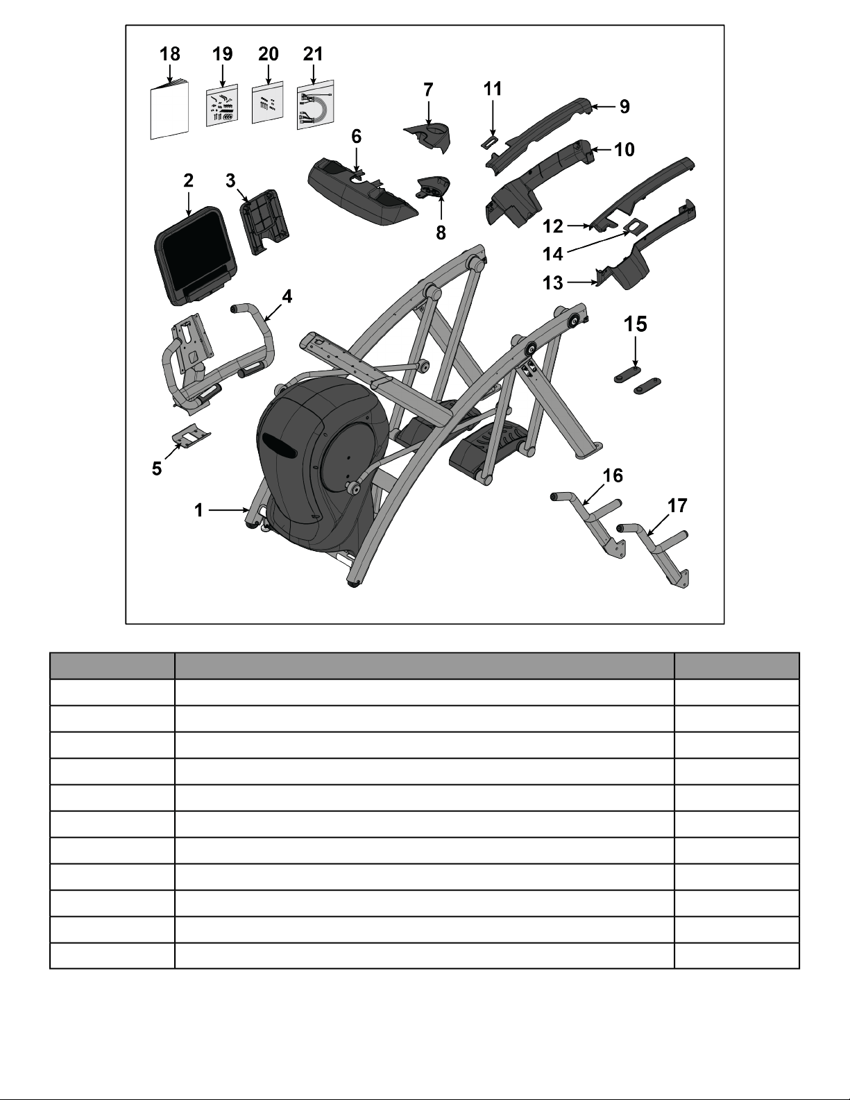
Verify Parts List Shown Below
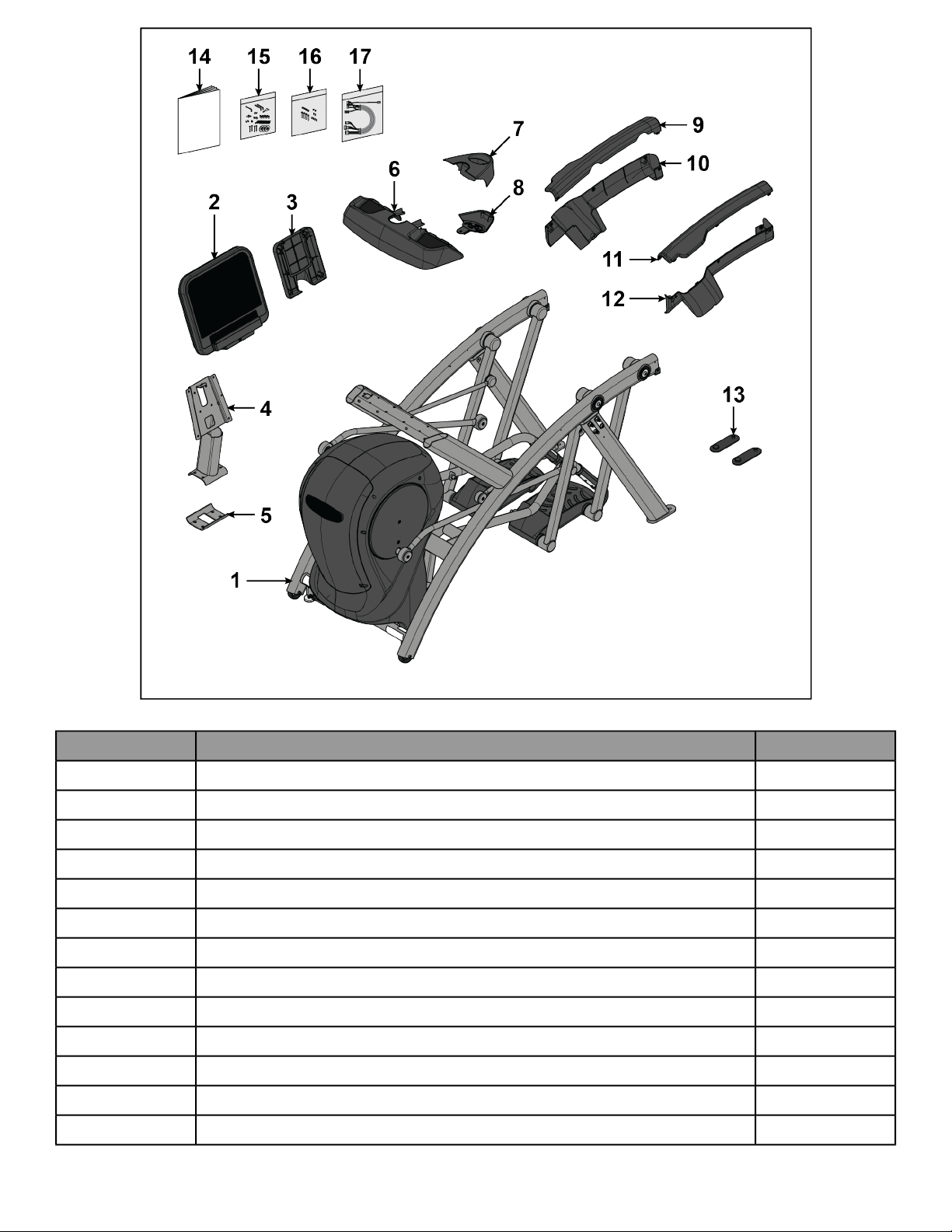
Components
QuantityDescriptionItem
1Base Assembly1
1Console Assembly2
1Cover, Console Back3
1Weldment, Console4
1Bracket, Lower5
1Base, Accessory Tray6
1Cover, Top, Accessory Tray7
1Cover, Bottom, Accessory Tray8
1Cover, Rear, Top, Right9
1Cover, Rear, Lower, Right10
1Gasket, Rear, Right11
1Cover, Rear, Top, Left12
1Cover, Rear, Lower, Left13
1Gasket, Rear, Left14
2Foot Pad15
1Side Handle, Right16
1Side Handle, Left17
1Assembly Instructions18
1Hardware Pack 119
1Hardware Pack 220
1*Wire Harness21
NOTE: *Cabling varies depending on base and console.
Page 15 of 47
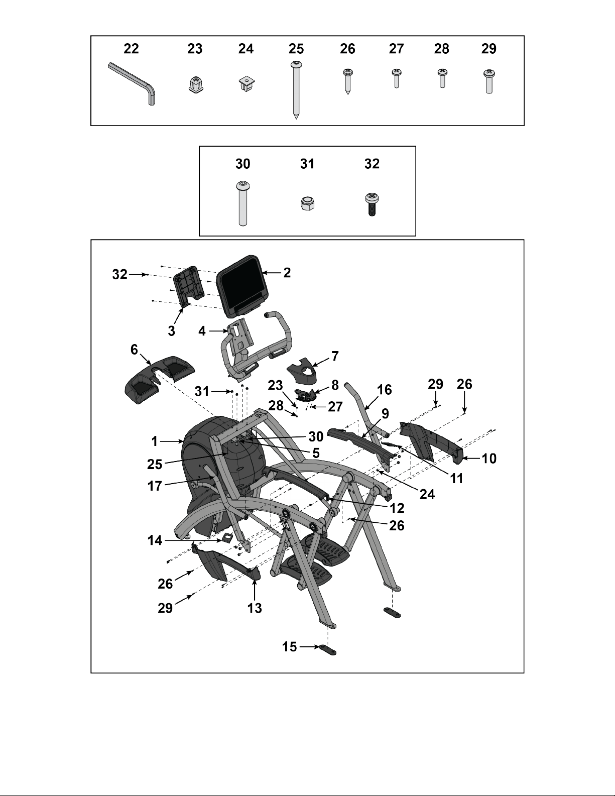
Hardware
QuantityDescriptionItem
17/32” Allen Wrench22
1Grommet, Nylon, Long23
7Grommet, Nylon, Short24
4Screw, Pan Head Phillips, Tap 10-12 x 2"25
7Screw, Pan Head Phillips, M4.2 x 0.7 x 1926
2Screw, Pan Head Phillips, 6 x .50”27
3Screw, Pan Head Phillips, 8-16 x .50”28
11Screw, Pan Head Phillips, 10-24 x .75"29
4Screw, Socket Head, .375-16 x 2.5"30
4Locknut, .375-16 Nylon31
5Screw, Pan Head Phillips, M5 x 0.8 x 1432
Page 16 of 47
Hardware Pack 1
Hardware Pack 2
Tools Required
• Phillips screwdriver
• Stubby Phillips screwdriver
• 6 mm Allen wrench
Page 17 of 47
• 7 mm Allen wrench
• 7/32” Allen wrench
• 17 mm Open end wrench
• 1/2” Open end wrench
• 9/16” Open end wrench
Lift and Move Unit
1. Remove lag bolts and shipping supports. Keep package material on linkage arms at this time. This will protect
the paint from scratching during assembly.
2. Grasp each rear support leg firmly and lift with one person on each side.
3. Lift the lower rear support legs so the front transport wheels are able to roll on floor.
Use proper lifting methods.
4. Move unit to intended location.
5. Lower rear support legs.
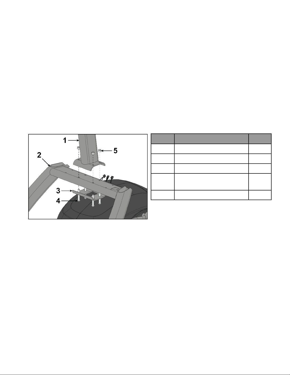
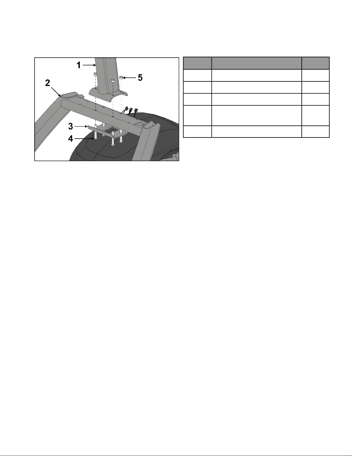
Install Console Weldment
1. Place console weldment into position on frame.
QtyDescriptionItem
1Weldment, Console1
1Frame2
1Bracket, Lower3
4
Screw, Socket Head, .375-16 x
2.5"
4
4Locknut, 375-16 Nylon5
2. Insert (from underneath) four bolts and lower bracket into frame and console weldment.
3. Thread four locknuts onto bolts by hand.
4. Tighten four bolts and locknuts with a 7/32” Allen wrench and a 9/16” open-end wrench.
Page 18 of 47
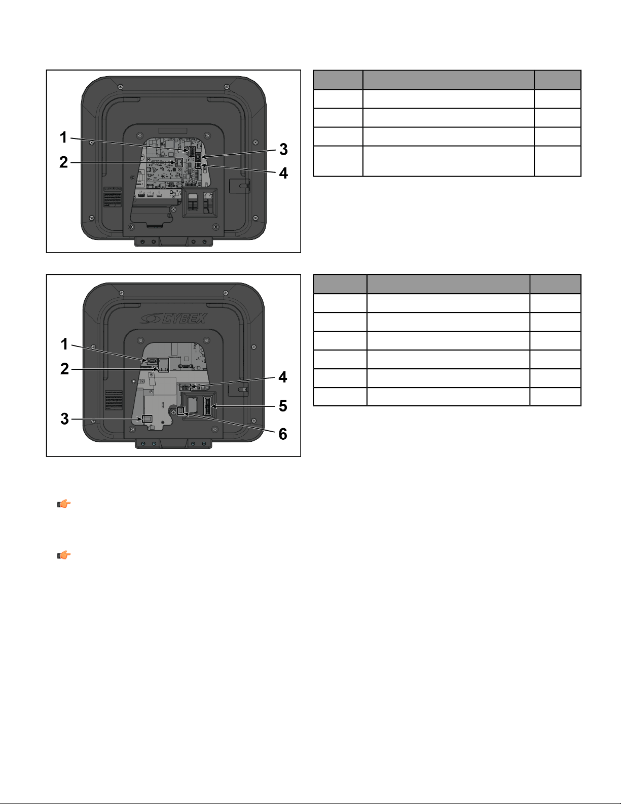
Install Cables to Console
Plug the console cables into the console.
50L Console
QtyDescriptionItem
1Cable, Console to Base Power1
1Cable, Lifepulse2
1Cable, Base Signal3
1
Cable, Heart Rate and Keypad
Switches
4
70T Console
QtyDescriptionItem
1Cable, HDMI1
1Cable, Ethernet2
1Cable, Coax3
1Cable, External Power4
1Cable, PCB to Console Power5
1Cable, IR6
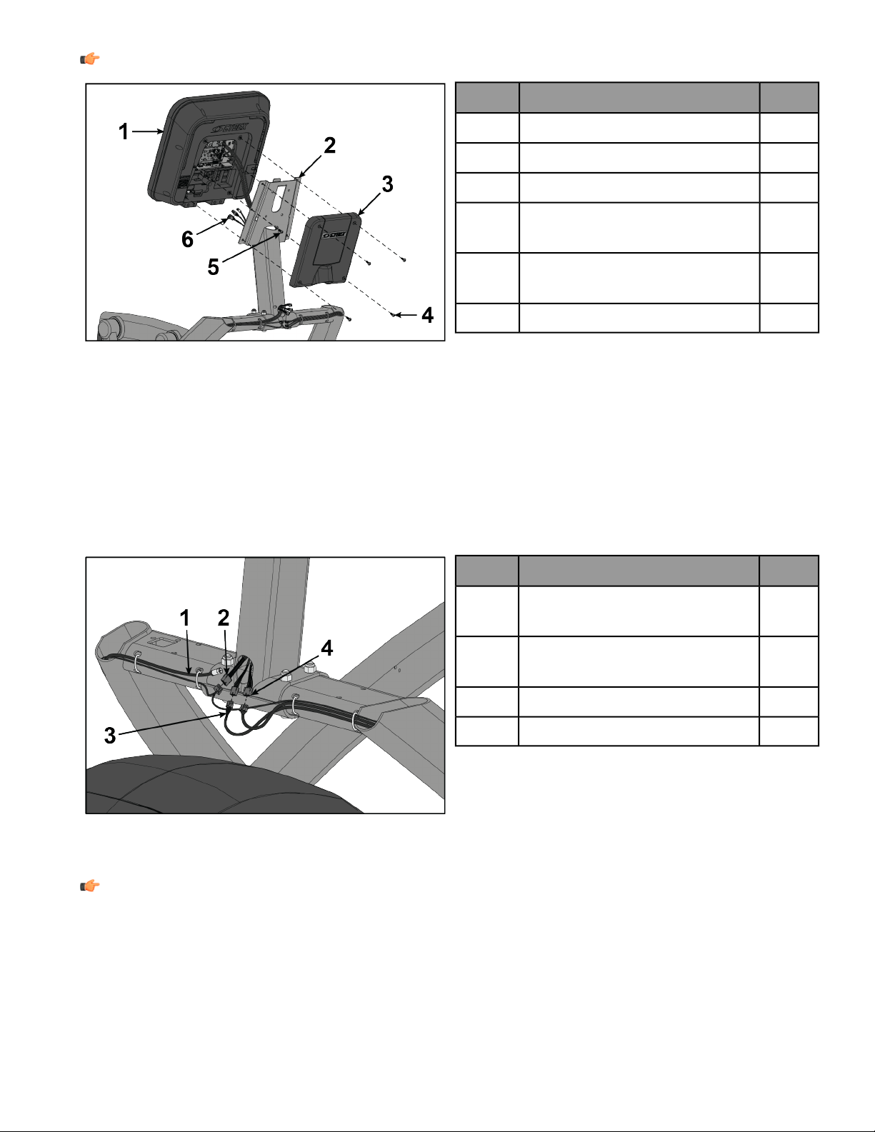
Install Console to Console Weldment
1. Route media cables from frame up through hole at base of console weldment.
NOTE: Media cables for Basic Cabling package include a coax cable. Media cablesfor Advanced Cabling
package include HDMI, ethernet, IR, and coax cables.
2. Connect media cables to console.
NOTE: The 50L Console does not receive a coax cable. The coax cable from the Basic Cabling package
goes to an attachable TV.
3. Insert cables from console into top of console weldment.
Page 19 of 47

4. Place console into position on console weldment.
NOTE: Do not pinch cables while lowering the console.
QtyDescriptionItem
1Console Assembly1
1Weldment, Console2
1Cover, Console Back3
4
Screw, Pan Head Phillips, M5 x 0.8
x 14
4
1
Grounding Screw, Pan Head
Phillips, M5 x 0.8 x 14
5
Media Cables6
5. Exit cables from hole at base of console weldment.
6. Install grounding screw securing console assembly to console weldment using a Phillips screwdriver.
7. Install screws securing console assembly and console back cover to console weldment using a Phillips
screwdriver.
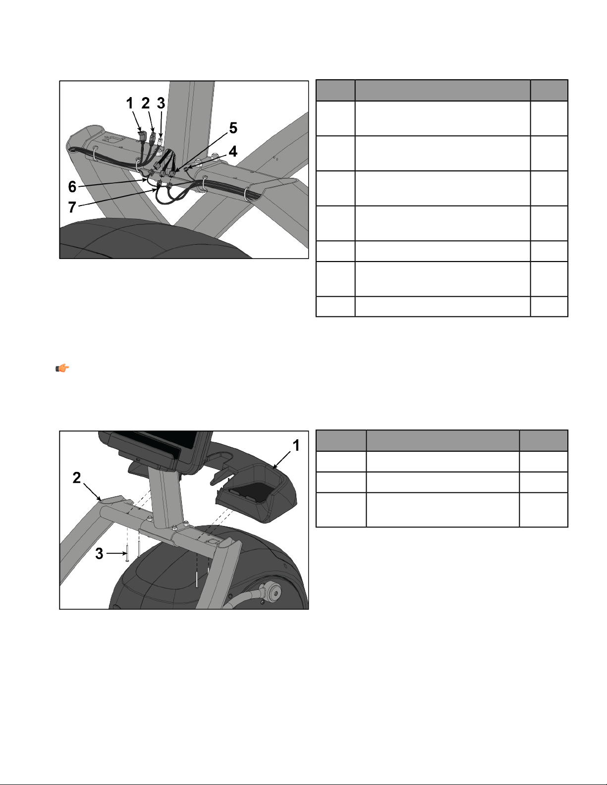
Install Console Cables to Base (Basic Cabling)
This procedure applies to the Basic Cabling option.
1. Plug upper display cable into lower display cable.
QtyDescriptionItem
1
Cable, Coax
(previously routed to console)
1
1
Cable, Heart Rate and Keypad
Switches
2
1Cable, Base Signal3
1Cable, Console to Base Power4
2. Plug upper heart rate cable into lower heart rate cable.
3. Plug console power cable connectors into each other.
NOTE: Console power cables must be connected last.
Page 20 of 47
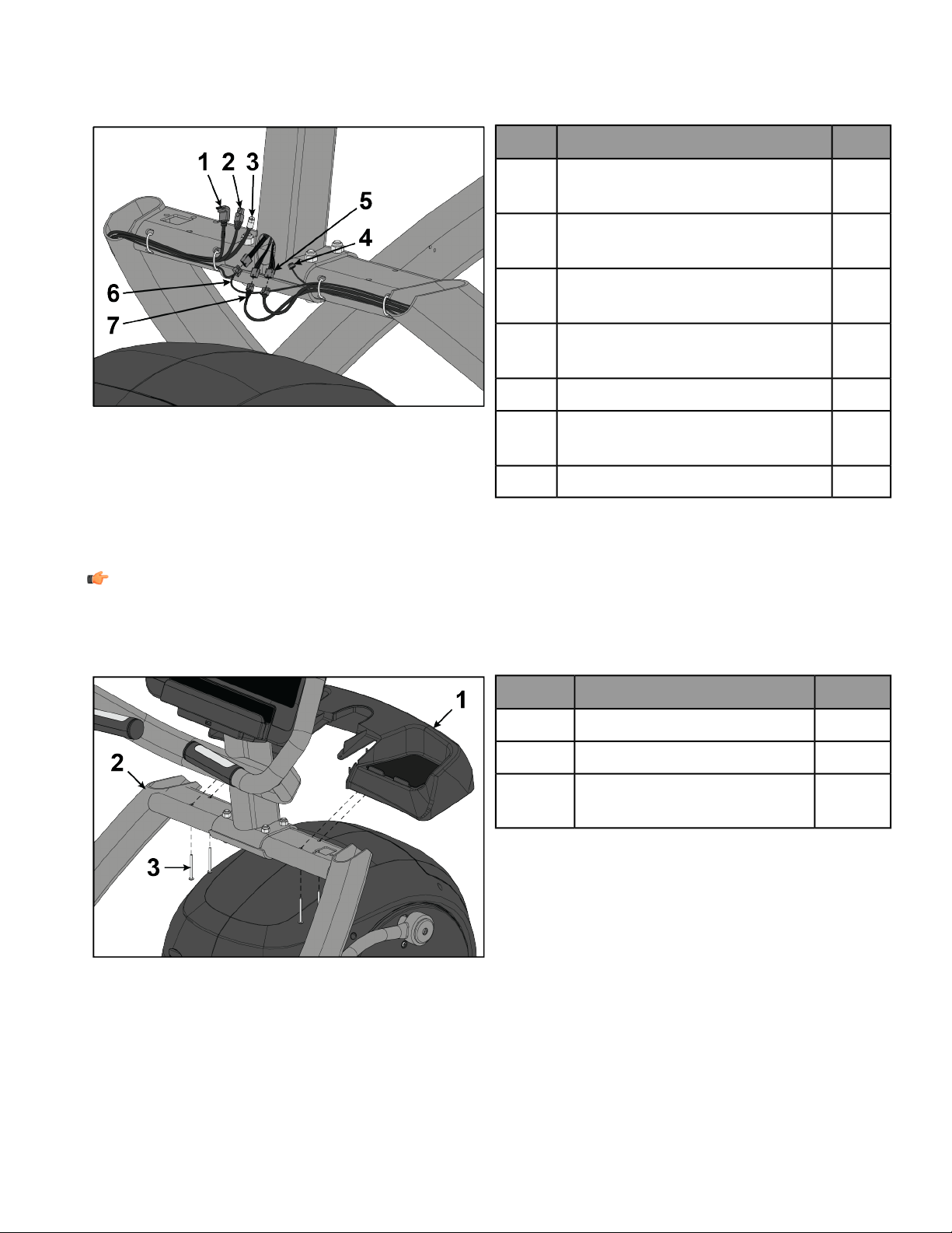
Install Console Cables to Base (Advanced Cabling)
This procedure applies to the Advanced Cabling option.
1. Plug upper display cable into lower display cable.
QtyDescriptionItem
1
Cable, HDMI
(previously routed to console)
1
1
Cable, Ethernet
(previously routed to console)
2
1
Cable, Coax
(previously routed to console)
3
1
Cable, IR
(previously routed to console)
4
1Cable, Console to Base Power5
1
Cable, Heart Rate and Keypad
Switches
6
1Cable, Base Signal7
2. Plug upper heart rate cable into lower heart rate cable.
3. Plug console power cable connectors into each other.
NOTE: Console power cables must be connected last.
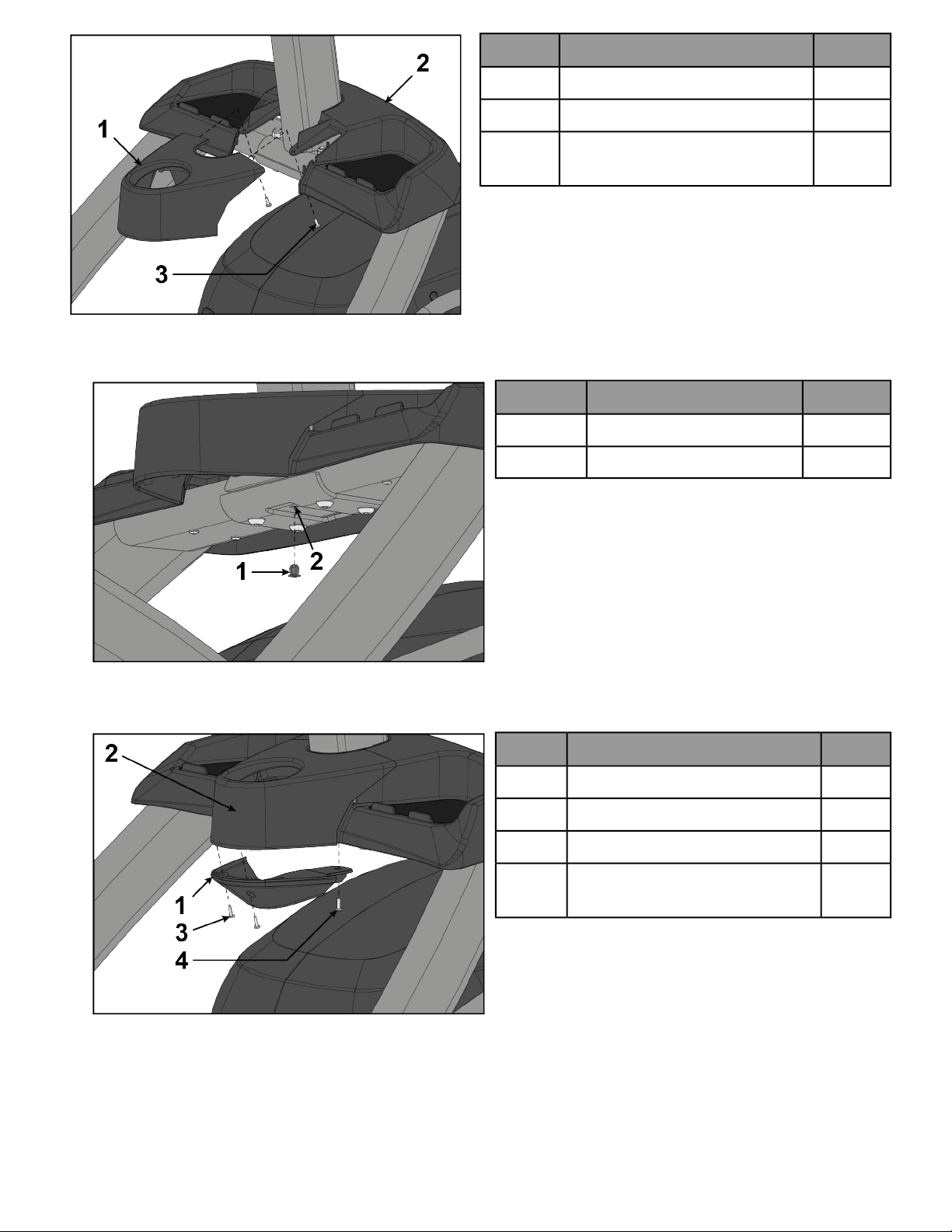
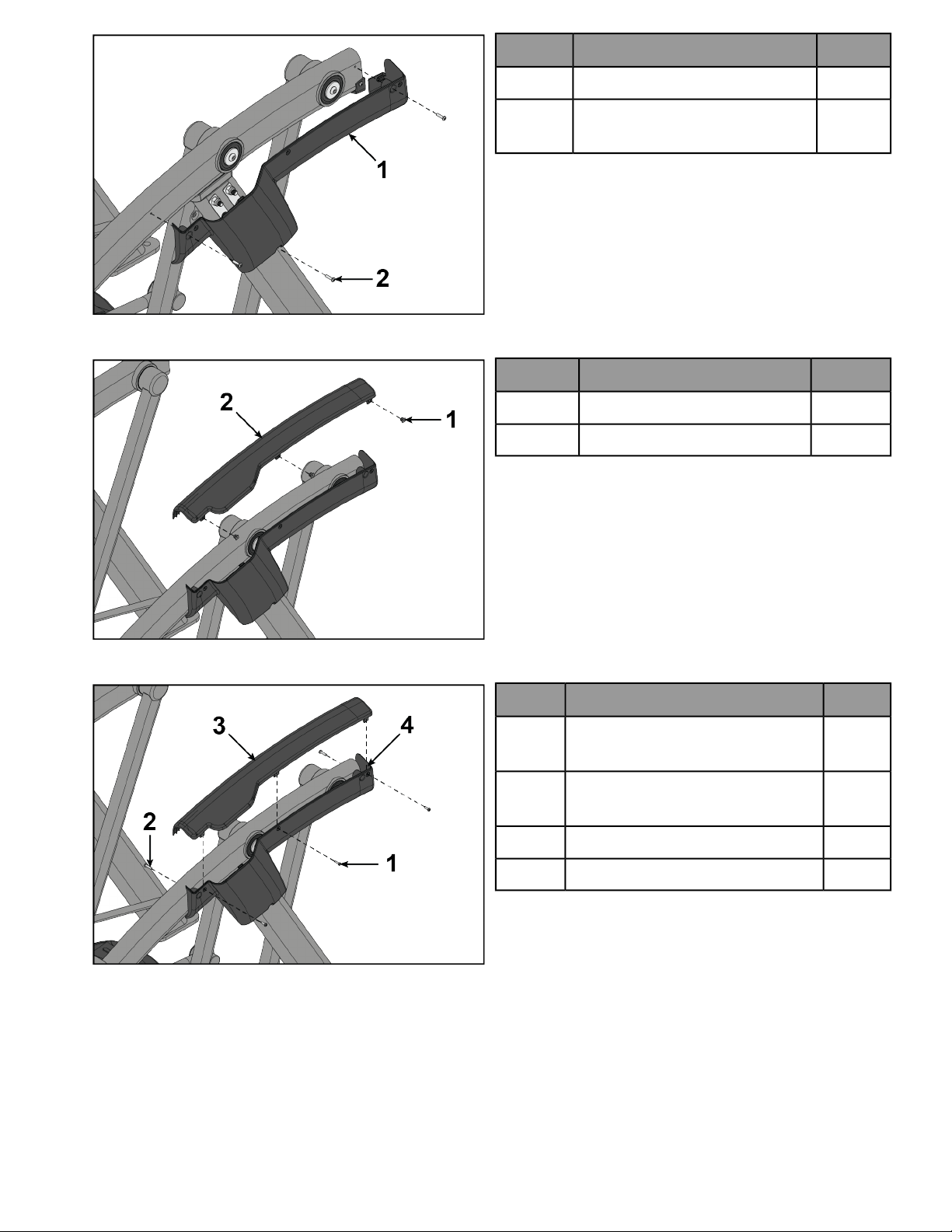
Install Accessory Tray Base
Install screws securing accessory tray base to frame using a Phillips screwdriver.
QtyDescriptionItem
1Accessory Tray Base1
1Frame2
4
Screw, Pan Head Phillips, Tap
10-12 x 2"
3
Install Accessory Tray Top
Install screws securing accessory tray top to accessory tray base using a stubby Phillips screwdriver.
Page 21 of 47
Qty.DescriptionItem
1Accessory Tray Top1
1Accessory Tray Base2
2
Screw, Pan Head Phillips, 8-16 x
.50"
3
Install Accessory Tray Bottom
1. Install the grommet to the frame.
Qty.DescriptionItem
1Grommet, Nylon, Long1
1Frame2
2. Install screws securing the accessory tray bottom to the accessory tray top using a Phillips screwdriver.
3. Install screw securing the accessory tray bottom to the frame using a Phillips screwdriver.
Qty.DescriptionItem
1Accessory Tray Bottom1
1Accessory Tray Top2
2Screw, Pan Head Phillips, 6 x .50"3
1
Screw, Pan Head Phillips, 8-16 x
.50"
4
Install Side Handles
1. Remove three locknuts from left support leg using 17mm open-end wrench and 6mm Allen wrench. Keep the
two spacers in place.
Page 22 of 47
QtyDescriptionItem
3Locknut, M10 x 1.501
2Spacer2
1Side Handle, Left3
2. Install the left side handle and three locknuts using 17mm open-end wrench and 6mm Allen wrench. Ensure
upper roll pin enters hole in frame.
3. Install screws securing left lower rear cover to frame using a Phillips screwdriver.
QtyDescriptionItem
1Cover, Rear, Lower, Left1
3
Screw, Pan Head Phillips, 10-24
x .75"
2
4. Install grommets to left top rear cover.
QtyDescriptionItem
3Grommet, Nylon, Short1
1Cover, Rear, Top, Left2
Page 23 of 47
5. Install screws into grommets securing left lower rear cover to left top rear cover using a Phillips screwdriver.
QtyDescriptionItem
3
Screw, Pan Head Phillips, M4.2 x
0.7 x 19
1
2
Screw, Pan Head Phillips, 10-24 x
.75"
2
1Cover, Rear, Top, Left3
1Cover, Rear, Lower, Left4
6. Install screws securing left top rear cover to frame using a Phillips screwdriver.
7. Open gasket and install around left side handle. Press gasket down onto left lower rear cover.
QtyDescriptionItem
1Gasket1
1Side Handle, Left2
1Cover, Rear, Lower, Left3
8. Repeat steps 1 through 7 for the right side.
Install Foot Pads
Have one person lift the unit while a second person places a foot pad under each of the two back feet.
NOTE: Cybex requires that foot pads be installed to prevent rocking.
QtyDescriptionItem
2Foot Pads1
Page 24 of 47
Visually Inspect Unit
1. Remove any packing material from unit.
2. Examine the unit to ensure that the assembly is correct and complete.
Level Unit
This procedure will level the unit by evenly adjusting the weight on the rear feet. Leveling the unit will eliminate
rocking during use.
NOTE: References to left and right are from the users perspective during use.
1. Verify foot plates are completely stopped.
2. Grasp one of the rear covers and slowly lift the rear foot off the floor. Lower rear foot to the floor.
Qty.DescriptionItem
2Rear Cover1
1Left Rear Foot2
1Right Rear Foot3
Lift Here4
3. Grasp the other rear cover and slowly lift the rear foot off the floor. Lower rear foot to the floor.
Make note of either rear foot lifting off the floor easier than the other.
If both rear feet lift off the floor evenly, secure both leveling foot jam nuts against the frame post using a 9/16”
open-end wrench. Unit is leveled.
Left leveling foot shown
Qty.DescriptionItem
1Frame Post1
1Jam Nut2
1Leveling Foot3
Turn Counter-Clockwise to
Secure
4
Page 25 of 47
4. Adjust the weight of the rear feet using a 1/2” open-end wrench.
• If the left rear foot lifts up easier, Adjust the right leveling foot nut down.
• If the right rear foot lifts up easier, Adjust the left leveling foot nut down.
Left leveling foot shown
Qty.DescriptionItem
1Frame Post1
1Leveling Foot Nut2
1Leveling Foot3
Turn Clockwise to Adjust
Leveling Foot Down
4
5. Test the unit again for uneven weight on the rear feet. Adjust leveling foot nuts until each rear foot lifts with
even force.
6. Secure both jam nuts using a 9/16” open-end wrench. Unit is leveled.
Page 26 of 47

Assembly Procedure - R Series Total Body
Two people will be required for this procedure.
TIP: Read and understand all instructions thoroughly before assembling this unit. Check all items carefully.
If there is damage, see the Customer Service section of this manual for proper procedure to return, replace,
or reorder parts.
The words "left" and "right" denote the user's orientation.
Verify you have received the correct package
1. Read box label to verify the model number and voltage (optional) match what was ordered.
2. Verify paint color matches what was ordered.
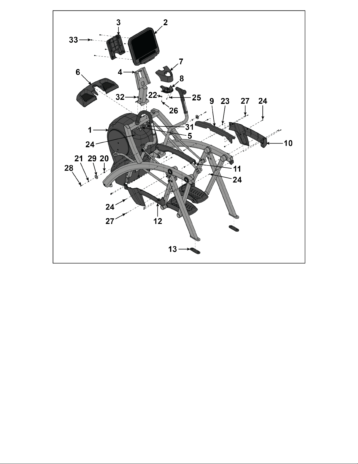
Verify Parts List Shown Below
Components
QuantityDescriptionItem
1Base Assembly1
1Console Assembly2
1Cover, Console Back3
1Weldment, Console4
1Bracket, Lower5
1Base, Accessory Tray6
1Cover, Top, Accessory Tray7
1Cover, Bottom, Accessory Tray8
1Cover, Rear, Top, Right9
1Cover, Rear, Lower, Right10
1Cover, Rear, Top, Left11
1Cover, Rear, Lower, Left12
2Foot Pad13
1Assembly Instructions14
1Hardware Pack 115
1Hardware Pack 216
1*Wire Harness17
NOTE: *Cabling varies depending on base and console.
Page 27 of 47
Hardware
QuantityDescriptionItem
13/16” Allen Wrench18
27/32” Allen Wrench19
2Flange Spacer20
2Washer, Flat .281 ID x .500 OD x .062”21
1Grommet, Nylon, Long22
7Grommet, Nylon, Short23
4Screw, Pan Head Phillips, Tap 10-12 x 2"24
7Screw, Pan Head Phillips, M4.2 x 0.7 x 1925
2Screw, Pan Head Phillips, 6 x .50”26
3Screw, Pan Head Phillips, 8-16 x .50”27
11Screw, Pan Head Phillips, 10-24 x .75"28
2Screw, Socket Head, .250-20 UNC-3A SS29
3Linkage Rod Cap 2.00 OD (1 extra)30
Page 28 of 47
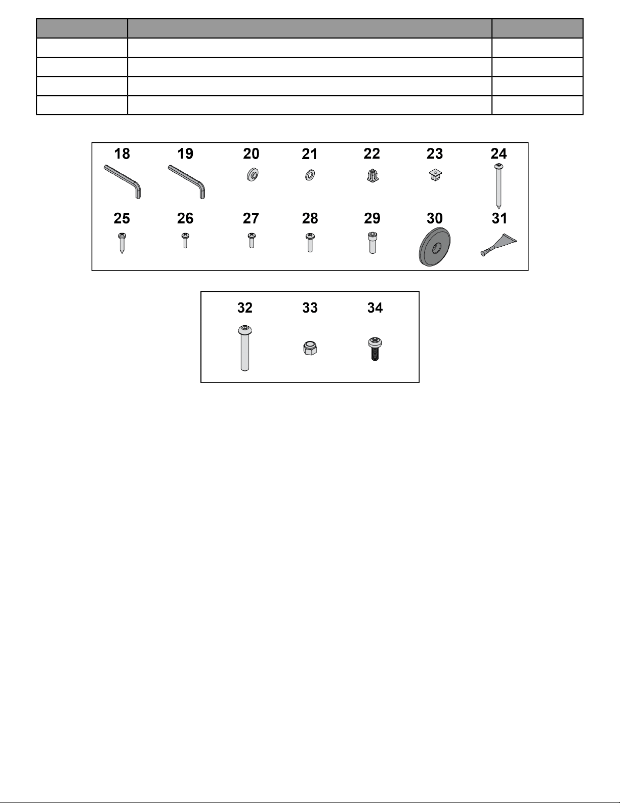
QuantityDescriptionItem
1Loctite #24231
4Screw, Socket Head, .375-16 x 2.5"32
4Locknut, .375-16 Nylon33
5Screw, Pan Head Phillips, M5 x 0.8 x 1434
Hardware Pack 1
Hardware Pack 2
Page 29 of 47
Tools Required
• Phillips screwdriver
• Stubby Phillips screwdriver
• 6 mm Allen wrench
• 7 mm Allen wrench
• 3/16” Allen wrench
• 7/32” Allen wrench (2)
• 17 mm Open end wrench
• 1/2” Open end wrench
• 9/16” Open end wrench
Lift and Move Unit
1. Remove lag bolts and shipping supports. Keep package material on linkage arms at this time. This will protect
the paint from scratching during assembly.
2. Grasp each rear support leg firmly and lift with one person on each side.
3. Lift the lower rear support legs so the front transport wheels are able to roll on floor.
Use proper lifting methods.
Page 30 of 47
4. Move unit to intended location.
5. Lower rear support legs.
Install Console Weldment
1. Place console weldment into position on frame.
QtyDescriptionItem
1Weldment, Console1
1Frame2
1Bracket, Lower3
4
Screw, Socket Head, .375-16 x
2.5"
4
4Locknut, 375-16 Nylon5
2. Insert (from underneath) four bolts and lower bracket into frame and console weldment.
3. Thread four locknuts onto bolts by hand.
4. Tighten four bolts and locknuts with a 7/32” Allen wrench and a 9/16” open-end wrench.
Page 31 of 47

Install Cables to Console
Plug the console cables into the console.
50L Console
QtyDescriptionItem
1Cable, Console to Base Power1
1Cable, Lifepulse2
1Cable, Base Signal3
1
Cable, Heart Rate and Keypad
Switches
4
70T Console
QtyDescriptionItem
1Cable, HDMI1
1Cable, Ethernet2
1Cable, Coax3
1Cable, External Power4
1Cable, PCB to Console Power5
1Cable, IR6
Install Console to Console Weldment
1. Route media cables from frame up through hole at base of console weldment.
NOTE: Media cables for Basic Cabling package include a coax cable. Media cablesfor Advanced Cabling
package include HDMI, ethernet, IR, and coax cables.
2. Connect media cables to console.
NOTE: The 50L Console does not receive a coax cable. The coax cable from the Basic Cabling package
goes to an attachable TV.
3. Insert cables from console into top of console weldment.
Page 32 of 47
4. Place console into position on console weldment.
NOTE: Do not pinch cables while lowering the console.
QtyDescriptionItem
1Console Assembly1
1Weldment, Console2
1Cover, Console Back3
4
Screw, Pan Head Phillips, M5 x 0.8
x 14
4
1
Grounding Screw, Pan Head
Phillips, M5 x 0.8 x 14
5
Media Cables6
5. Exit cables from hole at base of console weldment.
6. Install grounding screw securing console assembly to console weldment using a Phillips screwdriver.
7. Install screws securing console assembly and console back cover to console weldment using a Phillips
screwdriver.
Install Console Cables to Base (Basic Cabling)
This procedure applies to the Basic Cabling option.
1. Plug upper display cable into lower display cable.
QtyDescriptionItem
1
Cable, Coax
(previously routed to console)
1
1
Cable, Heart Rate and Keypad
Switches
2
1Cable, Base Signal3
1Cable, Console to Base Power4
2. Plug upper heart rate cable into lower heart rate cable.
3. Plug console power cable connectors into each other.
NOTE: Console power cables must be connected last.
Page 33 of 47
Install Console Cables to Base (Advanced Cabling)
This procedure applies to the Advanced Cabling option.
1. Plug upper display cable into lower display cable.
QtyDescriptionItem
1
Cable, HDMI
(previously routed to console)
1
1
Cable, Ethernet
(previously routed to console)
2
1
Cable, Coax
(previously routed to console)
3
1
Cable, IR
(previously routed to console)
4
1Cable, Console to Base Power5
1
Cable, Heart Rate and Keypad
Switches
6
1Cable, Base Signal7
2. Plug upper heart rate cable into lower heart rate cable.
3. Plug console power cable connectors into each other.
NOTE: Console power cables must be connected last.
Install Accessory Tray Base
Install screws securing accessory tray base to frame using a Phillips screwdriver.
QtyDescriptionItem
1Accessory Tray Base1
1Frame2
4
Screw, Pan Head Phillips, Tap
10-12 x 2"
3
Install Accessory Tray Top
Install screws securing accessory tray top to accessory tray base using a stubby Phillips screwdriver.
Page 34 of 47

Qty.DescriptionItem
1Accessory Tray Top1
1Accessory Tray Base2
2
Screw, Pan Head Phillips, 8-16 x
.50"
3
Install Accessory Tray Bottom
1. Install the grommet to the frame.
Qty.DescriptionItem
1Grommet, Nylon, Long1
1Frame2
2. Install screws securing the accessory tray bottom to the accessory tray top using a Phillips screwdriver.
3. Install screw securing the accessory tray bottom to the frame using a Phillips screwdriver.
Qty.DescriptionItem
1Accessory Tray Bottom1
1Accessory Tray Top2
2Screw, Pan Head Phillips, 6 x .50"3
1
Screw, Pan Head Phillips, 8-16 x
.50"
4
Install Rear Covers
1. Install screws securing left lower rear cover to frame using a Phillips screwdriver.
Page 35 of 47
QtyDescriptionItem
1Cover, Rear, Lower, Left1
3
Screw, Pan Head Phillips, 10-24
x .75"
2
2. Install grommets to left top rear cover.
QtyDescriptionItem
3Grommet, Nylon, Short1
1Cover, Rear, Top, Left2
3. Install screws into grommets securing left lower rear cover to left top rear cover using a Phillips screwdriver.
QtyDescriptionItem
3
Screw, Pan Head Phillips, M4.2 x
0.7 x 19
1
2
Screw, Pan Head Phillips, 10-24 x
.75"
2
1Cover, Rear, Top, Left3
1Cover, Rear, Lower, Left4
4. Install screws securing left top rear cover to frame using a Phillips screwdriver.
5. Repeat steps 1 through 4 for the right side.
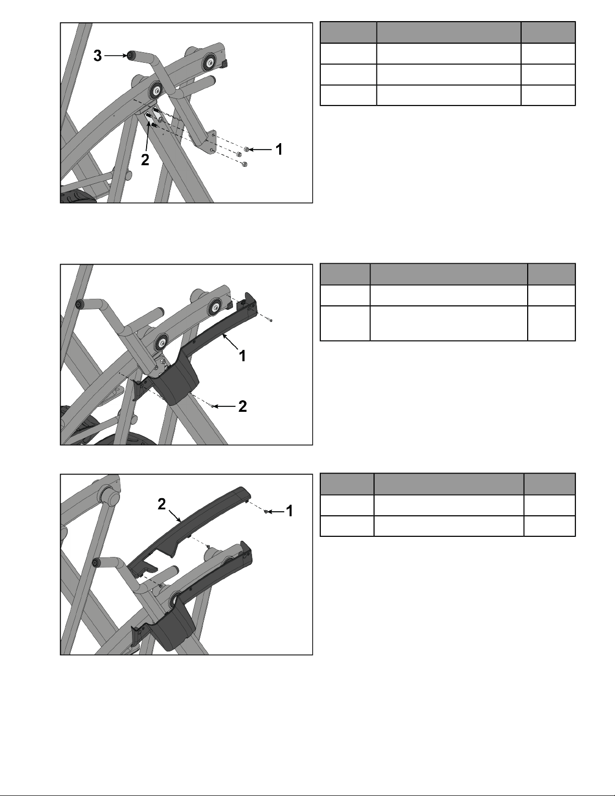
Remove Left and Right Handle Assembly
The left and right handle assemblies are shipped in rotated positions. The handle assemblies must be removed
and rotated 180 degrees for proper setup and assembly.
Page 36 of 47
QtyDescriptionItem
1Handle Assembly, Left1
1Handle Assembly, Right2
1. Remove a screw and washer from the left handle assembly using two 7/32” Allen wrenches.
QtyDescriptionItem
1Screw1
1Washer2
1Handle Assembly, Left3
1Pivot Pin Assembly4
1Loctite #2425
2. Slide pivot pin assembly out and remove left handle assembly.
3. Rotate left handle assembly 180 degrees.
4. Apply Loctite to threads inside the pivot pin and screw.
5. Place left handle assembly in position and slide pivot pin assembly back in place.
6. Install the screw and washer to the left handle assembly using two 7/32” Allen wrenches.
7. Remove a screw and washer from the right handle assembly using two 7/32” Allen wrenches.
QtyDescriptionItem
1Screw1
1Washer2
1Handle Assembly, Right3
1Pivot Pin Assembly4
1Loctite #2425
Page 37 of 47
8. Slide pivot pin assembly out and remove right handle assembly.
9. Rotate right handle assembly 180 degrees.
10. Apply Loctite to threads inside the pivot pin and screw.
11. Place right handle assembly in position and slide pivot pin assembly back in place.
12. Install the screw and washer to the right handle assembly using two 7/32” Allen wrenches.
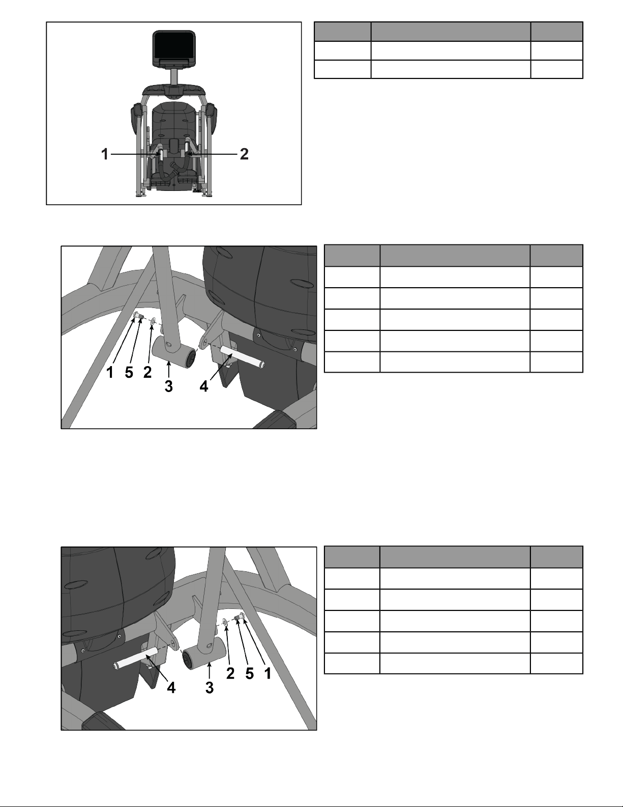
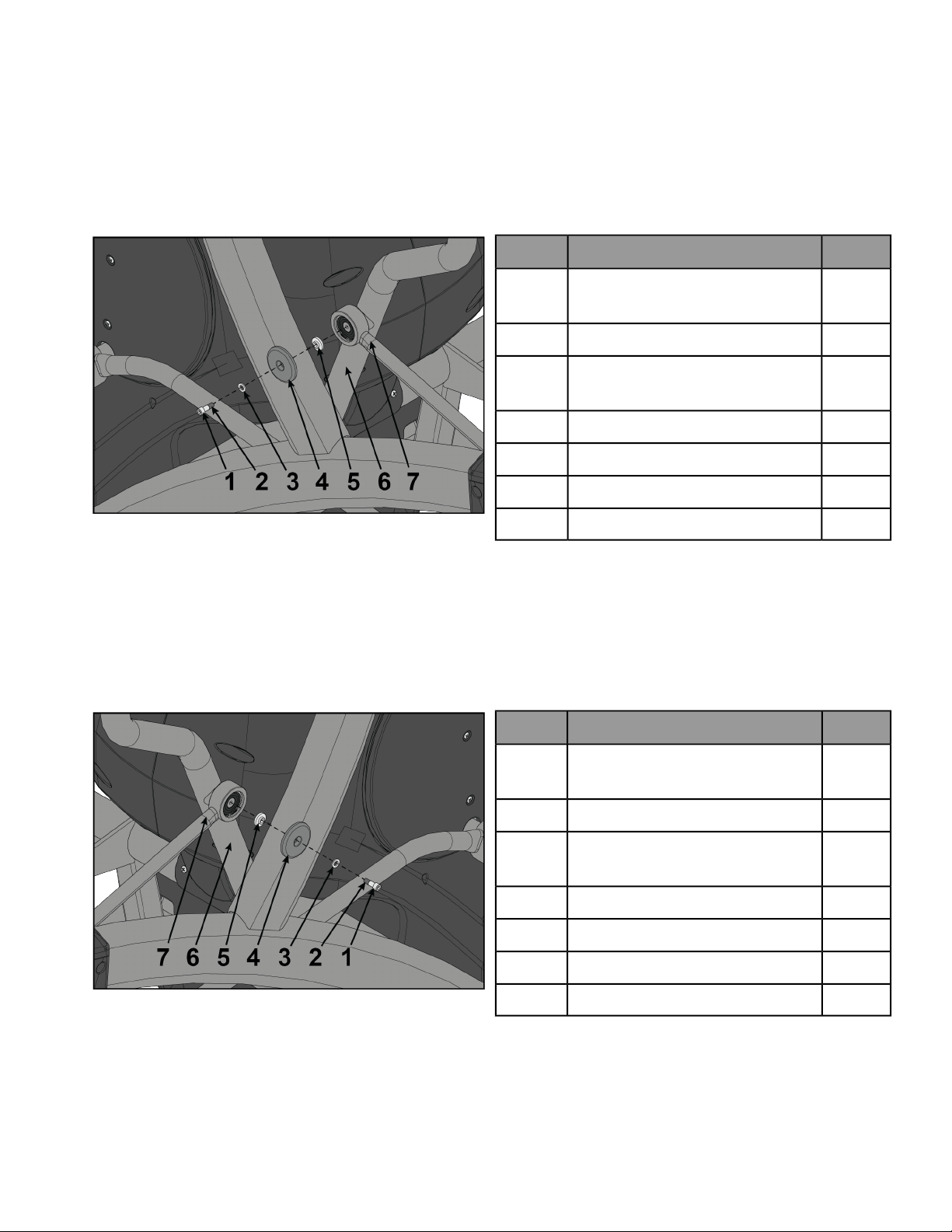
Install Left Linkage Rod
1. Pivot left handle assembly up and slide left linkage rod onto left arm.
QtyDescriptionItem
1
Screw, Socket Head, .250-20
UNC-3A SS
1
1Loctite #2422
1
Washer, Flat, .281 ID x .500 OD x
.062”
3
1Linkage Rod Cap 2.00 OD4
1Flange Spacer5
1Left Arm6
1Left Linkage Rod7
2. Place a drop of Loctite onto the screw.
3. Install the screw, washer, linkage rod cap, and flange spacer using a 3/16” Allen wrench.
4. Tighten screw to a minimum of 90 in-lbs.
Install Right Linkage Rod
1. Pivot right handle assembly up and slide right linkage rod onto right arm.
QtyDescriptionItem
1
Screw, Socket Head, .250-20
UNC-3A SS
1
1Loctite #2422
1
Washer, Flat .281 ID x .500 OD x
.062”
3
1Linkage Rod Cap 2.00 OD4
1Flange Spacer5
1Right Arm6
1Right Linkage Rod7
2. Place a drop of Loctite onto the screw.
3. Install the screw, washer, linkage rod cap, and flange spacer using a 3/16” Allen wrench.
Page 38 of 47
4. Tighten screw to a minimum of 90 in-lbs.
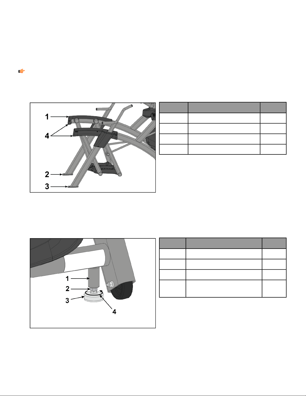
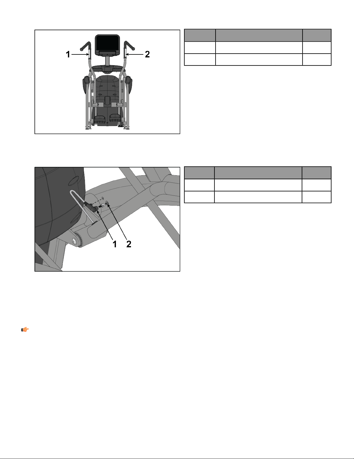
Verify handle assemblies are now installed in the correct position.
QtyDescriptionItem
1Left Handle Assembly1
1Right Handle Assembly2
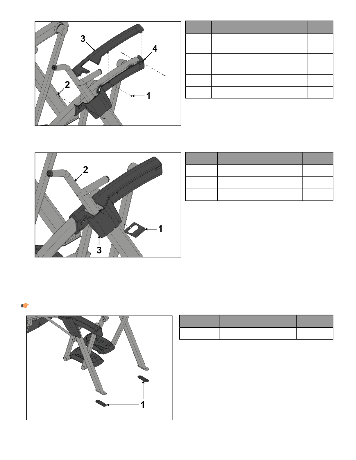
Install Contact Heart Rate Cable
1. Connect handle heart rate cable to frame heart rate cable.
Qty.DescriptionItem
1Heart Rate Cable, Handle1
1Heart Rate Cable, Frame2
2. Press ends of handle heart rate cable into frame.
3. Repeat steps to install heart rate cable on opposite handle.
Install Foot Pads
Have one person lift the unit while a second person places a foot pad under each of the two back feet.
NOTE: Cybex requires that foot pads be installed to prevent rocking.
Page 39 of 47
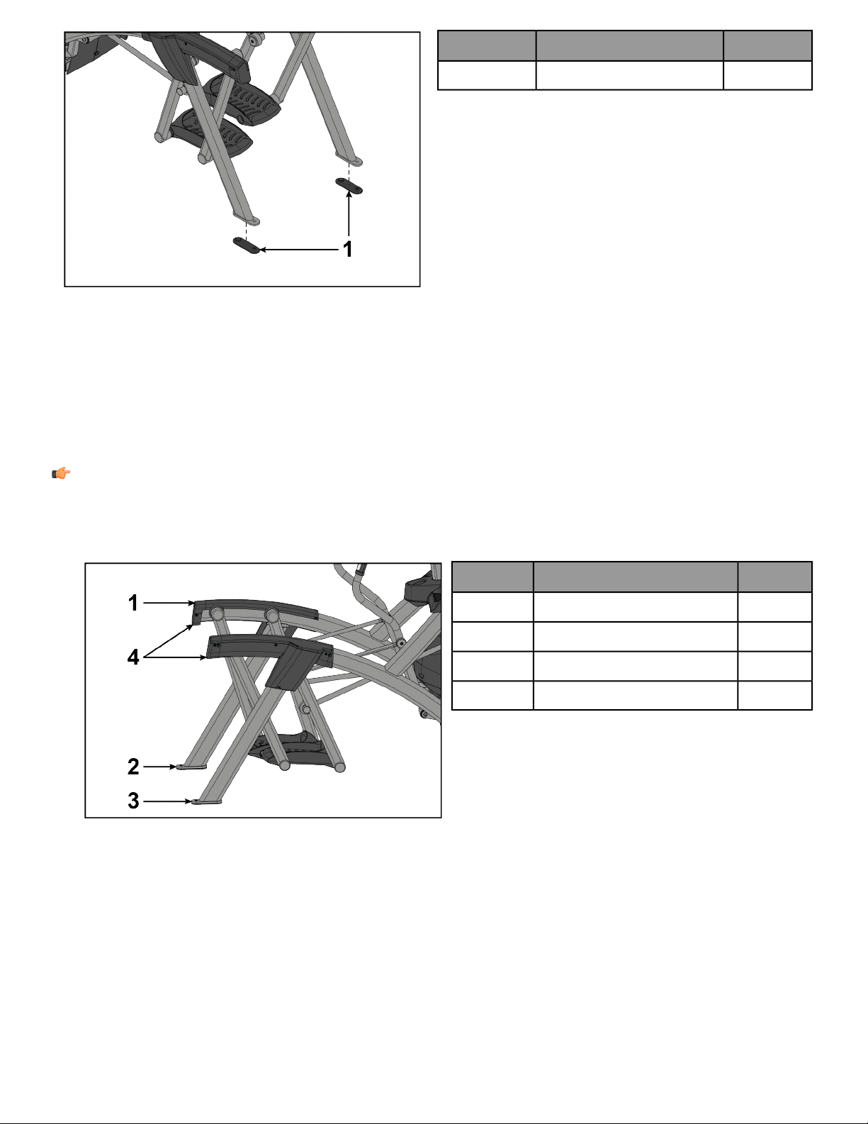
QtyDescriptionItem
2Foot Pads1
Visually Inspect Unit
1. Remove any packing material from unit.
2. Examine the unit to ensure that the assembly is correct and complete.
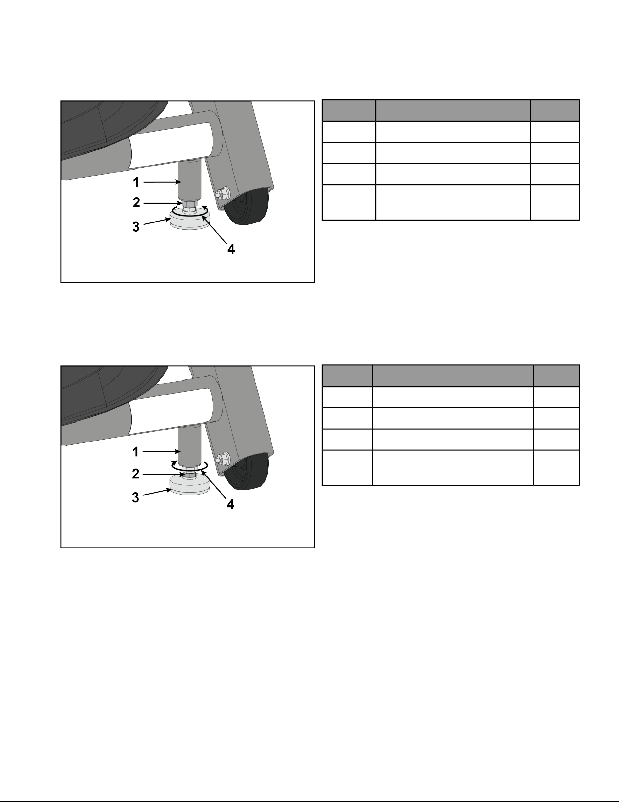
Level Unit
This procedure will level the unit by evenly adjusting the weight on the rear feet. Leveling the unit will eliminate
rocking during use.
NOTE: References to left and right are from the users perspective during use.
1. Verify foot plates are completely stopped.
2. Grasp one of the rear covers and slowly lift the rear foot off the floor. Lower rear foot to the floor.
Qty.DescriptionItem
2Rear Cover1
1Left Rear Foot2
1Right Rear Foot3
Lift Here4
Page 40 of 47
3. Grasp the other rear cover and slowly lift the rear foot off the floor. Lower rear foot to the floor.
Make note of either rear foot lifting off the floor easier than the other.
If both rear feet lift off the floor evenly, secure both leveling foot jam nuts against the frame post using a 9/16”
open-end wrench. Unit is leveled.
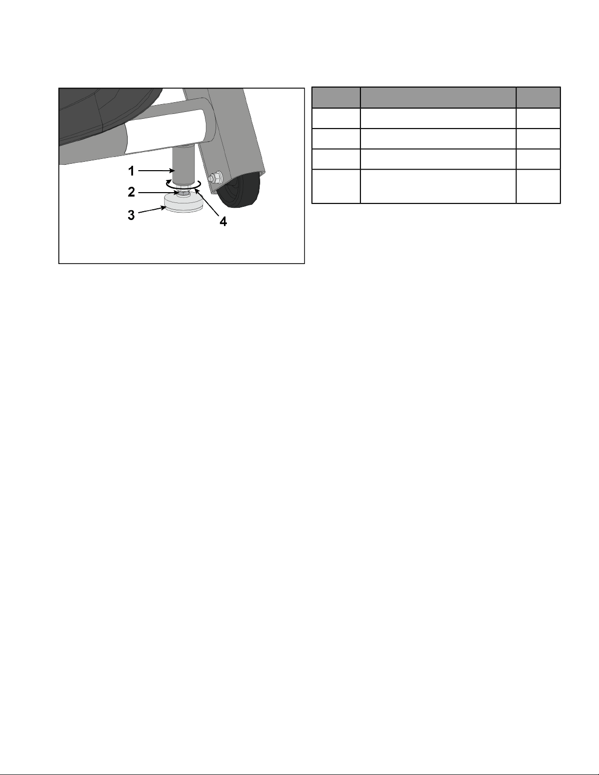
Left leveling foot shown
Qty.DescriptionItem
1Frame Post1
1Jam Nut2
1Leveling Foot3
Turn Counter-Clockwise to
Secure
4
4. Adjust the weight of the rear feet using a 1/2” open-end wrench.
• If the left rear foot lifts up easier, Adjust the right leveling foot nut down.
• If the right rear foot lifts up easier, Adjust the left leveling foot nut down.
Left leveling foot shown
Qty.DescriptionItem
1Frame Post1
1Leveling Foot Nut2
1Leveling Foot3
Turn Clockwise to Adjust
Leveling Foot Down
4
5. Test the unit again for uneven weight on the rear feet. Adjust leveling foot nuts until each rear foot lifts with
even force.
6. Secure both jam nuts using a 9/16” open-end wrench. Unit is leveled.
Page 41 of 47

Service and Technical Data
Preventive Maintenance Tips
CYBEX products are backed by the engineering excellence and reliability of CYBEX and are one of the most rugged
and trouble-free pieces of exercise equipment on the market today.
NOTE: Safety of the equipment can be maintained only if the equipment is examined regularly for damage
or wear. Keep the equipment out of use until defective parts are repaired or replaced. Pay special attention
to parts that are subject to wear, as outlined below.
NOTE: Pour assurer la sécurité du matériel, il convient de l’inspecter régulièrement afin de déceler tout
signe d’usure ou d’endommagement. N’utilisez pas l’appareil avant d’avoir réparé ou remplacé les pièces
défectueuses. Prêtez une attention particulière aux pièces sujettes à usure, tel que décrit ci-dessous.
The following preventive maintenance tips will keep the CYBEX product operating at peak performance:
• Locate the product in a cool, dry place.
• Clean the display console and all exterior surfaces with an approved or compatible cleaner (see CYBEX Approved
Cleaners) and a microfiber cloth.
• Long fingernails may damage or scratch the surface of the console; use the pad of the finger to press the selection
buttons on the console.
• Clean the top surface of the foot plates regularly.
• Clean the housing and moving arms thoroughly on a regular basis.
Approved and Compatible Cleaners
Two preferred cleaners have been approved by reliability experts: PureGreen 24 and Gym Wipes. Both cleaners
will safely and effectively remove dirt, grime and sweat from equipment. PureGreen 24 and the Antibacterial Force
formula of Gym Wipes are both disinfectants that are effective against MRSA and H1N1.
PureGreen 24 is available in a spray which is convenient for gym staff to use. Apply the spray to a microfiber cloth
and wipe down the equipment. Use PureGreen 24 on the equipment for at least 2 minutes for general disinfection
purposes and at least 10 minutes for fungus and viral control.
Gym Wipes are large, durable pre-moistened wipes to use on the equipment before and after workouts. Use Gym
Wipes on the equipment for at least 2 minutes for general disinfection purposes.
Contact Customer Support Services to order these cleaners (1-800-351-3737 or email:
Mild soap and water or a mild non-abrasive household cleanercan also beused to cleanthe display andall exterior
surfaces. Use a soft microfiber cloth only. Apply the cleaner to the microfiber cloth before cleaning. DO NOT use
ammonia oracid based cleaners.DO NOT useabrasive cleaners. DO NOTuse paper towels.DO NOT applycleaners
directly to the equipment surfaces.
Maintenance Schedule
AnnuallyMonthlyWeeklyItem
InspectCleanConsole Overlays
InspectCleanBottle Holders / Accessory Trays
InspectConsole Mounting Bolts
InspectDrive Belts
InspectHardware
Page 42 of 47

AnnuallyMonthlyWeeklyItem
InspectCleanFrames
InspectInspectCleanPlastic Covers
Clean / InspectLifepulse Sensors
InspectCleanFoot Plates
Inspect / AdjustLeg Levelers
Troubleshooting the Polar
®
Heart Rate Chest Strap
Heart rate reading is erratic or absent entirely
Corrective ActionProbable Cause
Wet the belt transmitter electrodes.
Belt transmitter electrodes are not wet enough to pick up accurate
heart rate readings.
Ensure the belt transmitter electrodes are laying flat against the
skin.
Belt transmitter electrodes are not laying flat against the skin.
Wash the belt transmitter with mild soap and water.Belt transmitter needs cleaning.
Setup of the belt transmitter is accomplished by initially bringing
it with in 1 foot of the receiver. The receiver is in the console. After
the heart rate is displayed on the console the range is extended to
3 feet.
Belt transmitter not properly set up.
Contact Customer Support Services for instructions on how to have
the chest strap replaced.
Chest strap battery is depleted.
Abnormally elevated heart rate readings
Corrective ActionProbable Cause
Move the exercise equipment a few inches away from the probable
cause, or move the probable cause a few inches away from the
exercise equipment, until the heart rate readings are accurate.
Electromagnetic interference from television sets and/or antennas.
Electromagnetic interference from cell phones.
Electromagnetic interference from computers.
Electromagnetic interference from cars.
Electromagnetic interference from high voltage power lines.
Electromagnetic interference from motor driven exercise equipment.
Troubleshooting the Lifepulse
™
System Sensors
If the heart rate reading is erratic or missing, do the following:
• Dry the hands if necessary to prevent slipping.
• Apply hands to all eight sensors on user arms or bullhorns.
• Grasp the sensors firmly.
• Apply constant pressure around the sensors.
Drive Belts
Remove Front Access Cover
1. Remove screws securing front access cover using a Phillips screwdriver.
Page 43 of 47
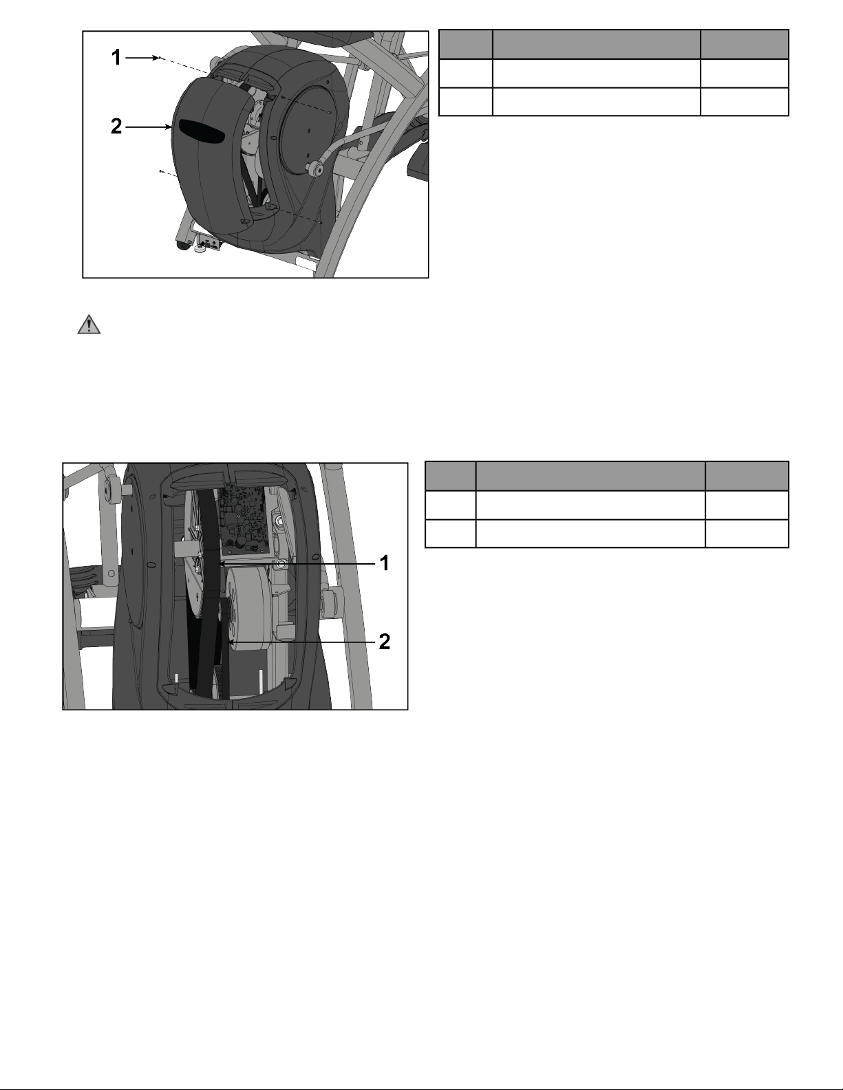
Qty.Description
4Screw1
1Front Access Cover2
2. Remove access cover.
WARNING: Burn hazard. Do not touch flywheel until cool.
Inspect Drive Belts
There are two drive belts that may become loose, worn or cracked.
Unless the belts have been removed and not replaced properly, it is unlikely the belts will come loose or need to
be re-tensioned.
Qty.Description
1Primary Drive Belt1
1Secondary Drive Belt2
If a belt has cracks or appears worn, it must be replaced immediately by a qualified service technician.
Primary Belt
The wider of the two belts. It has grooves that keep it aligned on the large upper pulley.
Secondary Belt
The narrower of the two belts. It has grooves that keep it aligned on the flywheel's drive pulley.
Install Access Cover
Do not over tighten screws.
1. Replace and tighten the two upper screws using a Phillips screwdriver.
2. Replace and tighten the two lower screws using a Phillips screwdriver.
3. Test unit for proper operation.
Page 44 of 47

How to Obtain Product Service
1. Verify the symptom and review the operating instructions. The problem may be unfamiliarity with the product
and its features and workouts.
2. Locate and write down the serial number of the unit which is located on the front of the unit. Write down the
software version if possible.
3. Contact Customer Support Services at http://www.lifefitness.com.
Page 45 of 47

Specifications
R Series - Specifications
R Series Lower Body
EN ISO 20957 Class S (Studio)Classification
AAccuracy
76.25” (194 cm)Assembled Length
36.28” (92 cm)Assembled Width
62.5” (159 cm)Assembled Height
412 lbs. (187 kg.)Product Weight
485-490 lbs. (220-222 kg.) (without console)Shipping Weight
0-20Incline Levels
1-100Resistance Levels
24” (61 cm) fixed lengthStride Length
0 to 900 watts.Resistance Range
400 lbs. (180 kg).Maximum User Weight
100 - 240 VAC~, 50/60 Hz, 2.5A/3.0A, 1-phase.Power Rating
R Series Total Body
EN ISO 20957 Class S (Studio)Classification
AAccuracy
76.25” (194 cm)Assembled Length
36.28” (92 cm)Assembled Width
62.5” (159 cm)Assembled Height
412 lbs. (187 kg.)Product Weight
484-492 lbs. (220-223 kg.) (without console)Shipping Weight
0-20Incline Levels
1-100Resistance Levels
24” (61 cm) fixed lengthStride Length
0 to 900 watts.Resistance Range
400 lbs. (180 kg).Maximum User Weight
100 - 240 VAC~, 50/60 Hz, 2.5A/3.0A, 1-phase.Power Rating
Page 46 of 47


Columbia Center III - 9525 West Bryn Mawr Ave, Rosemont, IL 60018 • 800-351-3737 • 847-288-3700 • FAX 800-216-8893
www.cybexintl.com


