Owners' Guide Ranges
RANGE MAINTENANCE AND CARE
General Cleaning
IMPORTANT: Before cleaning, make sure all controls are off and the oven and cooktop are cool. Always follow label instructions on cleaning products. Soap, water, and a soft cloth or sponge are suggested first, unless otherwise noted.
EXTERIOR PORCELAIN ENAMEL SURFACES (on some models)
Food spills containing acids, such as vinegar and tomato, should be cleaned as soon as the entire range is cool. These spills may affect the finish.
Cleaning Method:
- Glass cleaner, mild liquid cleaner, or nonabrasive scrubbing pad: Gently clean around the model/serial/rating plate because scrubbing may remove numbers.
- Affresh® Kitchen and Appliance Cleaner Part Number W10355010 (not included): See the Quick Start Guide for contact information.
STAINLESS STEEL (on some models)
NOTE: To avoid damage to stainless steel surfaces, do not use soap-filled scouring pads, abrasive cleaners, Cooktop Cleaner, steel-wool pads, gritty washcloths, or abrasive paper towels. Damage may occur to stainless steel surfaces, even with one-time or limited use.
Cleaning Method:
Rub in direction of grain to avoid damaging.
- Affresh® Stainless Steel Cleaner Part Number W10355016 (not included): See the Quick Start Guide for contact information.
METALLIC PAINT (on some models)
Do not use abrasive cleaners, cleaners with bleach, rust removers, ammonia, or sodium hydroxide (lye) because paint surface may stain.
CERAMIC GLASS COOKTOP CLEANING
Cleaning Method:
To avoid damaging the cooktop, do not use steel wool, abrasive powder cleansers, chlorine bleach, rust remover, or ammonia.
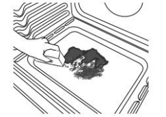
- Remove food/residue with the Cooktop Scraper.
■ For best results, use the Cooktop Scraper while the cooktop is still warm but not hot to the touch. It is recommended to wear an oven mitt while scraping the warm cooktop. ■ Hold the Cooktop Scraper at approximately a 45° angle against the glass surface and scrape the residue. It will be necessary to apply pressure in order to remove the residue.
Allow the cooktop to cool down completely before proceeding to Step 2.
- Apply a few dime-sized drops of Cooktop Cleaner to the affected areas.

■ Rub affresh® Cleaner onto the cooktop surface with the blue Cooktop Cleaning Pad. Some pressure is needed to remove stubborn stains.
■ Allow the cleaner to dry to a white haze before proceeding to Step 3.
- Polish with a clean, dry cloth or a clean, dry paper towel

■ Repeat steps 1 through 3 as necessary for stubborn or burned-on stains.
The Complete Cooktop Cleaner Kit is available for order including the following:
■ Cooktop Scraper
■ Affresh® Cooktop Cleaner
■ Blue Cooktop Cleaning Pads See the Quick Start Guide for ordering information.
COOKTOP CONTROLS
To avoid damage to the cooktop controls, do not use steel wool, abrasive cleansers, or oven cleaner.
To avoid damage, do not soak knobs. When replacing knobs, make sure knobs are in the Off position.
On some models, do not remove seals under knobs.
Cleaning Method:
- Soap and water: Pull knobs straight away from control panel to remove
CONTROL PANEL AND OVEN DOOR EXTERIOR
To avoid damage to the control panel, do not use abrasive cleaners, steel-wool pads, gritty washcloths, or abrasive paper towels.
Cleaning Method:
- Glass cleaner and soft cloth or sponge: Apply glass cleaner to soft cloth or sponge, not directly on panel.
- Affresh® Kitchen and Appliance Cleaner Part Number W10355010 (not included): See the Quick Start Guide for contact information.
OVEN RACKS
Cleaning Method:
- Steel-wool pad
- For racks that have discolored and are harder to slide, a light coating of vegetable oil applied to the rack guides will help them slide
- Dishwasher (steam rack water reservoir only, not racks): Although the water reservoir is durable, it may lose its shine and/or discolor when washed in a dishwasher
STORAGE DRAWER OR WARMING DRAWER (on some models)
Check that storage drawer or warming drawer is cool and empty before cleaning.
Cleaning Method:
OVEN CAVITY
Depending on your model, use AquaLift® Technology or SelfClean cycle regularly to clean oven spills.
Do not use oven cleaners
Food spills should be cleaned when oven cools. At high temperatures, foods react with porcelain. Staining, etching, pitting, or faint white spots can result.
Cleaning Method:
- Clean cycle: See “Clean Cycle” first
Clean Cycle

AquaLift® Technology is an innovative cleaning solution that utilizes heat and water to release baked-on spills from the oven in less than 1 hour. This new cleaning technology is a low-heat, odor-free alternative to traditional self-cleaning options.
Allow the oven to cool to room temperature before using the Clean cycle. If your oven cavity is above 200°F (93°C), it will appear in the display, and the Clean cycle will not be activated until the oven cavity cools down.
To Clean:
- Remove all racks and accessories from the oven cavity, and wipe excess soil. Use a plastic scraper to remove easily removed soils
- Pour distilled or filtered water onto the bottom of the empty oven, and close the oven door.
IMPORTANT: Do not use chemicals or other additives with the water. Do not open the oven door during the Clean cycle. The water on the oven bottom is hot.
- Press CLEAN or AQUALIFT SELF CLEAN and then START on the oven control panel.
- Allow 40 minutes for cleaning and cool down. A beep will sound when the Clean cycle is complete.
- Press CANCEL, CANCEL UPPER or OFF at the end of the cycle. Cancel, Cancel Upper or Off may be pressed at any time to stop the Clean cycle.
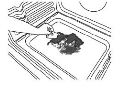
- Remove the residual water and loosened soils with a sponge or cloth immediately after the Clean cycle is complete. Much of the initial 2 cups (16 oz [500 mL]) of water will remain in the oven after the cycle is completed. If additional soils remain, leave a small amount of water in the oven bottom to assist with the cleaning.
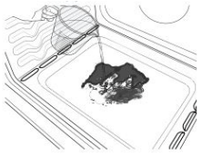
- If any soils remain, remove them with a non-scratch scrubbing sponge or plastic scraper. Additional Clean cycles may be run to help remove the stubborn soils. IMPORTANT: Do not use oven cleaners. The use of chemicals, including commercial oven cleaners or metal scouring pads, may cause permanent damage to the porcelain surface of the oven interior.
NOTES:
- The range should be level to ensure that the entire surface of the bottom of the oven cavity is covered by water at the beginning of the Clean cycle.
- For best results, use distilled or filtered water. Tap water may leave mineral deposits on the oven bottom.
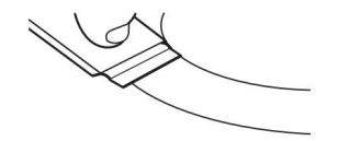
- Before removing the residual water and loosened soils at the end of the Clean cycle, insert a cloth or paper towel between the lower edge of the oven door and the front frame to keep water from spilling onto the front of the range and the floor.
- Soil baked on through several cooking cycles will be more difficult to remove with the Clean cycle.
- Nonabrasive scrub sponges or eraser style cleaning pads (without cleaners) can be effective for cleaning the oven cavity walls, oven door and oven bottom for difficult soils. For best results, moisten the pads and sponges before use.
- Run an additional Clean cycle for stubborn soils
- Affresh® Kitchen Appliance Cleaner and affresh® Cooktop Cleaner may be used to clean the oven bottom, walls, and door when the oven has finished the cycle and returned to room temperature. If affresh® Cooktop Cleaner is used, it is recommended to wipe out the cavity with distilled water as well. Refer to the Quick Start Guide for ordering information.
- Additional AquaLift® Technology Cleaning Kits may be obtained by ordering Part Number W10423113RP. Refer to the Quick Start Guide for ordering information.
Freestanding Electric Range Quick Start Guide
OPERATING INSTRUCTIONS
WARNING: To reduce the risk of fire, electric shock, or injury to persons, read the IMPORTANT SAFETY INSTRUCTIONS, located in your appliance's Owner's Manual, before operating this appliance.
Using Your Oven
Step 1. Select oven function
Step 2. Set the temperature
Step 3. Press Start
Step 4. Place food inside the oven once set temperature is reached. Close the oven door.
Step 5. (Optional) Enter time to cook
Step 6. The Cancel button can be use to cancel the function during or after cook time.
NOTE: For more detailed instructions on specific functions, see the online Control Guide.
Using Your Range
WARNING
Fire Hazard
Turn off all controls when done cooking.
Failure to do so could result in death or fire.
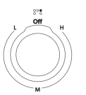
The control knobs can be set to anywhere between “H” and “L.” Push in and turn to setting.
REMEMBER: When range is in use, the entire cooktop area may become hot.
POSITIONING RACKS AND BAKEWARE
IMPORTANT: To avoid permanent damage to the porcelain finish, do not place food or bakeware directly on the oven door or bottom.
Racks
- Position racks before turning on the oven.
- Do not position racks with bakeware on them.
- Make sure racks are level.
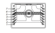
To position a rack, pull it out to the stop position, raise the front edge, and then lift out. Use the following illustration as a guide.
For hamburger patties to have a well-seared exterior and a rare interior, use a flat rack in rack position 7. Side 1 should cook for approximately 2 1/2 to 3 1/2 minutes. Side 2 should cook for approximately 4 to 5 minutes. Expect a moderate degree of smoke when broiling.
BAKING COOKIES AND LAYER CAKES ON 2 RACKS
Baking Layer Cakes
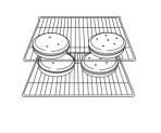
For best results when baking cakes on 2 racks, use racks 2 and 5 with the Bake function. Place the cakes on the racks as shown.
Baking Cookies
For best results baking 2 racks of cookies, use racks 2 and 5 with Convect Bake.
ALUMINUM FOIL
IMPORTANT: To avoid permanent damage to the oven bottom finish, do not line the oven bottom with any type of foil or liner.
For best cooking results, do not cover entire oven rack with foil because air must be able to move freely.
Care must be taken to prevent aluminum foil and meat probes from contacting heating elements.
OVEN VENT
The oven vent releases hot air and moisture from the oven, and should not be blocked or covered. Blocking or covering the oven vent will cause poor air circulation, affecting cooking and cleaning results. Do not set plastics, paper or other items that could melt or burn near the oven vent.
OVEN LIGHT
The oven light is a 40 W halogen bulb. Before replacing, make sure the oven and cooktop are cool and the control knobs are in the Off position.
To Replace:
- Disconnect power.
- Turn the glass bulb cover in the back of the oven counterclockwise to remove.
- Remove bulb from socket.
- Replace bulb, using tissue or wearing cotton gloves to handle bulb. To avoid damage to or decreasing the life of the new bulb, do not touch bulb with bare fingers.
- Replace bulb cover by turning clockwise.
- Reconnect power.
IMPORTANT: Do not use lamps rated higher than 40 W.
SABBATH MODE:
The Sabbath Mode sets the oven to remain on in a bake setting until disabled.
INSTALLATION INSTRUCTIONS
Unpack Range
WARNING
Excessive Weight Hazard
Use two or more people to move and install range.
Failure to do so can result in back or other injury.
- Remove shipping materials, tape and film from range.
- Remove oven racks and parts package from inside oven.
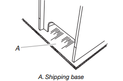
- Do not remove the shipping base at this time.
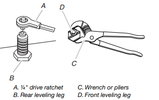
- On Ranges Equipped with a Storage Drawer: Remove the storage drawer. See the “Storage Drawer” section. Use a ¼" drive ratchet to lower the rear leveling legs one-half turn. Use a wrench or pliers to lower front leveling legs one-half turn.
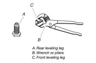
On Ranges Equipped with a Warming Drawer or Premium Storage Drawer: On ranges equipped with a warming drawer or premium storage drawer, the rear leveling legs cannot be accessed by removing the warming drawer or premium storage drawer. It will be necessary to adjust the rear leveling legs from outside the range. Use wrench or pliers to lower the front and rear leveling legs one-half turn.
Install Anti-Tip Bracket
WARNING
Tip Over Hazard
A child or adult can tip the range and be killed.
Install anti-tip bracket to floor or wall per installation instructions.
Slide range back so rear range foot is engaged in the slot of the anti-tip bracket.
Re-engage anti-tip bracket if range is moved.
Do not operate range without anti-tip bracket installed and engaged.
Failure to follow these instructions can result in death or serious burns to children and adults.
- Remove the anti-tip bracket from where it is taped inside the storage drawer or warming drawer.
- Determine which mounting method to use: floor or wall. If you have a stone or masonry floor, you can use the wall mounting method. If you are installing the range in a mobile home, you must secure the range to the floor.
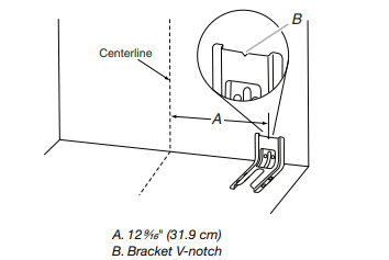
- Determine and mark centerline of the cutout space. The mounting bracket can be installed on either the left-hand side or right-hand side of the cutout. Position mounting bracket against the wall in the cutout so that the V-notch of the bracket is 12⁹⁄₁₆" (31.9 cm) from centerline as shown.
- Drill two ¹⁄₈" (3 mm) holes that correspond to the bracket holes of the determined mounting method. See the following illustrations.
Floor Mounting
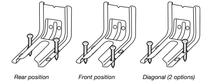
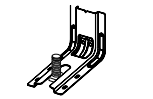
Wall Mounting
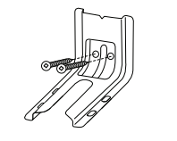
- Using two #12 x 1⁵⁄₈" Phillips-head screws provided, mount anti-tip bracket to the wall or floor.
- Move range close enough to opening to allow for final electrical connections. Remove shipping base, cardboard or hardboard from under range
- Move range into its final location, making sure rear leveling leg slides into anti-tip bracket.
- Move range forward onto shipping base, cardboard or hardboard to continue installing the range using the following installation instructions.
Electrical Connection
Power Supply Cord
WARNING
Electrical Shock Hazard
Disconnect power before servicing.
Use a new 40 amp power supply cord.
Plug into a grounded outlet.
Failure to follow these instructions can result in death, fire, or electrical shock.
Direct Wire
WARNING
Electrical Shock Hazard
Disconnect power before servicing.
Use 8 gauge copper or 6 gauge aluminum wire.
Electrically ground range.
Failure to follow these instructions can result in death, fire, or electrical shock.
- Disconnect power
- Remove the terminal block cover screws located on the back of the range. Pull cover down and toward you to remove cover from range.
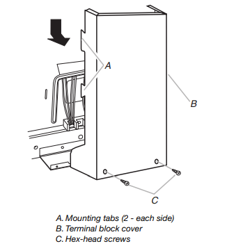
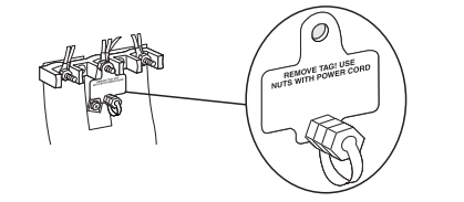
- Remove plastic tag holding three 10-32 hex nuts from the middle post of the terminal block.
- Add strain relief.
Style 1: Power Supply Cord Strain Relief
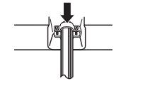
- Remove the knockout for the power supply cord.
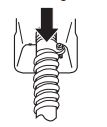
- Assemble a UL listed strain relief in the opening.
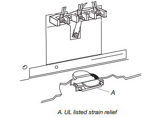
- Tighten strain relief screw against the power supply cord
Style 2: Direct Wire Strain Relief
- Remove the knockout as needed for the flexible conduit connection.
- Assemble a UL listed conduit connector in the opening.
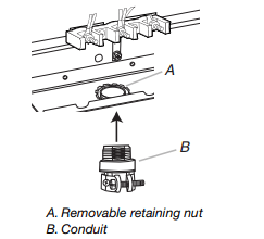
- Tighten strain relief screw against the flexible conduit.
5. Complete installation following instructions for your type of electrical connection:
4-wire (recommended)
3-wire (if 4-wire is not available)
Electrical Connection Options
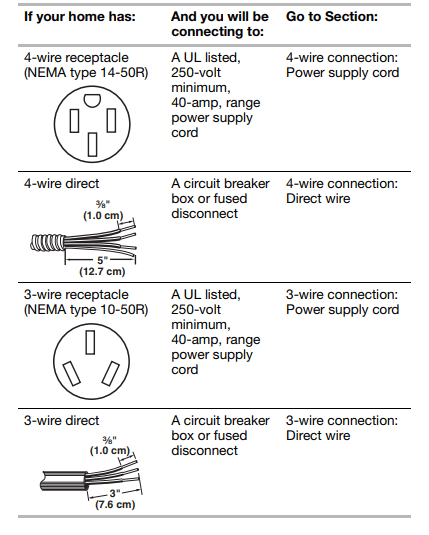
4-Wire Connection: Power Supply Cord
Use this method for:
- New branch-circuit installations (1996 NEC)
- Mobile homes
- Recreational vehicles
- In an area where local codes prohibit grounding through the neutral
- Cut out and remove part of metal ground strap, as shown.
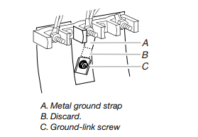
- Use a Phillips screwdriver to remove the ground-link screw from the back of the range. Save the ground-link screw and the end of the ground link under the screw.
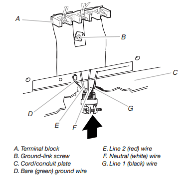
- Feed the power supply cord through the strain relief on the cord/conduit plate on bottom of range. Allow enough slack to easily attach the wiring to the terminal block.
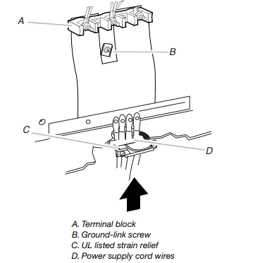
- Use a Phillips screwdriver to connect the green ground wire from the power supply cord to the range with the ground-link screw and ground-link section. The ground wire must be attached first.
- . Use ³⁄₈" nut driver to connect the neutral (white) wire to the center terminal block post with one of the 10–32 hex nuts.
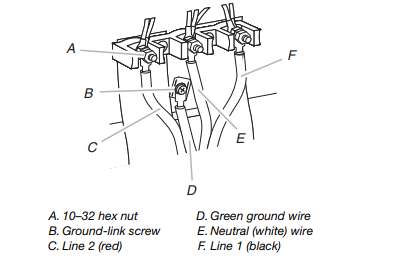
- Connect line 2 (red) and line 1 (black) wires to the outer terminal block posts with 10-32 hex nuts.
- Securely tighten hex nuts. NOTE: For power supply cord replacement, use only a power cord rated at 250 volts minimum, 40 amps or 50 amps that is marked for use with nominal 1³⁄₈" (3.5 cm) diameter connection opening, with ring terminals and marked for use with ranges.
- Tighten strain relief screws.
- Replace terminal block access cover
- Plug power cord into grounded outlet (see “Electrical Requirements” section).
- Slide range backs so that the rear range foot is engaged in the anti-tip bracket slot.
3-Wire Connection: Power Supply Cord
Use this method only if local codes permit connecting chassis ground conductor to neutral wire of power supply cord.
- Feed the power supply cord through the strain relief on the cord/conduit plate on bottom of range. Allow enough slack to easily attach the wiring to the terminal block.
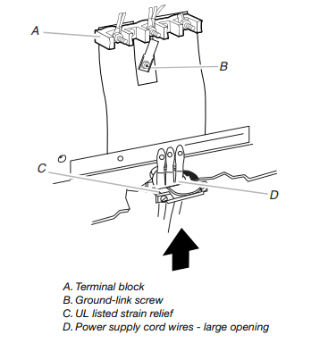
- Use ³⁄₈" nut driver to connect the neutral (white) wire to the center terminal block post with one of the 10–32 hex nuts.
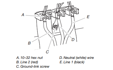
- Connect line 2 (red) and line 1 (black) wires to the outer terminal block posts with 10-32 hex nuts.
- Securely tighten hex nuts. NOTE: For power supply cord replacement, use only a power cord rated at 250 volts minimum, 40 amps or 50 amps that is marked for use with nominal 1³⁄₈" (3.5 cm) diameter connection opening, with ring terminals and marked for use with ranges.
- Tighten strain relief screws.
- Replace terminal block access cover.
- Plug power cord into grounded outlet (see “Electrical Requirements” section).
- Slide range backs so that the rear range foot is engaged in the anti-tip bracket slot
Direct Wire Installation: Copper or Aluminum Wire
This range may be connected directly to the fuse disconnect or circuit breaker box. Depending on your electrical supply, make the required 3-wire or 4-wire connection
- Strip outer covering back 3" (7.6 cm) to expose wires. Strip the insulation back ³⁄₈" (1.0 cm) from the end of each wire.
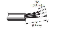
- Allow enough slack in the wire to easily attach the wiring terminal block.
- Complete electrical connection according to your type of electrical supply (4-wire or 3-wire connection).
4-Wire Connection: Direct Wire
Use this method for:
- New branch-circuit installations (1996 NEC)
- Mobile homes
- Recreational vehicles
- In an area where local codes prohibit grounding through the neutral
- Cut out and remove part of metal ground strap, as shown.
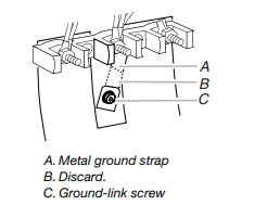
- Use a Phillips screwdriver to remove the ground-link screw from the back of the range. Save the ground-link screw and the end of the ground link under the screw.
- Pull the wires through the strain relief on bottom of range. Allow enough slack to easily attach wiring to the terminal block.
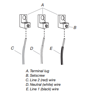
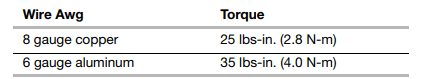
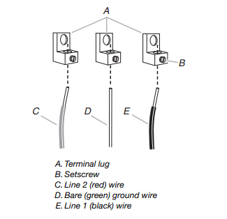
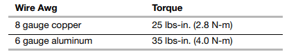
- Attach terminal lugs to line 1 (black), neutral (white), and line 2 (red) wires. Loosen (do not remove) the setscrew on the front of the terminal lug and insert exposed wire end through bottom of terminal lugs. Securely tighten setscrew to torque as shown in the following Bare Wire Torque Specifications chart.
Bare Wire Torque Specifications
Attaching terminal lugs to the terminal block - 20 lbs-in. (2.3 N-m)
- Use a hex driver or Phillips screwdriver to connect the bare (green) ground wire to the range with the ground-link screw and ground-link section. The ground wire must be attached first and must not contact any other terminal.
- Use ³⁄₈" nut driver to connect the neutral (white) wire to the center terminal block post with one of the 10–32 hex nuts.
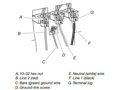
- Connect line 2 (red) and line 1 (black) wires to the outer terminal block posts with 10-32 hex nuts.
- Securely tighten hex nuts.
- Replace terminal block access cover.
- Slide range backs so that the rear range foot is engaged in the anti-tip bracket slot
3-Wire Connection: Direct Wire
Use this method only if local codes permit connecting ground conductor to neutral supply wire.
- Pull the wires through the conduit on cord/conduit plate on bottom of range. Allow enough slack to easily attach the wiring to the terminal block.
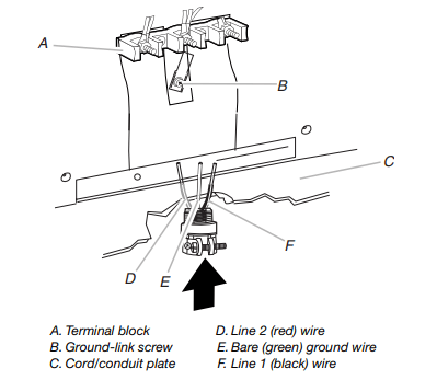
- Attach terminal lugs to line 2 (red), bare (green) ground, and line 1 (black) wires. Loosen (do not remove) the setscrew on the front of the terminal lug and insert exposed wire end through bottom of terminal lugs. Securely tighten setscrew to torque as shown in the following Bare Wire Torque Specifications chart.
Bare Wire Torque Specifications
Attaching terminal lugs to the terminal block - 20 lbs-in. (2.3 N-m)
- Use ³⁄₈" nut driver to connect the bare (green) ground wire to the center terminal block post with one of the 10–32 hex nuts.
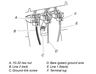
- Connect line 2 (red) and line 1 (black) wires to the outer terminal block posts with 10-32 hex nuts.
- Securely tighten hex nuts
- Replace terminal block access cover
- Slide range backs so that the rear range foot is engaged in the anti-tip bracket slot.
Verify Anti-Tip Bracket Is Installed and Engaged
On Ranges Equipped with a Storage Drawer:
- Remove the storage drawer. See “Storage Drawer” section.
- Use a flashlight to look underneath the bottom of the range.
- Visually check that the rear range foot is inserted into the slot of the anti-tip bracket.
On Ranges Equipped with a Warming Drawer or Premium Storage Drawer:
- Place the outside of your foot against the bottom front of the warming drawer or premium storage drawer, and grasp the lower right-hand or left-hand side of the control panel as shown.
NOTE: If your countertop is mounted with a backsplash, it may be necessary to grasp the range higher than is shown in the illustration.
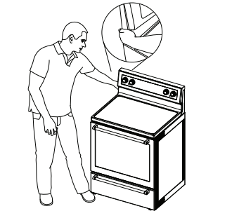
- Slowly attempt to tilt the range forward. If you encounter immediate resistance, the range foot is engaged in the anti-tip bracket.
- . If the rear of the range lifts more than ½" (1.3 cm) off the floor without resistance, stop tilting the range and lower it gently back to the floor. The range foot is not engaged in the anti-tip bracket.
IMPORTANT: If there is a snapping or popping sound when lifting the range, the range may not be fully engaged in the bracket. Check to see if there are obstructions keeping the range from sliding to the wall or keeping the range foot from sliding into the bracket. Verify that the bracket is held securely in place by the mounting screws.
- Slide the range forward, and verify that the anti-tip bracket is securely attached to the floor or wall.
- Slide range back so the rear range foot is inserted into the slot of the anti-tip bracket.
IMPORTANT: If the back of the range is more than 2" (5.1 cm) from the mounting wall, the rear range foot may not engage the bracket. Slide the range forward and determine if there is an obstruction between the range and the mounting wall. If you need assistance or service, refer to the “Assistance or Service” section of the Use and Care Guide, or the cover or “Warranty” section of the User Instructions, for contact information.
- Repeat steps 1 and 2 to ensure that the range foot is engaged in the anti-tip bracket. If the rear of the range lifts more than ½" (1.3 cm) off the floor without resistance, the anti-tip bracket may not be installed correctly. Do not operate the range without anti-tip bracket installed and engaged. Please reference the “Assistance or Service” section of the Use and Care Guide, or the cover or “Warranty” section of the User Instructions, to contact service.
Level Range
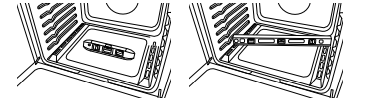
Determine if you have AquaLift®† Technology or Steam Clean by referring to the “Range Care” section of the User Instructions. For Ranges with AquaLift® Technology or Steam Clean:
- Place level on the oven bottom as indicated in one of the two figures below, depending on the size of the level. Check with the level: side to side and front to back
- If range is not level, pull range forward until rear leveling leg is removed from the anti-tip bracket.
- Follow the directions in Style 1 or Style 2, depending on the style of drawer supplied with the range.
For Ranges without AquaLift® Technology or Steam Clean:
- Place a standard flat rack in oven.
- Place level on the rack and check levelness of the range, first side to side; then front to back.
- If range is not level, pull range forward until rear leveling leg is removed from the anti-tip bracket.
- Follow the directions in Style 1 or Style 2, depending on the style of drawer supplied with the range.
Style 1: Ranges Equipped with a Storage Drawer:
Use a ¼" drive ratchet, wrench or pliers to adjust leveling legs up or down until the range is level. Push range back into position. Check that rear leveling leg is engaged in the anti-tip bracket.
Style 2: Ranges Equipped with a Warming Drawer or Premium Storage Drawer:
Use a wrench or pliers to adjust leveling legs up or down until the range is level. Push range back into position. Check that rear leveling leg is engaged in the anti-tip bracket.
NOTE: Range must be level for satisfactory baking performance and best cleaning results using AquaLift® Technology and Steam Clean functions.
Warming Drawer or Premium Storage Drawer (on some models)
Remove all items from inside the warming drawer or premium storage drawer, and allow the range to cool completely before attempting to remove the drawer.
To Remove:
- Open the warming drawer or premium storage drawer to its fully open position.
- Using a flat-blade screwdriver, gently loosen the warming drawer or premium storage drawer from the glide alignment notch and lift up the drawer alignment tab from the glide.
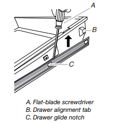
- Repeat Step 2 on the other side. The warming drawer or premium storage drawer is no longer attached to the drawer glides. Using both hands, pick up the warming drawer or premium storage drawer to complete the removal.
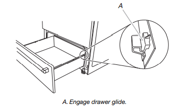
To Replace:
- Align the forward drawer notches with the notches in the drawer glides on both sides. Place the rear alignment tabs into the drawer glides on both sides.
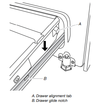
- Push the warming drawer or premium storage drawer in all the way.
- Gently open and close the warming drawer or premium storage drawer to ensure it is seated properly on the glides on both sides.
Storage Drawer (on some models)
The storage drawer can be removed. Before removing, make sure drawer is cool and empty.
To Remove:
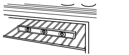
- Pull the storage drawer straight back to the drawer stop
- Lift up the front of the drawer and pull the drawer out
To Replace:
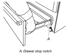
- Lift up the front of the drawer and place the rear of the drawer inside the range so that the drawer stop notch is behind the drawer glide.
- Lower the drawer so that the edge of the slide rail drops into the slot in the drawer glide.
- Slowly push the drawer into the range
NOTE: When properly installed, the rear slides on the bottom of the drawer will engage the base rails and the drawer will not tip when items are placed in the drawer.
Complete Installation
- Check that all parts are now installed. If there is an extra part, go back through the steps to see which step was skipped.
- Check that you have all of your tools.
- Dispose of/recycle all packaging materials.
- Check that the range is level. See the “Level Range” section.
- Use a mild solution of liquid household cleaner and warm water to remove waxy residue caused by shipping material. Dry thoroughly with a soft cloth. For more information, read the “Range Care” section of the Use and Care Guide or User Instructions.
- Read the “Range Use” section in the range Use and Care Guide or User Instructions.
- Plug power cord into appropriate outlet. Turn on power.
- Turn on surface burners and oven. See the Use and Care Guide or User Instructions for specific instruction on range operation.
If range does not operate, check the following:
- Household fuse is intact and tight; or circuit breaker has not tripped.
- Range is plugged into a grounded outlet.
- Electrical supply is connected.
IMPORTANT: If the range control displays an “F9” or “F9, E0” error code, the electrical outlet in the home may be miswired. Contact a qualified electrician to verify the electrical supply.
- See the “Troubleshooting” section in the Use and Care Guide or User Instructions. When the range has been on for 5 minutes, check for heat. If range is cold, turn off the range and contact a qualified technician.
Moving the Range
WARNING
Tip Over Hazard
A child or adult can tip the range and be killed.
Install anti-tip bracket to floor or wall per installation instructions.
Slide range back so rear range foot is engaged in the slot of the anti-tip bracket.
Re-engage anti-tip bracket if range is moved.
Do not operate range without anti-tip bracket installed and engaged.
Failure to follow these instructions can result in death or serious burns to children and adults.
When moving range, slide range onto cardboard or hardboard to avoid damaging the floor covering. If removing the range is necessary for cleaning or maintenance:
For Power Supply Cord-Connected Ranges:
- Slide range forward.
- Unplug the power supply cord.
- Complete cleaning or maintenance.
- Plug in power supply cord.
- Check that the anti-tip bracket is installed and engaged. See the “Verify Anti-Tip Bracket Is Installed and Engaged” section.
- Check that range is level.
For Direct-Wired Ranges:
WARNING
Electrical Shock Hazard
Disconnect power before servicing.
Replace all parts and panels before operating.
Failure to do so can result in death or electrical shock.
- Disconnect power.
- Slide range forward.
- Complete cleaning or maintenance.
- Check that the anti-tip bracket is installed and engaged. See the “Verify Anti-Tip Bracket Is Installed and Engaged” section.
- Check that range is level
- Reconnect power