Owner 's Manual Electric Range
RANGE MAINTENANCE AND CARE
Clean Cycle

AquaLift® Technology is an innovative cleaning solution that utilizes heat and water to release baked-on spills from the oven in less than 1 hour. This new cleaning technology is a low-heat, odor-free alternative to traditional self-cleaning options. Allow the oven to cool to room temperature before using the Clean cycle. If your oven cavity is above 200°F (93°C), it will appear in the display, and the Clean cycle will not be activated until the oven cavity cools down.
To Clean:
1. Remove all racks and accessories from the oven cavity, and wipe excess soil. Use a plastic scraper to remove easily removed soils
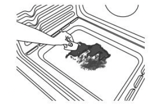
2. Pour distilled or filtered water onto the bottom of the empty oven, and close the oven door.
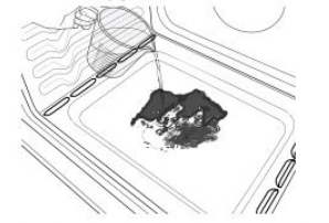
IMPORTANT: Do not use chemicals or other additives with the water. Do not open the oven door during the Clean cycle. The water on the oven bottom is hot.
3. Press CLEAN or AQUALIFT SELF CLEAN and then START on the oven control panel.
4. Allow 40 minutes for cleaning and cool down. A beep will sound when the Clean cycle is complete.
5. Press CANCEL, CANCEL UPPER or OFF at the end of the cycle. Cancel, Cancel Upper or Off may be pressed at any time to stop the Clean cycle.
6. Remove the residual water and loosened soils with a sponge or cloth immediately after the Clean cycle is complete. Much of the initial 2 cups (16 oz [500 mL]) of water will remain in the oven after the cycle is completed. If additional soils remain, leave a small amount of water in the oven bottom to assist with the cleaning.
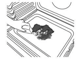
7. If any soils remain, remove them with a non-scratch scrubbing sponge or plastic scraper. Additional Clean cycles may be run to help remove the stubborn soils.
IMPORTANT: Do not use oven cleaners. The use of chemicals, including commercial oven cleaners or metal scouring pads, may cause permanent damage to the porcelain surface of the oven interior.
NOTES:
- The range should be level to ensure that the entire surface of the bottom of the oven cavity is covered by water at the beginning of the Clean cycle.
- For best results, use distilled or filtered water. Tap water may leave mineral deposits on the oven bottom.
- Before removing the residual water and loosened soils at the end of the Clean cycle, insert a cloth or paper towel between the lower edge of the oven door and the front frame to keep water from spilling onto the front of the range and the floor.
- Soil baked on through several cooking cycles will be more difficult to remove with the Clean cycle.
- Nonabrasive scrub sponges or eraser style cleaning pads (without cleaners) can be effective for cleaning the oven cavity walls, oven door and oven bottom for difficult soils. For best results, moisten the pads and sponges before use.
- Run an additional Clean cycle for stubborn soils.
- Affresh® Kitchen Appliance Cleaner and affresh® Cooktop Cleaner may be used to clean the oven bottom, walls, and door when the oven has finished the cycle and returned to room temperature. If affresh® Cooktop Cleaner is used, it is recommended to wipe out the cavity with distilled water as well. Refer to the Quick Start Guide for ordering information.
- Additional AquaLift® Technology Cleaning Kits may be obtained by ordering Part Number W10423113RP. Refer to the Quick Start Guide for ordering information.
- For assistance with AquaLift® Technology, call 1-877-258- 0808 in the U.S.A. or 1-800-807-6777 in Canada.
General Cleaning
IMPORTANT: Before cleaning, make sure all controls are off and the oven and cooktop are cool. Always follow label instructions on cleaning products. Soap, water, and a soft cloth or sponge are suggested first, unless otherwise noted.
EXTERIOR PORCELAIN ENAMEL SURFACES (on some models)
Food spills containing acids, such as vinegar and tomato, should be cleaned as soon as the entire range is cool. These spills may affect the finish.
Cleaning Method:
- Glass cleaner, mild liquid cleaner, or nonabrasive scrubbing pad: Gently clean around the model/serial/rating plate because scrubbing may remove numbers.
- Affresh® Kitchen and Appliance Cleaner Part Number W10355010 (not included): See the Quick Start Guide for contact information.
STAINLESS STEEL (on some models)
NOTE: To avoid damage to stainless steel surfaces, do not use soap-filled scouring pads, abrasive cleaners, Cooktop Cleaner, steel-wool pads, gritty washcloths, or abrasive paper towels. Damage may occur to stainless steel surfaces, even with one-time or limited use
Cleaning Method:
Rub in direction of grain to avoid damaging.
- Affresh® Stainless Steel Cleaner Part Number W10355016 (not included): See the Quick Start Guide for contact information.
METALLIC PAINT (on some models)
Do not use abrasive cleaners, cleaners with bleach, rust removers, ammonia, or sodium hydroxide (lye) because paint surface may stain.
CERAMIC GLASS COOKTOP CLEANING
Cleaning Method:
To avoid damaging the cooktop, do not use steel wool, abrasive powder cleansers, chlorine bleach, rust remover, or ammonia.
1. Remove food/residue with the Cooktop Scraper.

- For best results, use the Cooktop Scraper while the cooktop is still warm but not hot to the touch. It is recommended to wear an oven mitt while scraping the warm cooktop.
- Hold the Cooktop Scraper at approximately a 45° angle against the glass surface and scrape the residue. It will be necessary to apply pressure in order to remove the residue.
Allow the cooktop to cool down completely before proceeding to Step 2.
2. Apply a few dime-sized drops of Cooktop Cleaner to the affected areas.
- Rub affresh® Cleaner onto the cooktop surface with the blue Cooktop Cleaning Pad. Some pressure is needed to remove stubborn stains.
- Allow the cleaner to dry to a white haze before proceeding to Step 3.
3. Polish with a clean, dry cloth or a clean, dry paper towel.

- Repeat steps 1 through 3 as necessary for stubborn or burned-on stains.
The Complete Cooktop Cleaner Kit is available for order including the following:
- Cooktop Scraper
- Affresh® Cooktop Cleaner
- Blue Cooktop Cleaning Pads
See the Quick Start Guide for ordering information.
COOKTOP CONTROLS
To avoid damage to the cooktop controls, do not use steel wool, abrasive cleansers, or oven cleaner. To avoid damage, do not soak knobs. When replacing knobs, make sure knobs are in the Off position. On some models, do not remove seals under knobs.
Cleaning Method:
- Soap and water: Pull knobs straight away from control panel to remove
CONTROL PANEL AND OVEN DOOR EXTERIOR
To avoid damage to the control panel, do not use abrasive cleaners, steel-wool pads, gritty washcloths, or abrasive paper towels.
Cleaning Method:
- Glass cleaner and soft cloth or sponge: Apply glass cleaner to soft cloth or sponge, not directly on panel.
- Affresh® Kitchen and Appliance Cleaner Part Number W10355010 (not included): See the Quick Start Guide for contact information.
OVEN RACKS
Cleaning Method:
- Steel-wool pad
- For racks that have discolored and are harder to slide, a light coating of vegetable oil applied to the rack guides will help them slide
- Dishwasher (steam rack water reservoir only, not racks): Although the water reservoir is durable, it may lose its shine and/or discolor when washed in a dishwasher
STORAGE DRAWER OR WARMING DRAWER (on some models)
Check that storage drawer or warming drawer is cool and empty before cleaning.
Cleaning Method:
OVEN CAVITY
Use AquaLift® Technology regularly to clean oven spills. Do not use oven cleaners Food spills should be cleaned when oven cools. At high temperatures, foods react with porcelain. Staining, etching, pitting, or faint white spots can result.
Cleaning Method:
- Clean cycle: See “Clean Cycle” first.
INSTALLATION INSTRUCTIONS REQUIREMENTS
Tools and Parts
Gather the required tools and parts before starting installation. Read and follow the instructions provided with any tools listed here.
Tools needed
- Tape measure
- Flat-blade screwdriver
- Phillips screwdriver
- Level
- Hammer
- Hand or electric drill
- Wrench or pliers
- Marker or pencil
- Masking tape
- 1/4" (6.4 mm) drive ratchet
- 1/4" (6.4 mm) nut driver
- 3/8" (9.5 mm) and 5/16" ( 8 mm) nut driver
- 1/8" (3.2 mm) drill bit (for wood floors)
- Tin snips or large wire cutters (for cutting ground strap if necessary)
Parts supplied
Check that all parts are included.
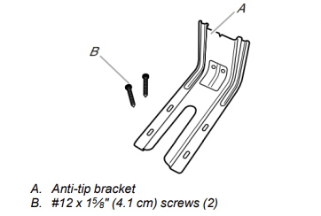
- Anti-tip bracket must be securely mounted to floor or wall. Thickness of flooring may require longer screws to anchor bracket to floor.
Parts needed
Check local codes. Check existing electrical supply. See “Electrical Requirements” section. It is recommended that all electrical connections be made by a licensed, qualified electrical installer.
Location Requirements
IMPORTANT: Observe all governing codes and ordinances.
- It is the installer’s responsibility to comply with installation clearances specified on the model/serial rating plate. The model/serial rating plate is located on the frame behind a top corner of the door or either side of the drawer.
- To eliminate the risk of burns or fire by reaching over heated surface units, cabinet storage space located above the surface units should be avoided. If cabinet storage is to be provided, the risk can be reduced by installing a range hood that projects horizontally a minimum of 5" (12.7 cm) beyond the bottom of the cabinets.
- Cabinet opening dimensions that are shown must be used. Given dimensions are minimum clearances.
- The anti-tip bracket must be installed. To install the anti-tip bracket shipped with the range, see “Install Anti-Tip Bracket” section.
- Grounded electrical supply is required. See “Electrical Requirements” section.
IMPORTANT: To avoid damage to your cabinets, check with your builder or cabinet supplier to make sure that the materials used will not discolor, delaminate or sustain other damage. This oven has been designed in accordance with the requirements of UL and CSA International and complies with the maximum allowable wood cabinet temperatures of 194°F (90°C)
Mobile Home - Additional Installation Requirements
The installation of this range must conform to the Manufactured Home Construction and Safety Standard, Title 24 CFR, Part 3280 (formerly the Federal Standard for Mobile Home Construction and Safety, Title 24, HUD Part 280). When such standard is not applicable, use the Standard for Manufactured Home Installations, ANSI A225.1/NFPA 501A or with local codes. In Canada, the installation of this range must conform with the current standards CAN/CSA-Z240-latest edition, or with local codes.
Mobile Home Installations Require:
- When this range is installed in a mobile home, it must be secured according to the instructions in this document.
Cabinet Dimensions
Cabinet opening dimensions shown are for 25" (64.0 cm) countertop depth, 24" (61.0 cm) base cabinet depth and 36" (91.4 cm) countertop height.
IMPORTANT: If installing a range hood or microwave hood combination above the range, follow the range hood or microwave hood combination installation instructions for dimensional clearances above the cooktop surface. A freestanding range may be installed next to combustible walls with zero clearance.
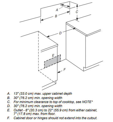
*NOTE: 24" (61.0 cm) minimum when bottom of wood or metal cabinet is covered by not less than 1/4" (0.64 cm) flame retardant millboard covered with not less than No. 28 MSG sheet steel, 0.015" (0.4 mm) stainless steel, 0.024" (0.6 mm) aluminum or 0.020" (0.5 mm) copper. 30" (76.2 cm) minimum clearance between the top of the cooking platform and the bottom of an uncovered wood or metal cabinet.
Electrical Requirements - U.S.A. Only
If codes permit and a separate ground wire is used, it is recommended that a qualified electrical installer determine that the ground path and wire gauge are in accordance with local codes.
Do not use an extension cord. Be sure that the electrical connection and wire size are adequate and in conformance with the National Electrical Code, ANSI/NFPA 70-latest edition and all local codes and ordinances.
WARNING: Improper connection of the equipment-grounding conductor can result in a risk of electric shock. Check with a qualified electrician or service technician if you are in doubt as to whether the appliance is properly grounded. Do not modify the power supply cord plug. If it will not fit the outlet, have a proper outlet installed by a qualified electrician.
Electrical Connection
To properly install your range, you must determine the type of electrical connection you will be using and follow the instructions provided for it here.
- Range must be connected to the proper electrical voltage and frequency as specified on the model/serial/rating plate. The model/serial/rating plate is located behind the oven door on the top right-hand side of the oven frame.
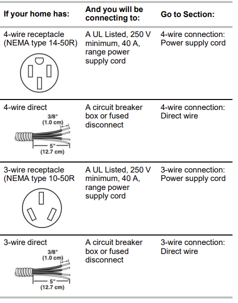
- This range is manufactured with the neutral terminal connected to the cabinet. Use a 3-wire, UL listed, 40 or 50 A power supply cord (pigtail). See the following Range Rating chart. If local codes do not permit ground through the neutral, use a 4-wire power supply cord rated at 250 V, 40 or 50 A and investigated for use with ranges.
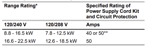
* The NEC calculated load is less than the total connected load listed on the model/serial/rating plate.
** If connecting to a 50 A circuit, use a 50 A rated cord with kit. For 50 A rated cord kits, use kits that specify use with a nominal 13/8" (34.9 mm) diameter connection opening.
- A circuit breaker is recommended.
- The range can be connected directly to the circuit breaker box or fused disconnect) through flexible or nonmetallic sheathed, copper or aluminum cable. See the "Electrical Connection - U.S.A. Only" section.
- Allow 2 to 3 ft (61.0 cm to 91.4 cm) of slack in the line so that the range can be moved if servicing is ever necessary.
- A UL listed conduit connector must be provided at each end of the power supply cable (at the range and at the junction box).
- Wire sizes and connections must conform with the rating of the range.
- The Tech Sheet is located on the back of the range inside a clear plastic bag.
If connecting to a 4-wire system:
This range is manufactured with the ground connected to the neutral by a link. The ground must be revised so the green ground wire of the 4-wire power supply cord is connected to the cabinet. See the “Electrical Connection - U.S.A. Only” section.
Grounding through the neutral conductor is prohibited for new branch-circuit installations (1996 NEC); mobile homes; and recreational vehicles, or an area where local codes prohibit grounding through the neutral conductor.
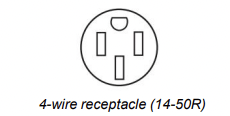
When a 4-wire receptacle of NEMA Type 14-50R is used, a matching UL listed, 4-wire, 250 V, 40 or 50 A, range power supply cord (pigtail) must be used. This cord contains 4 copper conductors with ring terminals or open-end spade terminals with upturned ends, terminating in a NEMA Type 14- 50P plug on the supply end.
The fourth (grounding) conductor must be identified by a green or green/yellow cover and the neutral conductor by a white cover. Cord should be Type SRD or SRDT with a UL listed strain relief and be at least 4 ft (1.22 m) long.
The minimum conductor sized for the copper 4-wire power cord are:
- 40 A circuit
- 2 No.-8 conductors
- 1 No.-10 white neutral
- 1 No.-8 green grounding
If connecting to a 3-wire system:
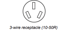
Local codes may permit the use of a UL listed, 3-wire, 250 V, 40 or 50 A range power supply cord (pigtail). This cord contains 3 copper conductors with ring terminals or open-end spade terminals with upturned ends, terminating in a NEMA Type 10-50P plug on the supply end. Connectors on the appliance end must be provided at the point the power supply cord enters the appliance. This uses a 3-wire receptacle of NEMA Type 10-50R.
INSTALLATION
Unpack Range
 Excessive Weight Hazard Use two or more people to move and install or uninstall appliance. Failure to do so can result in back or other injury.
1. Remove shipping materials, tape and film from range.
2. Remove oven racks and parts package from inside oven.
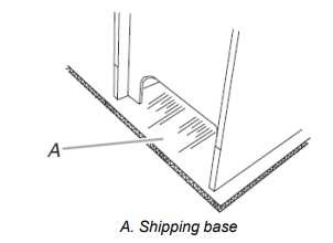
3. Do not remove the shipping base at this time.
4. On Ranges Equipped with a Storage Drawer:
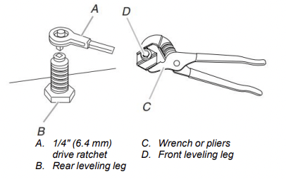
Remove the storage drawer. See the “Storage Drawer” section. Use a 1/4" (6.4 mm) drive ratchet to lower the rear leveling legs one-half turn. Use a wrench or pliers to lower front leveling legs one half turn.
On Ranges Equipped with a Warming Drawer or Premium Storage Drawer:
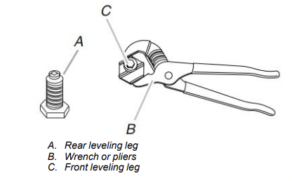
On ranges equipped with a warming drawer or premium storage drawer, the rear legs cannot be accessed by removing the warming drawer or premium storage drawer. It will be necessary to adjust the rear legs from outside the range. Use wrench or pliers to lower the front and rear leveling legs one half turn.
Electrical Connection - U.S.A. Only
Power Supply Cord
Electrical Shock Hazard Disconnect power before servicing. Use a new 40 amp power supply cord. Plug into a grounded outlet. Failure to follow these instructions can result in death, fire, or electrical shock.
Direct Wire
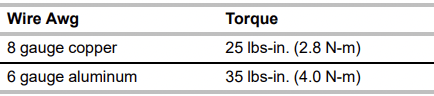
Electrical Shock Hazard Disconnect power before servicing. Use 8 gauge copper or 6 gauge aluminum wire. Electrically ground range. Failure to follow these instructions can result in death, fire, or electrical shock.
1. Disconnect power.
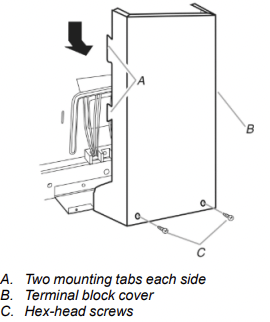
2. Remove the terminal block cover screws located on the back of the range. Pull cover down and toward you to remove cover from range.
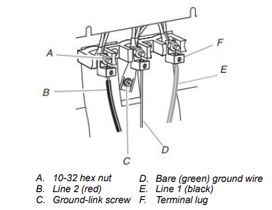
3. Depending on your model, remove plastic tag holding three 10-32 hex nuts from the middle post of the terminal block.
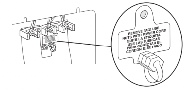
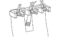
OR Remove the top 10-32 hex nut from each of the 3 terminal blocks and set aside.
4. Add strain relief.
Style 1: Power supply cord strain relief
- Remove the knockout for the power supply cord.
- Assemble a UL listed strain relief in the opening.
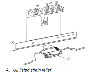
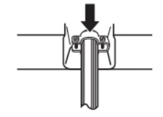
- Tighten strain relief screw against the power supply cord.
Style 2: Direct wire strain relief
- Remove the knockout as needed for the flexible conduit connection.
- Assemble a UL listed conduit connector in the opening.
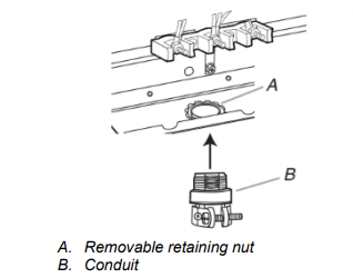
- Tighten strain relief screw against the flexible conduit.
5. Complete installation following instructions for your type of electrical connection:
- 4-wire (recommended)
- 3-wire (if 4-wire is not available)
Electrical Connection Options
4-Wire Connection: Power Supply Cord
Use this method for:
- New branch-circuit installations (1996 NEC)
- Mobile homes
- Recreational vehicles
- In an area where local codes prohibit grounding through the neutral
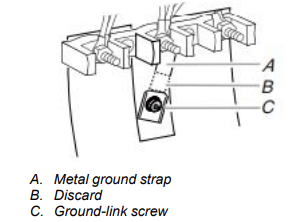
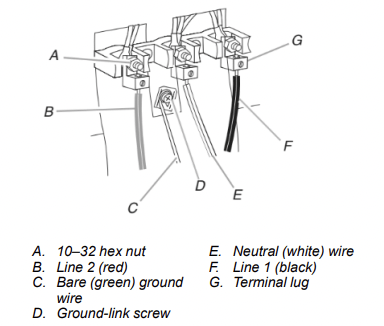
1. Part of metal ground strap must be cut out and removed.
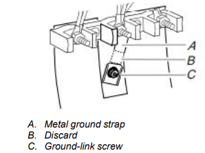
2. Use a Phillips screwdriver to remove the ground-link screw from the back of the range. Save the ground-link screw and the end of the ground link under the screw
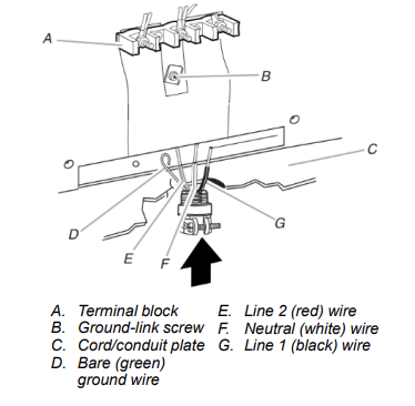
3. Feed the power supply cord through the strain relief on the cord/conduit plate on bottom of range. Allow enough slack to easily attach the wiring to the terminal block.
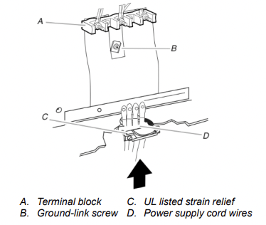
4. Use Phillips screwdriver to connect the green ground wire from the power supply cord to the range with the ground-link screw. The ground wire must be attached first.
5. Use 3/8" (9.5 mm) nut driver to connect the neutral (white) wire to the center terminal block post with one of the 10-32 hex nuts.
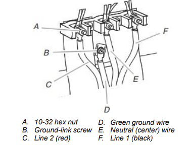
6. Connect line 2 (red) and line 1 (black) wires to the outer terminal block posts with 10-32 hex nuts.
7. Securely tighten hex nuts.
NOTE: For power supply cord replacement, use only a power cord rated at 250 V minimum, 40 A or 50 A that is marked for use with nominal 13⁄8" (3.5 cm) diameter connection opening, with ring terminals and marked for use with ranges.
8. Tighten strain relief screws.
9. Replace terminal block access cover.
3-Wire Connection: Power Supply Cord
Use this method only if local codes permit connecting chassis ground conductor to neutral wire of power supply cord.
1. Feed the power supply cord through the strain relief in the cord/conduit plate on bottom of range. Allow enough slack to easily attach the wiring to the terminal block.
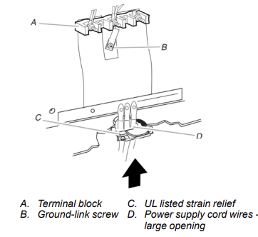
2. Use 3/8" (9.5 mm) nut driver to connect the neutral (white) wire to the center terminal block post with one of the 10-32 hex nuts.
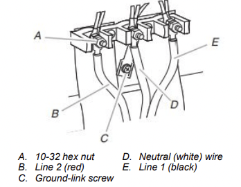
3. Connect line 2 (red) and line 1 (black) wires to the outer terminal block posts with 10-32 hex nuts.
4. Securely tighten hex nuts.
NOTE: For power supply cord replacement, only use a power cord rated at 250 V minimum, 40 A or 50 A that is marked for use with nominal 13/8" (3.5 cm) diameter connection opening, with ring terminals and marked for use with ranges.
5. Tighten strain relief screws.
IMPORTANT: Verify the tightness of the hex nuts.
6. Replace terminal block access cover.
Direct Wire Installation: Copper or Aluminum Wire
This range may be connected directly to the fuse disconnect or circuit breaker box. Depending on your electrical supply, make the required 3-wire or 4-wire connection.
1. Strip outer covering back 3" (7.6 cm) to expose wires. Strip the insulation back 1" (2.5 cm) from the end of each wire.
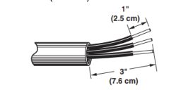
2. Allow enough slack in the wire to easily attach the wiring terminal block.
3. Complete electrical connection according to your type of electrical supply.
- 4-wire (recommended)
- 3-wire (if 4-wire is not available)
4-Wire Connection:
Direct Wire Use this method for:
- New branch-circuit installations (1996 NEC)
- Mobile homes
- Recreational vehicles
- In an area where local codes prohibit grounding through the neutral
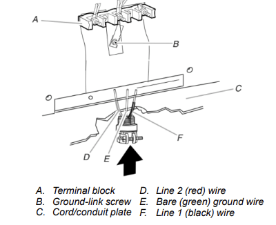
1. Part of metal ground strap must be cut out and removed.
2. Use a Phillips screwdriver to remove the ground-link screw from the back of the range. Save the ground-link screw and the end of the ground link under the screw.
3. Pull the wires through the strain relief on bottom of range. Allow enough slack to easily attach wiring to the terminal block.
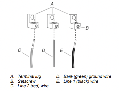
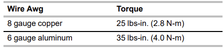
4. Attach terminal lugs to line 1 (black), neutral (white), and line 2 (red) wires. Loosen (do not remove) the setscrew on the front of the terminal lug and insert exposed wire end through bottom of terminal lugs. Securely tighten setscrew to torque as shown in the following Bare Wire Torque Specifications chart.
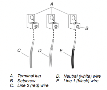
Bare Wire Torque Specifications
Attaching terminal lugs to the terminal block - 20 lbs-in. (2.3 N-m)
5. Use a hex or Phillips screwdriver to connect the bare (green) ground wire to the range with the ground-link screw and ground-link section. The ground wire must be attached first and must not contact any other terminal.
6. Use 3/8" nut driver to connect the neutral (white) wire to the center terminal block post with one of the 10–32 hex nuts.
7. Connect line 2 (red) and line 1 (black) wires to the outer terminal block posts with 10-32 hex nuts.
8. Securely tighten hex nuts.
9. Replace terminal block access cover.
3-Wire Connection:
Direct Wire Use this method only if local codes permit connecting ground conductor to neutral supply wire.
1. Pull the wires through the conduit on cord/conduit plate on bottom of range. Allow enough slack to easily attach the wiring to the terminal block.
2. Attach terminal lugs to line 2 (red), bare (green) ground, and line 1 (black) wires. Loosen (do not remove) the setscrew on the front of the terminal lug and insert exposed wire end through bottom of terminal lugs. Securely tighten setscrew to torque as shown in the following Bare Wire Torque Specifications chart.
Bare Wire Torque Specifications
Attaching terminal lugs to the terminal block - 20 lbs-in. (2.3 N-m)
3. Use 3/8" nut driver to connect the bare (green) ground wire to the center terminal block post with one of the 10–32 hex nuts.
4. Connect line 2 (red) and line 1 (black) wires to the outer terminal block posts with 10-32 hex nuts.
5. Securely tighten hex nuts.
6. Replace terminal block access cover.
Install Anti-Tip Bracket
 Tip Over Hazard
A child or adult can tip the range and be killed. Install anti-tip bracket to floor or wall per installation instructions. Slide range back so rear range foot is engaged in the slot of the anti-tip bracket. Re-engage anti-tip bracket if range is moved. Do not operate range without anti-tip bracket installed and engaged. Failure to follow these instructions can result in death or serious burns to children and adults
1. Remove the anti-tip bracket from where it is taped inside the storage drawer or warming drawer.
2. Determine which mounting method to use: floor or wall. If you have a stone or masonry floor, you can use the wall mounting method. If you are installing the range in a mobile home, you must secure the range to the floor.
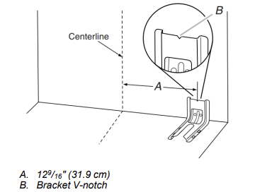
3. Determine and mark centerline of the cutout space. The mounting can be installed on either the left-side or right-side of the cutout. Position mounting bracket against the wall in the cutout so that the V-notch of the bracket is 12 9/16" (31.9 cm) from centerline as shown.
4. Drill two 1/8" (3 mm) holes that correspond to the bracket holes of the determined mounting method. See the following illustrations.
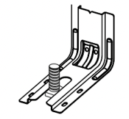
Floor Mounting
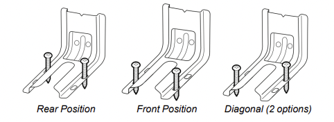
Wall Mounting
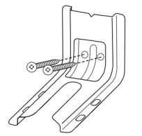
5. Using the Phillips screwdriver, mount anti-tip bracket to the wall or floor with the two #12 x 15/8" (41.3 mm) screws provided.
6. Move range close enough to opening to allow for final electrical connections. Remove shipping base, cardboard or hardboard from under range.
7. Move range into its final location, making sure rear leveling leg slides into anti-tip bracke
8. Move range forward onto shipping base, cardboard or hardboard to continue installing the range using the following installation instructions.
9. Plug power cord into a grounded outlet (see “Electrical Requirements” section).
10. Slide range back so that rear range foot is engaged in the antitip bracket slot.
Verify Anti-Tip Bracket Is Installed and Engaged
On Ranges Equipped with a Storage Drawer:
1. Remove the storage drawer. See “Storage Drawer” section.
2. Use a flashlight to look underneath the bottom of the range.
3. Visually check that the rear range foot is inserted into the slot of the anti-tip bracket.
On Ranges Equipped with a Warming Drawer or Premium Storage Drawer:
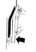
1. Place the outside of your foot against the bottom front of the warming drawer or premium storage drawer, and grasp the lower right or left side of the control panel as shown.
NOTE: If your countertop is mounted with a backsplash, it may be necessary to grasp the range higher than is shown in the illustration.
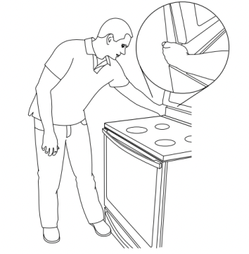
2. Slowly attempt to tilt the range forward. If you encounter immediate resistance, the range foot is engaged in the anti-tip bracket.
3. If the rear of the range lifts more than 1/2" (1.3 cm) off the floor without resistance, stop tilting the range and lower it gently back to the floor. The range foot is not engaged in the anti-tip bracket.
IMPORTANT: If there is a snapping or popping sound when lifting the range, the range may not be fully engaged in the bracket. Check to see if there are obstructions keeping the range from sliding to the wall or keeping the range foot from sliding into the bracket. Verify that the bracket is held securely in place by the mounting screws.
4. Slide the range forward, and verify that the anti-tip bracket is securely attached to the floor or wall.
5. Slide range back so the rear range foot is inserted into the slot of the anti-tip bracket.
IMPORTANT: If the back of the range is more than 2" (5.1 cm) from the mounting wall, the rear range foot may not engage the bracket. Slide the range forward and determine if there is an obstruction between the range and the mounting wall. If you need assistance or service, refer to the Quick Start Guide for contact information.
6. Repeat steps 1 and 2 to ensure that the range foot is engaged in the anti-tip bracket. If the rear of the range lifts more than 1/2" (1.3 cm) off the floor without resistance, the anti-tip bracket may not be installed correctly. Do not operate the range without anti-tip bracket installed and engaged. Please refer to the Quick Start Guide for contact information
Level Range
Determine if you have AquaLift® Technology or Steam Clean by referring to the “Range Maintenance and Care” section.
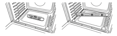
For Ranges with AquaLift® Technology or Steam Clean:
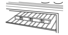
1. Place level on the oven bottom as indicated in one of the two figures below depending on the size of the level. Check with the level: side to side and front to back.
2. If range is not level, pull range forward until rear leveling leg is removed from the anti-tip bracket.
3. Follow the directions in Style 1 or Style 2, depending on the style of drawer supplied with the range.
For Ranges without AquaLift® Technology or Steam Clean:
1. Place a standard flat rack in oven.
2. Place level on the rack and check levelness of the range, first side to side; then front to back.
3. If range is not level, pull range forward until rear leveling leg is removed from the anti-tip bracket.
4. Follow the directions in Style 1 or Style 2, depending on the style of drawer supplied with the range.
Style 1: Ranges Equipped with a Storage Drawer:
Use a 1/4" drive ratchet, wrench or pliers to adjust leveling legs up or down until the range is level. Push range back into position. Check that rear leveling leg is engaged in the anti-tip bracket.
Style 2: Ranges Equipped with a Warming Drawer or Premium Storage Drawer:
Use a wrench or pliers to adjust leveling legs up or down until the range is level. Push range back into position. Check that rear leveling leg is engaged in the anti-tip bracket. NOTE: Range must be level for satisfactory baking performance and best cleaning results using AquaLift® Technology and Steam Clean functions.
Warming Drawer or Premium Storage Drawer (on some models)
Remove all items from inside the warming drawer or premium storage drawer, and allow the range to cool completely before attempting to remove the drawer.
To Remove:
1. Open the warming drawer or premium storage drawer to its fully open position.
2. Using a flat-blade screwdriver, gently loosen the warming drawer or premium storage drawer from the glide alignment notch and lift up the drawer alignment tab from the glide.
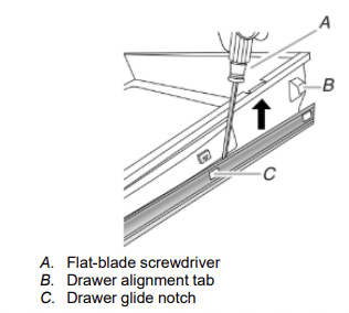
3. Repeat Step 2 on the other side. The warming drawer or premium storage drawer is no longer attached to the drawer glides. Using both hands, pick up the warming drawer or premium storage drawer to complete the removal.
To Replace:
1. Align the forward drawer notches with the notches in the drawer glides on both sides. Place the rear alignment tabs into the drawer glides on both sides.
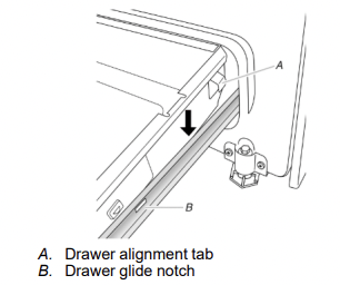
2. Push the warming drawer or premium storage drawer in all the way.
3. Gently open and close the warming drawer or premium storage drawer to ensure it is seated properly on the glides on both sides.
Storage Drawer (on some models)
The storage drawer can be removed. Before removing, make sure drawer is cool and empty.
To Remove:
1. Pull the storage drawer straight back to the drawer stop.
2. Lift up the front of the drawer and pull the drawer out.
To Replace:
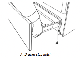
1. Lift up the front of the drawer and place the rear of the drawer inside the range so that the drawer stop notch is behind the drawer glide.
2. Lower the drawer so that the edge of the slide rail drops into the slot in the drawer glide.
3. Slowly push the drawer into the range.
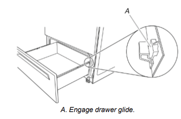
NOTE: When properly installed, the rear slides on the bottom of the drawer will engage the base rails and the drawer will not tip when items are placed in the drawer.
If removing the range is necessary for cleaning or maintenance:
1. Slide range forward.
2. Unplug the power supply cord.
3. Complete cleaning or maintenance.
4. Plug in power supply cord.
5. Check that the anti-tip bracket is installed and engaged. See the “Verify Anti-Tip Bracket Is Installed and Engaged” section.
6. Check that range is level.
Oven Door
For normal range use, it is not suggested to remove the oven door. However, if removal is necessary, make sure the oven is off and cool. Then, follow these instructions. The oven door is heavy.
To Remove:
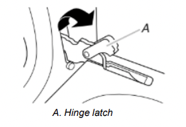
1. Open oven door all the way.
2. Pinch the hinge latch between two fingers and pull forward. Repeat on other side of oven door.
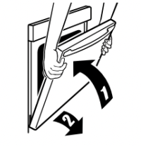
3. Close the oven door as far as it will shut.
4. Lift the oven door while holding both sides. Continue to push the oven door closed and pull it away from the oven door frame.
To Replace:
1. Insert both hanger arms into the door.
2. Open the oven door. You should hear a “click” as the door is set into place.
3. Move the hinge levers back to the locked position. Check that the door is free to open and close. If it is not, repeat the removal and installation procedures.
Complete Installation
1. Check that all parts are now installed. If there is an extra part, go back through the steps to see which step was skipped.
2. Check that you have all of your tools.
3. Dispose of/recycle all packaging materials.
4. Check that the range is level. See the “Level Range” section.
5. Use a mild solution of liquid household cleaner and warm water to remove waxy residue caused by shipping material. Dry thoroughly with a soft cloth. For more information, read the “Range Maintenance and Care” section.
6. Read the Quick Start Guide and online Control Guide.
7. Turn on surface burners and oven. See the Quick Start Guide and online Control Guide for specific instruction on range operation. If range does not operate, check the following:
- Household fuse is intact and tight; or circuit breaker has not tripped.
- Range is plugged into a grounded outlet (see the “Electrical Requirements” section).
- Electrical supply is connected.
IMPORTANT: If the range control displays an F9 or F9, E0 error code, the electrical outlet may be miswired. Contact a qualified electrician to verify the electrical supply.
- See the online troubleshooting section. When the range has been on for 5 minutes, check for heat. If range is cold, turn off the range and contact a qualified technician.
Moving the Range
Tip Over Hazard
A child or adult can tip the range and be killed. Install anti-tip bracket to floor or wall per installation instructions. Slide range back so rear range foot is engaged in the slot of the anti-tip bracket. Re-engage anti-tip bracket if range is moved. Do not operate range without anti-tip bracket installed and engaged. Failure to follow these instructions can result in death or serious burns to children and adults.
When moving range, slide range onto cardboard or hardboard to avoid damaging the floor covering. If removing the range is necessary for cleaning or maintenance:
1. Slide range forward.
2. Unplug the power supply cord.
3. Complete cleaning or maintenance.
4. Plug in power supply cord.
5. Check that the anti-tip bracket is installed and engaged. See the “Verify Anti-Tip Bracket Is Installed and Engaged” section.
6. Check that range is level.
FEATURE GUIDE
WARNING: To reduce the risk of fire, electric shock, or injury to persons, read the IMPORTANT SAFETY INSTRUCTIONS, located in your appliance's Owner's Manual, before operating this appliance. This manual covers several models.
WARNING Food Poisoning Hazard Do not let food sit for more than one hour before or after cooking. Doing so can result in food poisoning or sickness.
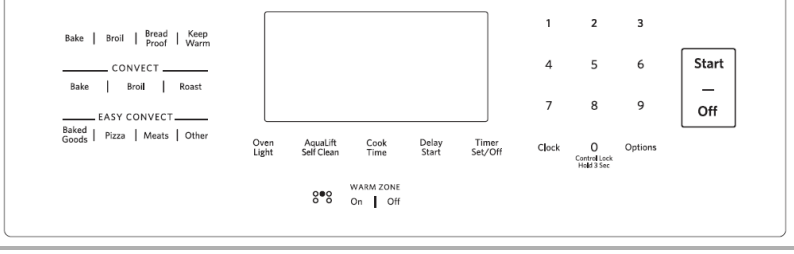
CLOCK
This clock can use a 12- or 24-hour cycle. See “Electronic Oven Controls” section.
1. Press CLOCK.
2. Press “3” for AM or “6” for PM.
3. Press the number keypads to set the time of day.
4. Press CLOCK or START.
Oven LIGHT
Oven cavity light
While the oven door is closed, press the OVEN LIGHT keypad to turn the light on and off. The oven light will come on when the oven door is opened.
TIMER SET/OFF
Oven timer
The Timer can be set in hours or minutes up to 9 hours and 59 minutes.
1. Press TIMER SET/OFF.
2. Press the number keypads to set the length of time in hr-hr-min-min. Leading zeroes do not have to be entered. For example, for 2 minutes, enter “2.”
3. Press TIMER SET/OFF to begin the countdown. If enabled, end-of-cycle tones will sound at end of countdown.
4. Press TIMER SET/OFF to cancel the Timer and return to the time of day. Do not press the OFF keypad because the oven will turn off.
5. If the Kitchen Timer is running, but not in the display, press KITCHEN TIMER to display the countdown for 5 seconds.
START
Cooking start
The Start keypad begins any oven function. If Start is not pressed within 2 minutes after pressing a keypad, the function is canceled and the time of day is displayed.
OFF
Range function
The Off keypad stops any oven function except the Clock, Timer, Control Lock, and Warm Zone.
BAKE
Baking and roasting
1. Press BAKE.
2. Press the number keypads to set the desired temperature. If the temperature entered is not in the range of the temperatures allowed, the minimum or maximum allowed temperature will be displayed. Enter a temperature in the allowable range.
3. Press START.
4. To change the temperature, repeat steps 1 and 2. Press START for the change to take effect.
5. Press OFF when finished.
BROIL
1. Press BROIL.
2. Select the broiling temperature by pressing 1 - high (500°F [260°C]), 2 - medium (450° F [232°C]) or 3 - low (400°F [204°C]). The default setting is high.
3. Press STARTand allow the oven to preheat for 5 minutes.
4. Position the cookware in the oven and leave the door open 6" (15 cm) at the broil stop position.
5. Press OFF when finished
CONVECT BAKE
Convection cooking
1. Press CONVECT BAKE.
2. Press the number keypads to set the desired temperature. If the temperature entered is not in the range of the temperatures allowed, the minimum or maximum allowed temperature will be displayed. Enter a temperature in the allowable range.
3. Press START.
4. To change the temperature, repeat step 2. Press START for the change to take effect.
5. Press OFF when finished.
CONVECT ROAST
Convection cooking
1. Press CONVECT ROAST.
2. Press the number keypads to set the desired temperature. If the temperature entered is not in the range of the temperatures allowed, the minimum or maximum allowed temperature will be displayed. Enter a temperature in the allowable range.
3. Press START.
4. To change the temperature, repeat step 2. Press START for the change to take effect.
5. Press OFF when finished.
CONVECT BROIL
Convection cooking
1. Press CONVECT BROIL.
2. Press the number keypads to set the desired temperature. If the temperature entered is not in the range of the temperatures allowed, the minimum or maximum allowed temperature will be displayed. Enter a temperature in the allowable range.
3. Press STARTand leave the door closed.
4. To change the temperature, repeat Step 2. Press START for the change to take effect.
5. Press OFF when finished.
EASYCONVECT™ CONVERSION
Recipe conversion for convection cooking
NOTE: For best results, preheat your oven to the required temperature prior to using EasyConvect™ Conversion. After preheating is complete, press OFF before using EasyConvect™ Conversion.
1. Press the appropriate EasyConvect™ keypad (MEATS, PIZZA, BAKED GOODS or OTHER).
2. Press START.
3. Press the number keypads to enter the standard cook temperature, and then press START.
4. Enter the standard cook time, and then press START.
5. Place food in the oven at the appropriate time. Check food for doneness before the stop time is reached. If food will not be done when stop time is reached, add more cooking time before time elapses. See the “Cook Time” section. At the end of the stop time, the oven will automatically turn off.
6. Press OFF when finished. Refer to the “EasyConvect™ Conversion” section for more information
BREAD PROOF
Recipe conversion for convection cooking
1. Press BREAD PROOF until the desired proof is displayed (“Standard Proof” or “Rapid Proof”).
2. Press START. Let the dough rise until nearly doubled in size. Proofing time may vary depending on dough type and quantity.
3. Press OFF when finished proofing.
Refer to the “Proofing Bread” section for more information.
KEEP WARM
Hold warm
Food must be at serving temperature before placing it in the warmed oven.
1. Press KEEP WARM.
2. Press the number keypads to set the desired temperature. If the temperature entered is not in the range of the temperatures allowed, the minimum or maximum allowed temperature will be displayed. Enter a temperature in the allowable range.
3. Press START.
4. Press OFF when finished.
DELAY START
The Delay Start keypad is used to enter the starting time for an oven function with a delayed start. Delay Start should not be used for foods such as breads and cakes because they may not bake properly. To set a Cook Time or a Delayed Cook Time, see “Cook Time” section.
COOK TIME
Timed cooking
Cook Time allows the oven to be set to turn on at a certain time of day, cook for a set length of time, and/or shut off automatically. To set a Timed Cook or a Delayed Timed Cook, see “Cook Time” section.
WARMING ZONE ON/OFF
Warming zone
Press WARMING ZONE ON to select the warming element on the cooktop, then press START.
Press WARMING ZONE OFF to turn off the warming element.
AQUALIFT SELF CLEAN
Aqualift® selfclean cycle
See the “Clean Cycle” section in the Owner’s Manual.
CONTROL LOCK hold 3 sec. to lock
Oven control lockout
No keypads will function with the controls locked.
1. Check that the oven and the Kitchen Timer are off.
2. Press and hold CONTROL LOCK keypad for 3 seconds.
3. If enabled, a tone will sound, and “CONTROL LOCKED” will be displayed.
4. Repeat to unlock.
OPTIONS
Oven use functions
Enables you to personalize the audible tones and oven operation to suit your needs. See the “Oven Use” section.
Cooktop Use
WARNING Fire Hazard Turn off all controls when done cooking. Failure to do so could result in death or fire
Ceramic Glass
The surface cooking area will glow red when an element is on. Some parts of the surface cooking area may not glow red when an element is on. This is normal operation. It will also randomly cycle off and back on again, even while on High, to keep the cooktop from extreme temperatures. It is normal for the surface of ceramic glass to appear to change color when surface cooking areas are hot. As the glass cools, it will return to its original color.
Clean the cooktop after each use to help avoid scratches, pitting, abrasions and to condition the glass surface. Ceramic glass cooktop cleaner and a cooktop scraper are also recommended for stubborn soils. Do not use abrasive cleaners, cleaning pads or harsh chemicals for cleaning. The Cooktop Care Kit Part Number 31605 contains all of the items needed to clean and condition your ceramic glass cooktop. Refer to the “Range Maintenance and Care” section in the Owner’s Manual for additional information.
IMPORTANT: To avoid permanent damage to the cooktop surface and to make soils easier to remove, clean the cooktop after each use to remove all soils.
- For cooktops with two dual elements in the front positions, the fastest boiling performance for pots 10" (25.4 cm) and larger will be on the larger dual element with both elements on “Dual Hi.” For best low heat performance on pans 10" (25.4 cm) and larger, use the smaller dual element set at “Single Lo.”
- For best melting performance with small pans, use the EvenHeat™ element.
- Use flat-bottomed cookware for best heat conduction and energy efficiency. Cookware with rounded, warped, ribbed or dented bottoms could cause uneven heating and poor cooking results.
- Determine flatness by placing the straight edge of a ruler across the bottom of the cookware. While you rotate the ruler, no space or light should be visible between it and the cookware.
- Cookware designed with slightly indented bottoms or small expansion channels can be used.
- Make sure the bottoms of pots and pans are clean and dry before using them. Residue and water can leave deposits when heated.
- Avoid storing jars or cans above the cooktop. Dropping a heavy or hard object onto the cooktop could crack the cooktop.
- To avoid damage to the cooktop, do not leave a hot lid on the cooktop. As the cooktop cools, air can become trapped between the lid and the cooktop, and the ceramic glass could break when the lid is removed.
- For foods containing sugar in any form, clean up all spills and soils as soon as possible. Allow the cooktop to cool down slightly. Then, while wearing oven mitts, remove the spills using a scraper while the surface is still warm. If sugary spills are allowed to cool down, they can adhere to the cooktop and can cause pitting and permanent marks.
- To avoid scratches, do not slide cookware or bakeware across the cooktop. Aluminum or copper bottoms and rough finishes on cookware or bakeware could leave scratches or marks on the cooktop.
- Do not cook popcorn in prepackaged aluminum containers on the cooktop. They could leave aluminum marks that cannot be removed completely.
- To avoid damage to the cooktop, do not allow objects that could melt, such as plastic or aluminum foil, to touch any part of the entire cooktop.
- To avoid damage to the cooktop, do not use the cooktop as a cutting board.
- To avoid damage to the cooktop, do not cook foods directly on the cooktop.
Cooktop On Indicator Light
The Cooktop On indicator light is located on the console panel. When any control knob/cooktop element on the console panel is turned on, the Cooktop On indicator light will glow.
Hot Surface Indicator Light
On ceramic glass models, the hot surface indicator light is located on the console panel. The hot surface indicator light will glow as long as any surface cooking area is too hot to touch, even after the surface cooking area is turned off.
OVEN USE
Odors and smoke are normal when the oven is used the first few times or when it is heavily soiled.
IMPORTANT: The health of some birds is extremely sensitive to the fumes given off. Exposure to the fumes may result in death to certain birds. Always move birds to another closed and well ventilated room.
Electronic Oven Controls
Control Display
The display will light up when first powered up or after a power loss. When oven is not in use, the time of day is displayed.
Tones
Tones are audible signals, indicating the following:
One Tone
- Valid pad press
- Oven is preheated (long tone).
- Kitchen timer (long tone with a reminder tone every 60 seconds).
- Function has been entered.
Three Tones
Four Tones
End of cycle (with a reminder tone every 60 seconds). Use the Options key to change the tone settings.
Options
Many features of the oven control can be adjusted to meet your personal needs. These changes are made using the Options keypad.
Use the Options keypad to scroll through the features that can be changed. Each press of the Options keypad will advance the display to the next setting. After selecting the feature to be changed, the control will prompt you for the required input. Details of all of the feature changes are explained in the following sections.
Press OFF to exit Options.
Fahrenheit and Celsius
The temperature is preset at Fahrenheit, but can be changed to Celsius. To change:
1. Press OPTIONS until “TEMP UNIT” is displayed.
2. The current setting will be displayed.
3. Press the “1” keypad to adjust the setting.
4. Press OFF to save the setting and display the time of day.
Audible Tones Disable
Turns off all tones, including the end of cycle tone and key press tones.
1. Press OPTIONS until “SOUND” is displayed.
2. The current setting will be displayed.
3. Press the “1” keypad to adjust the setting.
4. Press OFF to save the setting and display the time of day.
Sound Volume
Sets the pitch of the tone to either high or low.
1. Press OPTIONS until “SOUND VOLUME” is displayed.
2. The current setting will be displayed.
3. Press the “1” keypad to adjust the setting.
4. Press OFF to save the setting and display the time of day.
End of Cycle Tone
Activates or turns off the tones that sound at the end of a cycle.
1. Press OPTIONS until “END TONE” is displayed.
2. The current setting will be displayed.
3. Press the “1” keypad to adjust the setting.
4. Press OFF to save the setting and display the time of day.
Reminder Tones Disable
Turns off the short repeating tone that sounds every 1 minute after the end of cycle tones.
1. Press OPTIONS until “REMINDER TONE” is displayed.
2. The current setting will be displayed.
3. Press the “1” keypad to adjust the setting.
4. Press OFF to save the setting and display the time of day.
Key Press Tones
Activates or turns off the tones when a keypad is pressed.
1. Press OPTIONS until “KEYPRESS TONE” is displayed.
2. The current setting will be displayed.
3. Press the “1” keypad to adjust the setting.
4. Press OFF to save the setting and display the time of day.
Demo Mode
IMPORTANT: This feature is intended for use on the sales floor with 120 V power connection and permits the control features to be demonstrated without heating elements turning on. If this feature is activated, the oven will not work.
1. Press OPTIONS until “DEMO MODE” is displayed.
2. The current setting will be displayed.
3. Press the “1” keypad to adjust the setting.
4. Press OFF to save the setting and display the time of day.
12-Hour Shutoff
The oven control is set to automatically shut off the oven 12 hours after the oven initiates a cook or clean function. This will not interfere with any timed or delay cook functions.
1. Press OPTIONS until “12 HR AUTO OFF” is displayed.
2. The current setting will be displayed.
3. Press the “1” keypad to adjust the setting.
4. Press OFF to save the setting and display the time of day.
12/24 Hour Clock
1. Press OPTIONS until “12/24 HOUR” is displayed.
2. The current setting will be displayed.
3. Press the “1” keypad to adjust the setting.
4. Press OFF to save the setting and display the time of day.
Languages - Scrolling Display Text
Language options are English, Spanish and French.
1. Press OPTIONS until “LANGUAGE” is displayed.
2. The current setting will be displayed.
3. Press the number keypads to adjust the setting.
4. Press OFF to save the setting and display the time of day.
Energy Save
The Energy Save mode deactivates the display to reduce energy consumption.
1. Press OPTIONS until “ENERGY SAVE” is displayed.
2. The current setting will be displayed.
3. Press the “1” keypad to adjust the setting.
4. Press OFF to save the setting and display the time of day.