3-866-957-12(1)
Stereo Power
Amplifier
1999 by Sony Corporation
TA-N1
Operating Instructions
Mode d’emploi
GB
FR
2
GB
WARNING
To prevent fire or shock
hazard, do not expose the
unit to rain or moisture.
To avoid electrical shock,
do not open the cabinet.
Refer servicing to qualified
personnel only.
Do not install the
appliance in a confined
space, such as a bookcase
or built-in cabinet.
For the customers in United States
This symbol is intended to alert the user to
the presence of uninsulated “dangerous
voltage” within the product’s enclosure
that may be of sufficient magnitude to
constitute a risk of electric shock to
persons.
This symbol is intended to alert the user to
the presence of important operating and
maintenance (servicing) instructions in the
literature accompanying the appliance.
CAUTION
You are cautioned that any changes or
modification not expressly approved in
this manual could void your authority to
operate this equipment.
Owner’s Record
The model and serial numbers are located
on the rear of the unit. Record the serial
number in the space provided below.
Refer to them whenever you call upon
your Sony dealer regarding this product.
Model No. TA-N1
Serial No.
For the customers in Canada
CAUTION
TO PREVENT ELECTRIC SHOCK, DO
NOT USE THIS POLARIZED AC PLUG
WITH AN EXTENSION CORD,
RECEPTACLE OR OTHER OUTLET
UNLESS THE BLADES CAN BE FULLY
INSERTED TO PREVENT BLADE
EXPOSURE.

3
GB
GB
About This Manual
The instructions in this manual are for model TA-N1.
Check your model number by looking at the front panel.
In this manual, the European model is used for
illustration purposes unless stated otherwise. Any
difference in operation is clearly indicated in the text, for
example, “USA/Canada only.”
Convention
The following icon is used in this manual:
z Indicates hints and tips for making the task easier.
TABLE OF CONTENTS
Hooking Up the Components 4
Unpacking 4
Preamplifier Hookups
(Unbalanced Connections) 5
Preamplifier Hookups (Balanced Connections) 6
Speaker Hookups (Standard Connections) 7
Speaker Hookups (Bi-wired connections) 8
Power Connections 9
Location of Parts and Basic
Operations 10
Front Panel Parts Description 10
Rear Panel Parts Description 12
Additional Information 13
Precautions 13
Troubleshooting 14
Specifications 15

4
GB
Hooking Up
the
Components
This chapter describes how to connect
a Sony TA-E1 preamplifier, your
speakers, and your other audio
components to the power amplifier.
Be sure to read this section before
making any connections.
Unpacking
Check that you received the following items:
• AC power cord (1)
• AC power plug adapter (3 to 2 prong polarized type) (1)
(USA/Canada only)
Before you get started
• Turn off the power to all components before making
any connections.
• Do not connect the AC power cord until all of the
connections are completed.
• Be sure to make connections firmly to avoid hum and
noise.
• When connecting an audio cord, be sure to match the
color-coded pins to the appropriate jacks on the
components: white (left) to white; and red (right) to
red.
5
GB
Hooking Up the Components
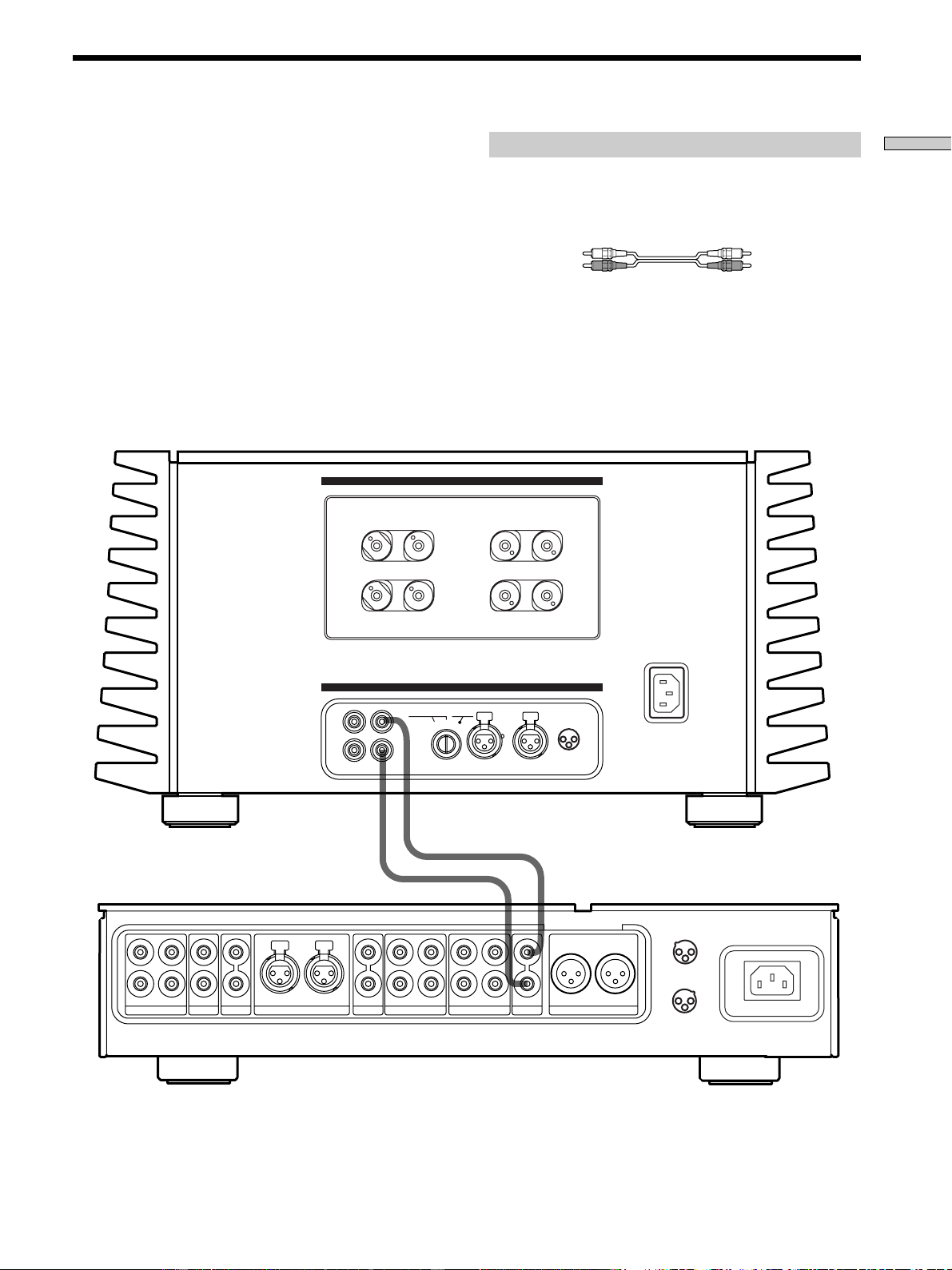
Preamplifier Hookups (Unbalanced Connections)
Connect the preamplifier you are using (Sony TA-E1, etc.)
to the power amplifier’s UNBALANCED 1 or
UNBALANCED 2 input jacks. For details, refer to the
instructions supplied with the preamplifier.
L
R
L
R
2
R
1
SACDCDLINE BALANCED LINE
OUT I N
TAPE2/MD
DIRECT
PRE OUT
L
OUT I N
TAPE1/DAT
R
BALANCED OUT
L
1
3
1 :GROUND
2 :HOT ( + )
3 :COLD ( – )
2
CONNECTION
ASSIGNMENT
2
3
1 :GROUND
2 :HOT ( + )
3 :COLD ( – )
1
1
1
2
3
2
CONNECTION
ASSIGNMENT
BALANCEDINPUT SELECTOR
IMPEDANCE USE 4~16Ω
L
L
+
+
–
–
R
R
–
–
+
+
BALANCEDUNBALANCED
L
L
R
R
UNBALANCED
12
1 : GROUND
2 : HOT(+)
3 : COLD(–)
INPUT
SPEAKERS
A
+
B USE 8~16
Ω
–A–
–B–
Required cords
Audio cords (not supplied)
When connecting a cord, be sure to match the color-coded pins to
the appropriate jacks on the components.
White (L) White (L)
Red (R) Red (R)
TA-E1, etc.
TA-N1
6
GB
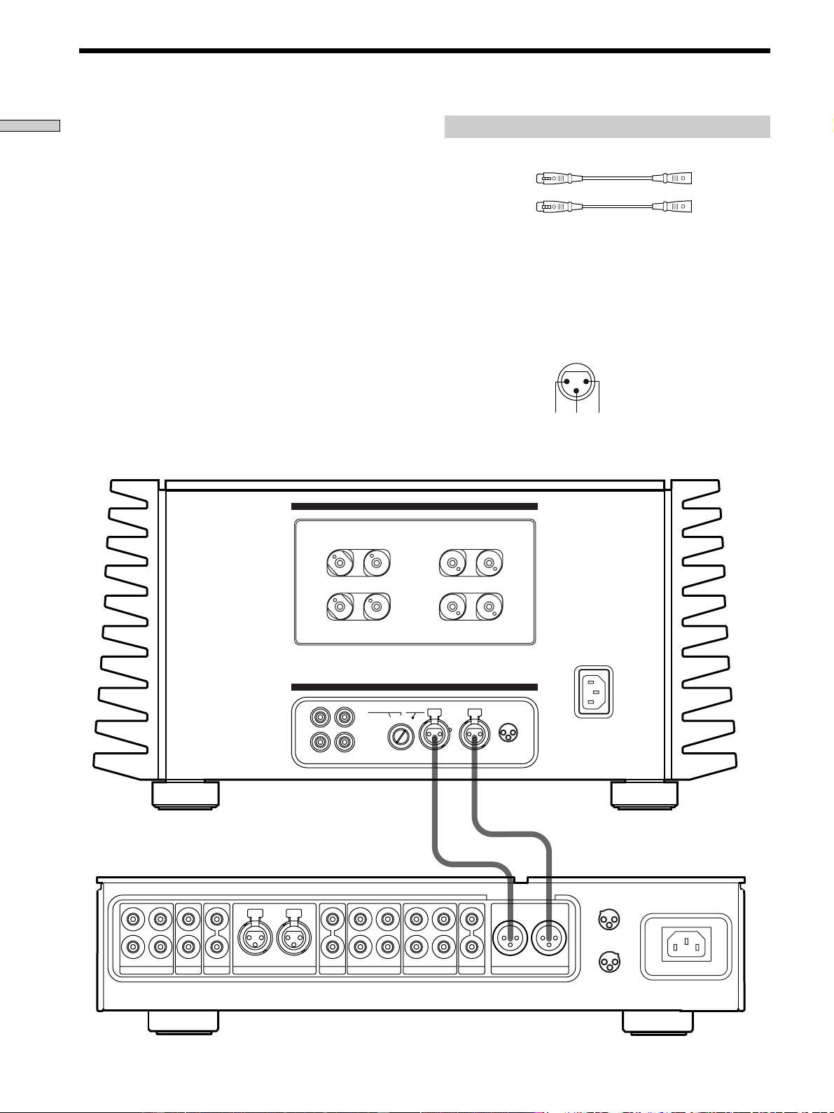
Hooking Up the Components
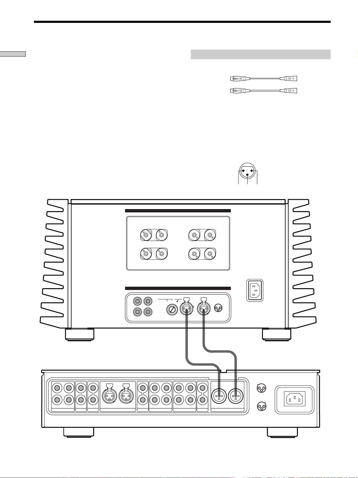
Connect the BALANCED output jacks on the preamplifier
you are using (Sony TA-E1, etc.) to the power amplifier’s
BALANCED jacks. For details, refer to the instructions
supplied with the preamplifier.
Preamplifier Hookups (Balanced Connections)
Required cords
Balanced cords (not supplied)
(L) (L)
(R) (R)
1: GROUND
2: HOT (+)
3: COLD (–)
L
R
L
R
2
R
1
SACDCDLINE BALANCED LINE
OUT I N
TAPE2/MD
DIRECT
PRE OUT
L
OUT I N
TAPE1/DAT
R
BALANCED OUT
L
1
3
1 :GROUND
2 :HOT ( + )
3 :COLD ( – )
2
CONNECTION
ASSIGNMENT
2
3
1 :GROUND
2 :HOT ( + )
3 :COLD ( – )
1
1
1
2
3
2
CONNECTION
ASSIGNMENT
BALANCEDINPUT SELECTOR
IMPEDANCE USE 4~16Ω
L
L
+
+
–
–
R
R
–
–
+
+
BALANCEDUNBALANCED
L
L
R
R
UNBALANCED
12
1 : GROUND
2 : HOT(+)
3 : COLD(–)
INPUT
SPEAKERS
A
+
B USE
8~16
Ω
–A–
–B–
TA-E1, etc.
TA-N1
Note
The pin assignment of the BALANCED input jacks on the
amplifier are 1:GROUND, 2:HOT, and 3:COLD. When
connections are made to a preamplifier with a pin assignment of
1:GROUND, 2:COLD, and 3:HOT, reverse the polarities (‘ and
’) of the speaker cords. For details, refer to the instructions
supplied with the preamplifier.
IN
2 3 1
7
GB
Hooking Up the Components
1
1
2
3
2
CONNECTION
ASSIGNMENT
BALANCEDINPUT SELECTOR
IMPEDANCE USE 4~16Ω
L
L
+
+
–
–
R
R
–
–
+
+
BALANCEDUNBALANCED
L
L
R
R
UNBALANCED
12
1 : GROUND
2 : HOT(+)
3 : COLD(–)
INPUT
SPEAKERS
A
+ B USE
8~16
Ω
–A–
–B–
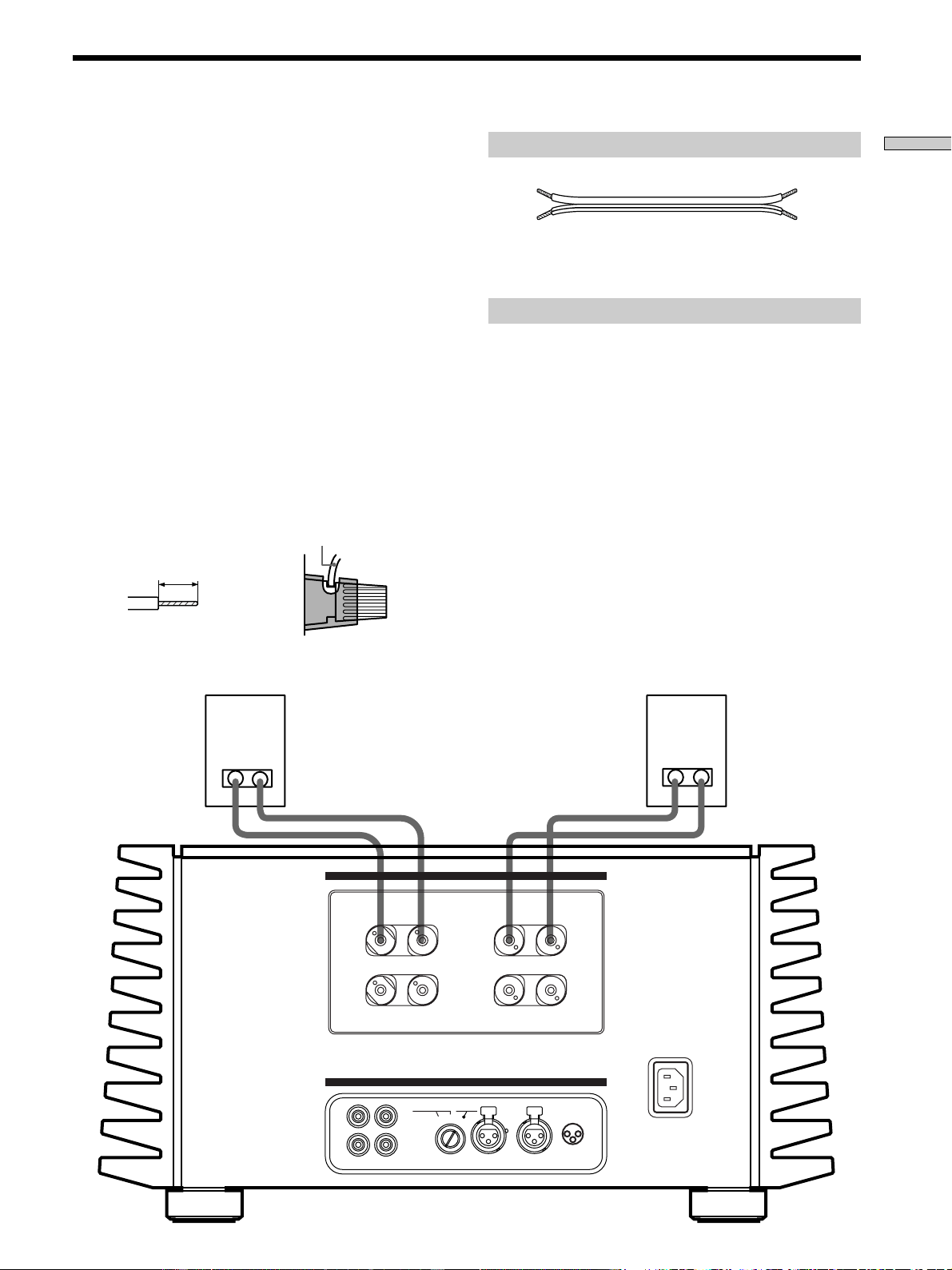
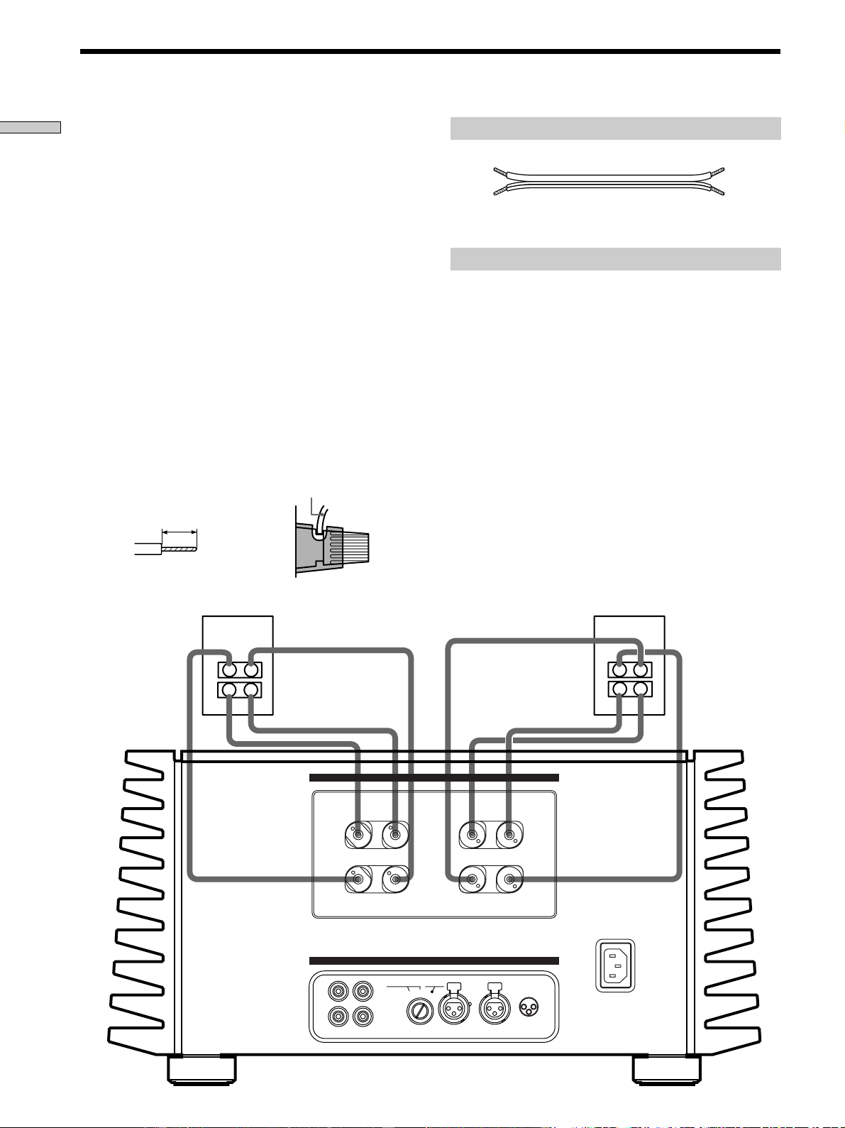
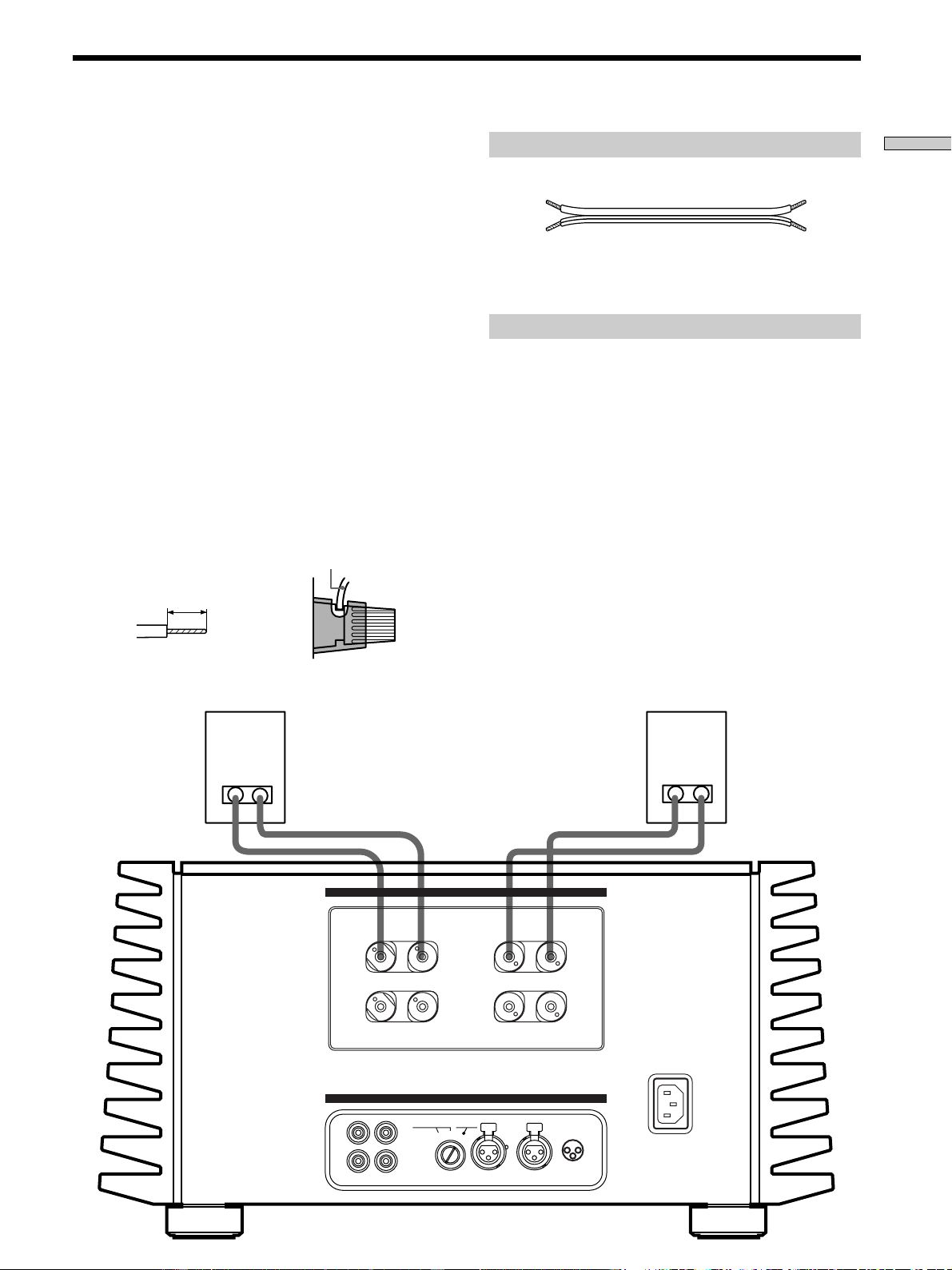
Speaker Hookups (Standard Connections)
Connect the jacks on the speakers to the SPEAKERS A or
B terminals on the power amplifier using a single speaker
cord for each speaker. There is no difference in the sound
output from SPEAKERS A and B. For details, refer to the
instructions supplied with the speakers.
Connecting the speaker cords
Caution
This is a high output amplifier. Touching the stripped
end of the speaker cords when the power is on may
result in injury.
• Be sure to check that the amplifier is turned off before
making any connections.
• Strip both ends of the speaker cords about 10 mm
(
3
/8 in.) and twist the wire strands of the cord together
(A).
• Insert each end of the speaker cord fully into the
speaker terminal.
Be sure the stripped portion of the speaker cord does
not protrude outside of the speaker terminal cover
(USA/Canada only) nor from the speaker terminal (B).
Required cords
Speaker cords (1 pair) (not supplied)
Connect the jacks on the speaker to the power amplifier’s
SPEAKERS A or B terminals.
Notes on speaker hookup
• Connect the right speaker to the “R” terminals, and
connect the left speaker to the “L” terminals.
• Be sure to match the ends of the speaker cord to the
appropriate terminal on the components: + to + and –
to –. If the cords are reversed, the sound will be
distorted and will lack bass.
• When the maximum input level of the speakers you are
using is low, try to avoid excessive power output from
this unit to the speakers by controlling the volume on
the preamplifier. Continuously playing an audio source
at a level that distorts the audio output may damage the
speakers.
• The speaker terminals on this unit are compatible with
Y lug jack connection (European model only).
10 mm
(
3
/8 in.)
speaker cord
A
B
(Speaker terminal cover is
on USA/Canadian models
only.)
8
GB
Hooking Up the Components
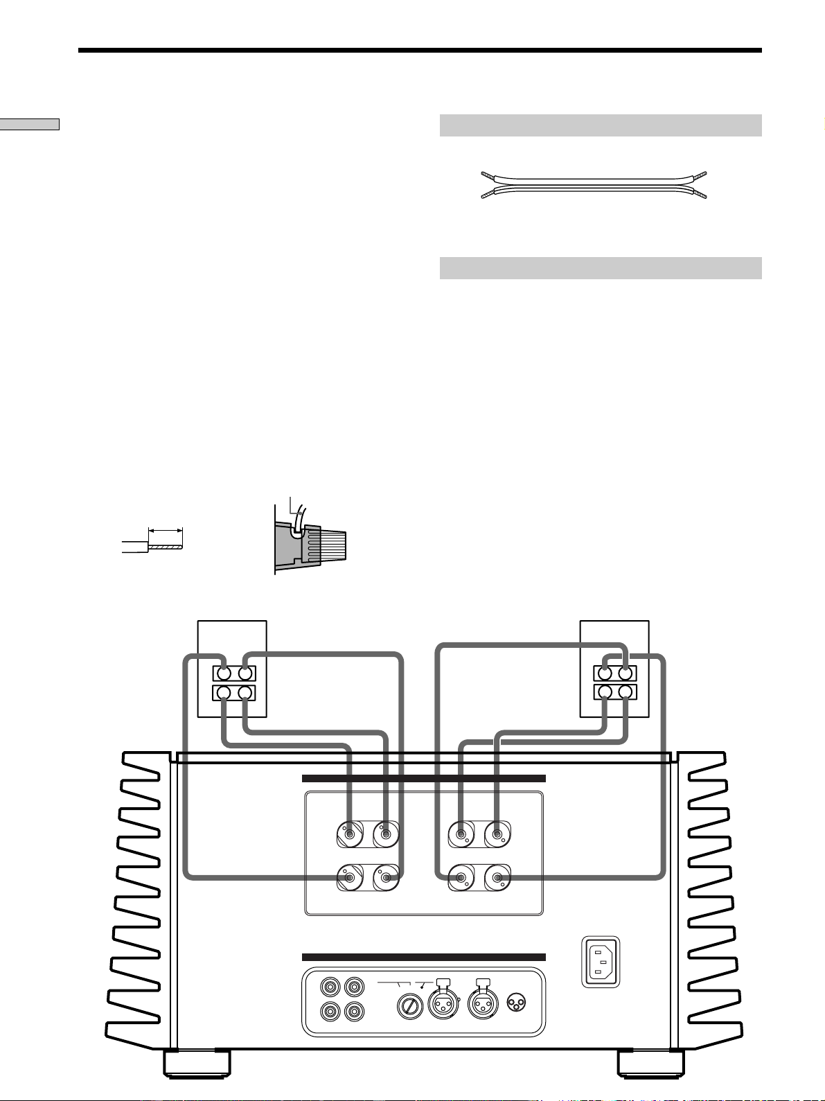
Speaker Hookups (Bi-wired Connections)
When the speakers you are making connections to can be
bi-wired, bi-wired connections can be made to this unit.
Connect the two sets of jacks on the speaker to the
SPEAKERS A and B terminals on this unit using two
speaker cords for each speaker. For details, refer to the
instructions supplied with the speakers.
Connecting the speaker cords
Caution
This is a high output amplifier. Touching the stripped
end of the speaker cords when the power is on may
result in injury.
• Be sure to check that the amplifier is turned off before
making any connections.
• Strip both ends of the speaker cords about 10 mm
(
3
/8 in.) and twist the wire strands of the cord together
(A).
• Insert each end of the speaker cord fully into the
speaker terminal.
Be sure the stripped portion of the speaker cord does
not protrude outside of the speaker terminal cover
(USA/Canada only) nor from the speaker terminal (B).
1
1
2
3
2
CONNECTION
ASSIGNMENT
BALANCEDINPUT SELECTOR
IMPEDANCE USE 4~16Ω
L
L
+
+
–
–
R
R
–
–
+
+
BALANCEDUNBALANCED
L
L
R
R
UNBALANCED
12
1 : GROUND
2 : HOT(+)
3 : COLD(–)
INPUT
SPEAKERS
A + B USE 8~16Ω
–A–
–B–
TA-N1
Required cords
Speaker cords (2 pair) (not supplied)
Connect the jacks on the speaker to the power amplifier’s
SPEAKERS A and B terminals.
Notes on speaker hookup
• Connect the right speaker to the “R” terminals, and
connect the left speaker to the “L” terminals.
• Be sure to match the ends of the speaker cord to the
appropriate terminal on the components: + to + and –
to –. If the cords are reversed, the sound will be
distorted and will lack bass.
• When the maximum input level of the speakers you are
using is low, try to avoid excessive power output from
this unit to the speakers by controlling the volume on
the preamplifier. Continuously playing an audio source
at a level that distorts the audio output may damage the
speakers.
• The speaker terminals on this unit are compatible with
Y lug jack connection (European model only).
z About bi-wired connections
Bi-wired connections can be carried out when the speaker has
two sets of input terminals that separate high and low frequency
audio signals.
10 mm
(
3
/8 in.)
speaker cord
A
B
(Speaker terminal cover is on
USA/Canadian models only.)
9
GB
Hooking Up the Components
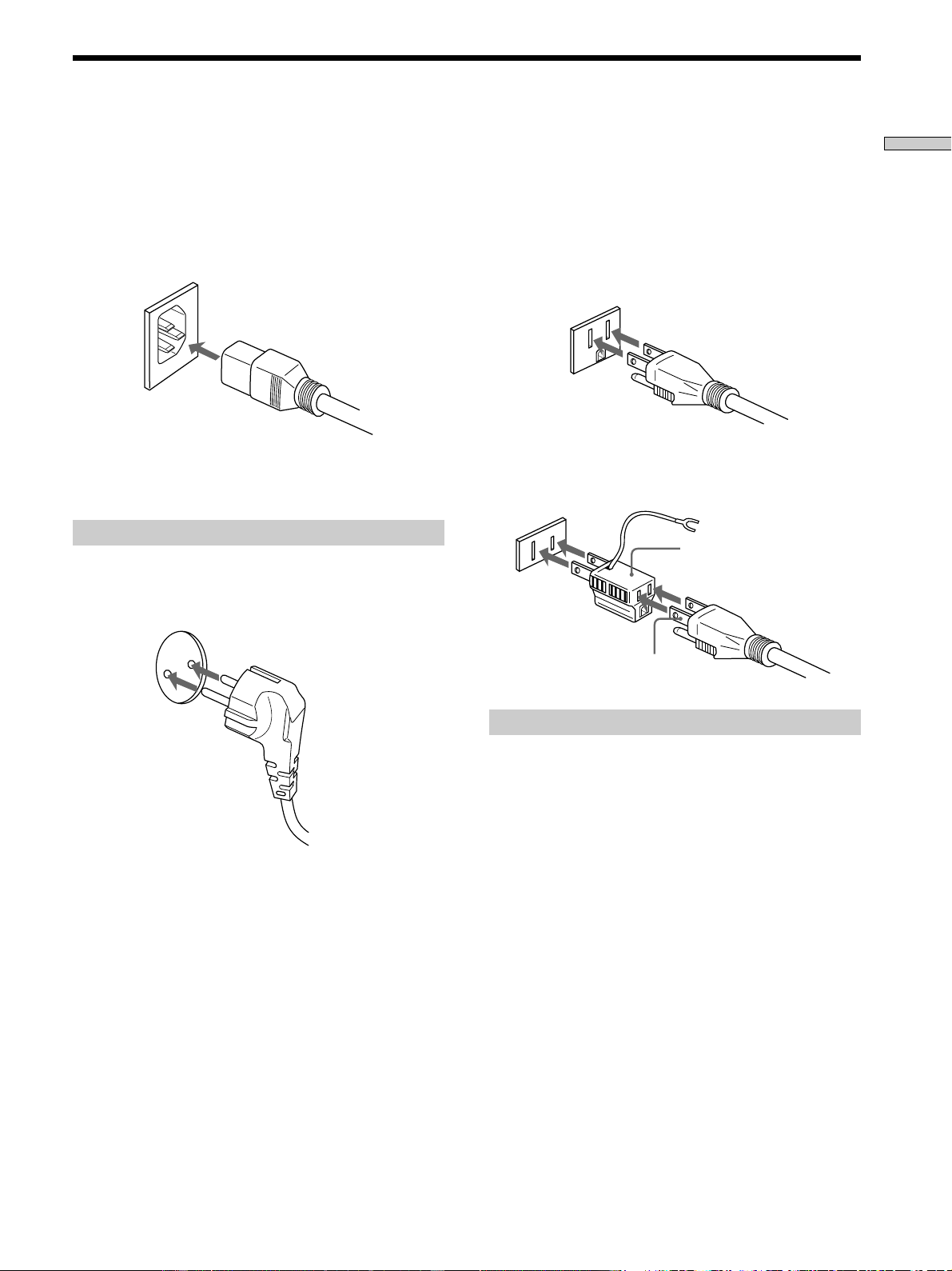
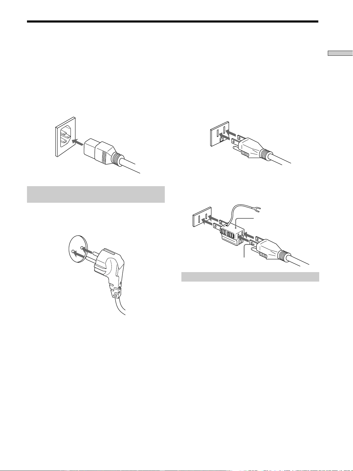
Power Hookup
Before connecting the AC power cord of this power
amplifier to a wall outlet:
• Make sure that the power switch on the power
amplifier is in the off position.
• Connect the speakers.
Connect the supplied power cord to the AC IN terminal
on this unit.
Connecting to the power outlet
(European model only)
Connect the supplied power cord to a wall outlet.
3-pronged grounded outlet
(USA/Canadian model only)
The supplied power cord has a 3-pronged grounded plug.
If you are using a 3-pronged grounded outlet, the plug
can be inserted directly into the outlet. However, if the
socket is a 2-pronged grounded outlet, use the supplied
AC power plug adapter or a commercially available AC
power plug adapter.
If noise (hum) is produced
Noise may be caused by an electrical potential difference on the
ground circuit*. In this case, use the supplied AC power plug
adapter and be careful not to connect the ground lead to
anything.
* Although the ground of the domestic outlet is normally a safety
ground, a slight electrical potential difference may be
produced, depending on the outlet. Therefore, use of the
supplied 3-pronged power cord may lessen the quality of the
audio signal or may produce humming noise.
Note
We recommend that you connect this unit directly to a wall
outlet. If you must use a multi-outlet tap, or extension cord, be
sure to use one capable of handling high current (at least 10 A) or
one designed for office use.
2-pronged polarized outlet
• When using a grounded outlet (the inlets are different sizes)
Use the supplied AC power plug adapter.
3 to 2 prong polarized
AC power plug adapter
N pole

10
GB
Front Panel Parts
Description
Location of
Parts and Basic
Operations
This chapter explains the names and
basic operations of the buttons and
controls located on the front and rear
panels.

11
GB
Location of Parts and Basic Operations
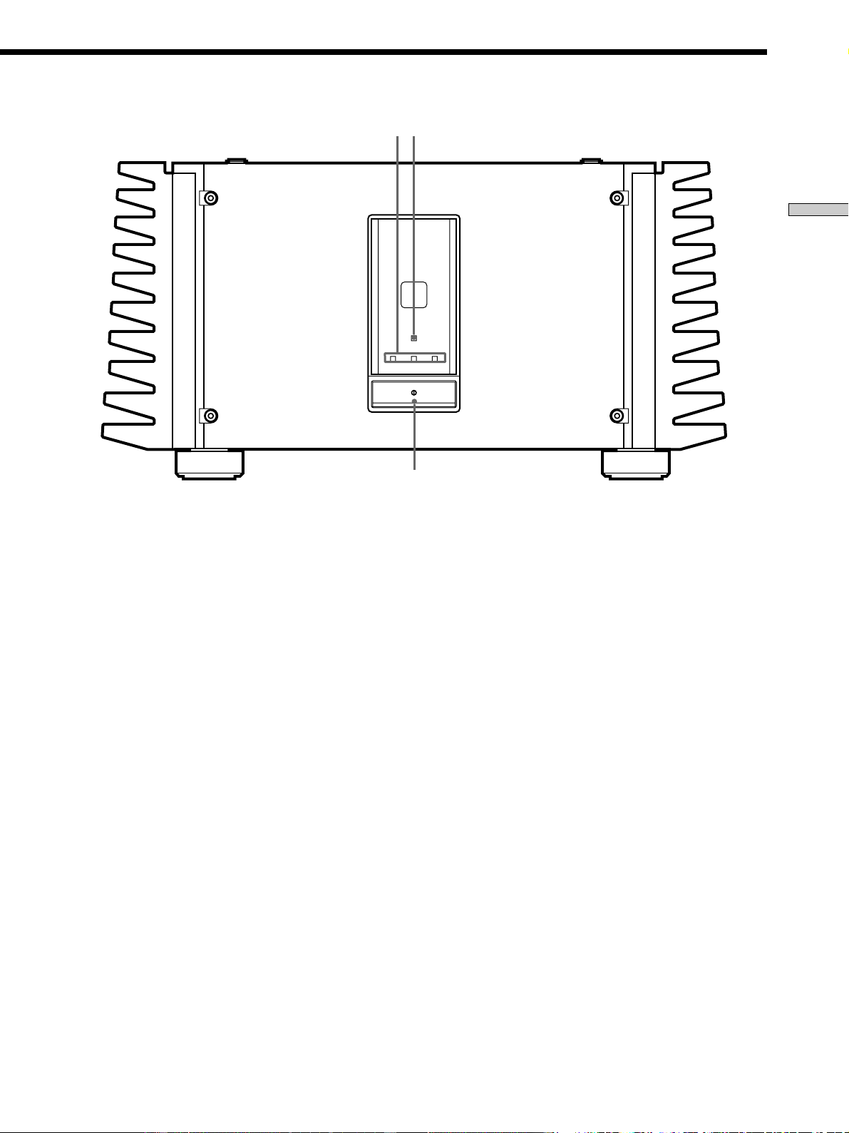
1 U (power) switch
Press to turn the power amplifier on and off.
• When turning the power on, turn down the volume on the
preamplifier to a minimum, then turn the preamplifier and
this unit on respectively. Similarly, when turning the power
off, turn down the volume on the preamplifier, then turn
the amplifier and preamplifier off respectively. This is done
to prevent damage to the speakers.
2 Input indicators (BALANCED/UNBALANCED 1/
UNBALANCED 2)
Light to indicate the input selected with the INPUT
SELECTOR control on the rear panel.
PROTECTION
BALANCED UNBALANCE UNBALANCE
12
1
23
3PROTECTION indicator
Lights for about 16 seconds after the power is turned
on. After that, the blue light above the indicator lights.
When there is a short circuit in one of the speakers, the
protection circuitry in this unit is automatically
activated. The PROTECTION indicator lights when
the protection circuitry is activated, and sound is not
produced from the speakers. Should this occur, turn
the power off, and check that the speakers connections
are correct.
12
GB
Location of Parts and Basic Operations
1
7 6
5
3
4
2
1
1
2
3
2
CONNECTION
ASSIGNMENT
BALANCEDINPUT SELECTOR
IMPEDANCE USE 4~16Ω
L
L
+
+
–
–
R
R
–
–
+
+
BALANCEDUNBALANCED
L
L
R
R
UNBALANCED
12
1 : GROUND
2 : HOT(+)
3 : COLD(–)
INPUT
SPEAKERS
A +
B USE 8~16Ω
–A–
–B–
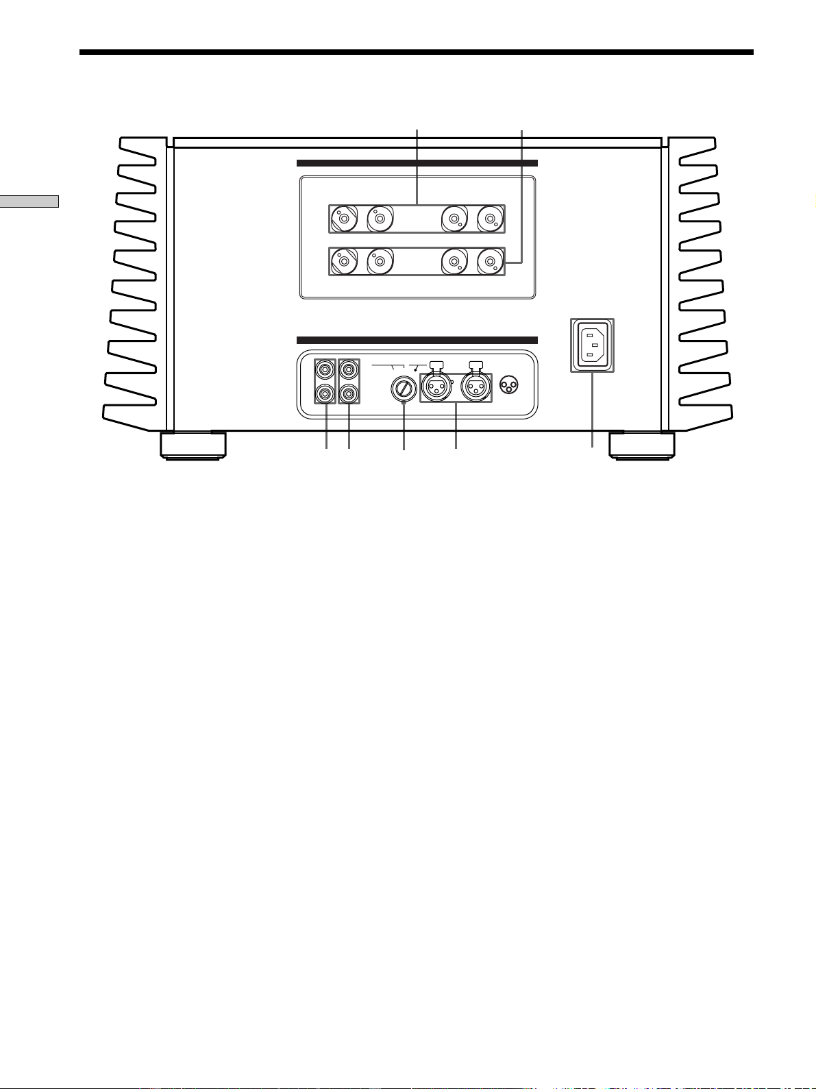
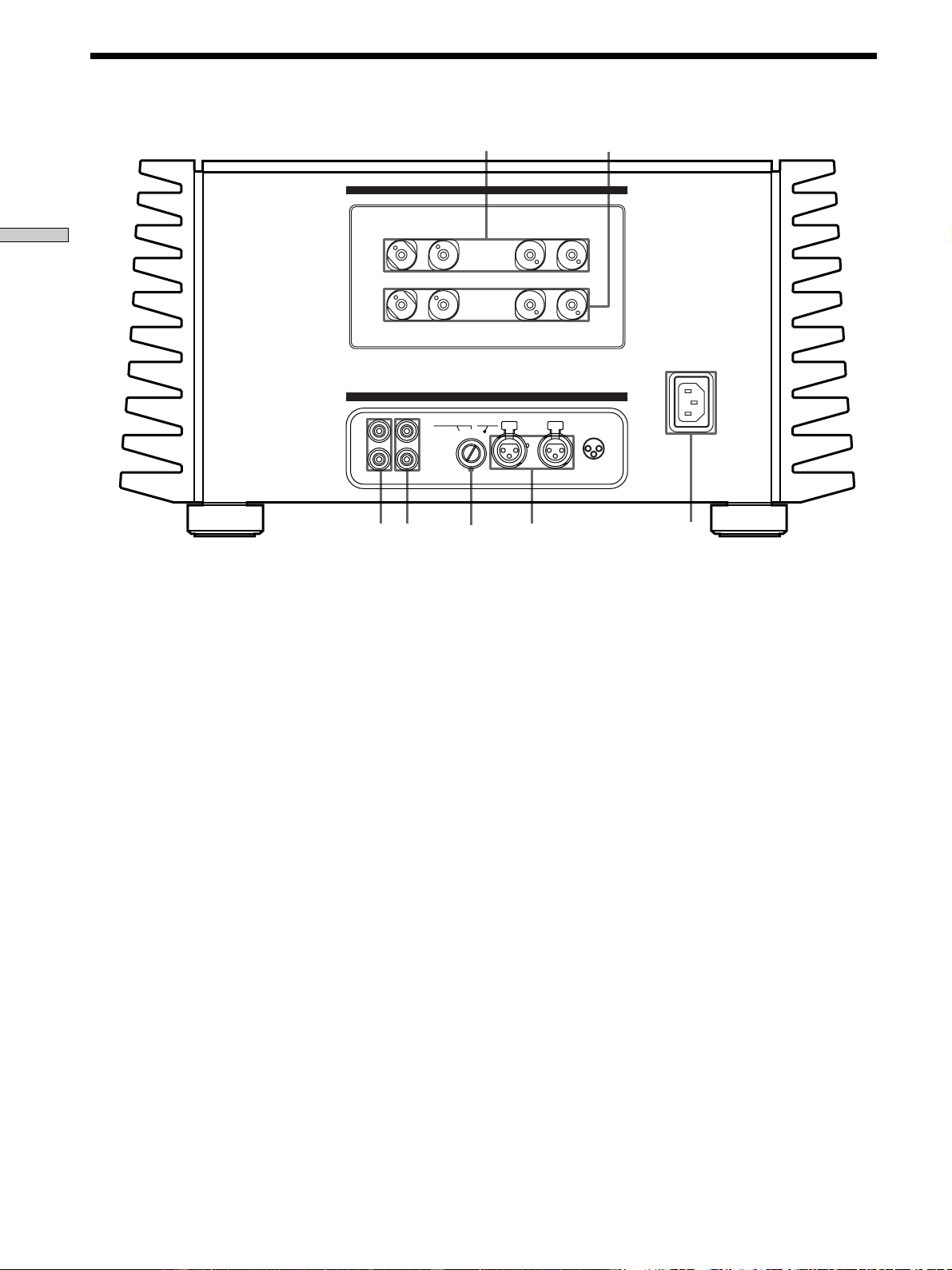
Rear Panel Parts Description
1 SPEAKERS A jacks
For details, see page 7.
2 SPEAKERS B jacks
Use with SPEAKERS A terminals when bi-wired
speaker connections are made (page 8).
3 AC IN terminal
Use to connect the supplied power cord to the AC IN
terminal to supply power to this unit from a wall
outlet.
4 BALANCED input jacks
Use to connect the BALANCED output jacks on a
preamplifier to this unit (page 6). Select BALANCED
with the INPUT SELECTOR knob (5).
5 INPUT SELECTOR control
Turn to select the input.
6 UNBALANCED 1 input jack
Use to connect the PRE OUT jacks on a preamplifier to
this unit (page 5). Select UNBALANCED 1 with the
INPUT SELECTOR knob (5).
7 UNBALANCED 2 input jack
Use to connect the PRE OUT jacks on a preamplifier to
this unit (page 5). Select UNBALANCED 2 with the
INPUT SELECTOR knob (5).

13
GB
Additional Information
Additional
Information
Precautions
On safety
Should any solid object or liquid fall into the cabinet,
unplug the power amplifier and have it checked by
qualified personnel before operating it any further.
On power sources
• Before operating the power amplifier, check that the
operating voltage is identical with your local power
supply. The operating voltage is indicated on the
nameplate at the rear of the power amplifier.
• If you are not going to use the power amplifier for a
long time, be sure to disconnect the power amplifier
from the wall outlet. To disconnect the AC power cord,
grasp the plug itself; never pull the cord.
• AC power cord must be changed only at the qualified
service shop.
On placement
• Place the power amplifier in a location with adequate
ventilation to prevent heat buildup and prolong the life
of the power amplifier.
• Do not place the power amplifier near heat sources, or
in a place subject to direct sunlight, excessive dust or
mechanical shock.
• Do not place anything on top of the cabinet that might
block the ventilation holes and cause malfunctions.
• Do not place the power amplifier:
– Any place that is not level or unstable.
– On top of a carpet or blanket.
– In an extremely cold place.
– Near a television or video deck.
(If used near a television or video deck, you may
experience noise in the audio and/or video signals.
The possibility of such interference greatly increases
when using an indoor TV antenna. We recommend
always using an external TV antenna.)
• Although this is a rationally designed stereo power
amplifier, it does emit an extremely large amount of
heat. Therefore, do not place anything on top of this
unit. Also, when using several of these units together
with high power connections, do not stack them
directly on top of one another. Either place each one on
an individual shelf of a rack, or place them side by side
horizontally.

14
GB
Additional Information
Troubleshooting
If you experience any of the following difficulties while
using the power amplifier, use this troubleshooting guide
to help you remedy the problem. Should any problem
persist, consult your nearest Sony dealer.
There’s no sound or only a very low-level sound
is heard.
/ Check that the speakers and components are
connected securely.
/ Make sure that all connections have been made
securely.
/ Make sure that you have selected the correct
component on the control amplifier.
The protection indicator does not go out or the
protection indicator lights and no sound is heard.
/ Turn off the power amplifier, check that there are
no short circuits in the speaker connections.
The left and right sounds are unbalanced or
reversed.
/ Check that the speakers and components are
connected correctly and securely.
/ Make sure all connections are made with the
correct polarity (+ and –).
Severe hum or noise is heard.
/ Check that the speakers and components are
connected securely.
/ Check that the connecting cords are away from a
transformer or motor, and at least 10 feet (3 meters)
away from a TV set or fluorescent light.
/ Move your TV away from the audio components.
/ The plugs and jacks are dirty. Wipe them with a
cloth slightly moistened with alcohol.
On heat emission during use
This unit will become very hot during use. This is not a
malfunction.
The entire surface of the cabinet will become quite hot,
especially when playing at high volumes. In such cases,
do not touch the cabinet. Touching the cabinet may cause
physical injury or fire.
In addition, do not use this unit in a completely enclosed
cabinet. Place it in a well ventilated location to prevent an
excessive rise in temperature.
On operation
Before connecting other components, be sure to turn off
and unplug the power amplifier.
On cleaning
Clean the cabinet, panel and controls with a soft cloth
slightly moistened with a mild detergent solution. Do not
use any type of abrasive pad, scouring powder or solvent
such as alcohol or benzine.
If you have any question or problem concerning your
power amplifier, please consult your nearest Sony dealer.
Precautions

15
GB
Additional Information
Specifications
AUDIO POWER SPECIFICATIONS
POWER OUTPUT AND TOTAL HARMONIC
DISTORTION:
With 8 ohm loads, both channels driven,
from 20 - 20,000 Hz; rated 200 watts per
channel minimum RMS power, with no
more than 0.05% total harmonic
distortion from 250 milliwatts to rated
output (USA model only).
Amplifier section
Power Output
200 W + 200 W (8 Ω)
400 W + 400 W (4 Ω)
Speaker Nominal Impedance:
4 Ω ∼ 16 Ω
Harmonic distortion
less than 0.005% (at 8 Ω, 10 W, THD)
Dumping factor
150 (at 8 Ω, 1 kHz)
Frequency response
5 Hz ~ 300 kHz + 0/– 1 dB (at 8 Ω, 1 W)
Input sensitivity and Impedance
1.5 V, 20 kΩ (Unbalanced)
1.5 V, 40 kΩ (Balanced)
Gain 28 dB
S/N more than 115 dB (Input shorted, A-Fil)
General
System Pure-complementary High Power Legato
Linear SEPP MOS FET power amplifier
Power requirements
USA and Canadian models
120 V AC, 60 Hz
European models
230 V AC, 50/60 Hz
Power consumption
USA and Canadian models
8.0 A
European models
600 W
Dimensions 480 × 245 × 530 mm
(18
7
/8 × 9
5
/8 × 20
7
/8 in.)
including projecting parts and controls
Mass (Approx.)
70 kg (154 lbs. 4 oz.)
Supplied accessories
See page 4.
Design and specifications are subject to change without
notice.

2
FR
AVERTISSEMENT
Afin d’éviter tout risque
d’incendie ou
d’électrocution, ne pas
exposer cet appareil à la
pluie ou à l’humidité.
Afin d’éviter tout risque
de choc électrique, ne pas
ouvrir le coffret. Confier
toute réparation à un
technicien qualifié
uniquement.
N’installez pas l’appareil
dans un espace confiné
comme dans une
bibliothèque ou un
meuble encastré.
A l’attention de la clientèle canadienne
ATTENTION:
POUR PREVENIR LES CHOCS
ELECTRIQUES, NE PAS UTILISER CETTE
FICHE POLARISEE AVEC UN
PROLONGATEUR, UNE PRISE DE
COURANT OU UNE AUTRE SORTIE DE
COURANT, SAUF SI LES LAMES
PEUVENT ETRE INSEREES A FOND
SANS EN LAISSER AUCUNE PARTIE A
DECOUVERT.

3
FR
FR
Au sujet de ce mode
d’emploi
Les instructions de ce mode d’emploi couvrent le modèle
TA-N1. Vérifiez le numéro de votre modèle sur le
panneau avant. Dans ce manuel, les illustrations
représentent le modèle européen, sauf mention contraire.
Toute différence de fonctionnement est clairement
indiquée dans le texte, par exemple, “Etats-Unis/Canada
seulement”.
Convention
L’icône suivante est utilisée dans ce mode d’emploi :
z Indique des conseils et suggestions pouvant faciliter
certaines opérations.
TABLE DES MATIÈRES
Raccordement des appareils 4
Déballage 4
Raccordement d’un préamplificateur (liaisons
asymétriques) 5
Raccordement d’un préamplificateur (liaisons
symétriques) 6
Raccordement des enceintes (liaisons standard) 7
Raccordement des enceintes (liaisons doubles) 8
Raccordement de l’alimentation 9
Nomenclature et opérations
élémentaires 10
Description des éléments du panneau avant 10
Description des éléments du panneau arrière 12
Informations complémentaires 13
Précautions 13
Guide de dépannage 14
Spécifications 15

4
FR
Raccordement
des appareils
Ce chapitre explique comment
raccorder un préamplificateur Sony
TA-E1, vos enceintes et vos autres
appareils audio à l’amplificateur de
puissance. Veuillez lire attentivement
ce paragraphe avant d’effectuer les
liaisons.
Déballage
Vérifiez si les accessoires suivants se trouvent bien dans le
carton d’emballage.
• Cordon d’alimentation secteur (1)
• Adaptateur de prise d’alimentation secteur (type
polarisé 3 à 2 broches) (1)
(Etats-Unis/Canada seulement)
Avant de commencer
• Mettez tous les appareils hors tension avant d’effectuer
les liaisons.
• Ne raccordez les cordons d’alimentation secteur que
lorsque toutes les liaisons sont terminées.
• Enfoncez les fiches à fond dans les prises pour éviter
tout bourdonnement et bruit.
• Lorsque vous raccordez un cordon audio, branchez les
fiches sur les prises de même couleur : blanc (gauche) à
blanc et rouge (droit) à rouge.

5
FR
Raccordement des appareils
Raccordement d’un préamplificateur (liaisons asymétriques)
Raccordez le préamplificateur que vous utilisez (Sony
TA-E1, etc.) aux prises d’entrée UNBALANCED 1 ou
UNBALANCED 2 de l’amplificateur de puissance. Pour
les détails, voir le mode d’emploi fourni avec le
préamplificateur.
L
R
L
R
2
R
1
SACDCDLINE BALANCED LINE
OUT I N
TAPE2/MD
DIRECT
PRE OUT
L
OUT I N
TAPE1/DAT
R
BALANCED OUT
L
1
3
1 :GROUND
2 :HOT ( + )
3 :COLD ( – )
2
CONNECTION
ASSIGNMENT
2
3
1 :GROUND
2 :HOT ( + )
3 :COLD ( – )
1
1
1
2
3
2
CONNECTION
ASSIGNMENT
BALANCEDINPUT SELECTOR
IMPEDANCE USE 4~16Ω
L
L
+
+
–
–
R
R
–
–
+
+
BALANCEDUNBALANCED
L
L
R
R
UNBALANCED
12
1 : GROUND
2 : HOT(+)
3 : COLD(–)
INPUT
SPEAKERS
A
+
B USE 8~16
Ω
–A–
–B–
Cordons nécessaires
Cordons audio (non fournis)
Lorsque vous raccordez un cordon, veillez à brancher les fiches
sur les prises appropriées sur les appareils.
TA-E1, etc.
TA-N1
Blanc (gauche) Blanc (gauche)
Rouge (droite) Rouge (droite)
6
FR
Raccordement des appareils
Raccordement d’un préamplificateur (liaisons symétriques)
Cordons nécessaires
Cordons symétriques (non fournis)
(L) (L)
(R) (R)
1: GROUND
2: HOT (+)
3: COLD (–)
L
R
L
R
2
R
1
SACDCDLINE BALANCED LINE
OUT I N
TAPE2/MD
DIRECT
PRE OUT
L
OUT I N
TAPE1/DAT
R
BALANCED OUT
L
1
3
1 :GROUND
2 :HOT ( + )
3 :COLD ( – )
2
CONNECTION
ASSIGNMENT
2
3
1 :GROUND
2 :HOT ( + )
3 :COLD ( – )
1
1
1
2
3
2
CONNECTION
ASSIGNMENT
BALANCEDINPUT SELECTOR
IMPEDANCE USE 4~16Ω
L
L
+
+
–
–
R
R
–
–
+
+
BALANCEDUNBALANCED
L
L
R
R
UNBALANCED
12
1 : GROUND
2 : HOT(+)
3 : COLD(–)
INPUT
SPEAKERS
A
+
B USE
8~16
Ω
–A–
–B–
TA-E1, etc.
TA-N1
Remarque
L’affectation des broches des prises de sortie BALANCED sur
l’amplificateur est 1 : GROUND, 2 : HOT et 3 : COLD. Si vous
raccordez l’amplificateur à un préamplificateur dont l’affectation
des fiches est 1 : GROUND, 2 : COLD et 3 : HOT, inversez la
polarité (‘ et ’) des cordons d’enceintes. Pour les détails,
reportez-vous au mode d’emploi du préamplificateur.
IN
2 3 1
Reliez les prises de sortie BALANCED du
préamplificateur que vous utilisez (Sony TA-E1, etc.) aux
prises d’entrée BALANCED de l’amplificateur de
puissance. Pour les détails, voir le mode d’emploi fourni
avec le préamplificateur.
7
FR
Raccordement des appareils
Raccordement des enceintes (liaisons standard)
Reliez les bornes d’enceintes aux bornes SPEAKERS A ou
B de l’amplificateur de puissance à l’aide d’un seul cordon
pour chaque enceinte. Il n’y a pas de différence entre le
son fourni par SPEAKERS A et celui fourni par
SPEAKERS B. Pour les détails, reportez-vous au mode
d’emploi des enceintes.
Raccordement des cordons d’enceintes
Cet appareil est un amplificateur à puissance de sortie
élevée. Vous pouvez vous blesser en touchant
l’extrémité dénudée des cordons d’enceintes lorsque
l’amplificateur est allumé.
• Assurez-vous que l’amplificateur est éteint avant de
faire les branchements.
• Dénudez les deux extrémités de chaque cordon
d’enceinte sur 10 mm environ (
3
/8 po.) et torsadez les
fils du cordon (A).
• Insérez chaque extrémité du cordon d’enceinte dans la
borne de l’enceinte.
• Assurez-vous que l’extrémité dénudée du cordon
d’enceinte ne ressorte pas du cache-borne d’enceinte
(Etats-Unis/Canada seulement) ni de la borne
d’enceinte (B).
Cordons nécessaires
Cordons d’enceintes (1 paire) (non fournis)
Reliez les bornes des enceintes aux bornes SPEAKERS A ou B de
l’amplificateur de puissance.
Remarques sur le raccordement des enceintes
• Reliez l’enceinte droite aux bornes “R” et l’enceinte
gauche aux bornes “L”.
• Veillez à brancher le cordon d’enceinte sur la borne
appropriée des appareils : + à + et – à –. Si les cordons
sont inversés, le son présentera de la distorsion et le
grave fera défaut.
• Si les enceintes que vous utilisez ont une faible
puissance maximale, évitez de trop augmenter la sortie
sonore de l’amplificateur vers les enceintes en
réduisant le volume sur le préamplificateur. L’écoute
continue d’une source sonore à une puissance
produisant de la distorsion peut endommager les haut-
parleurs des enceintes.
• Les bornes d’enceintes de cet appareil permettent de
brancher des fiches en Y.
1
1
2
3
2
CONNECTION
ASSIGNMENT
BALANCEDINPUT SELECTOR
IMPEDANCE USE 4~16Ω
L
L
+
+
–
–
R
R
–
–
+
+
BALANCEDUNBALANCED
L
L
R
R
UNBALANCED
12
1 : GROUND
2 : HOT(+)
3 : COLD(–)
INPUT
SPEAKERS
A +
B USE 8~16Ω
–A–
–B–
10 mm
Cordon d’enceinte
A
B
(Le cache-bornes d’enceinte n’est
fourni qu’avec les modèles pour
les Etats-Unis et le Canada.)
8
FR
Raccordement des appareils
Raccordement des enceintes (liaisons doubles)
Si les enceintes que vous utilisez sont pourvues de deux
paires de bornes, vous pourrez effectuer des liaisons
doubles.
Raccordez les deux paires de bornes des enceintes aux
bornes SPEAKERS A et B de cet appareil en utilisant deux
cordons pour chaque enceinte. Pour les détails, reportez-
vous au mode d’emploi fourni avec les enceintes.
Raccordement des cordons d’enceintes
Cet appareil est un amplificateur à puissance de sortie
élevée. Vous pouvez vous blesser en touchant
l’extrémité dénudée des cordons d’enceintes lorsque
l’amplificateur est allumé.
• Assurez-vous que l’amplificateur est éteint avant de
faire les branchements.
• Dénudez les deux extrémités de chaque cordon
d’enceinte sur 10 mm environ (
3
/8 po.) et torsadez les
fils du cordon (A).
• Insérez chaque extrémité du cordon d’enceinte dans la
borne de l’enceinte.
• Assurez-vous que l’extrémité dénudée du cordon
d’enceinte ne ressorte pas du cache-borne d’enceinte
(Etats-Unis/Canada seulement) ni de la borne
d’enceinte (B).
1
1
2
3
2
CONNECTION
ASSIGNMENT
BALANCEDINPUT SELECTOR
IMPEDANCE USE 4~16Ω
L
L
+
+
–
–
R
R
–
–
+
+
BALANCEDUNBALANCED
L
L
R
R
UNBALANCED
12
1 : GROUND
2 : HOT(+)
3 : COLD(–)
INPUT
SPEAKERS
A + B USE 8~16Ω
–A–
–B–
Cordons nécessaires
Cordons d’enceintes (2 paires) (non fournis)
Reliez les deux paires de bornes des enceintes aux bornes
SPEAKERS A et B de l’amplificateur de puissance.
Remarques sur le raccordement des enceintes
• Reliez l’enceinte droite aux bornes “R” et l’enceinte
gauche aux bornes “L”.
• Veillez à brancher le cordon d’enceinte sur la borne
appropriée des appareils : + à + et – à –. Si les cordons
sont inversés, le son présentera de la distorsion et le
grave fera défaut.
• Si les enceintes que vous utilisez ont une faible
puissance maximale, évitez de trop augmenter la sortie
sonore de l’amplificateur vers les enceintes en
réduisant le volume sur le préamplificateur. L’écoute
continue d’une source sonore à une puissance
produisant de la distorsion peut endommager les haut-
parleurs des enceintes.
• Les bornes d’enceintes de cet appareil permettent de
brancher des fiches en Y.
z A propos des liaisons doubles
Les liaisons doubles peuvent être effectuées lorsque les enceintes
sont pourvues de deux paires de bornes d’entrée qui séparent les
signaux audio basses et hautes fréquences.
TA-N1
10 mm
Cordon d’enceinte
A
B
(Le cache-bornes d’enceinte n’est
fourni qu’avec les modèles pour
les Etats-Unis et le Canada.)
9
FR
Raccordement des appareils
Avant de brancher le cordon d’alimentation secteur de
l’amplificateur de puissance sur une prise murale :
• Assurez-vous que l’amplificateur de puissance a été mis
hors service par l’interrupteur d’alimentation.
• Raccordez les enceintes
Branchez le cordon d’alimentation secteur fourni sur la
prise AC IN de cet appareil.
Branchement sur la prise d’alimentation
secteur
(Modèle européen seulement)
Branchez le cordon d’alimentation secteur fourni sur une
prise murale.
Prise à 3 broches dont une de terre
Raccordement de l’alimentation
(Modèle pour les Etats-Unis/Canada seulement)
Le cordon d’alimentation secteur fourni est pourvu d’une
fiche à 3 broches dont une de terre. Si vous utilisez une
prise à 3 broches, vous pourrez brancher directement la
fiche dans la prise, sinon si la prise n’a que 2 broches vous
devrez utiliser l’adaptateur de fiche d’alimentation
secteur fourni ou un adaptateur de fiche en vente dans le
commerce.
En cas de bruit (bourdonnement)
Du bruit peut être causé par une différence de potentiel électrique
dans le circuit de terre. Dans ce cas, utilisez l’adaptateur de fiche
d’alimentation secteur fourni et veillez à ne pas brancher le
conducteur de terre.
* Bien que la terre des prises d’alimentation domestiques soit
normalement sûre, une légère différence de potentiel électrique
peut se produire sur certaines prises. Dans ce cas, l’utilisation
du cordon et de la fiche à 3 broches peut réduire la qualité du
signal audio et produire un bourdonnement.
Remarque
Il est conseillé de brancher directement l’appareil sur une prise
murale. Si vous utilisez un prise multifiches ou un cordon
rallonge, assurez-vous qu’il peut supporter un courant élevé (au
moins 10 A) ou utilisez-en un conçu pour l’équipement
bureautique.
Prise polarisée à 2 broches
• Si vous utilisez une prise à conducteur de terre
(les orifices sont de différentes tailles)
Utilisez l’adaptateur de fiche d’alimentation
secteur fourni.
Adaptateur de fiche
d’alimentation secteur 3
à 2 broches
Pôle N

10
FR
Description des éléments
du panneau avant
Nomenclature
et opérations
élémentaires
Ce chapitre décrit l’emplacement et
les fonctions des touches et
commandes situées en façade et les
diverses prises à l’arrière de
l’appareil. Il décrit aussi les opérations
élémentaires.
11
FR
Nomenclature et opérations élémentaires
1 Interrupteur d’alimentation U
Sert à mettre l’amplificateur de puissance en et hors
service.
• Avant de mettre l’amplificateur en service, réduisez le
volume au minimum sur le préamplificateur, puis mettez le
préamplificateur et l’amplificateur de puissance en service.
De même, avant la mise hors service, réduisez le volume
sur le préamplificateur puis mettez l’amplificateur de
puissance et le préamplificateur hors service. Ceci a pour
but de protéger les haut-parleurs des enceintes.
2 Témoins d’entrée (BALANCED/UNBALANCED 1/
UNBALANCED 2)
S’allument pour indiquer l’entrée sélectionnée avec la
commande INPUT SELECTOR sur le panneau arrière.
PROTECTION
BALANCED UNBALANCE UNBALANCE
12
1
23
3Indicateur PROTECTION
S’allume pendant 6 secondes environ après la mise en
service de l’amplificateur de puissance. Ensuite, le
témoin bleu au-dessus de l’indicateur s’allume.
Le circuit de protection de l’appareil se déclenche
automatiquement en présence d’un court-circuit au
niveau des enceintes. L’indicateur PROTECTION
s’allume lorsque le circuit se déclenche et dans ce cas
aucun son n’est produit par les enceintes. Si le cas se
présente, éteignez l’appareil et vérifiez si les
branchements sont corrects.
12
FR
Nomenclature et opérations élémentaires
1
7 6
5
3
4
2
1
1
2
3
2
CONNECTION
ASSIGNMENT
BALANCEDINPUT SELECTOR
IMPEDANCE USE 4~16Ω
L
L
+
+
–
–
R
R
–
–
+
+
BALANCEDUNBALANCED
L
L
R
R
UNBALANCED
12
1 : GROUND
2 : HOT(+)
3 : COLD(–)
INPUT
SPEAKERS
A +
B USE 8~16Ω
–A–
–B–
Description des éléments du panneau arrière
1 Prises SPEAKERS A
Pour les détails, voir page 7.
2 Prises SPEAKERS B
Doivent être utilisées avec les bornes SPEAKERS A
lors de liaisons doubles (page 8).
3 Prise AC IN
Elle doit être reliée à une prise murale par le cordon
d’alimentation fourni pour alimenter l’appareil.
4 Prises d’entrée BALANCED
Elles doivent être reliées aux prises de sortie
BALANCED du préamplificateur (page 6).
Sélectionnez BALANCED avec la commande INPUT
SELECTOR (5).
5 Commande INPUT SELECTOR
Sert à sélectionner l’entrée.
6 Prises d’entrée UNBALANCED 1
Elles doivent être reliées aux prises PRE OUT du
préamplificateur (page 5). Sélectionnez
UNBALANCED 1 avec la commande INPUT
SELECTOR (5).
7 Prises d’entrée UNBALANCED 2
Elles doivent être reliées aux prises PRE OUT du
préamplificateur (page 5). Sélectionnez
UNBALANCED 2 avec la commande INPUT
SELECTOR (5).

13
FR
Informations complémentaires
Informations
complémentaires
Précautions
Sécurité
Si un solide ou un liquide pénètre dans le coffret,
débranchez l’amplificateur de puissance et faites-le
vérifier par un professionnel avant de le remettre en
service.
Sources d’alimentation
• Avant de mettre l’amplificateur en service, vérifiez que
sa tension de fonctionnement correspond à celle du
courant secteur local. La tension de fonctionnement est
indiquée sur la plaque signalétique à l’arrière de
l’amplificateur de puissance.
• Si vous ne comptez pas utiliser l’amplificateur de
puissance pendant un certain temps, débranchez-le de
la prise murale. Pour débrancher le cordon, tirez sur la
fiche. Ne jamais tirer sur le cordon proprement dit.
• Le cordon d’alimentation doit être changé par un
professionnel.
Installation
• Installez l’amplificateur de puissance dans un endroit
bien ventilé pour éviter tout risque de surchauffe
interne et prolonger sa durée de vie.
• N’installez pas l’amplificateur de puissance près d’une
source de chaleur, dans un endroit exposé aux rayons
de soleil, à la poussière ou à des chocs mécaniques.
• Ne posez rien sur le coffret qui puisse bloquer les
orifices de ventilation et provoquer un mauvais
fonctionnement.
• N’installez pas l’amplificateur de puissance :
– sur une surface instable ou inclinée.
– sur un tapis ou une couverture.
– dans un endroit extrêmement froid.
– près d’un téléviseur ou d’une platine vidéo.
(S’il est utilisé près d’un téléviseur ou d’une platine
vidéo, du bruit pourra perturber les signaux audio
et/ou vidéo. La probabilité de telles interférences
augmente énormément si vous utilisez une antenne
de télévision intérieure. Il est conseillé de toujours
utiliser une antenne de télévision extérieure.)
• Bien que cet amplificateur de puissance ait été conçu de
manière rationnelle pour le son stéréo, il émet une
grande quantité de chaleur. Ne posez rien sur
l’amplificateur, et si vous utilisez plusieurs de ces
appareils pour obtenir une plus grande puissance, ne
les empilez pas directement l’un sur l’autre. Installez
chaque amplificateur sur une étagère (ou rack)
différente ou côte à côte à l’horizontale.

14
FR
Informations complémentaires
Guide de dépannage
Si vous rencontrez un des problèmes suivants lorsque
vous utilisez l’amplificateur, reportez-vous à ce guide de
dépannage pour essayer de le résoudre.
Si vous n’y parvenez pas, consultez votre revendeur Sony.
Pas de son ou son extrêmement faible.
/ Vérifiez si les enceintes et les appareils sont
raccordés correctement.
/ Vérifiez si les fiches sont bien branchées sur les
prises.
/ Vérifiez si vous avez sélectionné le bon appareil
sur l’amplificateur de contrôle.
L’indicateur de protection ne s’éteint pas ou il
s’allume et aucun son n’est audible.
/ Eteignez l’amplificateur de puissance et vérifiez
qu’il n’y a pas de court-circuit dans les
branchements des enceintes.
Les sons des voies gauche et droite sont
déséquilibrés ou inversés.
/ Vérifiez si les enceintes et les appareils sont
raccordés correctement.
/ Assurez-vous que la polarité des connexions est
correcte (+ et –).
Bourdonnement ou parasites importants.
/ Vérifiez si les enceintes et les appareils sont
raccordés correctement.
/ Assurez-vous que les cordons de liaison ne sont
pas à proximité d’un transformateur ou d’un
moteur et qu’ils se trouvent à au moins 3 mètres
(10 pieds) d’un téléviseur ou d’une lampe
fluorescente.
/ Eloignez le téléviseur des appareils audio.
/ Les fiches et les prises sont sales. Essuyez-les avec
un chiffon légèrement imprégné d’alcool.
Emission de chaleur
Cet amplificateur devient très chaud quand il est en
service. Il ne s’agit pas d’un dysfonctionnement.
Toute la surface de l’amplificateur devient très chaude,
surtout à volume élevé. Afin d’éviter tout risque de
brûlure ou d’incendie, ne touchez pas le coffret quand il
est chaud.
N’utilisez pas cet appareil dans un meuble fermé.
Installez-le dans un endroit bien ventilé pour éviter une
surchauffe excessive de l’appareil.
Fonctionnement
Avant de raccorder d’autres appareils, n’oubliez pas
d’éteindre et de débrancher l’amplificateur de puissance.
Nettoyage
Nettoyez le coffret, le panneau et les commandes avec un
chiffon doux légèrement imprégné d’une solution
détergente douce. N’utilisez pas de tampon abrasif,
poudre à récurer ni solvant, comme l’alcool ou la benzine.
Pour toute question ou difficulté concernant
l’amplificateur, consultez votre revendeur Sony.
Précautions

15
FR
Informations complémentaires
Spécifications
Section Amplificateur
Puissance de sortie
200 W + 200 W (8 Ω)
400 W + 400 W (4 Ω)
Impédance nominale des enceintes
4 Ω ∼ 16 Ω
Distorsion harmonique
Inférieure à 0.005% (à 8 Ω, 10 W, DHT)
Facteur d’amortissement
150 (à 8 Ω, 1 kHz)
Réponse en fréquence
5 Hz - 300 kHz + 0/– 1 dB (à 8 Ω, 1 W)
Sensibilité et impédance d’entrée
1,5 V, 20 kΩ (asymétrique)
1,5 V, 40 kΩ (symétrique)
Gain 28 dB
Rapport S/B Supérieur à 115 dB (entrée court-circuitée,
A-Fil)
Généralités
Système Amplificateur de puissance à SEPP MOS
FET linéaire legato haute puissance
purement complémentaire
Alimentation
Modèle pour les Etats-Unis et le Canada
120 V CA , 60 Hz
Modèle pour l’Europe
230 V CA , 50/60 Hz
Consommation
Modèle pour les Etats-Unis et le Canada
8.0 A
Modèle pour l’Europe
600 W
Dimensions 480 × 245 × 530 mm
(18
7
/8 x 9
5
/8 x 20
7
/8 po.)
(saillies et commandes comprises)
Poids (Env.) 70 kg (154 li. 4 on.)
Accessoires fournis
Voir page 4.
La conception et les spécifications peuvent être modifiées
sans préavis.

16
FR
Informations complémentaires

17
FR
Informations complémentaires

18
FR
Informations complémentaires
Sony Corporation Printed in Japan