P/N YRL-TSINSTL-FUL Rev G
1
® ®
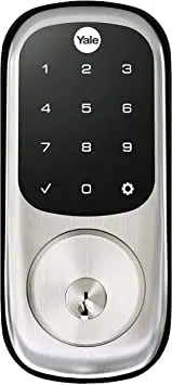
Yale Assure Lock
Touchscreen Deadbolt
Installation and Programming Instructions
(YRD226/YRD426)
®
x3
#8-32 x 5/16"
Machine screws
x4
#7 wood & #8-32
machine x 20mm
Combination screws
x2
M6x59.5mm
Long through bolt
FAILURE TO FOLLOW THESE INSTRUCTIONS COULD RESULT IN DAMAGE TO
THE PRODUCT AND VOID THE FACTORY WARRANTY
Optional
Network Module
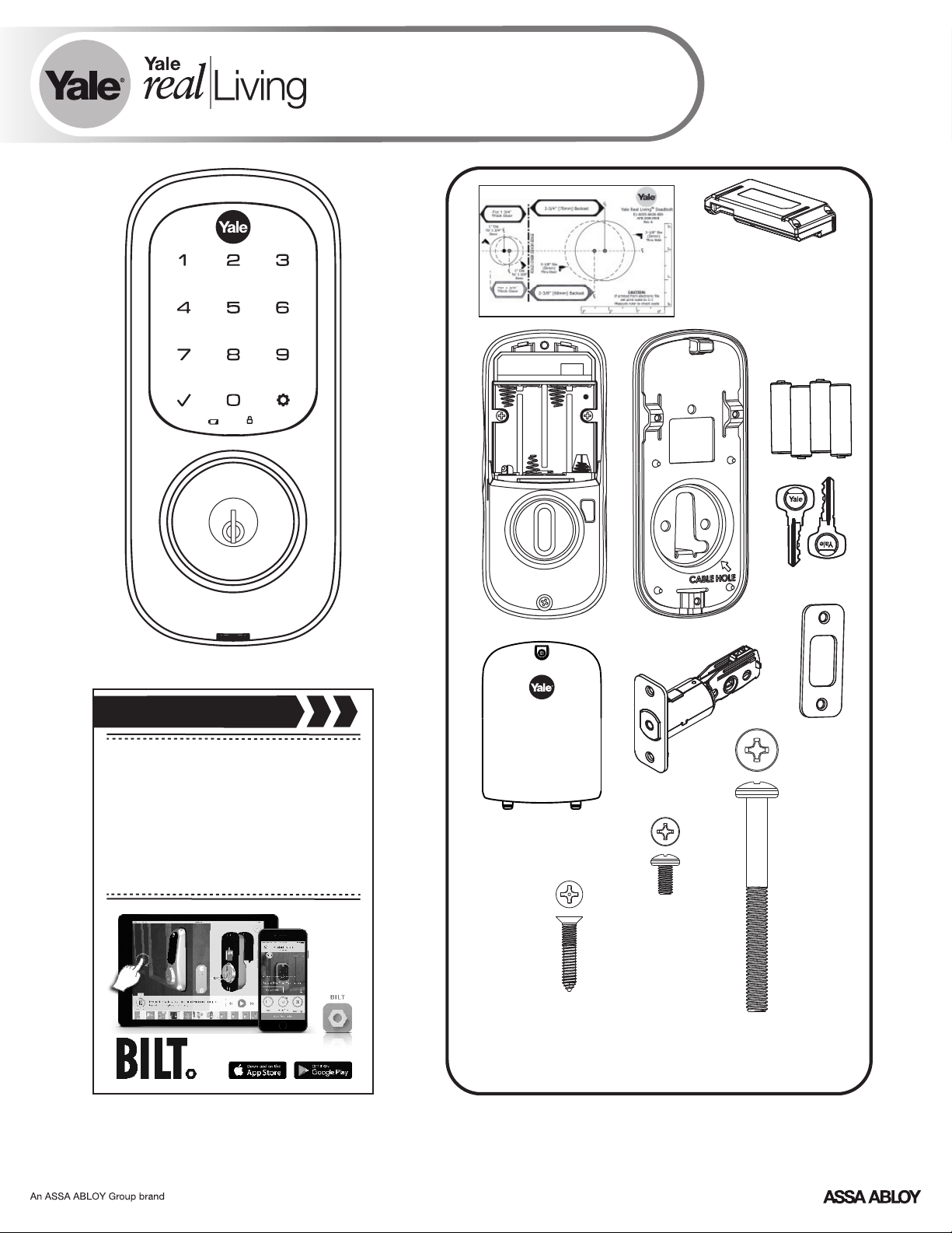
Before you begin
for step-by-step installation
instructions & to register
your product
DOWNLOAD
THE BILT APP
P/N YRL-TSINSTL-FUL Rev G
2
Preparing Door
P/N YRL-TSINSTL-FUL Rev G
3
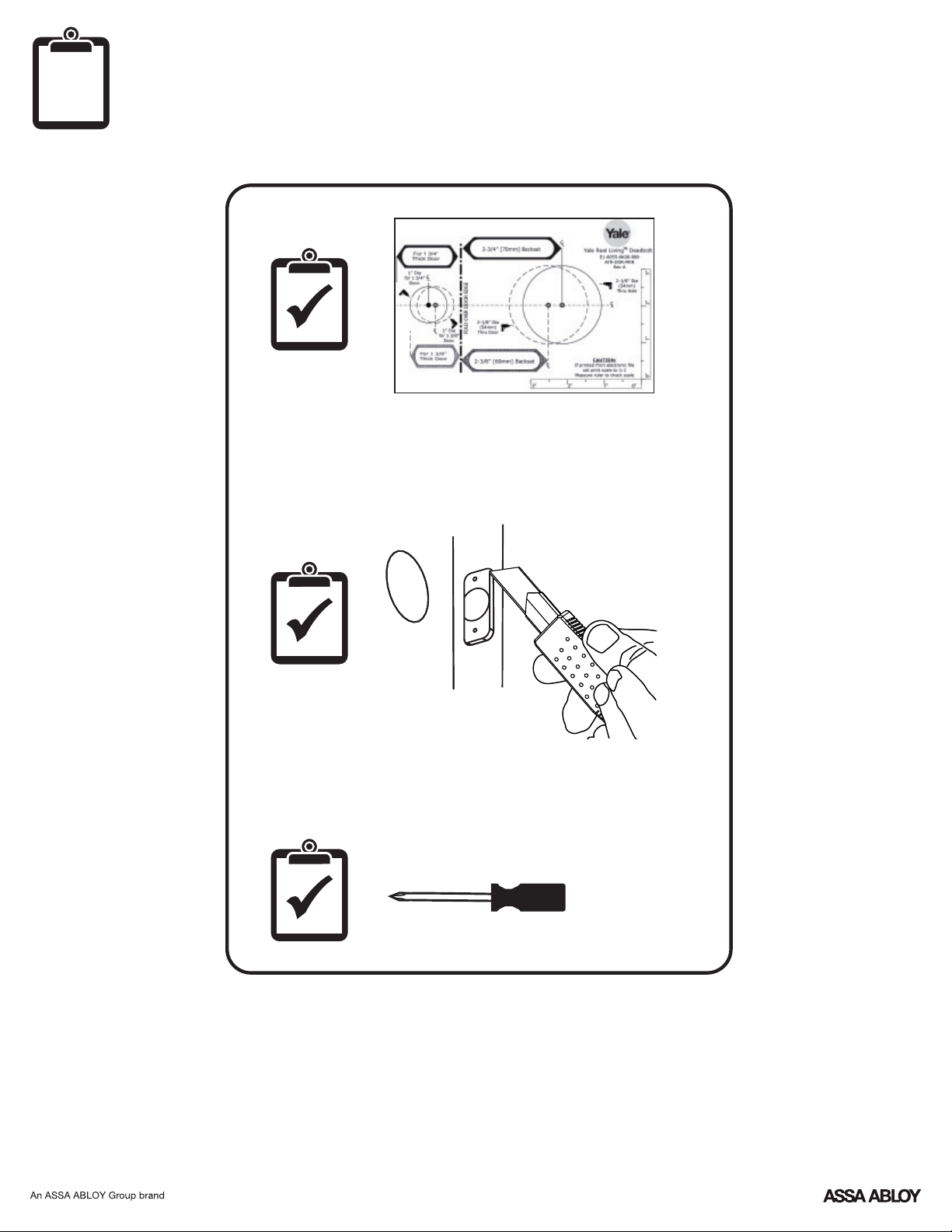
Optional Fire Kit Parts
For Model YRD620 ONLY
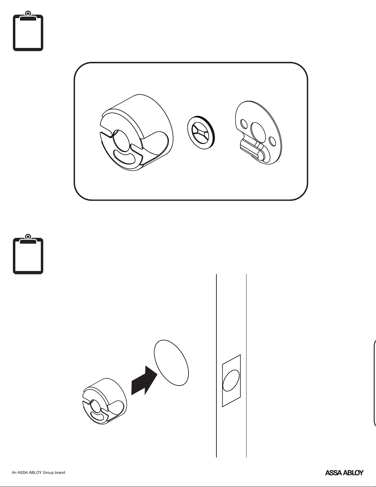
Installing Optional Fire Cup
Inside of Door
O
optional
O
optional
P/N YRL-TSINSTL-FUL Rev G
4
O
x4
1
defaut
2-3/8" position
2-3/4" position
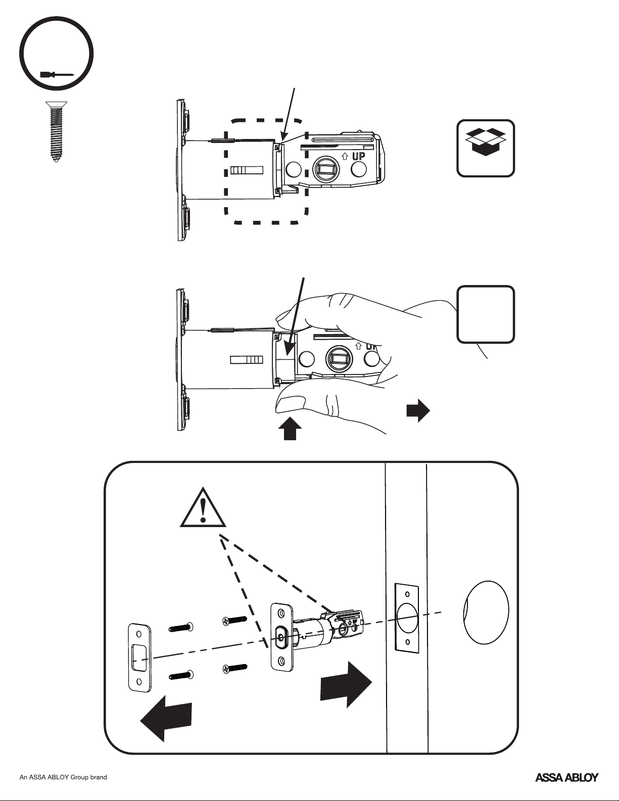
Installing Latch & Strike Plate
Press
Pull
optional
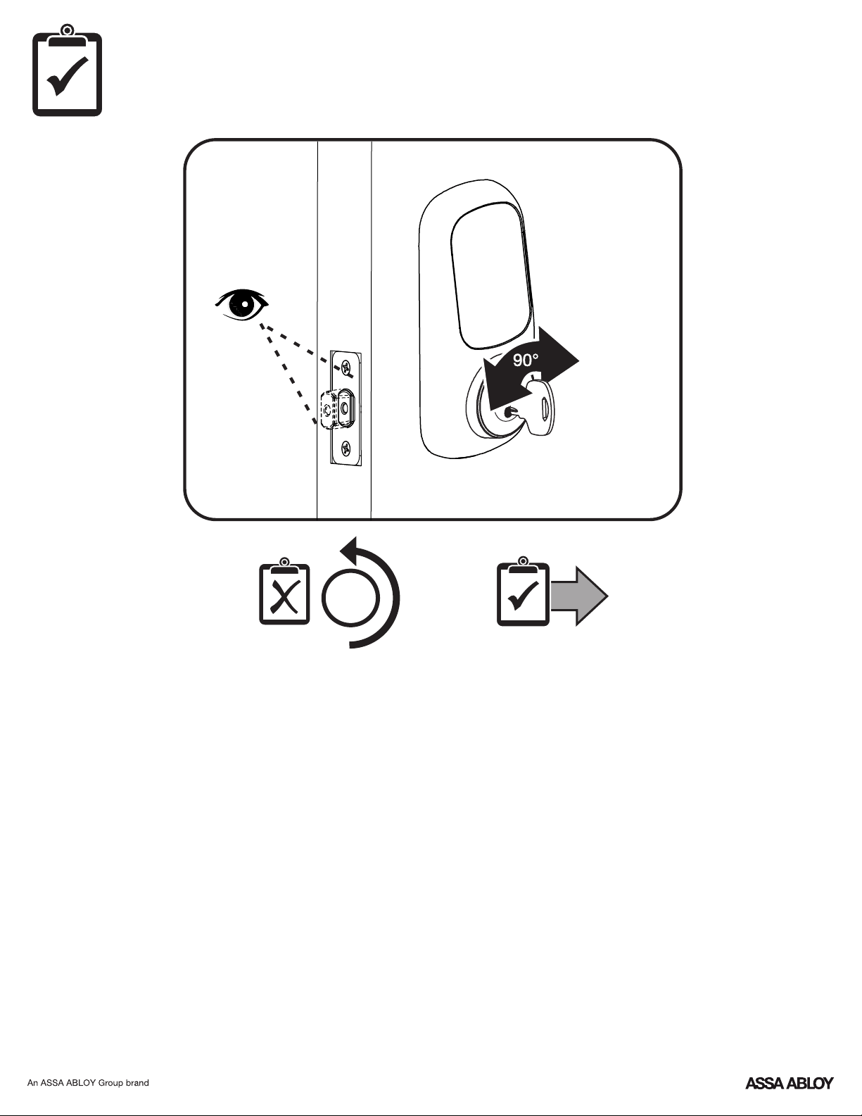
Bolt must be in retracted
(unlocked) position. Note
horizontal orientation of
mechanism.
P/N YRL-TSINSTL-FUL Rev G
5
2
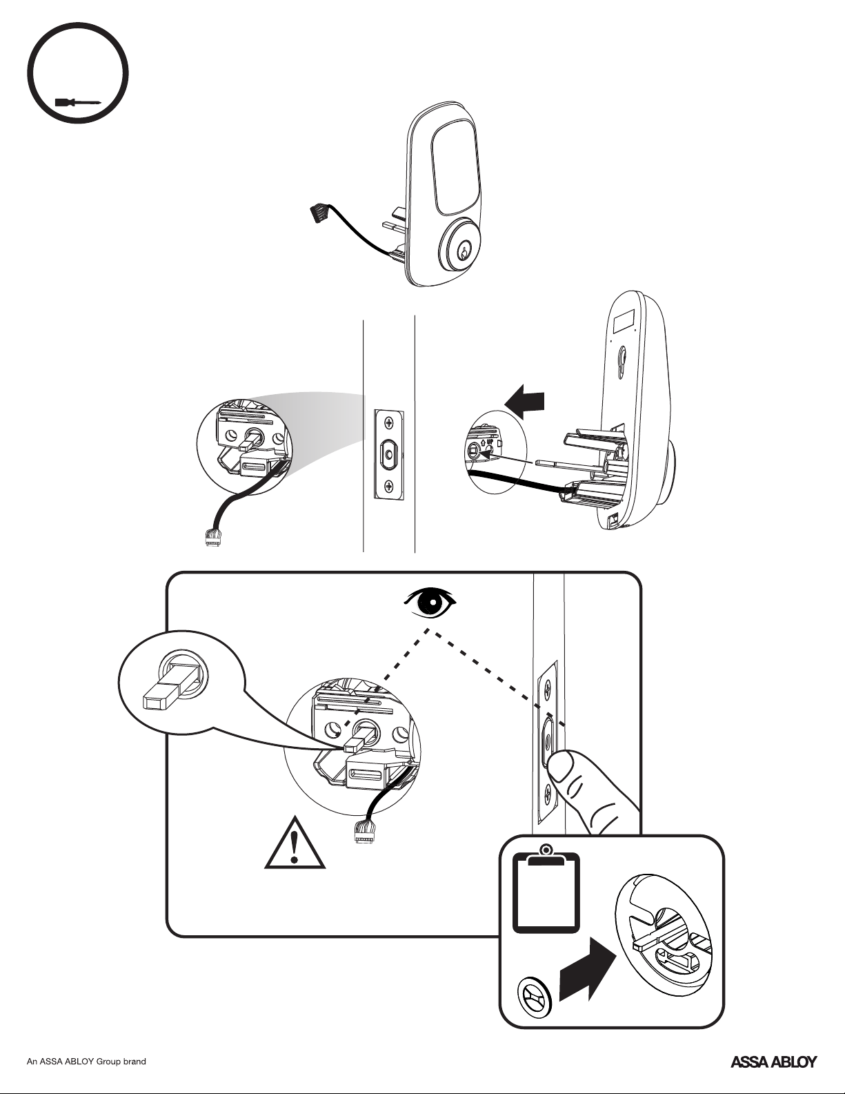
Installing Touchscreen Escutcheon
Outside of DoorInside of Door
Bolt must be in retracted (unlocked)
position. Note horizontal orientation
of mechanism.
O
optional
P/N YRL-TSINSTL-FUL Rev G
6
x2
3
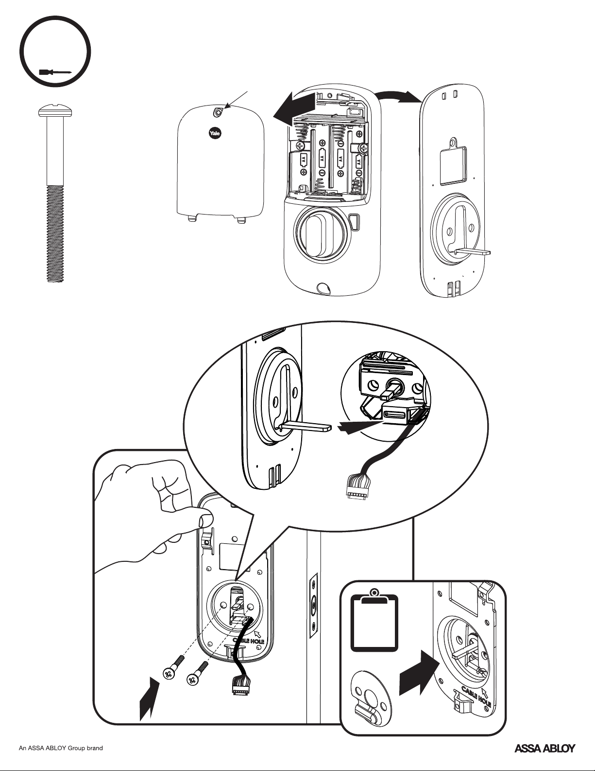
Installing Interior Mounting Plate
Loosen screw to
remove cover.
O
optional

4
Attaching the Cable Assembly
P/N YRL-TSINSTL-FUL Rev G
7

P/N YRL-TSINSTL-FUL Rev G
8
x3
5
Installing Interior Escutcheon
3
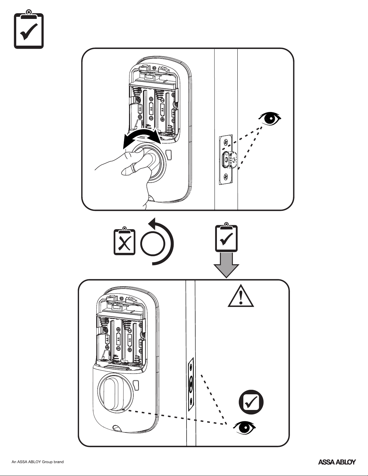
Testing Operation
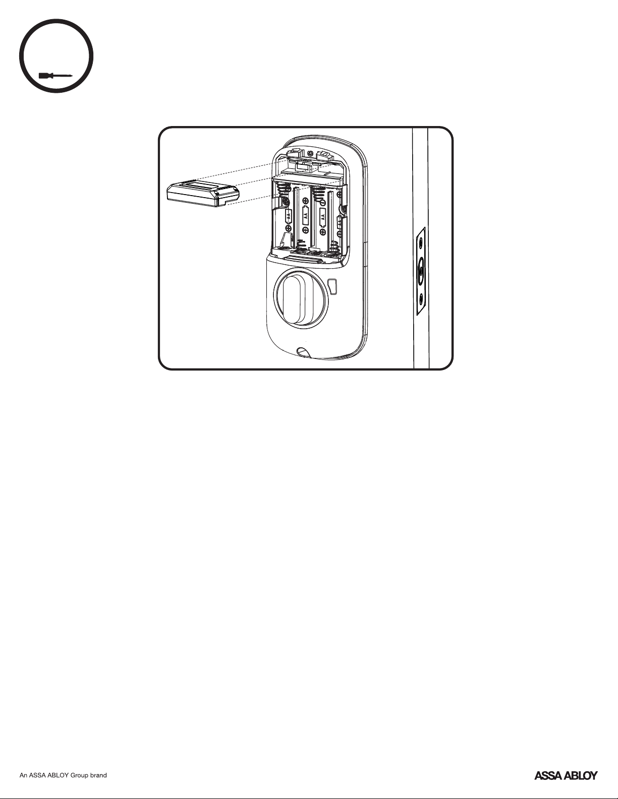
Bolt must be in retracted
(unlocked) position before
installing batteries.
P/N YRL-TSINSTL-FUL Rev G
9
P/N YRL-TSINSTL-FUL Rev G
10
2
Testing Operation
P/N YRL-TSINSTL-FUL Rev G
11
6
Installing Optional Network Module
P/N YRL-TSINSTL-FUL Rev G
12
7
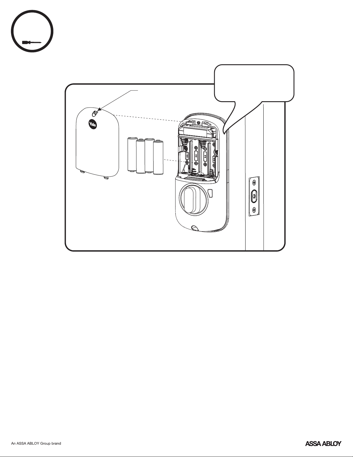
Installing Batteries & Cover
Continue with Programming Instructions to customize your product.
® ®
Congratulations, you've installed the Yale Assure Lock
Touchscreen Deadbolt (YRD226/YRD426)!
Tighten screw
to replace cover.
"Welcome to
Yale Real Living."
Programming Instructions
OR
Master PIN Code must be created before any further programming.
Max User Codes = 250 with Z-Wave Plus or ZigBee network module
Max User Codes = 25 without network module or with iM1 network module
Nax User Codes = 12 with Bluetooth
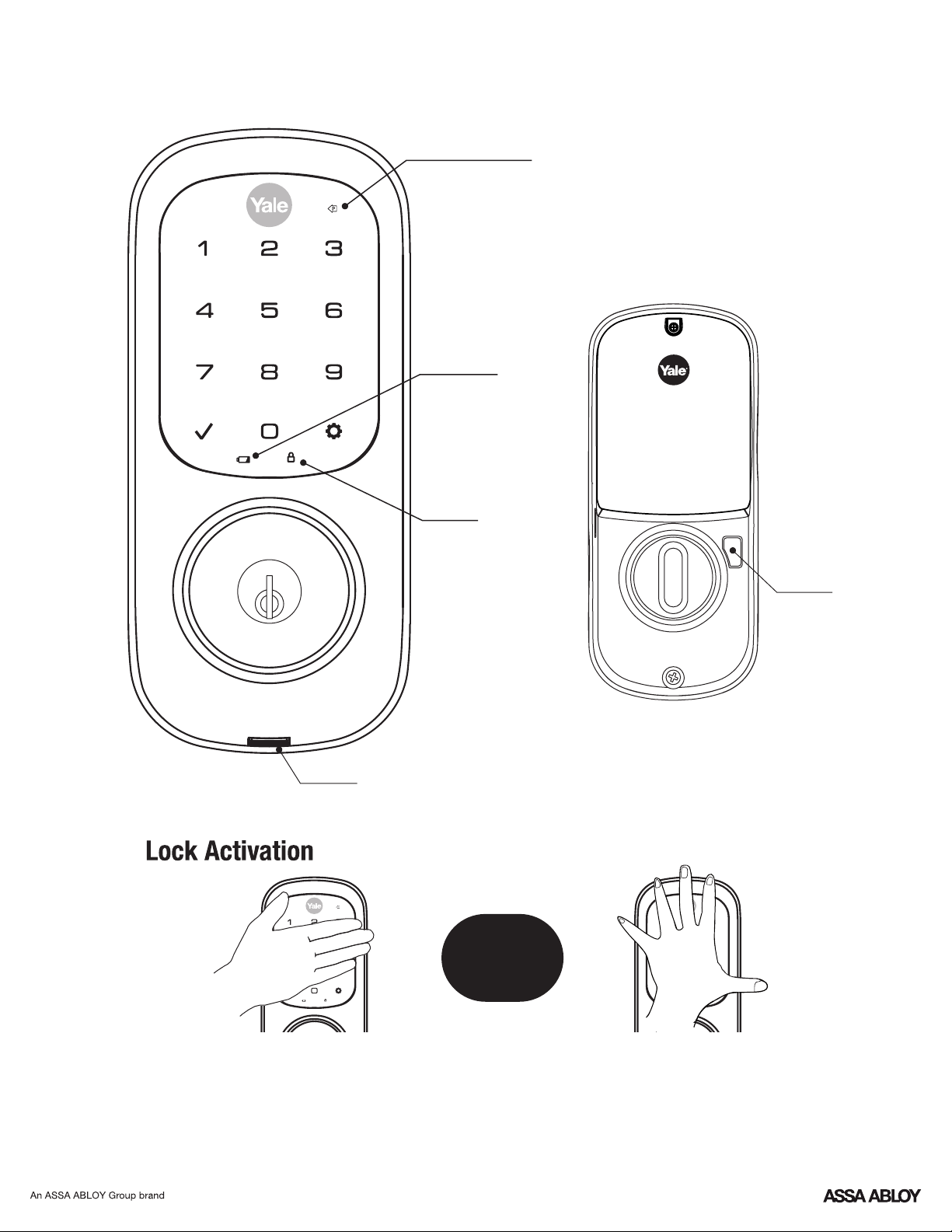
Interior Escutcheon
Privacy
Mode
Button
Speaker
"P" Key
(Return to Previous)
Low Battery
Indicator
Lockout
Mode
Exterior Escutcheon
P/N YRL-TSINSTL-FUL Rev G
13
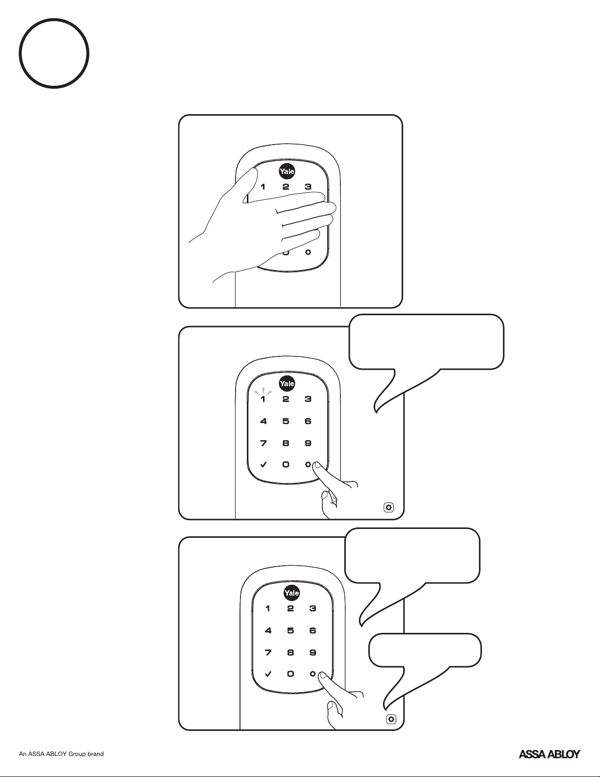
1
Creating a Master PIN Code must be performed upon installation or after resetting
the lock to factory default. Programming and use of lock is not possible until this
step has been successfully completed.
"Register Master
Code. Press the gear
key to continue."
"Enter a 4 to 8 digit
PIN code followed by
the gear key."
"Registered."
Enter 4-8
digit Master
PIN Code.
Press
Press
Creating Master PIN Code
P/N YRL-TSINSTL-FUL Rev G
14
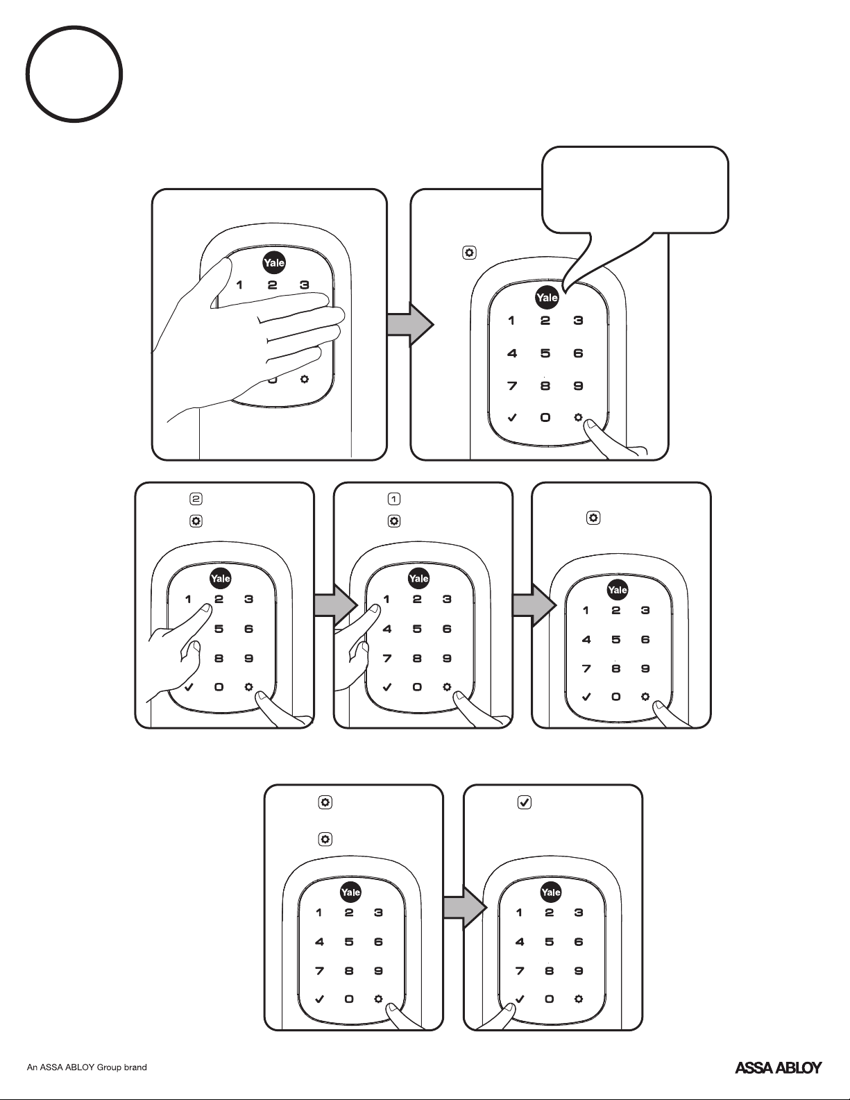
2
Creating User PIN Codes
Master PIN code must be created first.
*Max user codes = 250 with Z-Wave Plus or ZigBee network module
Max user codes = 25 without network module or with iM1 network module
Max user codes = 12 with Bluetooth
"Menu Mode,
enter number,
press the gear key
to continue."
Enter Master
PIN code
Press
Press
Press
Press
Press
Press
Enter 4-8 digit PIN code
Press
Enter 4-8 digit PIN code
Press
(code flashes)
Adding more *User Codes:
To end programming:
Press
P/N YRL-TSINSTL-FUL Rev G
15
P/N YRL-TSINSTL-FUL Rev G
16
3
PIN Code Management (With Network Module - Up to 250 Users)
Master
User ___
User ___
User ___
User ___
User ___
User ___
User ___
User ___
User ___
User ___
User ___
User ___
User ___
User ___
User ___
Enter PIN Code
Press
Code Chart
Duplicate if necessary
User Name
User Type
PIN Code
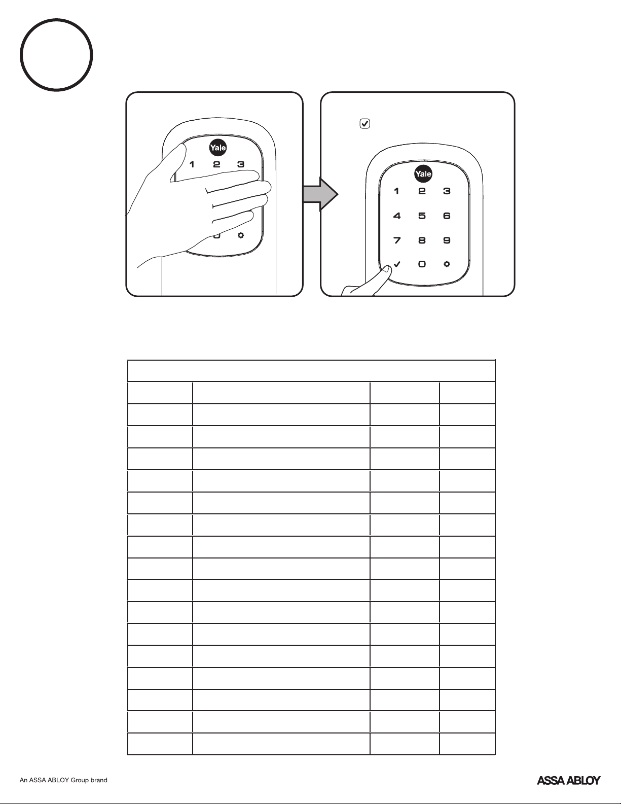
Unlocking Door with PIN Code
User #
P/N YRL-TSINSTL-FUL Rev G
17
Interior Escutcheon
Resetting Lock to Factory Default
Reset
Button
5. Replace battery cover.
When lock is reset to factory defaults all user codes (including the
Master PIN code*) are deleted and all programming features are reset
to original default settings (see below).
3. The reset button (see image at right) is located beside the PCB
cable connector.
4. While pressing the reset button (minimum of 3 seconds) reinstall
batteries. Release reset button.
Upon reset, Master PIN Code creation is the only option available and
must be performed prior to any other programming of the lock.
1. Remove the battery cover and batteries.
2. Remove the interior escutcheon to access the reset button.
P/N YRL-TSINSTL-FUL Rev G
18
Factory Settings
*The Master PIN code must be registered prior to any other programming of the lock.
Registration required*
Settings
Factory Setting
Master PIN Code
Automatic Re-lock
Disabled
Lockout Mode
Disabled
Language Setting
English
Wrong Code Entry Limit
5 Times
Shutdown Time 60 Seconds
Volume Setting
Enabled (Low)
Privacy Setting
Disabled
One Touch Locking
Enabled
Inside Indicator Light
Disabled (Off)
Automatic Re-lock Time
30 Seconds
Escape Return Mode (Model YRD620 only)
Disabled

P/N YRL-TSINSTL-FUL Rev G
19
Definitions
Shutdown Time: The unit will shutdown (flashing RED) for sixty (60) seconds and not allow operation after the
wrong code entry limit (5 attempts) has been met.
ZigBee network module is 250; without network module or with iM1 network module, maximum is 25; with
Bluetooth, maximum is 12. Note: When deleting user pin code(s), screen will display user pin code being deleted.
User PIN Code: The user code operates the lock. The maximum number of user codes with Z-Wave Plus or
Volume Setting Mode: The volume setting for PIN code verification is set to Low (2) by default; otherwise it can
be set to High (1) or Silent (3) for quiet areas.
Privacy Mode: Privacy mode is disabled by default. Enable Privacy Mode by pressing the privacy button for 4
seconds to put the lock in do-not-disturb mode (all pin codes are disabled).
Tamper Alert: Audible alarm sounds if attempting to forcibly remove outside lock from door.
Wrong Code Entry Limit: After five (5) unsuccessful attempts at entering a valid PIN code, the unit will shut
down and not allow operation for sixty (60) seconds.
One Touch Locking: When the latch is retracted, activating the keypad will extend the latch (during Automatic
Re-lock duration or when Automatic Re-lock is disabled). When One-Touch Re-lock is not in use (disabled), any
valid PIN code will re-lock the lock.
Previous: While in Menu Mode, pressing this icon cancels the current operation and returns the user to the
previous step.
All Code Lockout Mode: This feature is enabled by the Master code. When enabled, it restricts all user (except
Master) PIN code access. When attempting to enter a code while the unit is in Lockout, the RED locked padlock
will appear on the screen.
Network Module Setting: With the optional Network Module installed, this setting becomes available thru the
Main Menu (7) and allows the lock to connect with a network controller.
Language Setting Mode: Choosing English (1), Spanish (2) or French (3) becomes the (default) setting for the
lock's voice prompts.
Master PIN Code: The Master PIN code is used for programming and for feature settings. It must be created
prior to programming the lock. The Master code will also operate (unlock/lock) the lock.
Automatic Re-lock Time: After a successful code entry or manual unlock with the key, the lock will automatically
re-lock after each unlock in an effort to keep your home secure. This feature is optional, and can be turned off. In
the ON mode, the lock will automatically re-lock after thirty (30) seconds.
Low Battery: When battery power is low, the Low Battery Warning indicator flashes RED. If battery power is
completely lost, use the cylinder key override.
Inside Indicator Light: Located on the interior escutcheon. Shows active status (Locked) of lock and can be
enabled or disabled in the Advanced Lock Settings (Main Menu selection #3).
P/N YRL-TSINSTL-FUL Rev G
20
*The Master PIN code must be registered prior to any other programming of the lock.
Follow the voice commands.
Lock Response: "Menu mode, enter number, press key to continue."
2. Enter 4-8 digit master PIN code* followed by key.
3. Enter digit corresponding to the function to be performed followed by the key.
1. Touch screen with back of hand or palm to activate.
M
U
**This function appears only with
network module installed.
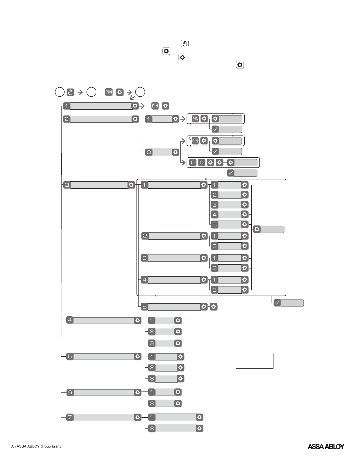
Default settings
in bold.
Master PIN Code Setting
User PIN Code Registration
Continue
Complete
Register
Delete
Continue
Complete
M
2
3
1
Join the Network
Enable
Disable
English
Spanish
French
Silent
Low
High
Complete
Exit the Network
Volume Setting
Language Setting Mode
Lockout Mode
**Network Module Setting
Privacy Setting Mode
Enable
Disable
Handing the Lock
Preforms automatic
handing of the lock
Advanced Lock Settings
Automatic Re-lock
Disable
30 sec
Inside Indicator Light
One Touch Locking
Enable
Disable
Enable
Disable
Continue
60 sec
3 min
2 min
Continue
Complete
Model YRD226 Feature Programming Through
Menu Mode Using Master PIN code*
P/N YRL-TSINSTL-FUL Rev G
21
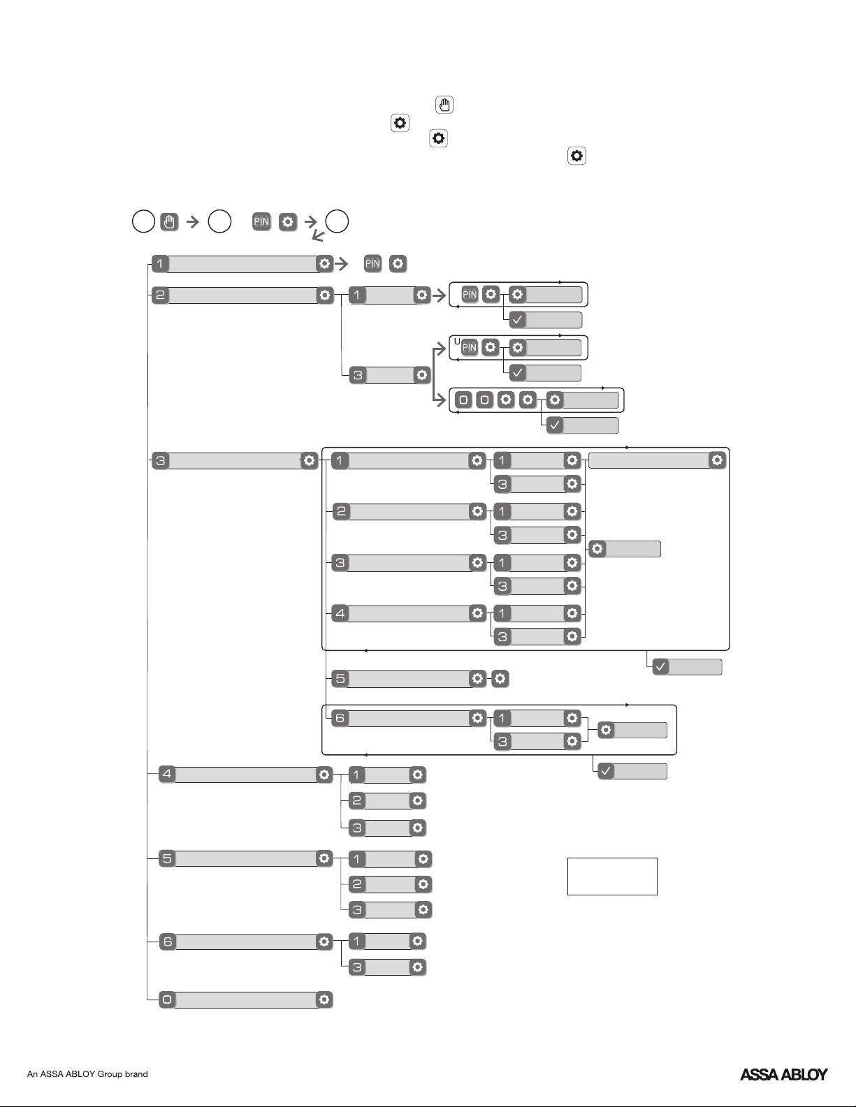
Model YRD620 Feature Programming Through
Menu Mode Using Master PIN code*
*The Master PIN code must be registered prior to any other programming of the lock.
1. Touch screen with back of hand or palm to activate.
2. Enter 4-8 digit master PIN code* followed by key.
Lock Response: "Menu mode, enter number, press key to continue."
3. Enter digit corresponding to the function to be performed followed by the key.
Follow the voice commands.
M
U
Master PIN Code Setting
User PIN Code Registration
Continue
Complete
Register
Delete
Continue
Complete
M
2
3
1
Continue
Complete
Default settings
in bold.
*If Escape Return Mode is enabled,
Automatic Re-lock cannot be enabled.
Language Setting Mode
Set Up SEOS Card
Advanced Lock Settings
Enable
Disable
English
Spanish
French
Silent
Low
High
Complete
Volume Setting
Lockout Mode
Privacy Setting Mode
Enable
Disable
Handing the Lock
Preforms automatic
handing of the lock
*Automatic Re-lock
Inside Indicator Light
One Touch Locking
Enable
Disable
Enable
Disable
Continue
Enable
Disable
*Escape Return Mode
Enable
Disable
Enter Time 1-180 Sec
Continue
Complete
P/N YRL-TSINSTL-FUL Rev G
22
PIN codes must consist of 4 to 8 digits to register.
Disable Auto Re-lock Mode to lock the door (automatically).
The digits entered were incorrect or incomplete. Re-enter
the correct code followed by the check key.
This is the alert to replace the batteries. Replace all four
(4) batteries* with new AA Alkaline batteries.
Check to see if Silent Mode is enabled (see Feature #4).
Setting/managing Lockout Mode is done through
Master Code only. Contact the Master user.
Check to see if the lock is set to Lockout Mode.
Contact the Master user.
Only the Master can enable/disable Lockout Mode.
Lockout Mode is enabled.
Check or gear cannot be used as part of the PIN code.
Contact the Master user.
Check that the wire harness is firmly connected to the PCB.
Check the door gaps for any foreign objects between door
and frame.
Batteries may be completely discharged.
Check batteries are installed and oriented correctly (polarity)
in the battery case.
User codes must be entered within 5 seconds (while
touchscreen is active) or process will have to be restarted.
Registration/management of PIN codes is set by the
authority of the Master Code, which is set first.
The same PIN code cannot be used for multiple users.
If low battery indicator is lit (see below), change batteries*.
Check to see if Auto Re-lock Mode is enabled.
Batteries do not have enough power. Replace batteries*.
Use mechanical key to gain entry and replace batteries*.
Check to see if touchscreen harness is fully connected
and not pinched.
Check batteries are in good condition; replace batteries*
if discharged.
If touchscreen numbers are visible, check to see if they
respond when pressed.
Touchscreen becomes active when pressed w/whole hand.
Use a larger area of the hand or fingers and verify contact
with at least 3 areas.
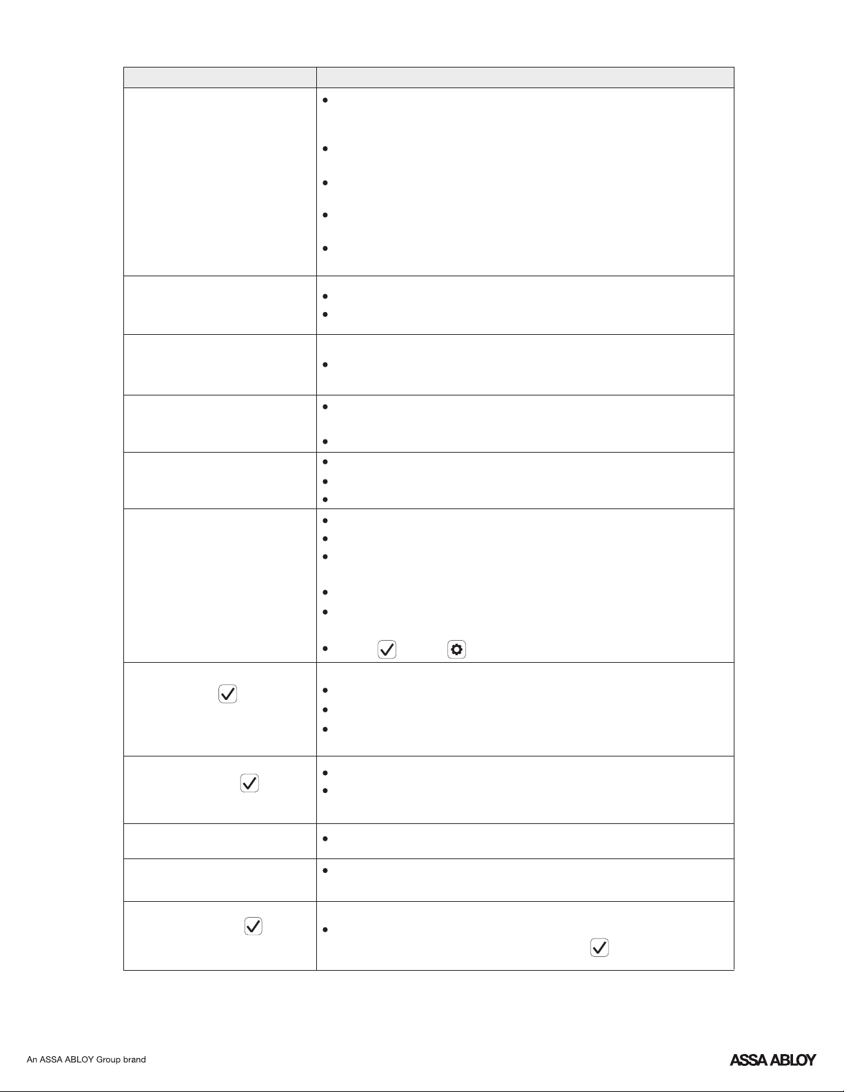
Symptom
Suggested Action
Lock does not respond –
door is open and
accessible.
Unit chimes to indicate
code acceptance, but the
door will not open.
Unit operates to allow
access, but will not
automatically re-lock.
PIN codes will not register.
Upon entering a PIN code
and pressing key, the
unit displays "invalid code"
error or lock times out with-
out responding.
Upon entering a PIN code
and pressing the key,
the red padlock icon appears
and there are different tones.
The unit operates, but it
makes no sound.
The unit responds
"Low Battery"
Upon entering a PIN code
and pressing the key,
the unit responds "Wrong
number of digits".
Lock does not respond –
door is locked and
inaccessible.
Unit is on for a while then
shows no reaction. Lights
dim.
* When batteries are replaced, Network Module locks have a real time clock that will be set through the User Interface (UI);
it is recommended to verify correct date and time particularly those locks operating under Daylight Saving Time (DST).
** Network Module locks only
Programming Troubleshooting
P/N YRL-TSINSTL-FUL Rev G
23
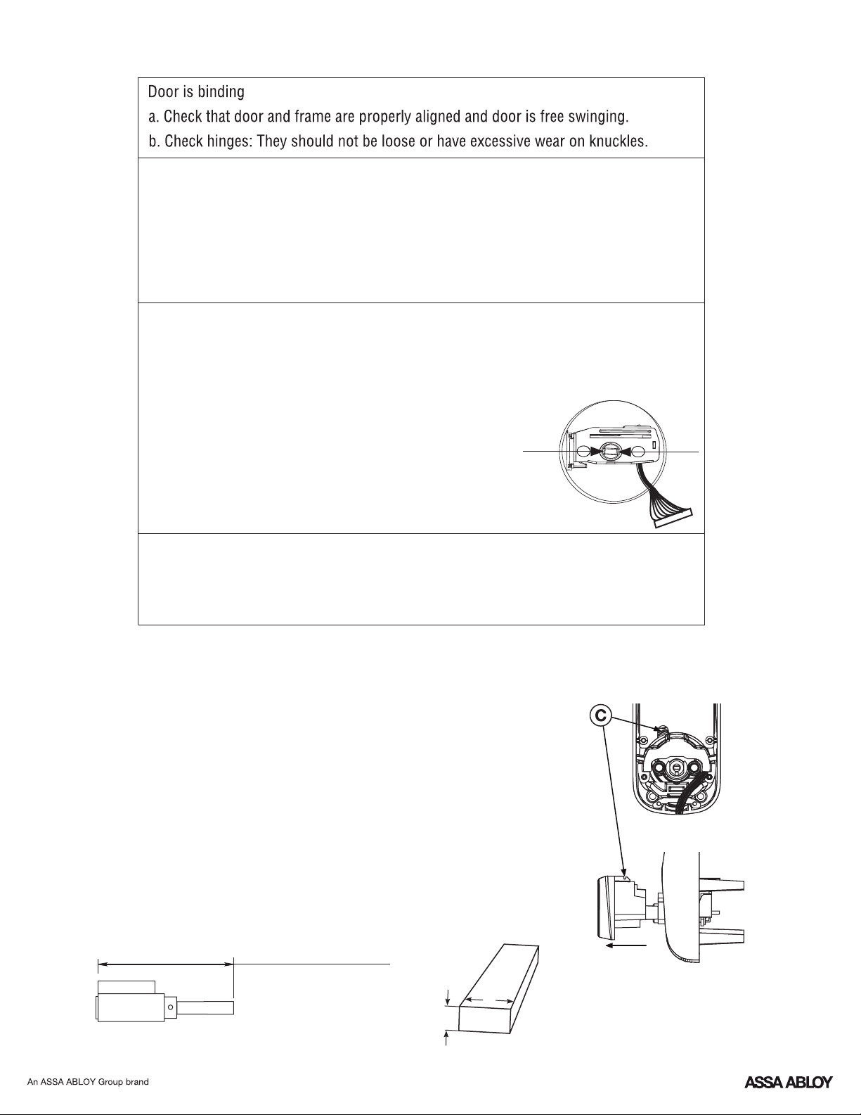
L
w
T
Changing Lock: Replacing Cylinder
Hardware Troubleshooting
Cycle lock in both the locked and unlocked positions. If problems are found:
1-3/8"* - 2" thick doors:
L = 3-1/2" (88.8mm)
2" - 2-1/4" thick doors:
L = 3-3/4" (95.3mm)
W = .2" (5.2mm)
Tailpiece
T = .098" (2.5mm)
Before installing cylinder, be sure tailpiece is correct length (see
below).
2. To install new cylinder:
1. To Remove cylinder:
D. Remove cylinder by pulling outward towards outside of door.
C. Insert small flathead screwdriver under spring. Gently lift spring.
Note: Notch on top of cylinder engages spring.
A. Remove outside escutcheon from door.
B. Remove rubber gasket.
A. Reverse previous steps for removing cylinder.
*Requires addition of Thin Door Kit.
Bolt will not deadlock
a. Check for sufficient clearance of the bolt within the strike-side jamb. Correct this by
increasing the depth of the pocket for the bolt.
b. Check for misalignment of bolt and/or strike which may be preventing bolt from
properly entering the strike. With the door open, extend and retract the bolt; if it is
smooth, check the strike alignment.
Bolt does not extend or retract smoothly
a. Bolt and strike are misaligned, see above.
b. Check the backset of door relative to adjustments already made to bolt.
c. Verify proper door preparation and re-bore holes that are too small or misaligned.
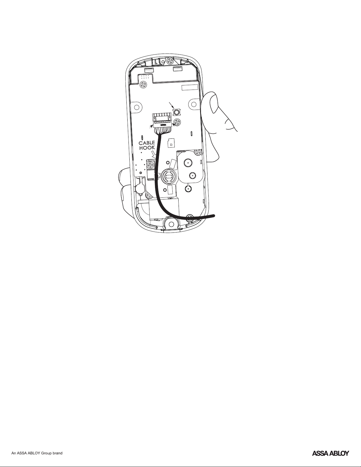
d. Verify keypad wire harness is routed under the bolt (see Fig. A).
e. Verify bolt is installed with correct side up (Fig. A).
Keypad numerics are scrolling
Remove interior escutcheon and check to ensure that the wire harness lies flat against
the back recessed area and is properly routed along the side of the escutcheon and
tucked under the plastic cable guide.
Figure A

P/N YRL-TSINSTL-FUL Rev G
24
Class B Equipment
• Increase the separation between the equipment and receiver.
Industry Canada:
This equipment has been tested and found to comply with the limits for a Class B digital device, pursuant to Part 15 of the FCC
Rules. These limits are designed to provide reasonable protection against harmful interference in a residential installation. This
equipment generates, uses, and can radiate radio frequency energy and, if not installed and used in accordance with the
instructions, may cause harmful interference to radio communications. However, there is no guarantee that interference will not
occur in a particular installation. If this equipment does cause harmful Interference to radio or television reception, which can be
determined by turning the equipment off and on, the user is encouraged to try to correct the interference by one or more of the
following measures:
• Connect the equipment into an outlet on a circuit different from that to which the receiver is connected.
Cet appareillage numérique de la classe A répond à toutes les exigences de l'interférence canadienne causant des règlements
d'équipement.
FCC:
This Class A digital apparatus meets all requirements of the Canadian Interference Causing Equipment Regulations.
• Consult the dealer or an experienced radio/TV technician for help.
• Reorient or relocate the receiving antenna.
Warning: Changes or modifications to this device, not expressly approved by Yale Security Inc. could void the user's authority
to operate the equipment.
Product Support Tel 1-855-213-5841 • www.yalehome.com
Yale®, Yale Real Living® and Assure Lock® are registered trademarks of ASSA ABLOY Residential Group. Other
products' brand names may be trademarks or registered trademarks of their respective owners and are mentioned for
reference purposes only. © Copyright 2019. All rights reserved. Reproduction in whole or in part without the express
written permission of ASSA ABLOY Residential Group is prohibited.