Loading ...
Loading ...
Loading ...
11
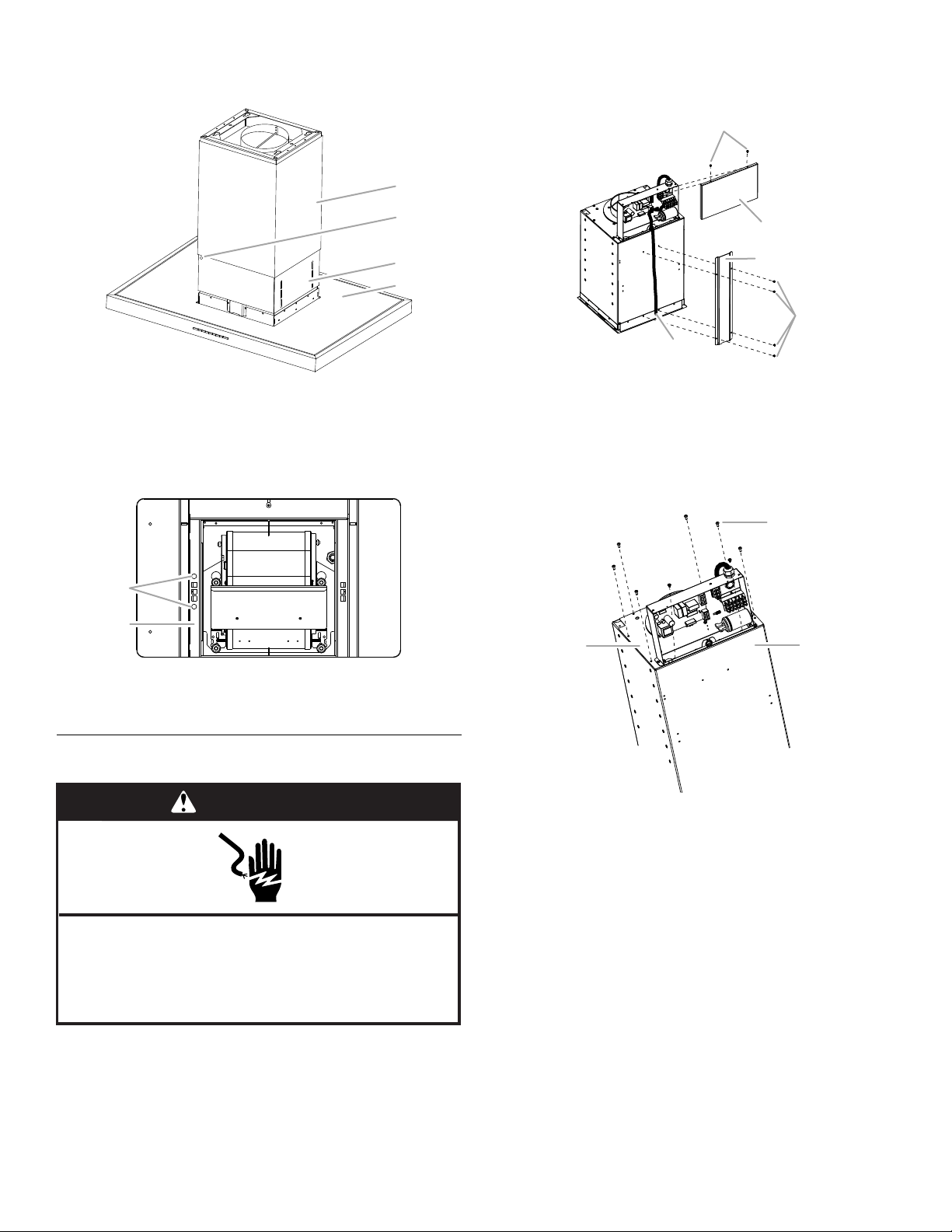
9. Push up and hold the lower chimney cover, and remove the
(2) 4 x 13 mm screws. Slide the lower chimney cover down
onto the top of the range hood canopy.
10. Replace (2) 4 x 13 mm service screws into storage area
inside range hood blower housing.
11. Go to “Complete Installation” section.
Make Electrical Connection
1. Disconnect power.
2. Remove the (2) screws from the top of the electrical box
cover and set the screws and cover aside.
3. Using a T20
®
Torx
®
driver, remove the (4) screws from the wire
protector race panel and set the part and screws aside.
Do not damage the wiring.
4. Using a T20
®
Torx
®
driver, remove the (2) screws inside the
electrical box holding the module plate and the (6) other
screws around the perimeter of the module plate.
A. Lower chimney cover
B. 4 x 13 mm screw (2)
C. Upper chimney cover
D. Range hood canopy assembly
A. 4 x 13 mm service screws (2)
B. Inside area of range hood blower housing
C
A
D
B
A
B
WARNING
Electrical Shock Hazard
Disconnect power before servicing.
Replace all parts and panels before operating.
Failure to do so can result in death or electrical shock.
A. Electrical box cover
B. Screws - electrical box cover (2)
C. Wire protector race
D. Screws - wire protector race (4)
E. Electrical wiring
A. Screws - module top assembly (8)
B. Module plate assembly
C. Range hood module
A
B
C
D
E
A
B
C
Loading ...
Loading ...
Loading ...