Loading ...
Loading ...
Loading ...
subzero.com
|
9
INSTALLATION
DOOR ADJUSTMENT
The doors of side-by-side and over-and-under models can
be adjusted in and out, and side to side tilt. The doors of
side-by-side models can also be adjusted up and down.
To make adjustments, slightly loosening the two upper hinge
bolts on the upper hinge plate using a
1
/2" wrench. Refer to
the illustration below.
In and out adjustment | For a left-hinge door, using a
5
/32" allen wrench, turn the adjustment bolt clockwise to
bring the handle side of the door inward, and counterclock-
wise to move the handle side outward. Reverse directions
for a right-hinge door.
Side to side tilt adjustment | For a left-hinge door, using a
3
/8" wrench, turn the adjustment bolt clockwise to raise the
handle side of the door, and counterclockwise to lower the
handle side. Reverse directions for a right-hinge door.
Up and down adjustment | For a left-hinge door, using a
1
/4" allen wrench, turn the adjustment bolt clockwise to raise
the door and counterclockwise to lower. Refer to the illustra-
tion below. Reverse directions for a right-hinge door.
Alignment
LEVELING
Once the unit is in position, turn the front leveling legs
clockwise to adjust the height. The rear height adjustment
can be made from the front of the roller base. Using a
3
/8"
socket, turn the
3
/8" hex bolt clockwise to raise the unit or
counterclockwise to lower. Use the lowest torque setting
when using a power drill. Do not turn the rear leveling legs
by hand. Refer to the illustration below.
When the unit is properly leveled, door and drawer adjust-
ments are less likely to be necessary.
IMPORTANT NOTE: Level the unit to the oor, not sur-
rounding cabinetry. This could affect the operation of the
unit, such as door closing.
WARNING
To reduce the possibility of the unit tipping forward, the
front leveling legs must be in contact with the floor.
FRONT
LEVELING LEG
REAR
ADJUSTMENT
Rear roller base adjustment.
UPPER
HINGE BOLTS
SIDE TO SIDE
TILT ADJUSTMENT
IN AND OUT
ADJUSTMENT
Door adjustment bolts.
Up and down door adjustment.
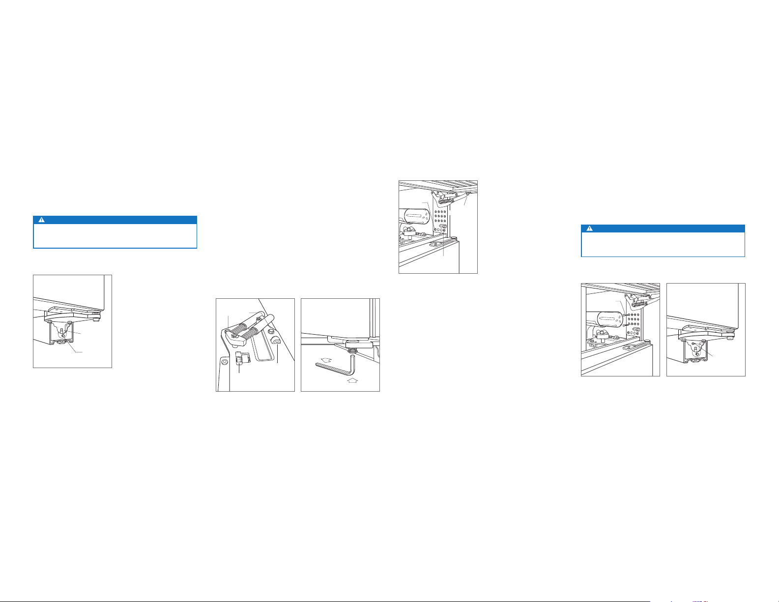
ANCHORING
After the unit has been leveled and door adjustment com-
pleted, anchor the unit to the opening to ensure a proper t
and secure installation.
To anchor the top of the unit, open the grille and install the
screws provided, through the grille frame into cabinetry.
There are several hole locations. Refer to the illustration
below. Check for proper door clearance by opening the
door.
To anchor the bottom of the unit, drive a screw through the
side hole inside each roller base assembly. The screw will
need to go in at an angle to attach properly. Refer to the
illustration below. Additional material may be needed behind
the cleat to ensure sufcient anchoring.
CAUTION
If the screws provided are not suitable for the installa-
tion, use adequate screws.
ANCHORING
SCREWS
ANCHORING
SCREW
Top anchoring.
Bottom anchoring.
Completion
GRILLE INSTALLATION
Install the grille assembly and check for proper t. The grille
is designed to rest on the upper door hinge(s) to minimize
the reveal between the top of the door and bottom of the
grille. To eliminate interference, the grille height can be
adjusted. Loosen the four grille adjustment screws (two on
each side) and adjust the grille height as needed. Refer to
the illustration below.
BACK GRILLE
SCREW
FRONT
GRILLE SCREW
GRILLE
ADJUSTMENT
SCREW
Grille height adjustment.
Loading ...
Loading ...
Loading ...