30”
Install the
outlet box
on either
side of the C
L
36
1
4” ±
1
4”
1
1
8”
47
1
2”
26
7
8”
w/o handle
29
1
2”
with handle
30”
36
1
4” ±
1
4”
1
1
8”
43
7
8”
26
7
8
”
w/o handle
29
1
2”
with handle
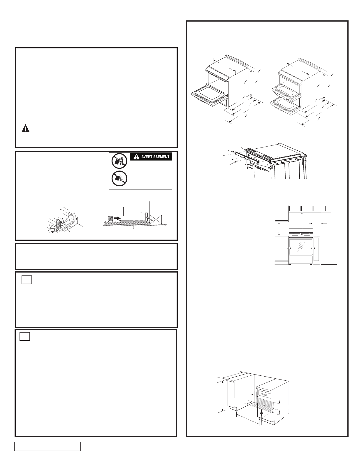
NOTE:
Use a 4’ power cord to prevent interference with the storage
drawer. Power cords 4½’ to 6’ long may have to be dressed to allow for
proper drawer closing.
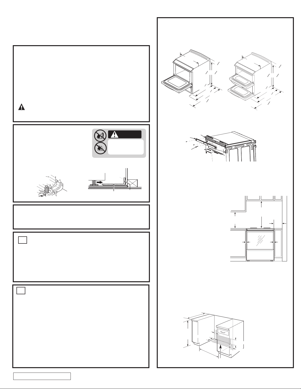
MINIMUM DIMENSIONS BETWEEN COOKTOP, WALLS AND ABOVE
THE COOKTOP:
A. The range must be placed with
1/2” minimum clearance at the
back wall and side walls of the
cabinet. Make sure the wall cove-
ring, countertop, flooring and
cabinets around the range can
withstand the heat (up to 93.3°C/
200°F) generated by the range.
B. Allow 30” minimum clearance
between surface units and bottom
of unprotected wood or metal
cabinet, or allow a 24” minimum
when bottom of wood or metal
cabinet is protected by no less
than 1/4” thick flame retardant
millboard covered with not less
than No.28 MSG sheet metal, (.015”), .015” thick stainless steel, .024”
aluminum or .020” copper.
C.
To reduce the risk of burns or fire when reaching over hot surface elements,
cabinet storage space above the cooktop should be avoided. If cabinet
storage space is to be provided above the cooktop , the risk can be redu-
ced by installing a range hood that projects at least 5” beyond the front of
the cabinets. Cabinets installed above the cooktop must be no deeper
than 13”
A 6” spacing to surfaces less than 15” above the cooktop is recommen-
ded to reduce exposure to steam, grease splatter and heat.
A
C
B
A
C
Both
Sides
25” (63.5 cm)
Orient electrical receptacle so the length
is parallel to the floor.
6.98 cm (2 3/4") -
13.65 cm (5.3/8")
11.27 cm
(4.44")
6.98 cm
(2-3/4")
To reduce the risk of burns or fire when reaching over hot surface elements,
cabinet storage space above the cooktop should be avoided. If cabinet
storage space is to be provided above the cooktop, the risk can be reduced
by installing a range hood that projects at least 12.7 cm (5") beyond the front
of the cabinets. Cabinets installed above the cooktop must be no deeper
than 33 cm (13").
295D3314P001 REV.2 Pub. No. 29-6178
PREPARE THE OPENING (FOR INDOOR USE ONLY)
2
If the countertop area is not flat, excess tension may be applied to the glass
cooktop causing breakage and voiding the warranty. Make sure the wall
covering, countertop, flooring and cabinets around the range can withstand
the heat (up to 93˚C [200˚F]) generated by the range.
A. Allow 76.2 cm (30") minimum clearance between surface units and bottom
of unprotected wood or metal cabinet, or allow a 61 cm (24"
) minimum
when bottom of wood or metal cabinet is protected by no less then 6.3 mm
(1/4") thick flame retardant millboard covered with no less than No. 28 MSG
sheet metal .38 mm (.015") thick, .38 mm (.015") thick stainless steel,
.63 mm (.025") aluminum or .5 mm (.020") copper.
B. A minimum 15.2 cm (6") spacing to surfaces less than 38.2 cm (15")
above the cooktop and adjacent cabinetry is recommended to reduce
exposure to steam, grease splatter and heat. Allow 6.3 mm (1/4")
minimum clearance at the back wall.
C. The thickness of the countertop has to be a maximum of 3 cm (1.18").
REMOVE PACKAGING MATERIALS
Failure to remove packaging materials could result in damage to the
appliance. Remove all packing parts from oven, racks, heating elements
and drawer. Also, remove protective film and labels on the door, cooktop
(do not remove side protection on glass cooktops) and backguard.
Do not remove protective channel from sides of glass cooktop, if applicable,
until later in installation.
NOTE: Cut the orange shipping ties from the power cord, being careful not
to damage the cord.
1
TOOLS YOU WILL NEED
Drill with 1/8" Bit
Safety Glasses
Adjustable Wrench
Level
Tape Measure
Pliers
1/4" Nut Driver
NOTE: Installation information for
reference only. See Installation
Instructions shipped with product for
complete details and before attempting
to install. Anti-tip bracket must be
attached to the floor or wall to hold
either right or left rear leg leveler. Make
sure leg leveler reengages the bracket
when range is moved for any reason.
WARNING
• All ranges can tip
• Injury to persons could result
• Install anti-tip bracket
packed with range
• See Installation Instructions
Adjacent Cabinet
Or Final Location
Of Range Side Panel
Wall
Floor-Wood
Bracket
Side
Rear
Leveling
Leg
Floor-Concrete
Attachment To Wall
Bracket
Wall
Plate
Screw Must
Enter Wood
Or Metal
BEFORE YOU BEGIN
Read these instructions completely and carefully.
•
IMPORTANT—Save these instructions for local inspector’s use.
•
IMPORTANT—Observe all governing codes and ordinances.
• Note to Installer – Be sure to leave these instructions with Consumer.
• Note to Consumer – Keep these instructions for future reference.
• Skill level – Installation of this appliance requires basic mechanical
skills and advanced electrical skills.
• Proper installation is the responsibility of the installer.
•
Product failure due to improper installation is not covered under warranty.
WARNING: This appliance must be properly
connected by means of the supplied cord and plug. If your kitchen does not
have a receptacle, you must have one installed by a licensed electrician.
Installation Instructions
30" Electric Slide-In Ranges
Questions? Call 1.800.661.1616 or visit www.GEAppliances.ca
91.1cm-92.7cm
(35-7/8"-36.5") from
floor to countertop
30 ¼” - 31”
(76.8 -78.7 cm)
Back of
Range
Rear Trim
Screws
For all installations, install the required rear trim to back of range with 4 screws provided.
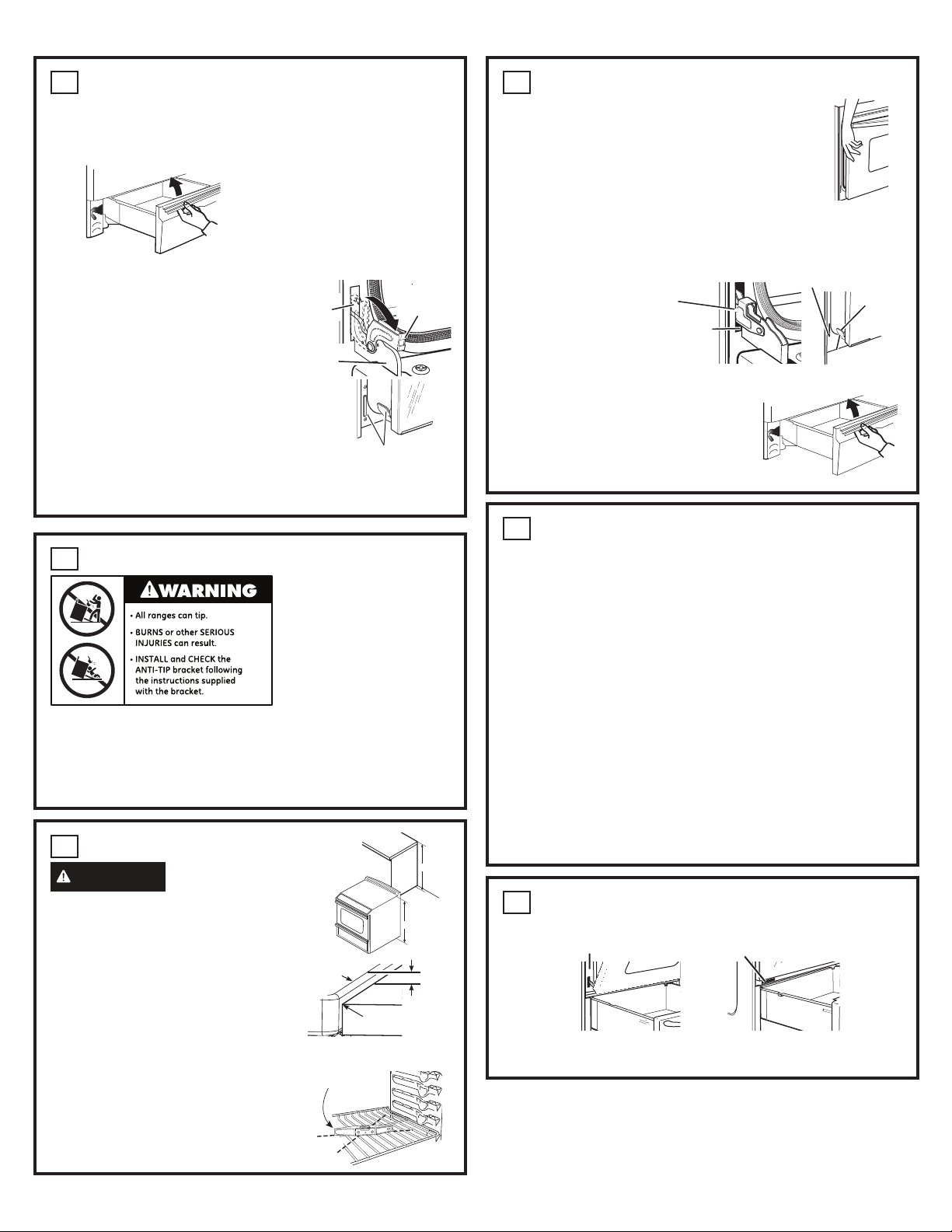
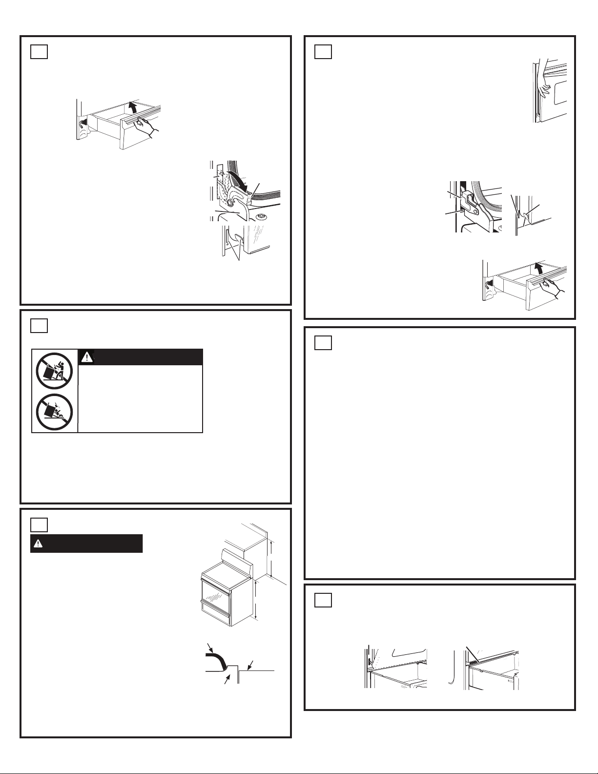
PREPARE THE RANGE
STORAGE DRAWER REMOVAL
A. Pull drawer out until it stops.
B. Lift front of drawer until the stops clear the guide.
C. Pull forward and remove the drawer.
DOOR REMOVAL (optional)
Door removal is not a requirement for installation
of the product but is an added convenience.
To remove the door:
A. Open the oven door as far as it will go.
B. Push both hinge locks down toward the door
frame to the unlocked position. This may require
a flat-blade screwdriver. DO NOT LIFT THE
DOOR BY THE HANDLE!
C. Place hands on both sides of the door, and close
the oven door to the removal position. (Approximately
2.5 cm–5 cm [1"–2"] from the closed position.)
D. Lift door up and out until the hinge arms clear the slots.
NOTE: The oven door is very heavy. Be sure you have a firm grip before
lifting the oven door off the hinges. Use caution once the door is removed.
Do not lay the door on its handle. This could cause dents or scratches.
3
Hinge
unlocked
position
Hinge
slot
Hinge
arm
Hinge clears slot
ANTI-TIP DEVICE INSTALLATION
To reduce the risk of tipping the
range, the range must be secured
by a properly installed anti-tip bracket.
See installation instructions shipped
with the bracket for complete details
before attempting to install.
To check if the bracket is installed
and engaged properly, remove
the storage drawer or kick panel
and look underneath the range to see
that the leveling leg is engaged in the bracket. On models without a storage drawer
or kick panel, carefully tip the range forward. The bracket should stop
the range within
10 cm (4
")
. If it does not, the bracket must be reinstalled. If the range is pulled from
the wall for any reason, always repeat this procedure to verify the range is properly
secured by the anti-tip bracket. Never completely remove the leveling legs or the
range will not be secured to the anti-tip device properly.
4
LEVEL THE RANGE
5
REPLACING THE OVEN DOOR
NOTE: The oven door is heavy. You may need help lifting
the door high enough to slide it into the hinge slots. Do not
lift the door by the handle.
A. Lift the oven door by placing one hand on each side.
The door is heavy, so you may need help. Do not lift
the door by the handle.
B. With the door at the same angle as the removal position
(approximately 2.5 cm–5 cm [1"–2"] from the closed position), seat
the notch of the hinge arm into the bottom edge of the hinge slot.
The notch of the hinge arm must be fully seated into the bottom of the slot.
C. Fully open the door. If the door will not fully open, the indentation
is not seated correctly in the bottom edge of the slot.
D. Push the hinge
locks up against
the front frame
of the oven cavity,
to the locked
position.
E. Close the oven door.
REPLACE THE STORAGE DRAWER
A. Place the drawer rail on the guides. Push
the drawer in until it stops.
B. Lift front of the drawer and push in until
the stops clear the guides.
C. Lower the front of the drawer and push
in until it closes.
6
Hinge notch
Bottom edge of slot
Hinge arm
Hinge in locked
position
Notch of hinge
securely fitted
into bottom
of hinge slot
FINAL INSTALLATION CHECKLIST
• Check to make sure the circuit breaker is closed (RESET) or the circuit fuses
are replaced.
• Be sure power is in service to the building.
• Check that all packing materials and tape have been removed. This will include
tape on metal panel under control knobs (if applicable), adhesive tape, wire ties,
cardboard and protective plastic. Failure to remove these materials could result
in damage to the appliance once the appliance has been turned on and surfaces
have heated.
• Check that the door and drawer are parallel to each other and that both operate
smo
othly. If they do not, see the Owner’s Manual for proper replacement.
• Check to make sure that the rear leveling leg is fully inserted into the anti-tip
bracket and that the bracket is securely installed.
OPERATION CHECKLIST
• Turn on one of the surface units to observe that the element glows within
60 seconds. Turn the unit off when glow is detected. If the glow is not detected
within the time limit, recheck the range wiring connections. If change is required,
retest again. If no change is required, have building wiring checked for proper
connec
tions and voltage.
• Check that the oven control operates
properly. If the oven control does not
operate properly, recheck the wiring connections.
• Be sure all range controls are in the OFF position before leaving the range.
7
MODEL AND SERIAL NUMBER LOCATIONS
The rating plate is located on the oven frame or on the side of the drawer frame.
8
Rating plate
Rating plate
WARNING
Never completely remove
the leveling leg as the range
A. Plug in the unit.
B. Measure the height of your countertop at the
rear of the opening (X).
C. Adjust two rear leveling legs so that the rear
of cooktop is at the same height or higher
than the counter (Y).
D. Slide unit into place.
E. Install oven shelves in the oven and position
the range where it will be installed.
F. Check for levelness by placing a spirit
level on one of the oven shelves. Take two
readings-with the level placed diagonally
first in one direction and then the other.
G. Adjust front leveling legs until the range is level.
H. Look under the unit and verify that the rear leg
is fully engaged with the anti-tip device. If not,
remove the unit and adjust the height of the
rear leg so that it is properly engaged.
Spirit level
NOTE: Cooktop must be at or above counter.
Cooktop
0” or Greater
Counter
X
Y
will not be secured to the anti-tip device properly.
NOTE: Doble Oven models, rating plate is located below front panel.
295D3314P001 REV.2 Pub. No. 29-6178
Orienter la prise électrique pour que la longueur
soit parallèle au plancher.
Il faut éviter d'installer des armoires de rangement au-dessus de la surface de cuisson
afin de réduire les risques de brûlures ou d'incendie lorsqu'on essaie d'atteindre ces
armoires quand les éléments sont brûlants. On peut atténuer ces risques en installant
une hotte de cuisine qui dépasse d'au moins 12,7 cm (5 po) le devant des armoires.
La profondeur des armoires installées au-dessus de la surface de cuisson ne doit pas
être supérieure à 33 cm (13 po).
PREPARE THE OPENING (FOR INDOOR USE ONLY)
2
Si les surfaces du comptoir ne sont pas planes, cela pourrait exercer une tension
excessive sur la surface de cuisson en verre, provoquant un bris et annulant la garantie.
Assurez-vous que le revêtement mural, le comptoir, le plancher et les armoires autour
de la cuisinière sont en mesure de résister à la chaleur (jusqu'à 93 °C [200 °F]) produite
par la cuisinière.
A. Prévoyez un dégagement minimum de 76,2 cm (30 po) entre les éléments de surface
et le dessous non protégé des armoires en métal ou en bois, ou prévoyez un
dégagement minimum de 61 cm (24 po) lorsque le dessous des armoires en bois
ou en métal est protégé par un morceau de carton dur ignifuge d'au moins 6,3 mm
(1/4 po) d'épaisseur, recouvert d'une feuille en métal n° 28 MSG d'au moins 0,38 mm
(0,015 po) d'épaisseur, une pièce d'acier inoxydable de 0,38 mm (0,015 po)
d'épaisseur, d'aluminium de 0,63 mm (0,025 po) d'épaisseur, ou de cuivre de 0,5 mm
(0,020 po) d'épaisseur.
B. Nous recommandons de prévoir un espace d'au moins 15,2 cm (6 po) par rapport
aux surfaces qui se trouvent à moins de 38,2 cm (15 po) au-dessus de la surface
de cuisson et aux armoires adjacentes afin de réduire l'exposition à la vapeur, aux
éclaboussures de graisse et à la chaleur. Prévoyez un jeu d'au moins 6,3 mm
(1/4 po) par rapport au mur arrière.
C. L'épaisseur du comptoir doit être au maximum 3 cm (1.18 po)
ENLÈVEMENT DU MATÉRIEL D'EMBALLAGE
Le fait de ne pas enlever le matériel d'emballage pourrait causer des dommages à l'appareil.
Enlevez tout le matériel d'emballage du four, des grilles, des éléments chauffants et du tiroir
de rangement. Retirez également la pellicule protectrice et les étiquettes sur la porte, la
surface de cuisson (n'enlevez pas les garnitures de protection latérales de la surface
d
e cuisson en verre) et le dosseret. N'enlevez pas le profilé de protection, s'il y a lieu, sur
les côtés de la surface de cuisson en verre. Il sera enlevé plus tard au cours de l'installation.
REMARQUE: Coupez les attaches d'expédition orange du cordon d'alimentation,
en prenant soin de ne pas endommager le cordon.
1
OUTILS NÉCESSAIRES
Perceuse avec foret de 1/8 po
Lunettes de sécurité
Clé à molette
Niveau
Ruban à mesurer
Pince
Tourne-écrou de 1/4 po
Toutes les cuisinières peuvent se
renverser.
Brûleur aux blessures sérieuses
possibles.
Installez et vérifiez le bracket anti-chute
selon es instructions fournisses avec
le bracket.
REMARQUE: Information pour l’installation
seulement à utiliser comme référence.
Regardez instructions d’installation fournisses
avec le produit pour un détail complet et
avant d’essayer de l’installer. Le bracket
anti-chute devra être attache au mur.
Assurez-vous que le component anti-chutes
s’adapte au bracket anti-chute installé au
mur avant de pousser le cuisinière vers le mur.
Armoire adjacente
ou emplacement final
ou panneau latéral
de la cuisinière
Mur
Plancher-bois
Côté de
fixation
Pied de
nivellement
arrière
Plancher-béton
Fixation au mur
Fixation
Plaque
murale
La vis doit
entrer dans le
bois ou le métal
Directives d'installation des cuisinières
électriques encastrées de 30 po
Des questions? Appelez au 1.800.661.1616 ou visitez www.electromenagersGE.ca
AVANT DE COMMENCER
Veuillez lire attentivement toutes les directives qui suivent.
•
IMPORTANT—Conservez les présentes directives pour l'inspecteur local.
•
IMPORTANT—Observez tous les codes et ordonnances en vigueur.
• Note à l'installateur – Veuillez laisser les présentes directives au consommateur.
• Note au consommateur – Veuillez conserver les présentes directives pour
consultation ultérieure.
• Compétences requises – L'installation de cet appareil exige des compétences
de base en mécanique et des compétences avancées en électricité.
• L'installateur est responsable de la qualité de l'installation.
• Toute défaillance du produit attribuable à une installation inadéquate n'est pas
couverte par la garantie.
AVERTISSEMENT : Cet appareil doit être
correctement branché au moyen du cordon d'alimentation fourni, muni d'une fiche.
Si votre cuisine ne dispose pas d'une prise de courant appropriée, vous devez en faire
installer une par un électricien agréé.
30”
Installez la boîte
de sortie de
chaque côté de
la
C
L
36
1
4” ±
1
4”
1
1
8”
47
1
2”
26
7
8”
w/o manipuler
29
1
2”
avec poignée
30”
36
1
4” ±
1
4”
1
1
8”
43
7
8”
26
7
8
”
29
1
2”
25” (63.5 po)
6.98 cm (2 3/4po) -
13.65 cm (5.3/8po)
11.27 cm
(4.44po)
6.98 cm
(2-3/4po)
91.1cm-92.7cm
(35-7/8"-36.5")
du sol qu
comptoir
30¼” - 31”
(76.8 -78.7 po)
DIMENSIONS MINIMUMS ENTRE
LA SURFACE DE CUISSON, LES MURS ET
AU-DESSUS DE LA SURFACE DE CUISSON :
A.
La cuisière doit être placée en
conservant un dégagement minimum
de 12 mm (1/2 po) par rapport
au mur arrière et aux parois latérales
des armoires. Assurez-vous que
le revêtement des murs, les plans
de travail et les placards qui se trouvent
à proximité de la cuisinière peuvent
résister aux températures générées
par la cuisinière (jusqu’à 93,3 °C/200 °F).
B.
Laissez au moins 76,2 cm (30 po)
d’espace entre les éléments de surface
et le bas des placards en métal ou en bois non protégé, ou prévoyez un
minimum de 60 cm (24 po) à condition que le bas de l’armoire de bois ou de
métal soit protégé par un carton à l’enrouleuse ignifuge d’au moins 0,6 cm (1/4 po)
d’épaisseur, recouvert au minimum par l’un des matériaux suivants : tôle No 28
MSG (0,015 po), acier inox 0,015 po, aluminium 0,024 po ou cuivre 0,020 po.
C. Un espacement de 15,2 cm (6 po) par rapport aux surfaces situées
à moins de 38,1 cm (15 po) au-dessus de la table de cuisson est
recommandé afin de réduire l’exposition à la vapeur, la graisse
et la chaleur.
Lorsque vous essayez d’atteindre les armoires au-dessus de la table
de cuisson, vous pouvez éviter les risques de brûlure ou d'incendie
en attendant que les éléments de la table de cuisson se refroidissent,
les espaces d’armoires à rangement au-dessus de la table de cuisson
sont à éviter. S’il y a des armoires à rangement au-dessus de la table
de cuisson, les risques peuvent être moindres en installant une hotte
qui avance d’à peu près 12,7 cm (5 po) au-delà de l’avant des
armoires à rangement. Les armoires installées au-dessus de la table
de cuisson ne peuvent être plus profondes que 33,02 cm (13 po).
B
Deux
côtés
C
A
C
A
w/o manipuler
avec poignée
Arrière de
gamme
Garniture
arrière
Des vis
Pour toutes les installations, installez la garniture arrière requise à l’arrière de la plage
avec 4 vis fournies.
PRÉPARATION DE LA CUISINIÈRE
ENLÈVEMENT DU TIROIR DE RANGEMENT
A. Tirez sur le tiroir jusqu'à ce qu'il bloque.
B. Soulevez l'avant du tiroir pour dégager les butées du guide.
C. Tirez vers vous et enlevez le tiroir.
ENLÈVEMENT DE LA PORTE (facultatif)
Il n'est pas nécessaire d'enlever la porte pour installer
la cuisinière, mais il peut être pratique de le faire.
Pour enlever la porte :
A. Ouvrez complètement la porte du four.
B. Abaissez les deux verrous de charnière vers le
cadre de la porte en position déverrouillée. Vous
aurez peut-être besoin d'un tournevis à lame plate.
NE SOULEVEZ PAS LA PORTE
PAR SA POIGNÉE!
C. Placez vos mains de chaque côté de la porte et refermez-
la jusqu'à la position d'enlèvement (entre 2,5 cm et 5,0 cm
[1 po et 2 po] environ par rapport à la position fermée).
D. Soulevez la porte en la tirant vers vous jusqu'à ce que les
bras de charnière sortent des fentes.
REMARQUE : La porte du four est très lourde. Assurez-vous de bien la tenir avant
de la soulever pour la dégager des charnières. Faites attention après avoir enlevé
la porte. Ne la couchez pas sur sa poignée. Vous pourriez l'égratigner ou la bosseler.
3
Charnière
en position
déverrouillée
Bras de
charnière
Bras de
charnière
Charnière sortie de la fente
INSTALLATION DU DISPOSITIF
ANTIBASCULEMENT
Pour éviter le basculement
accidentel de la cuisinière,
fixez-la en installant de la
façon appropriée le dispositif
antibasculement. Avant
de l'installer, consultez les
directives d'installation
fournies avec le dispositif.
Pour vérifier si ce dispositif
est bien nstallé, enlevez
le tiroir de rangement ou
le panneau inférieur et regardez sous la cuisinière pour voir si le pied de nivellement est bien
engagé dans la fente du dispositif. Sur les modèles sans tiroir de rangement ou panneau
inférieur, penchez doucement la cui
sinière vers l'avant. Le dispositif devrait bloquer la cuisinière
lorsque vous l'inclinez vers l'avant de moins de 10 cm (4 po). Si ce n'est pas le cas, réinstallez
le dispositif antibasculement. Si vous devez éloigner la cuisinière du mur, effectuez toujours
cette procédure pour vérifier si la cuisinière est bien engagée dans le dispositif antibasculement.
Il ne faut jamais complètement enlever les pieds de nivellement sinon, la cuisinière ne sera pas
correctement protégée par le dispositif antibasculement.
4
NIVELEZ LA CUISINIÈRE
5
REMISE EN PLACE DE LA PORTE
DU FOUR
REMARQUE : La porte du four est lourde. Il est possible que vous ayez
besoin d'aide pour la soulever suffisamment pour la faire glisser dans les
fentes de charnière.
A. Soulevez la porte du four en la saisissant de chaque côté. La porte
est lourde et vous aurez peut-être besoin d'aide. Ne soulevez jamais
la porte par sa poignée.
B. En maintenant la porte à la position d'enlèvement (entre 2,5 cm et 5 cm [1 po et 2 po]
par rapport à la position fermée), placez l'encoche du bras de charnière dans le bord
inférieur de la fente de charnière. Le bord inférieur de la fente de charnière doit être
bien inséré dans l'encoche du bras de charnière.
C. Ouvrez complètement la porte. Si la porte ne s'ouvre pas complètement, c'est que
l'encoche du bras de charnière n'est pas correctement placée sur le bord inférieur
de la fente.
D. Relevez les verrous
de charnière jusqu'à ce
qu'ils s'appuient contre
le cadre de la cavité
du four, en position
verrouillée.
E. Refermez la porte du four.
REMISE EN PLACE DU TIROIR DE RANGEMENT
A. Placez les rails du tiroir sur les guides. Poussez
sur le tiroir jusqu'à ce qu'il s'arrête.
B. Soulevez l'avant du tiroir et poussez-le jusqu'à
ce que les butées soient dégagées des guides.
C. Abaissez l'avant du tiroir et poussez-le pour
le fermer.
6
Encoche du bras
de charnière
Bord inférieur de la fente
de charnière
Bras de
charnière
Charnière en
position verrouillée
Encoche du bras de
charnière correctement
placée sur le bord
inférieur de la fente
de charnière
VÉRIFICATION FINALE
DE L'INSTALLATION
•
Assurez-vous de réenclencher le disjoncteur ou de remettre en place les fusibles.
• Assurez-vous que l'alimentation électrique de l'immeuble ou du logement n'est pas
interrompue.
• Assurez-vous que tout le matériel d'emballage et le ruban gommé ont été enlevés.
Cela comprend le ruban gommé sur le panneau en métal sous les boutons de commande
(s'il y a lieu), le ruban adhésif, les attaches-fils, les morceaux de carton et les pièces de
protection en plastique. Si vous n'enlevez pas ce matériel, il pourrai
t causer des dommages
à l'appareil lorsque celui-ci sera mis sous tension et que les surfaces chaufferont.
• Vérifiez si la porte et le tiroir sont parallèles l'un par rapport à l'autre et que les deux
s'ouvrent et se ferment correctement. Sinon, consultez le guide d'utilisation pour effectuer
les ajustements nécessaires.
• Assurez-vous que le pied de nivellement arrière est bien inséré dans le dispositif
antibasculement et que le dispositif a été correctement installé.
VÉRIFICATION DU FONCTIONNEMENT
• Allumez un élément de surface et vérifiez si une lueur est visible dans un délai de
60 secondes. Éteignez l'élément dès que vous apercevez une lueur. Si vous ne voyez
aucune lueur après ce délai, vérifiez les raccordements des fils de la cuisinière. Après avoir
effectué les raccordements nécessaires, vérifiez à nouveau le fonctionnement de l'élément.
Si aucun raccordement n'était nécessaire, faites vérifier si la tension et les raccordements
électriques de l'immeuble ou du logement sont appropriés.
• Vérifiez si la commande du four fonctionne correctement. Si non, vérifiez à nouveau les
raccordements électriques.
• Assurez-vous que toutes les commandes de l'appareil sont à OFF (Arrêt) avant de quitter
la pièce.
7
EMPLACEMENT DES NUMÉROS
DE MODÈLE ET DE SÉRIE
La plaque signalétique se trouve sur le cadre du four ou sur le côté du tiroir
de rangement.
8
Plaque signalétique
Plaque signalétique
AVERTISSEMENT
• Tous les modèles peuvent basculer.
• Cela pourrait causer de GRAVES
BLESSURES ou BRÛLURES.
• INSTALLEZ et VÉRIFIEZ le dispositif
ANTIBASCULEMENT en suivant les
directives fournies avec le dispositif.
AVERTISSEMENT
N’enlevez jamais
entièrement le pied
de nivèlement ou bien la cuisinière ne sera pas fixée
correctement au dispositif anti-renversement.
A. Branchez l'appareil.
B. Mesurez la hauteur de votre comptoir à l’arrière de
l’ouverture (X).
C. Ajustez les deux pieds de nivèlement arrière afin
que l’arrière de la surface de cuisson soit à la
même hauteur ou plus élevé que le comptoir (Y).
D. Glissez l’appareil en place.
E. Installez les grilles du four dans le four et positionnez
la cuisinière là où elle sera installée.
F. Vérifiez l’égalité en plaçant un niveau sur une des
grilles du four. Prenez deux lectures- premièrement
avec le niveau placé diagonalement dans un sens
et puis dans l’autre.
G. Ajustez les pieds de nivèlement avant jusqu’à ce
que la cuisinière soit nivelée.
H. Regardez sous l’appareil et vérifiez que le pied
arrière soit complètement enclenché avex le
dispositif anti-renversement. Si non, retirez
l’appareil et ajustez la hauteur du pied arrière
afin qu’il soit correctement enclenché.
X
Y
NOTE : La surface de
cuisson doit être à la même
Grille
Surface de cuisson
Comptoir
hauteur ou plus élevée que le
comptoir.
Remarque: les modèles Doble Oven, plaque signalétique se trouvent sous le
panneau avant.