Loading ...
Loading ...
Loading ...
4 | English
SITE PREPARATION
Preparation
WARNING
To avoid a hazard due to instability of the appliance, it
must be xed in accordance with the instructions.
Uncrate the unit and inspect for damage. Remove the wood
base and discard shipping bolts and brackets. Remove and
recycle packing materials. Do not discard the kickplate, anti-
tip bracket and hardware.
Remove the kickplate by extracting the two mounting
screws. Refer to the illustration below.
Anti-Tip Bracket
WARNING
To prevent the unit from tipping forward, the anti-tip
bracket must be installed.
The back of the anti-tip bracket must be installed 610 mm
from the front of the unit (without panels).
Use all anti-tip bracket hardware as instructed for wood or
concrete oors.
IMPORTANT NOTE: For wood or concrete oor applications,
if the #12 screws do not hit a wall stud or wall plate, use the
#8 screws and #12 washers with the wall anchors.
IMPORTANT NOTE: In some installations the subooring or
nished oor may necessitate angling the screws used to
fasten the anti-tip bracket to the back wall.
SCREW
Kickplate removal
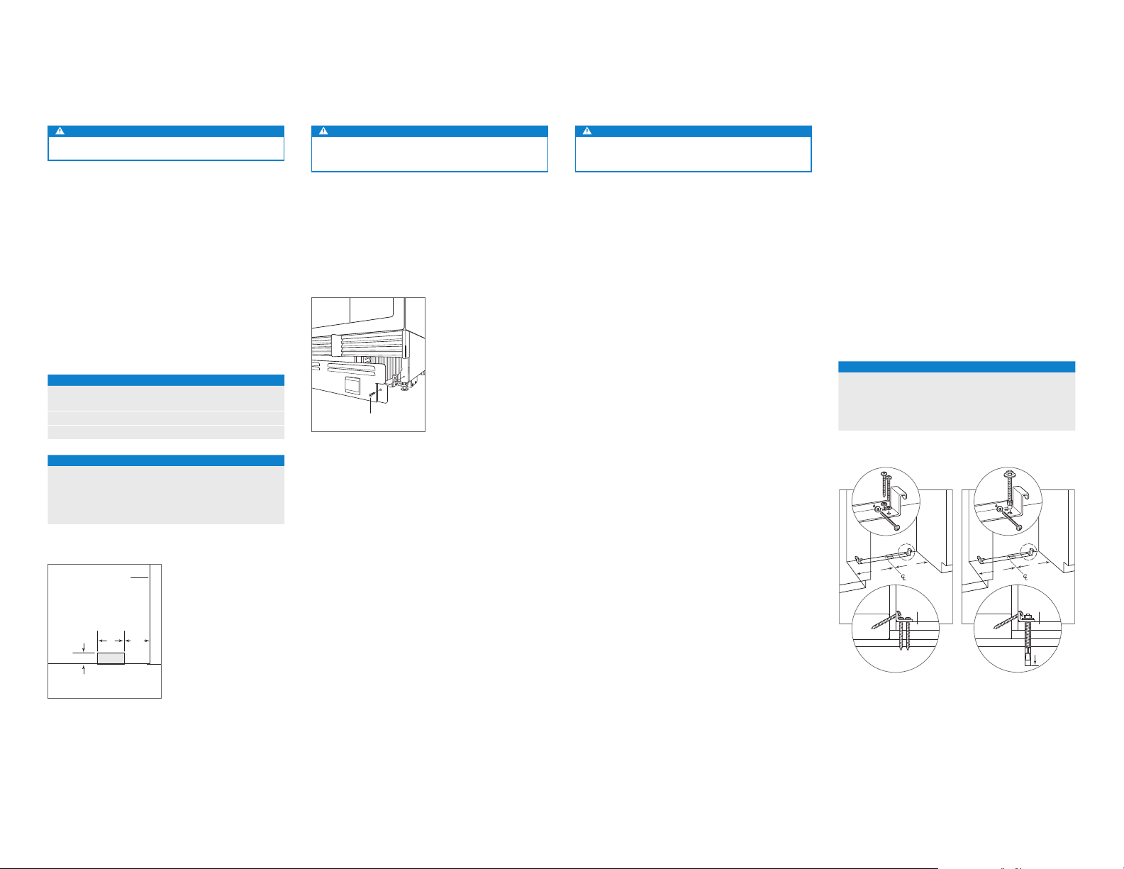
WOOD FLOOR APPLICATION
After properly locating the anti-tip bracket in the opening,
drill pilot holes 5 mm diameter maximum in the wall studs or
wall plate. Use the #12 screws and washers to secure the
brackets. Verify the screws penetrate through the ooring
material and into wall studs or wall plate a minimum of 19
mm. Refer to the illustration and chart below.
CONCRETE FLOOR APPLICATION
After properly locating the anti-tip bracket in the opening,
drill pilot holes 5 mm diameter maximum in the wall studs
or wall plate. Drill 10 mm diameter holes into the concrete a
minimum of 38 mm deep. Use the #12 screws and washers
to secure the brackets to the wall, and use the
3
/8" wedge
anchors to secure the brackets to the oor. Verify the screws
penetrate wall studs or wall plate a minimum of 19 mm.
Refer to the illustration and chart below.
ANTI-TIP BRACKET PLACEMENT
WIDTH A
457 mm Models 229 mm
610 mm Models 305 mm
762 mm Models 381 mm
914 mm Models 457 mm
A
A
SUBFLOORING
WOOD FLOOR
WALL PLATE
FINISHED
FLOORING
A
A
SUBFLOORING
CONCRETE
FLOOR
WALL PLATE
FINISHED
FLOORING
38 mm
min
Wood oor
Concrete oor
Plumbing
WARNING
Connect to potable water supply only.
Installation must comply with all applicable plumbing codes.
The water supply line should be located within the shaded
area shown in the illustrations below. The water supply line
should be connected to the house supply with an easily
accessible shut-off valve. Do not use self-piercing valves.
The water supply line must be ush to the oor and not
interfere with installation of the anti-tip bracket.
An in-line lter is required for models with an ice maker or
water dispenser when water conditions have a high sedi-
ment content.
A reverse osmosis system can be used provided there
is constant water pressure of 2.4–8.3 bar supplied to the
unit at all times. A copper line is not recommended for this
application.
PLUMBING REQUIREMENTS
Water Supply Line
1
/4" OD copper, braided
stainless steel or PEX tubing
Water Pressure 2.4–8.3 bar
Excess Water Line for Connection .9 m
WATER SUPPLY LOCATION
WIDTH A
457 mm Models 76 mm
610 mm Models 140 mm
762 mm Models 152 mm
914 mm Models 229 mm
76 mm
FRONT VIEW
FLOOR
TOP VIEW
BACK WALL
13 mm
152
mm
A
WATER
LINE
A
152
mm
RIGHT SIDE
OF OPENING
RIGHT
SIDE OF
OPENING
Water supply location
Loading ...
Loading ...
Loading ...