
Loading ...
Loading ...
Loading ...
INSTALLATION
8
NOTICE:
Since the tightly wound tape is the only means
of keeping water out of the splice, the eciency of the
splice will depend on the care used in wrapping the tape.
NOTICE: For wire sizes larger than #8, (7mm
2
) use a sol-
dered joint rather than Scotchl putty.
Wire Splicing
Splice wire to motor leads using only copper wire for
connections to pump motor and control box.
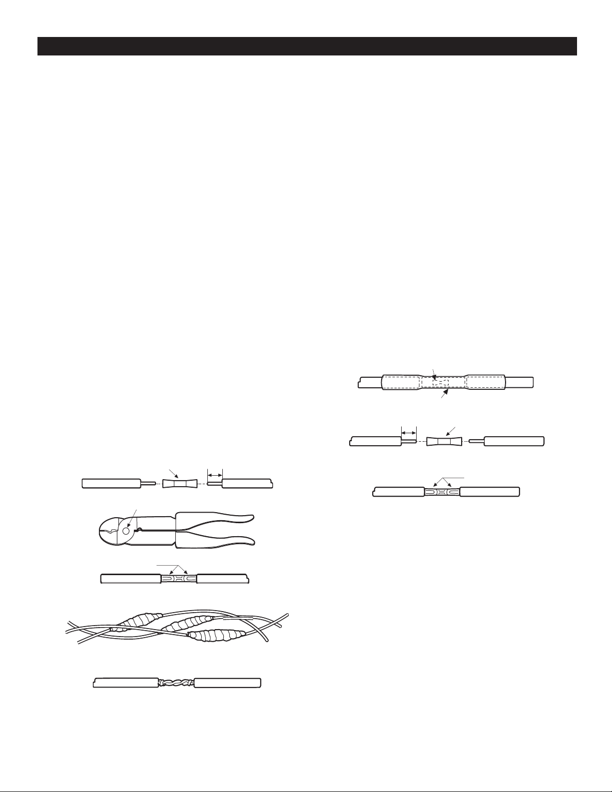
1. Tapered splice (Wire sizes No. 8 and larger):
A. Cut motor lead staggering lead and wire length
so that second lead is 2” longer than rst lead and
third lead is 2” longer than second.
B. Cut o power supply wire ends. Match colors and
lengths of the wires to colors and lengths of motor
leads.
C. Trim installation back 1/2” from supply wire and
motor lead ends.
D. Insert motor lead ends and supply wire ends into
butt connectors. Match wire colors between supply
wires and motor leads.
E. Using crimping pliers, indent butt connector lugs to
attach wire.
F. Cut electrical “Scotchl™” or equivalent insulation
putty into three equal parts and form tightly around
butt connectors. Be sure Scotchl™ overlaps
insulted part of wire.
G. Using #33 Scotch™ or equivalent tape, wrap each
joint tightly; cover wire for about 1-1/2” on each
side of joint. Make four passes with the tape. When
nished you should have four layers of tape tightly
wrapped around the wire. Press edges of tape
rmly down against the wire.
NOTICE: Since tightly wound tape is the only
means of keeping water out of splice, eciency of
splice will depend on the care used in wrapping the
tape.
NOTICE: For wire sizes larger than No. 8, use
soldered joint rather than Scotchl™ putty.
2. Heat shrink splice
[for wire sizes #14, 12 and AWG (2,3 and 5mm)]
A. Remove 3/8” insulation from ends of motor leads
and power supply wires.
B. Put plastic heat shrink tubing over motor leads
between power supply and motor.
C. Match wire colors and lengths between power
supply and motor.
D. Insert supply wire and lead ends into butt
connector and crimp. Match wire colors between
power supply and motor. Pull leads to check
connections.
E. Center tubing over butt connector and apply heat
evenly with torch (match or lighter will not supply
enough heat).
NOTICE: Keep torch moving. Too much concen-
trated heat may damage tubing.
3. Mechanical Splice Kit with plastic insulators (for 14, 12
and 10 Gauge AWG Wire (2, 3 and 5mm):
A. Cut motor leads staggering lead and wire length so
that 2nd lead is 4” (101.6mm) longer than 1st lead and
3rd lead is 4” (101.6mm) longer than second.
B. Cut wire ends matching colors and lengths of wires
between power supply and motor.
C. Trim insulation back 1/2” (12.7mm) from power supply
wire and motor lead ends.
D. Unscrew plastic caps from insulators. Place a cap
and neoprene gasket sleeve on each wire to be
spliced.
E. Slide insulator body onto one wire end.
F. Insert wire end into butt connector and crimp.
Match wire colors between power supply and motor
G. Center insulator body over splice and slide gasket
sleeves into body as far as they will go. Screw caps
onto insulator body and tighten by hand for a strong,
waterproof splice.
Notch
1/2” (12.7mm)
1/2” (12.7mm)
Indent here
Connector
Butt Connector
Heat Shrink Tubing
Butt Connector
Indent here
Completed Splice
Alternate Method
twist and solder
Loading ...
Loading ...
Loading ...