Loading ...
Loading ...
Loading ...
Installation Manual 55
ENGLISH
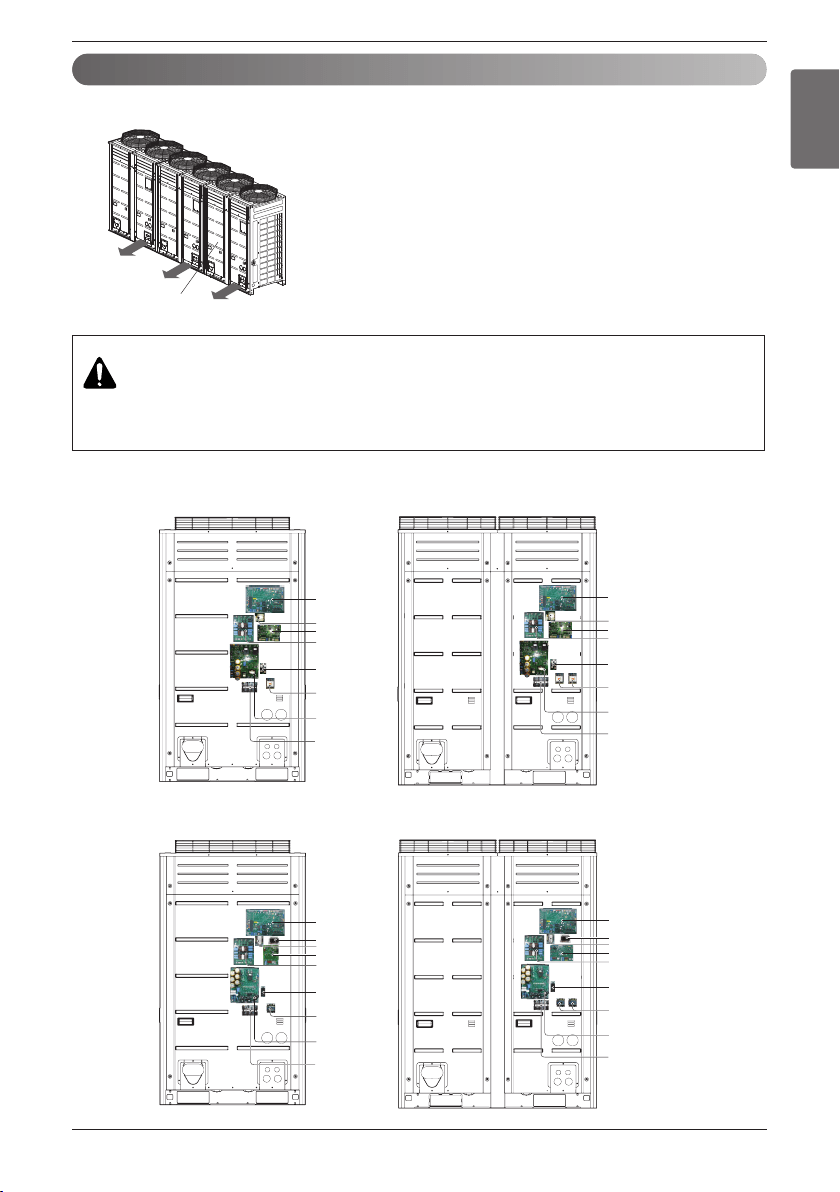
Electrical Wiring
Control box and connecting position of wiring
- Remove all of the screws at front panel and remove the panel by pulling it forward.
- Connect transmission line between main and sub outdoor unit through the
terminal block.
- Connect transmission lines between outdoor unit and indoor units through
the terminal block.
- When the central control system is connected to the outdoor unit, a dedi-
cated PCB must be connected between them.
- When connecting transmission line between outdoor unit and indoor units
with shielded wire, connect the shield ground to the earth screw.
WARNING
The temperature sensor for outdoor air should not be exposed to direct sunlight.
- Provide an appropriate cover to intercept direct sunlight.
Front Panel
UX3
UX2
Main PCB
Fan PCB
Noise filter
Bridge diode
Magnet switch
Inverter PCB
Take care of the phase
sequence of 3-phase 3-wire
power system
Take care of the phase
sequence of 3-phase 3-wire
power system
Main PCB
Reactor
Fan PCB
Noise filter
Bridge diode
Magnet switch
Inverter PCB
Reactor
UX3
UX2
Main PCB
Fan PCB
Noise filter
Bridge diode
Magnet switch
Inverter PCB
Take care of the phase
sequence of 3-phase 3-wire
power system
Take care of the phase
sequence of 3-phase 3-wire
power system
Main PCB
Reactor
Fan PCB
Noise filter
Bridge diode
Magnet switch
Inverter PCB
Transformer
Reactor
Transformer
n 3Ø 208/230V
n 3Ø 460V
Loading ...
Loading ...
Loading ...