Loading ...
Loading ...
Loading ...
Owner’s Manual - RADS-183P, 253P, RAD-283M, REG-183M, 253M
11
INSTALLATION INSTRUCTIONS
6. Install chassis into cabinet by following all
steps in Step 8 of Window Mounting.
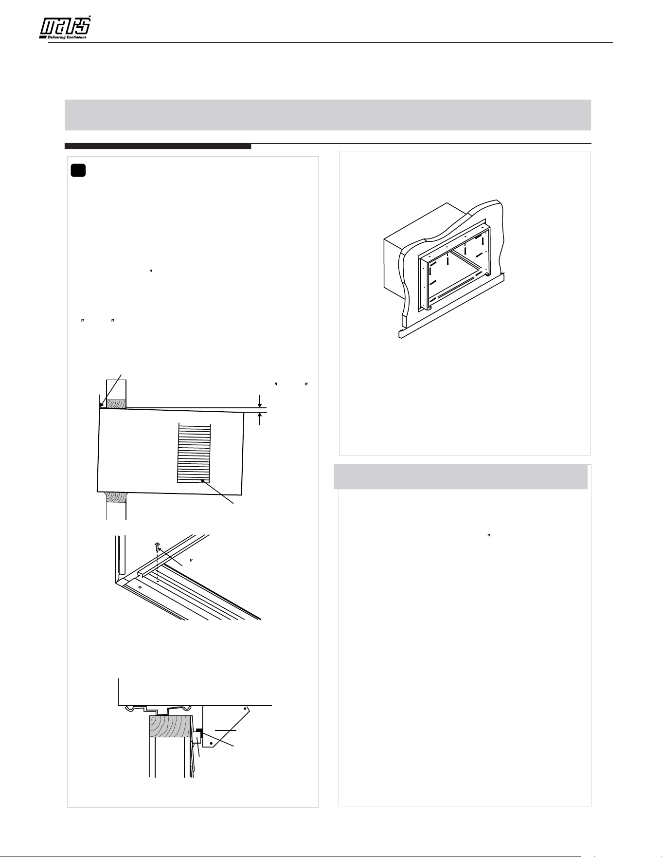
1. Cut or build a wall opening in the masonry wall
similar to the frame construction (refer to Step
2 of Thru-the-wall Installation for a wall
thickness greater than 8-1/2 ).
2. Secure cabinet in place using masonry nails,
or the right masonry anchor screws. (Another
way to do this is to build an in-between frame
of 2x4 s as shown in the Step 2 Prepare Wall
illustrations-but make it double framed on
either side, and install between masonry wall
opening and cabinet. Frame must be securely
anchored to maso
nry wall opening). This way
gives very good louver clearance on either
side of cabinet.
3. Install a lintel to support masonry wall above
cabinet. Existing holes in cabinet can be used
and/ or additional holes can be drilled to fasten
cabinet at various positions. Be sure that side
louver clearance is in accordance with Step 1
above.
4. Install exterior cabinet support brackets as
shown in Step 2 of Thru-the-wall installation.
Caulk or flash if needed, to provide a weather-
tight seal around top and sides of cabinet.
5. To complete installation, apply wood trim
molding a
round room side projection of cabinet.
C.Masonry Construction
,
5. Screw or nail cabinet wooden frame using
shims if frame is oversized, to eliminate
distortion. See Fig.8.Remember to maintain
proper slop as described in Step 3.
Fig.8
OPTIONAL: Caulking and installation of trim on
interior wall may be done. You can buy wood from
your local number or hardware supply. On the
outside, caulk openings around top and sides of
cabinet, and all sides of wood sleeve to the opening.
NOTE: See Step 5, Item 3 of Window Mounting
Instructions for bottom rail seal location.
3
Prepare and Install Cabinet
1. Slide chassis from cabinet. Refer back to Step
one of Window Mounting.
2. Place cabinet into opening with bottom rail
resting firmly on bottom board of wooden
frame.
3. Position cabinet to achieve proper slope for
water removal.(See Fig.5 below.)
4. Secure bottom rail to wood frame with two large
wood screws 1 (2.5cm) long using the two holes
in the bottom of the channel resting on frame.
(See Fig.6 ).
Fig.5
Side Louvers
1 Long Wood
Screw
Fig.6
Refer to Step 5 of Window Mounting for assembly
of support brackets. A wooden strip nailed to the
outside wall should be used in conjunction with
sill support angle brackets.
Support bracket
Sill angle bracket
Fig.7
NOTE: Check that air conditioner is tilted back about
1 5 O O
1 / to 1 / (tilted about 3 t o 4 downward t oth e o utside).
4 8
After proper installation, condensate should not drain
from the overflow drainh ole d uringn ormalu se,c orrect
the slope otherwise (Fig.14).
1 5
About1 / to 1 /
4 8
Measure from
the cabinet edge.
11
Loading ...
Loading ...
Loading ...