Loading ...
Loading ...
Loading ...
6
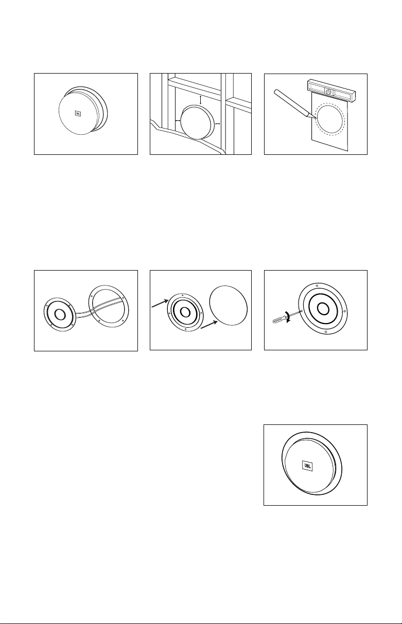
SP6CII, SP6CSII, SP8CII
EXISTING CONSTRUCTION
Remove the grille from the
speaker frame by pulling on
the paper tab. If the tab is
missing, to avoid scratching
the grille or baffle you may
unfold a paper clip, insert the
straight end through one of
the holes in the grille, and
gently pull up.
≥
1/2"
≥
1/2"
≥
1/2"
Cut the drywall.
Note: Always allow at least
one-half inch between a wall
stud and the speaker cutout or
the locking tabs will not be able
to swivel into place.
Connect the speaker wires to
the speaker. Model SP6CSII
requires two sets of speaker
wires, one for each channel.
Place the frame assembly
in the wall.
Screw down each of the four
Phillips head screws. The
locking tabs will swivel into
place and secure the unit to
the rear surface of the drywall.
Replace the metal grille.
Determine the correct speaker
location.
Note: Remove the inner template,
which is the paint shield, at the
perforation. Use the outer tem-
plate when cutting the drywall.
The SoundPoint speakers fea-
ture unique swivel mounts for
the tweeters that enable you
to aim the very directional
high frequencies toward the
listening position, at ear-level
height. Before installing the
speaker grille, gently press on
the outer edge of the tweeter
mount to adjust the position of
the tweeter. The tweeter will
not swivel more than 15
degrees in any direction; do
not attempt to force it to move
further. You may also rotate
the tweeter to orient the JBL
logo as desired.
The dual tweeters of the
SP6CSII speaker may be
swiveled independently.
Optimum imaging will be
obtained by aiming the
tweeters to the left and right
of the listening position, at
ear
-level height, if your
application permits.
Soundpoint OM SP5-6-6C-8-8 7/7/06 9:36 AM Page 6
Loading ...
Loading ...