
Backset is the distance from the door edge to the center of the hole on
the door face. Master Lock commercial deadbolts are supplied with a
2-3/8" to 2-3/4” backset.
Le retrait représente la distance entre le rebord de la porte et le centre
du trou sur la face de la porte. Les pênes dormants de qualité commerciale
Master Lock sont offerts avec un retrait de 60mm ou 70mm.
La distancia de entrada es la distancia desde el borde de la puerta hasta el
centro del agujero en la cara de la puerta. Las cerraduras comerciales
Master Lock se suministran con cierres de distancia de entrada de 60mm
o de 70mm.
Backset / Retrait / Distancia de entrada
Replacing an Existing Lock
Remplacement d’une serrure existante
Reemplazar una cerradura existente
Install strike and tighten screws.
Insérer la gâche puis serrer les vis.
Instale la placa de cierre y apriete los tornillos.
Install strike / Installer la gâche / Instale la placaInstall latch / Installer le verrou / Instale el cierre
Insert latch and tighten screws.
Insérer le verrou puis serrer les vis.
Inserte el cierre y apriete los tornillos.
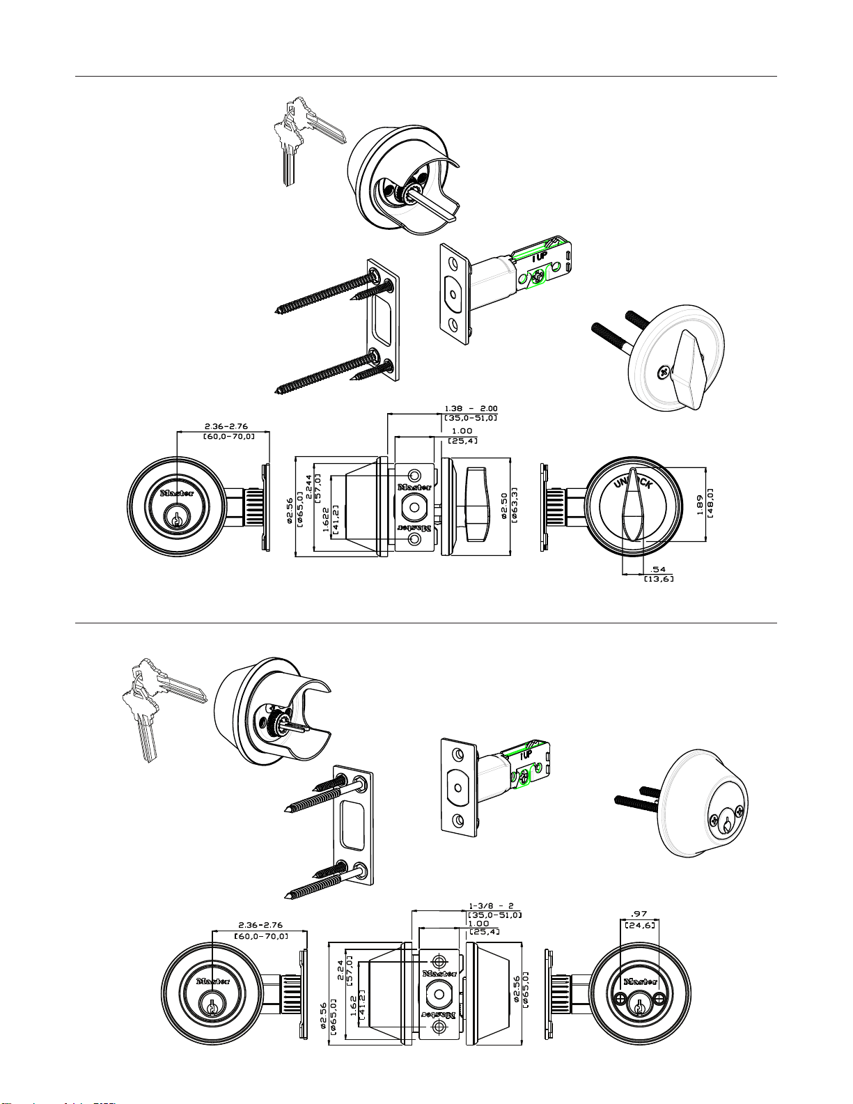
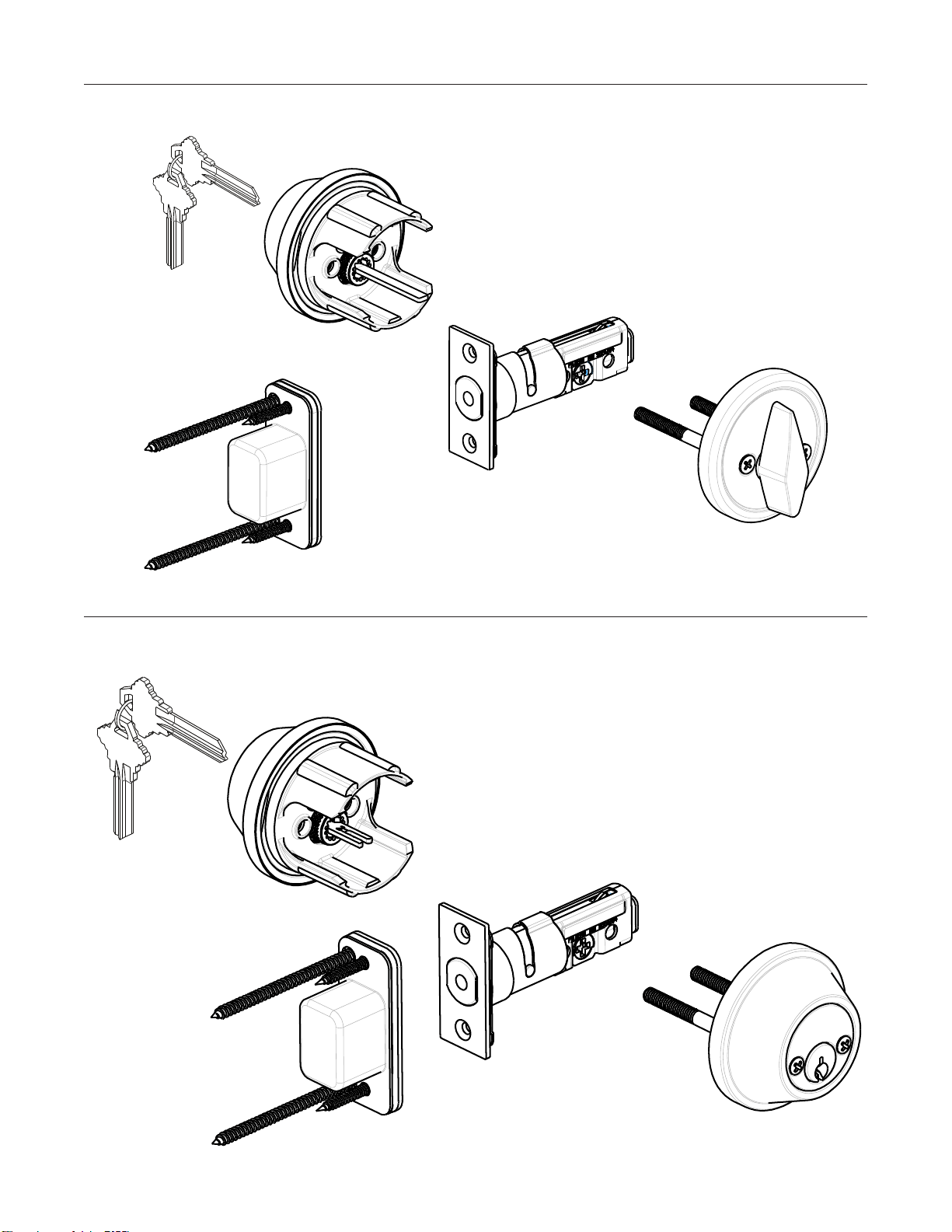
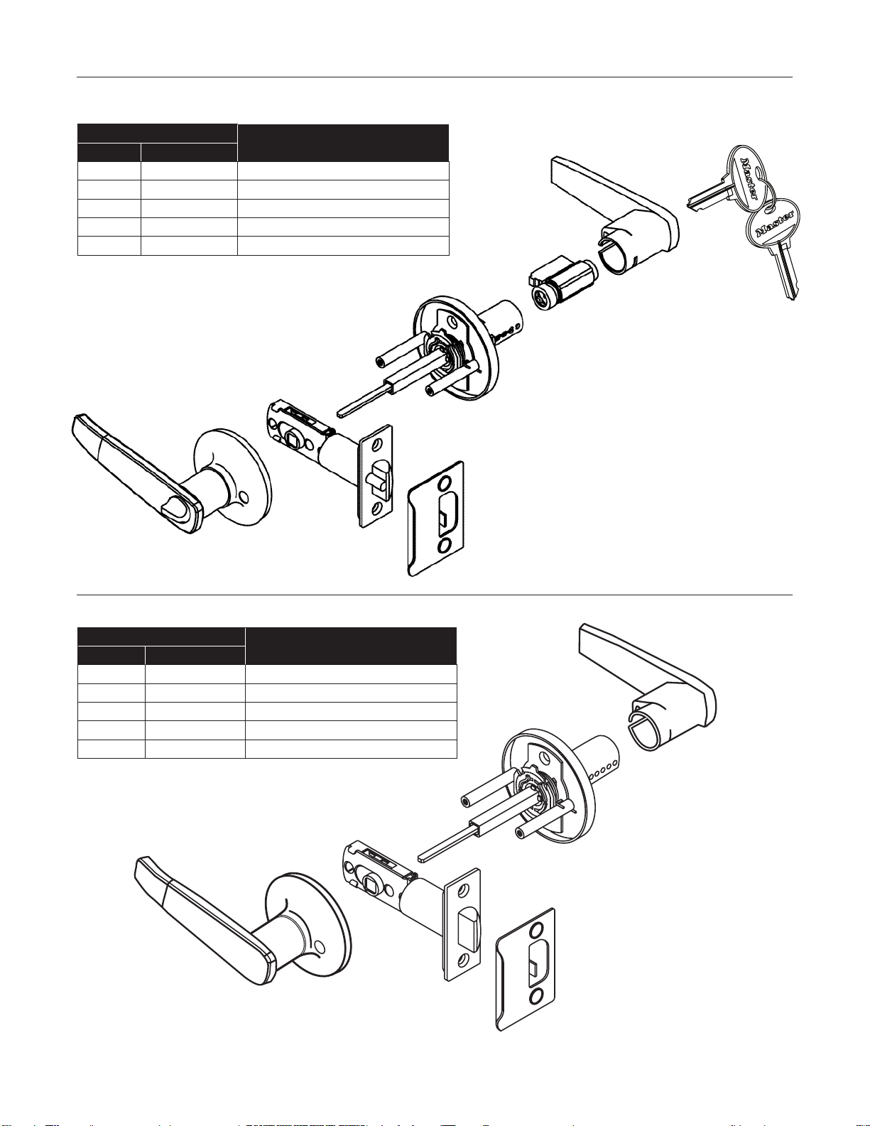
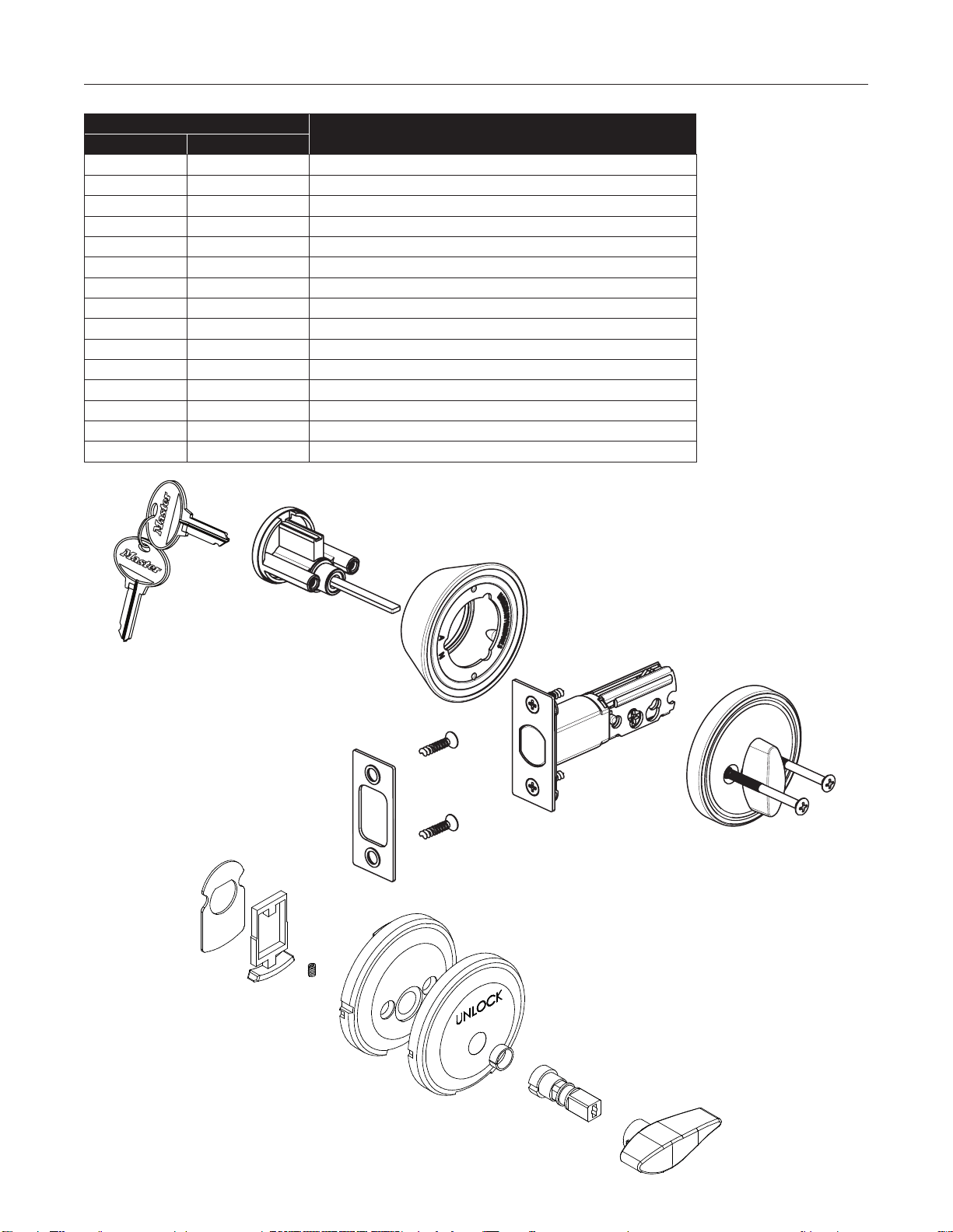
Install single cylinder / Installer le barillet simple / Instale el cilindro simple
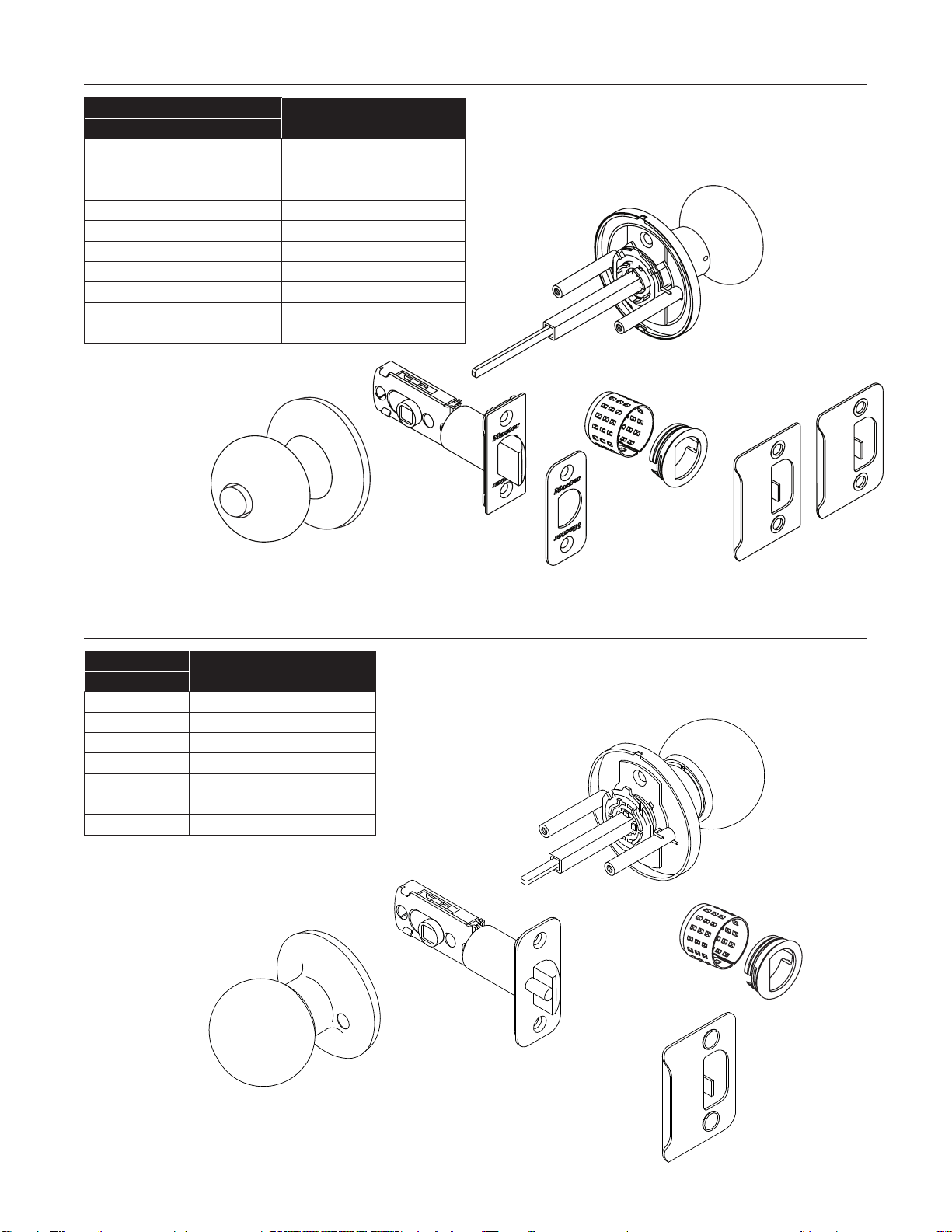
1. Retract deadbolt to unlocked position.
2. Insert exterior tail piece horizontally through latch crank.
3. Press exterior cylinder flush against door.
4. Install inside turn unit and tighten installation screws
1. Rétracter le pêne dormant à la position de déverrouillage.
2. Insérer la tige de commande extérieure horizontalement
dans le fouillot du pêne.
3. Appuyer le cylindre extérieur à plat contre la porte.
4. Insérer le tourniquet interne puis serrer les vis.
1. Retraiga el pestillo con resorte a la posición destrabada.
2. Inserte la pieza de cola exterior horizontalmente
por la manivela del cierre.
3. Presione el cilindro exterior al ras contra la puerta.
4. Instale la unidad de giro interior y apriete
los tornillos de instalación.
EXTERIOR TAIL PIECE
TIGE DE COMMANDE EXTÉRIEURE
PIEZA DE COLA EXTERIOR
INSIDE TURN UNIT
TOURNIQUET INTERNE
UNIDAD DE GIRO INTERIOR
EXTERIOR CYLINDER
CYLINDRE EXTÉRIEUR
CILINDRO EXTERIOR
EXTERIOR CYLINDER
CYLINDRE EXTÉRIEUR
CILINDRO EXTERIOR
INSTALLATION SCREW
VIS DE MONTAGE
TORNILLO DE INSTALACIÓN
LATCH CRANK
FOUILLOT DU PÊNE
MANIVELA DEL CIERRE
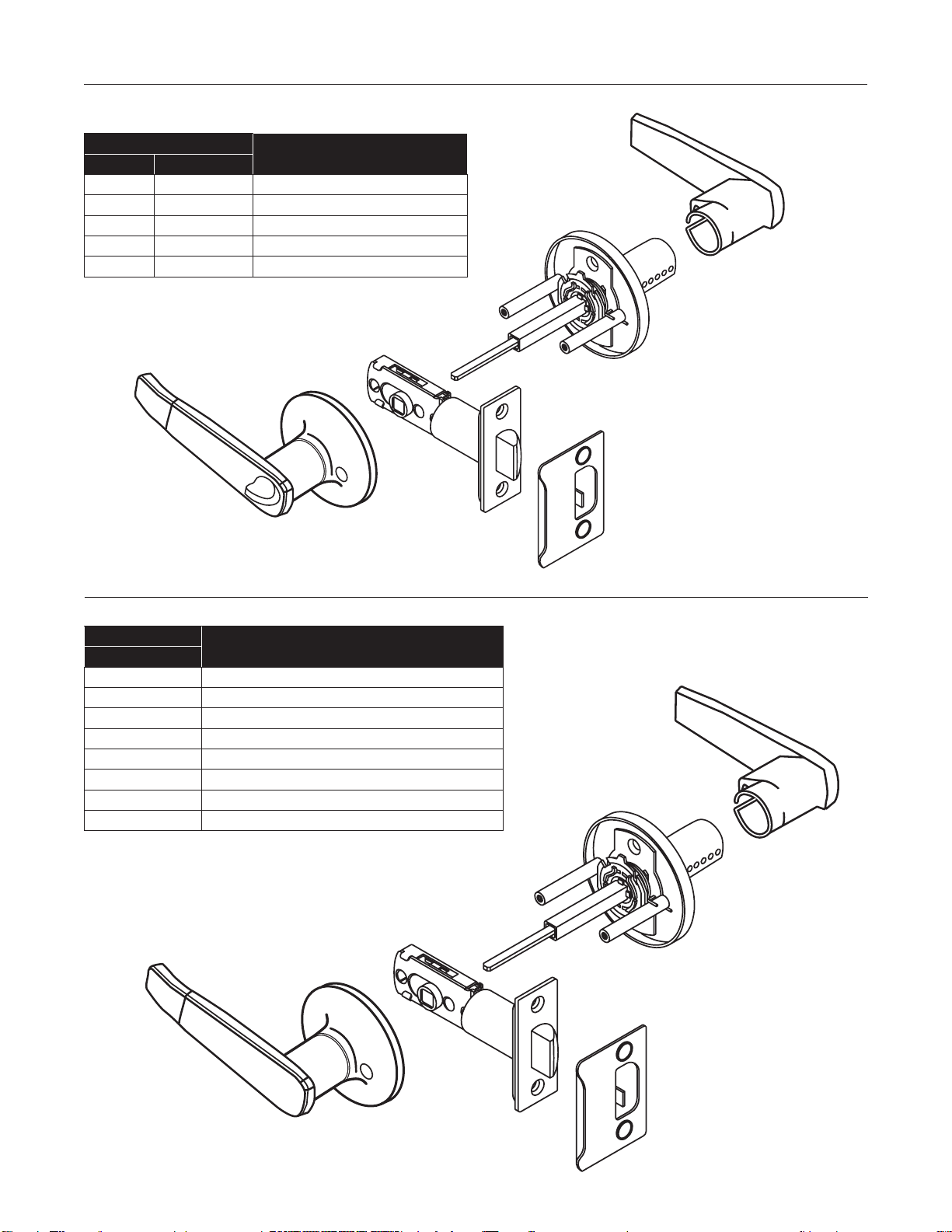
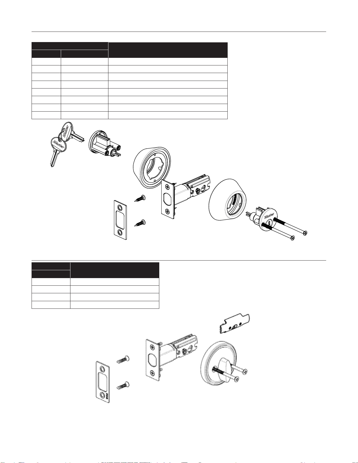
1. Retract deadbolt to unlocked position.
2. Insert exterior tail piece horizontally through latch crank.
3. Press exterior cylinder flush against door.
4. Insert interior tail piece vertically through latch crank.
5. Press interior cylinder flush against door and tighten installation screws.
1. Rétracter le pêne dormant à la position de déverrouillage.
2. Insérer la tige de commande extérieure horizontalement dans le fouillot du pêne.
3.Appuyer le cylindre extérieur à plat contre la porte.
4. Insérer la tige de commande intérieure à la verticale à travers le fouillot du pêne.
5.Appuyer le cylindre intérieur à plat contre la porte puis serrer les vis de montage.
1. Retraiga el pestillo con resorte a la posición destrabada.
2. Inserte la pieza de cola exterior horizontalmente por la manivela del cierre.
3. Presione el cilindro exterior al ras contra la puerta.
4. Inserte la pieza de cola interior verticalmente por la manivela del cierre.
5. Presione el cilindro interior al ras contra la puerta y
apriete los tornillos de instalación.
Install double cylinder / Installer le barillet double / Instale el cilindro doble
INTERIOR CYLINDER
CYLINDRE INTÉRIEURE
CILINDRO INTERIOR
EXTERIOR CYLINDER
CYLINDRE EXTÉRIEUR
CILINDRO EXTERIOR
EXTERIOR CYLINDER
CYLINDRE EXTÉRIEUR
CILINDRO EXTERIOR
INSTALLATION SCREW
VIS DE MONTAGE
TORNILLO DE INSTALACIÓN
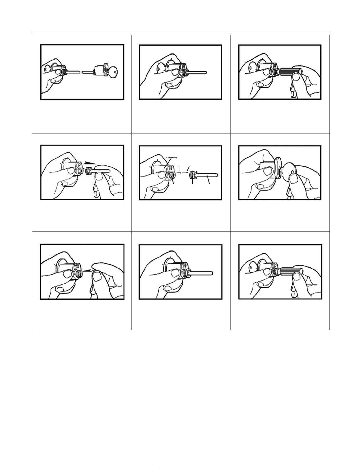
CORRECT WAY
BONNE FAÇON
MANERA CORRECTA
WRONG WAY
MAUVAISE FAÇON
MANERA INCORRECTA
LATCH CRANK
FOUILLOT DU PÊNE
MANIVELA DEL CIERRE
For existing lock replacement:
Before beginning installation,
check that backset on lock
matches backset on door.The
backset of new lock is stated
on front of package. If backset
is different, replace with
proper backset.
Para reemplazar la
cerradura existente: Antes
de comenzar la instalación,
revise que la distancia de
entrada de la cerradura
concuerde con la distancia
de entrada de la puerta. La
distancia de entrada de la
nueva cerradura aparece en
la parte delantera del
paquete. Si es diferente,
cambie el producto por otro
con la distancia de entrada
correcta.
Remplacement d’une serrure
existante: Avant de commencer
l’installation, vérifier que le
retrait de la serrure corresponde
à celui de la porte. Le retrait de
la nouvelle serrure est indiqué
sur le devant de l’emballage. Si
le retrait diffère de celui de la
porte, utiliser un modèle au
retrait approprié.
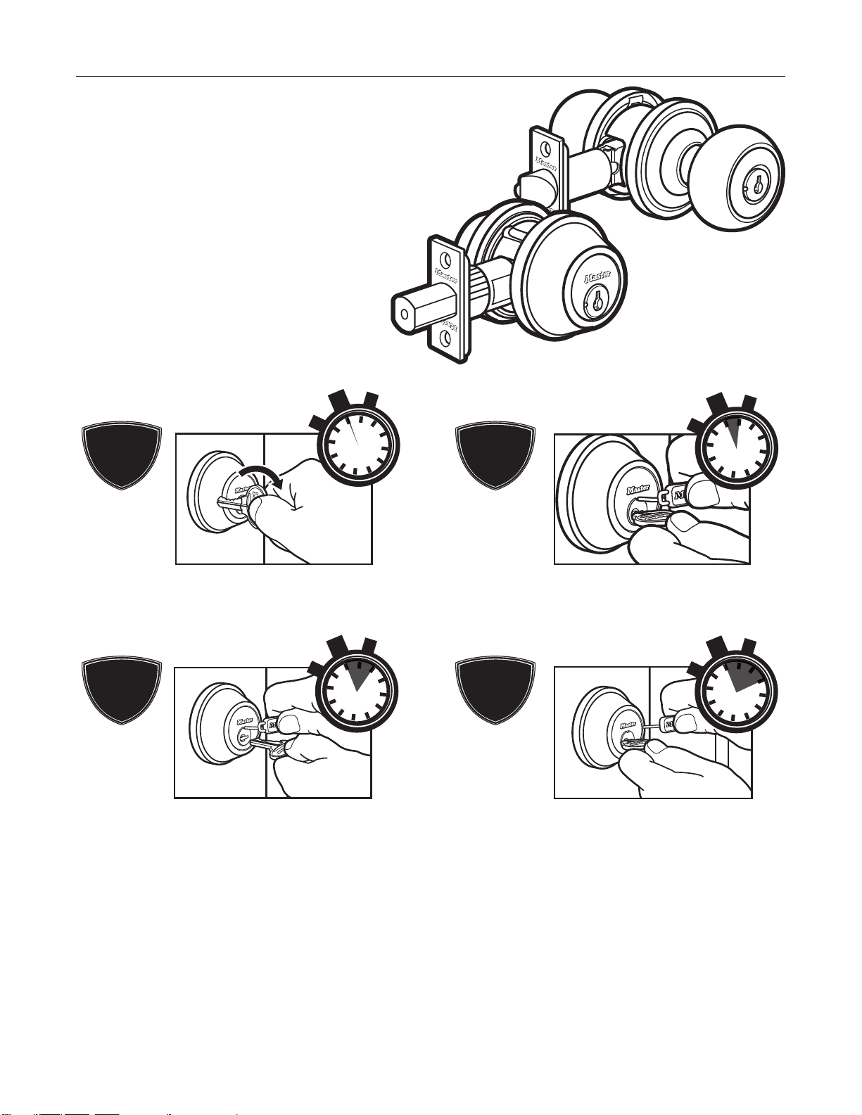
Upon installation of lock, it may happen that key hole will be in the upper or lower part of the cylinder as shown in
illustration. It is advisable to position the correct key hole to be in the lower part.
Une fois la serrure installée, l’entrée de clé peut se trouver dans la partie supérieure ou inférieure du barillet,tel qu’illustré ici. Il est
préférable que l’entrée de clé soit dans la partie inférieure.
Al instalar la cerradura, puede ocurrir que el ojo de la llave esté en la parte de arriba o abajo del cilindro como se muestra en la
ilustración. Es recomendable corregir el ojo de la llave para que quede en la parte de abajo.
Correct keyway position / Orientation appropriée de l’entrée de clé / Posición correcta del ojo de la llave
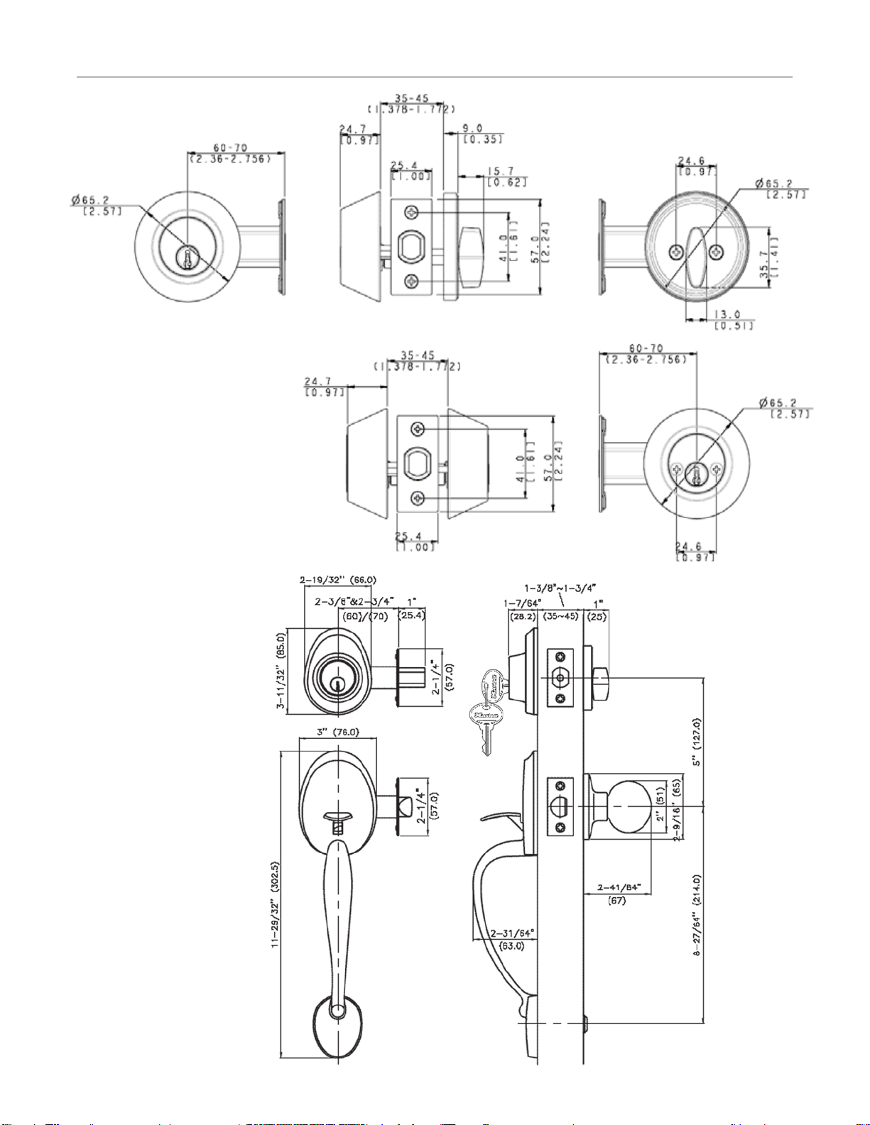
For use on doors 1-3/8" to 1-3/4" thick
Tools required for replacing existing lock(s):
1, Phillips head screwdriver
Tools required for new construction:
1, Phillips head screwdriver
1, 2-1/8" hole saw
1, 1" drill
1, Chisel
Pour les portes de 35mm à 45mm d’épaisseur
Outils requis pour le remplacement
de la serrure existante :
1, Tournevis Phillips
Outils requis pour la nouvelle installation :
1, Tournevis Phillips
1, Scie-cloche de 54mm
1, Perceuse de 25.4mm
1, Ciseau
Para usar en puertas de
35mm a 45mm de espesor
Herramientas necesarias para un reemplazo:
1, Destornillador punta Phillips
Herramientas necesarias para construcción nueva:
1, Destornillador punta Phillips
1, Sierra caladora de 54mm
1, Taladro de 25.4mm
1, Cincel
Instructions for Installation of Commercial Grade
Single or Double Cylinder Deadbolts
Instructions d’installation de serrures à pêne dormant à cylindre
simple ou double de qualité commerciale
Instrucciones de instalación de las cerraduras de cilindro simple y
doble de calidad comercial
10 Year Limited Warranty for Master Lock Door Hardware
Master Lock warrants to the original consumer purchaser for 10 years from date of purchase, that if this product fails during normal use due to a defect in materials or workmanship during this period, Master Lock Company will repair, replace or provide replacement
parts, free of charge.Simply contact Master Lock at 1-800-308-9244 or at www.masterlock.com for replacement or replacement parts information. All other purchasers (including purchasers for industrial, commercial and business use) are warranted for a period of 5
years from the original date of purchase (the "Warranty Period" for non-homeowners). Proof of purchase (original sales receipt) must accompany all warranty claims.This warranty is extensive in that it covers replacement of all defective parts and finishes. However
normal wear,damage due to installation error, product abuse, product misuse,other alterations,or use of cleaners containing abrasives,alcohol or other organic solvents,whether performed by a contractor, service company,or yourself,are excluded from this warranty.
Master Lock will not be responsible for labor charges and/or damage incurred in installation, repair or replacement,nor for any indirect, incidental or consequential damages,losses,injury or costs of any nature relating to this lock. TO THE EXTENT PERMITTED BY LAW,
MASTER LOCK COMPANY DISCLAIMS ALL OTHER IMPLIED OR EXPRESS WARRANTIES INCLUDING ALL WARRANTIES OF MERCHANTABILITY AND/OR FITNESS FOR A PARTICULAR PURPOSE.
LIMITATION OF LIABILITY:This warranty is your sole remedy and Master Lock Company shall not be liable for any damages, whether direct, indirect,incidental, special, consequential,exemplary, or otherwise, including lost revenues and lost profits, arising out of any
theory of recovery,including statutory, contract or tort. Notwithstanding the term of any express or implied warranty, or in the event that any warranty fails of its essential purpose, in no event will Master Lock Company’s entire liability exceed the purchase price of this
product. Some states, provinces,and nations do not allow the exclusion or limitation of incidental or consequential damages so the above limitations or exclusions may not apply to you. This limited warranty gives you specific legal rights, and you may also have other
rights which vary from state to state, province to province, and nation to nation.
Garantie limitée de 10 ans pour les serrures de porte Master Lock
Master Lock Company garantit à l’acheteur original, pour une période de 10 ans à partir de la date d’achat, que si ce produit présente un défaut de matériau ou de fabrication au cours de cette période, Master Lock Company le remplacera, le réparera ou en fournira
les pièces de rechange, sans frais.Il vous suffit de communiquer avec Master Lock au (800) 308-9244 ou d’aller au www.masterlock.com pour obtenir des renseignements sur le remplacement ou les pièces de rechange du produit.Tous les autres acheteurs (y
compris les acheteurs à des fins industrielles, professionnelles ou commerciales) bénéficient d’une garantie de 5 ans à partir de la date d’achat original (la « période de garantie » pour les utilisations non domestiques). La preuve d’achat (reçu de vente original) doit
accompagner toutes les réclamations de garantie. Cette garantie est étendue,à qu’elle couvre le remplacement de tous les finis et toutes les pièces défectueuses. Toutefois, une usure normale,des dommages causés par une erreur d’installation, un usage abusif ou
fautif du produit, d’autres modifications ou l’usage de nettoyants contenant des abrasifs, de l’alcool ou d’autres solvants organiques,qu’il soit effectué par un entrepreneur,une entreprise de services ou vous-même, est exclus de la présente garantie. Master Lock
n’est pas responsable des frais de main-d’ouvre ou des dommages causés par l’installation, la réparation ou le remplacement du produit, ni de quelque dommage indirect, accessoire ou immatériel,perte, blessure ou coûts de quelque nature reliés à cette serrure.
JUSQU’AU DEGRÉ PERMIS PAR LA LOI,MASTER LOCK COMPANY REJETTE TOUTE AUTRE GARANTIE EXPRESSE OU IMPLICITE,Y COMPRIS TOUTES LES GARANTIES DE COMMERCIALISATION ET/OU D’APTITUDE À UN USAGE PARTICULIER.
LIMITATION DE RESPONSABILITÉ : Cette garantie constitue votre unique recours,et Master Lock Company n’est responsable d’aucun dommage, qu’il soit direct,indirect,accessoire, particulier,immatériel, exemplaire ou autre, y compris les revenus et bénéfices perdus,
provenant de toute théorie de recouvrement, y compris statutaire,par contrat ou provenant d’un acte dommageable. Nonobstant l’existence de toute garantie explicite ou implicite,ou dans l’éventualité où toute garantie faille à son rôle de base, la responsabilité entière
de Master Lock Company ne dépassera en aucun cas le prix d’achat payé pour ce produit. Certains états, provinces et nations ne permettent pas l’exclusion ni la restriction des dommages indirects ou accessoires; les exclusions ou restrictions décrites ci-dessus
peuvent donc ne pas vous être applicables. La présente garantie limitée vous confère des droits légaux spécifiques,lesquels peuvent varier d’une province,d’un état ou d’une nation à l’autre.
Garantía limitada a 10 años para cerraduras de puertas Master Lock
Master Lock garantiza al comprador original durante 10 años desde la fecha de compra, que si falla este producto durante el uso normal debido a un defecto en materiales o fabricación en cualquier momento durante este período,Master Lock Company reparará,
sustituirá o proporcionará piezas de repuesto, sin cargo alguno.Simplemente póngase en contacto con Master Lock llamando al 1-800-308-9244 o visite www.masterlock.com para obtener información sobre piezas de repuesto o sustituciones.Todos los demás
compradores (incluidos los compradores para uso industrial,comercial y de negocios) cuentan con garantías de 5 años a partir de la fecha de compra original (el "Período de garantía" para no propietarios).El comprobante de compra (recibo original de venta) debe
acompañar a todo reclamo bajo la garantía.Esta garantía es amplia porque cubre la sustitución de todas las piezas y acabados con defectos. Sin embargo, quedan excluidos de esta garantía el uso normal, el daño debido a errores de instalación, maltrato del producto,
uso indebido del producto, otras alteraciones,o uso de limpiadores que contengan abrasivos, alcohol u otros solventes orgánicos, ya sea que lo realice un contratista,una empresa de servicios o usted mismo. Master Lock no será responsable de cargos por mano de
obra y/o daños a esta cerradura que se incurran al instalar,reparar o sustituir componentes, ni de ningún daño, pérdida,lesión o costo indirecto, fortuito o consecuente, de la naturaleza que sea.
EN LA MEDIDA QUE LO PERMITA LA LEY, MASTER LOCK COMPANY DESCONOCE TODA OTRA GARANTÍA IMPLÍCITA O EXPRESA, INCLUIDAS TODAS LAS GARANTÍAS DE COMERCIABILIDAD O IDONEIDAD PARA UN FIN PARTICULAR.
LIMITACIÓN DE RESPONSABILIDAD: Esta garantía es su exclusiva reparación y Master Lock Company no será responsable de ningún daño, ya sea directo,indirecto, fortuito, especial,consecuente, ejemplar o de otro tipo, incluida la pérdida de ganancias o réditos, que
surja de alguna teoría de recuperación, sea estatutaria,contractual o de agravio. No obstante el plazo de una garantía expresa o implícita,o en caso de que alguna garantía limitada falle en su objetivo esencial, la responsabilidad civil total de Master Lock Company no
excederá bajo ninguna circunstancia el precio de compra de este producto. Algunos estados, provincias y países no permiten la exclusión o limitación de daños fortuitos o consecuentes, de modo que las limitaciones o exclusiones anteriores pueden no corresponder a
su caso. Esta garantía limitada le concede derechos legales específicos,y usted puede tener también otros derechos que varían de un estado, provincia o país a otro.
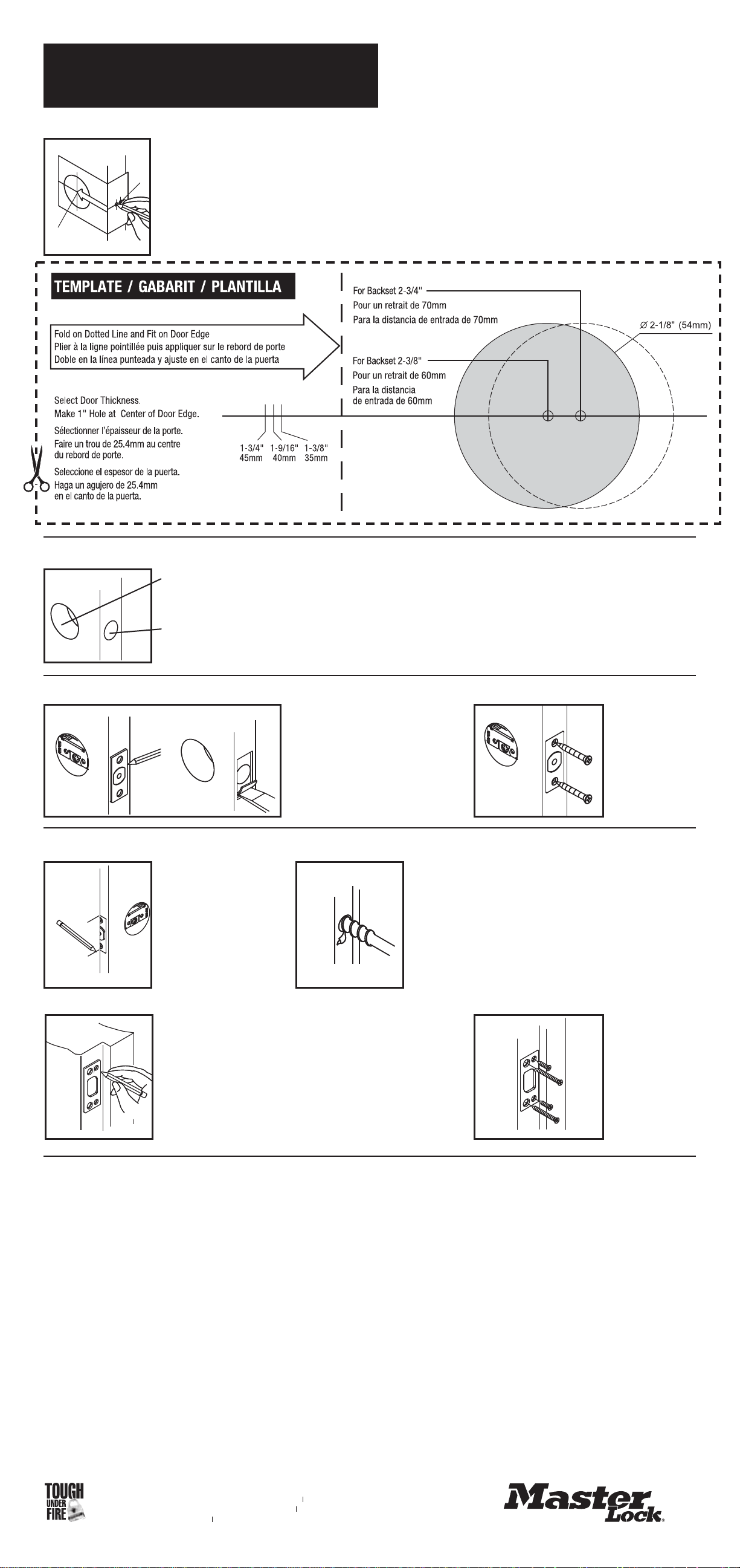
Measure one half of door thickness from doorstop and mark for the
vertical centerline of strike. Drill 1" hole, 1" deep at the intersection
of the horizontal and vertical centerlines.
Mesurer une moitié d’épaisseur de porte à partir de l’arrêt de porte
puis marquer la ligne de centre verticale de la gâche. Percer un trou
de 25.4mm de diamètre et 25.4mm d’épaisseur à l’intersection des
lignes de centre verticale et horizontale.
Mida la mitad del espesor de la puerta desde el tope de la puerta y
marque la línea central vertical de la placa de cierre.Taladre un
agujero de 25.4mm, a 25.4mm de profundidad en la intersección de
las líneas centrales horizontal y vertical.
Close door to mark horizontal
centerline of strike.
Fermer la porte pour tracer
la ligne de centre
horizontale de la gâche.
Cierre la puerta para marcar
la línea central horizontal de
la placa de cierre.
Mark door with template / Marquer la porte avec le gabarit / Marque la puerta con la plantilla
Drill holes / Percer les trous / Taladre los agujeros
Select 2-3/8" or 2-3/4" backset as desired and mark center of holes on door face.
Choisir le retrait désiré, soit 60mm ou 70mm, puis marquer le centre des trous sur la face de la porte.
Seleccione una distancia de entrada de 60mm o de 70mm según lo desee y marque el centro del
agujero en la cara de la puerta.
NOTE: backset on door must be the same as backset of latch.
REMARQUE: Le retrait de la porte doit être le même que celui du verrou.
NOTA: La distancia de entrada de la puerta debe ser la misma que la distancia de entrada del cierre.
Drill 2-1/8" hole on door face from both sides to avoid wood splitting.
Percer un trou de 54mm sur la face de la porte; percer des deux côtés pour éviter que le bois ne se fende.
Taladre el agujero de 54mm en la cara de la puerta, desde ambos lados de la misma,para evitar que se parta la madera.
Drill 1" hole for latch.
Percer un trou de 25.4mm pour le verrou.
Taladre un agujero de 25.4mm para los cierres.
New Construction Preparation
Préparation pour une nouvelle installation
Preparación de construcción nueva
Insert latch in hole, mark outline of face
plate and chisel 11/64" deep.
Insérer le verrou dans le trou, marquer
le contour de la têtière et ciseler à
4mm de profondeur.
Inserte el cierre en el agujero, marque
el contorno de la placa frontal y cincele
a 4mm de profundidad.
Install strike and
tighten screws.
Insérer la gâche
puis serrer les vis.
Instale la placa de
cierre y apriete
los tornillos.
Match screw holes on strike with vertical centerlines on jamb. Mark
outline of strike plate and chisel out until strike is flush with jamb.
(Approx. 5/64")
Aligner les trous de vis sur la gâche avec les lignes de centre sur le
montant de porte. Marquer le contour de la gâche et creuser au ciseau
jusqu’à ce que la gâche soit à égalité avec le montant (environ 2mm).
Haga coincidir los agujeros de tornillos de la placa de cierre con las líneas
centrales en la jamba. Marque el contorno de la placa de cierre y cincele
hasta que ésta quede al ras con la jamba. (Aproximadamente 2mm)
Insert latch and
tighten screws.
Insérer le verrou
puis serrer les vis.
Inserte el cierre y
apriete los
tornillos.
Install strike / Installer la gâche / Instale la placa
Install latch / Installer le verrou / Instale el cierre
w w w . m a s t e r l o c k . c o m
Master Lock Company LLC, Milwaukee, WI 53154 U.S.A. 800-308-9244
Master Lock Canada, Oakville, Ontario L6H 5S7 Canada 800-227-9599
© 2007 Master Lock Company All Rights Reserved
77777 05/07
Door Hardware
Technical Manual
Version 4.12


BumpStop
®
Advanced Cylinder Technology ................2
Door Hardware Codes ................................3
GRADE 2 RESIDENTIAL..............................4
NightWatch
®
Function ................................5
Standard NightWatch
®
Deadbolt ........................6
Combination NightWatch
®
Deadbolt......................6
Electronic Keypad NightWatch
®
Deadbolt..................7
Electronic Keypad NightWatch
®
Deadbolt Rekeying ..........8
Deadbolt Information .................................9
GRADE 2 COMMERCIAL ............................16
Communicating Door Deadbolt ........................17
Entry Knobset .....................................18
Passage Knobset ...................................18
Privacy Knobset....................................19
Classroom Knobset .................................19
Storeroom Knobset .................................20
Entry Leverset .....................................21
Passage Leverset ..................................21
Privacy Leverset ...................................22
Classroom Leverset .................................22
Storeroom Leverset .................................23
Heavy Duty Entry Leverset............................23
Heavy Duty Passage Leverset .........................24
Heavy Duty Privacy Leverset ..........................24
Heavy Duty Storeroom Leverset........................25
Heavy Duty Classroom Leverset .......................25
Single Cylinder Deadbolt .............................26
Double Cylinder Deadbolt.............................26
Heavy Duty Single Cylinder Deadbolt ....................27
Heavy Duty Double Cylinder Deadbolt ...................27
GRADE 3 RESIDENTIAL.............................28
Knob Styles .......................................28
Lever Styles.......................................29
Deadbolt and Handleset Styles ........................30
Entry Knobset .....................................31
Passage Knobset ...................................31
Privacy Knobset....................................32
Storeroom Knobset .................................32
Knobset Rekeying ..................................33
Entry Leverset .....................................35
Passage Leverset ..................................35
Privacy Leverset ...................................36
Storeroom Leverset .................................36
Leverset Rekeying ..................................37
Handleset ........................................39
Single Cylinder Deadbolt .............................40
Double Cylinder Deadbolt.............................41
One Sided Deadbolt .................................41
Deadbolt Rekeying..................................42
RECODABLE MULTI-FAMILY.........................43
Introduction/How to Recode ..........................43
Entry Knobset .....................................44
Passage Knobset...................................45
Privacy Knobset....................................46
Single Cylinder Deadbolt .............................47
Double Cylinder Deadbolt.............................47
SERVICE KITS ....................................48
TABLE OF CONTENTS
1
Product Page Product Page
The BumpStop
®
advanced cylinder technology is standard equipment in all Grade 2 lock
products. Because of the cylinder design, it cannot be offered as an option in the Grade
3 products.
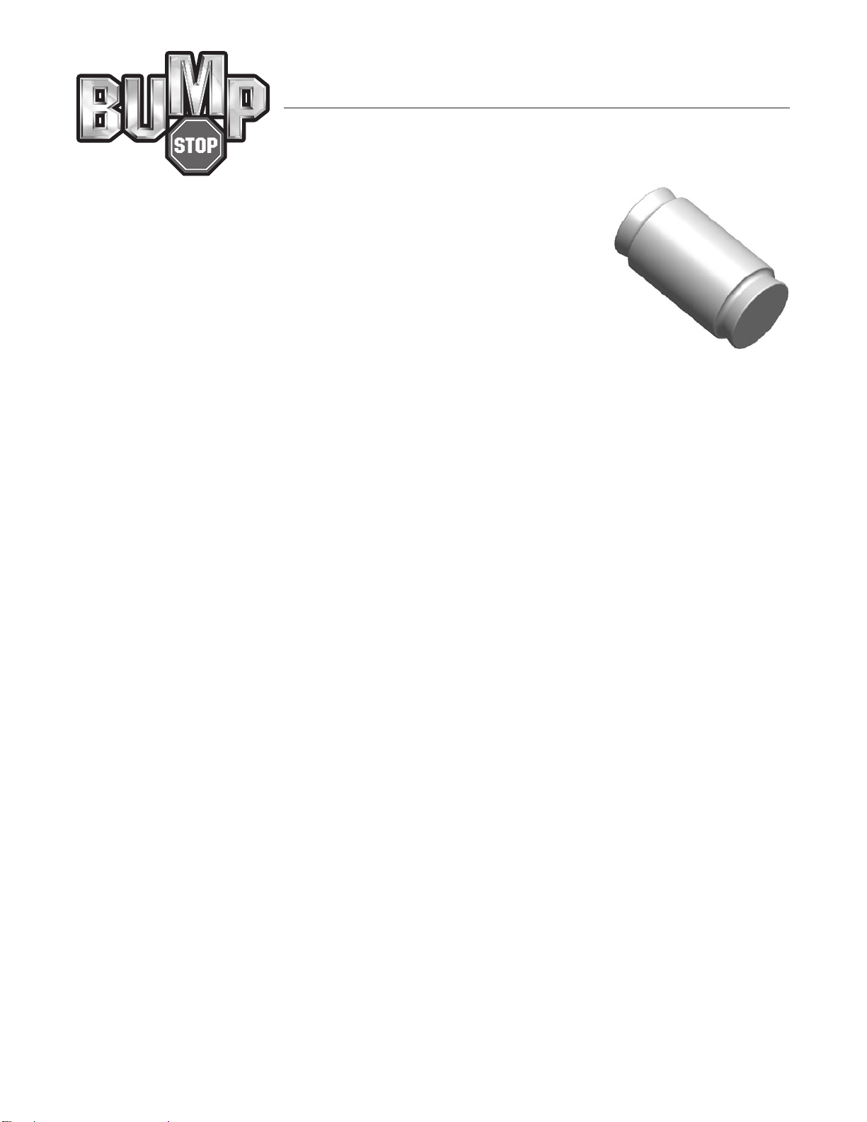
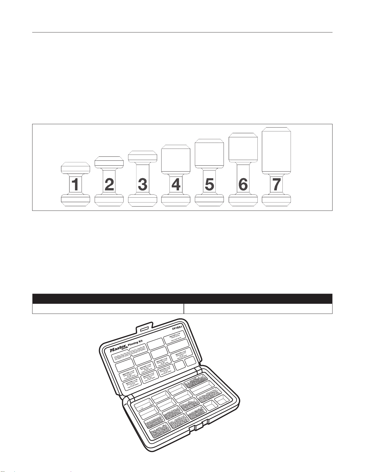
One primary component of BumpStop
®
technology is a special stainless steel driver pin
shown at the right. Only one of these special pins is required in a cylinder to make it
bump resistant, but in some cylinders we actually place two to eliminate the potential for
someone to develop a systematic method of defeating the BumpStop
®
technology.
Cylinders that are compatible with the BumpStop
®
pin have been specially manufactured
to exacting specifications, and consequently, our BumpStop
®
pins may not be used
effectively to prevent a bump attack in other cylinders. In fact, our BumpStop
®
pins may
not be used in retrofit door hardware cylinders that were supplied by us prior to July 2008,
or in other manufacturers’ cylinders.
The current proposed ASTM standard for bump resistance has a highest grade level of 6, and to qualify for that level of
resistance a number of cylinders must each successfully withstand 60 bump impacts without operating. Master Lock
routinely subjects our test cylinders to 240 impacts without losing any of the bump resistance.
The location of the BumpStop
®
pin within the cylinder is a critical factor for the bump resistance. The last column of the
table on the next page indicates which depths of cut must be associated with the location of the BumpStop
®
pin in the
cylinder.
Cylinders keyed at our factory have the bible marked to indicate the month and year they were produced and a number
indicating which chamber contains the BumpStop
®
pin(s). When rekeying, consult the table and relocate the BumpStop
®
pin
in the appropriate pin chamber for your new combination.
Master Lock uses ITL key machines to produce door hardware keys to original manufacturer specifications. We also can
take your existing bittings from a MK system and regenerate your entire system including all designed expansion. A copy
of that expanded bitting list in both places allows you to select the exact keys you desire and be assured that they will be
produced as you want them.
Because there may not be a constant cut of the correct depth for the specific brand, some MK system locks for existing
systems cannot be BumpStop
®
compatible.
Master Lock also sells these cylinders Zero Bitted if you prefer to do your own keying. In those cases you can use the part
number map on page 16 to determine the correct part number for the keyway you desire.
The BumpStop
®
pin will always be located in the 5th pin chamber in Zero Bitted locks for your convenience. Simply relocate
the pin to the appropriate pin chamber for a compatible depth of cut as shown in the table on page 3. Zero Bitted cylinders
will not have markings on the bible for the BumpStop
®
pin location.
BumpStop
®
ADVANCED CYLINDER TECHNOLOGY
2
®

3
Brand
Number
of Pins First Code Last Code ITL#
BumpStop
®
Compatible
Cuts
Arrow
®
5 10T1001 10T5668 027 0 – 1 – 2
Corbin
®
59A1 5 01T1001 01T6404 113 1 – 2 – 3
Corbin
®
59A1 6 01V10001 01V42433 113 1 – 2 – 3
Corbin
®
60 5 29T1001 29T9252 126 0 – 1 – 2
Corbin
®
60 6 29V10001 29V61173 126 0 – 1 – 2
Corbin
®
Russwin
®
L4 5 07T1001 07T3420 122 1 – 2
Corbin
®
Russwin
®
L4 6 07V1001 07V9995 122 1 – 2
Harloc
®
, Lori
®
L200, Sargent
®
S, Sargent
®
U 5 02T1001 02T6399 388 1 – 2 – 3
Kwikset
®
, Master
®
5 12T1001 12T3658 265 1 – 2 – 3
Lockwood
®
5 08T1001 08T9252 266 0 – 1 – 2
Lockwood
®
6 08V10001 08V61173 266 0 – 1 – 2
Lori
®
80 5 80T1001 80T6399 271 1 – 2 – 3
Lori
®
90 6 90V10001 90V42432 271 1 – 2 – 3
Master
®
/Dexter
®
5 32T1001 32T2728 142 0 – 1 – 2
Russwin
®
981/852 5 11T1001 11T3221 378 0 – 1
Russwin
®
D1 5 30T1001 30T9252 379 0 – 1 – 2
Russwin
®
D1 6 30V10001 30V61173 379 0 – 1 – 2
Sargent
®
LA-LC 5 36T1001 36T6399 388 1 – 2 – 3
Sargent
®
LA-LC 6 36V10001 36V42432 388 1 – 2 – 3
Sargent
®
RA-RC 5 70T1001 70T6399 388 1 – 2 – 3
Sargent
®
RA-RC 6 70V10001 70V42432 388 1 – 2 – 3
Schlage
®
C, Schlage
®
P 5 04T1001 04T9252 391 0 – 1 – 2
Schlage
®
C, Schlage
®
P 6 04V10001 04V61173 391 0 – 1 – 2
Schlage
®
E 5 34T1001 34T9252 391 0 – 1 – 2
Schlage
®
E 6 34V10001 34V61173 391 0 – 1 – 2
Segal
®
5 27T1001 27T3420 395 0 – 1 – 2
Weiser
®
5 13T1001 13T9252 167 0 – 1 – 2
Weslock
®
5 33T1001 33T9252 468 0 – 1 – 2
Yale
®
8 5 03T1001 03T9252 476 0 – 1 – 2
Yale
®
8 6 03V10001 03V61173 476 0 – 1 – 2
Yale
®
GA 5 15T1001 15T9252 476 0 – 1 – 2
Yale
®
GA 6 15V10001 15V61173 476 0 – 1 – 2
DOOR HARDWARE CODES
Naming Convention
Two numbers = Keyway, one letter = # of pins V = 6/T = 5, four or five numbers = blind code.
NOTE: From time to time customers will order Master Keying parameters, and in those cases, a special bitting list will be
sent to the manufacturing facility along with the order.
All marks are registered trademarks of their respective owners
1176 Compatible Keyway 1145 Compatible Keyway
Use cuts 1, 2 or 3 Use cuts 0, 1 or 2
The Grade 2 residential products are available only with a default keyway compatible with an Ilco 1176 key and an
appropriate pinning kit. A second keyway is planned and will be compatible with an Ilco 1145 or 1145A key and an
appropriate pinning kit. When available, the 1145 compatible keyway may be specified by adding D045 or D046 to the
product part number.
There are some special requirements associated with the BumpStop
®
pins used in these products. Because of the PVD
finish used on the cylinders, the BumpStop
®
technology requires the use of a spool bottom pin in conjunction with the
BumpStop
®
pin for the 1176 compatible keyway. A single BumpStop
®
pin is required to make the lock bump resistant, but
at times we install a second one in some cylinders to eliminate the potential for someone to develop a systematic method of
defeating the BumpStop
®
technology.
The same principle applies to the use of the spool bottom pins associated with the BumpStop
®
pin. In order to eliminate the
potential for someone to develop a systematic method of defeating the BumpStop
®
technology we install a second spool
bottom pin in every cylinder. That second spool bottom pin does not have to be associated with a BumpStop
®
pin. Our
supplemental pin kit 291BS1 consists of spool bottom pins of every potential size along with the correct driver spring for use
in the cylinder.
The 1145/1145A compatible keyway does not require the use of spool bottom pins and standard .115" diameter pin tumblers
may always be used in those cylinders. The table below indicates which cut depths/bottom pins must be associated with
the BumpStop
®
pin in the cylinder.
Grade 2 Residential
4
1176 Compatible Keyway 1145 Compatible Keyway
Use cuts 1, 2 or 3 Use cuts 0, 1 or 2
Spool Bottom Pins
291BS1 Rekeying Kit
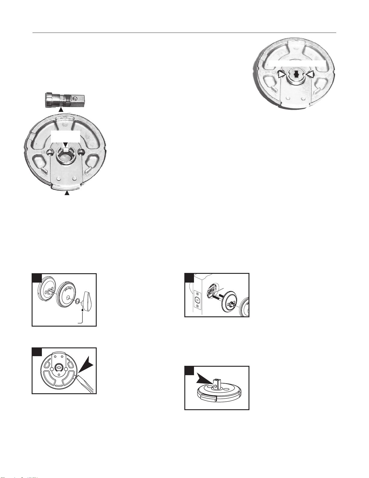
The NightWatch
®
mechanism consists of a simple mechanical deadbolt within the
thumb turn mechanism. The inside view of the thumb turn assembly here displays
the interlocking features. The spindle of the thumb turn has two depressions cast into
it and those depressions match two projections from the mounting plate when the
spindle is turned 90° to extend the bolt.
The movable button on the bottom of the mounting
plate can be pressed upward, and that allows the
thumb piece to be pulled outward and engage the
interlocking features. Shown (left) is a side view of the
spindle and mounting plate. Note the spindle deadlock
and the groove in the spindle.
The button at the bottom of the mounting plate raises the spindle deadlock out of the groove
in the spindle and allows it to be pulled outward. When it is pulled outward the two parts
interlock and prevent the thumb turn from being turned at all unless it is first pushed inward.
Because the cylinder tailpiece also enters the spindle, when the spindle is immobilized, the
tailpiece is too, and the cylinder cannot be used to operate the lock.
In the combination deadbolt, the dial mechanism is connected to a cam that turns the
tailpiece, and this also is rendered inoperable.
The NightWatch
®
function is only available in single cylinder deadbolts and combination deadbolts.
5
NightWatch
®
Function Grade 2 Residential
GROOVE
BUTTON
SPINDLE
DEADLOCK
INTERLOCKING AREA
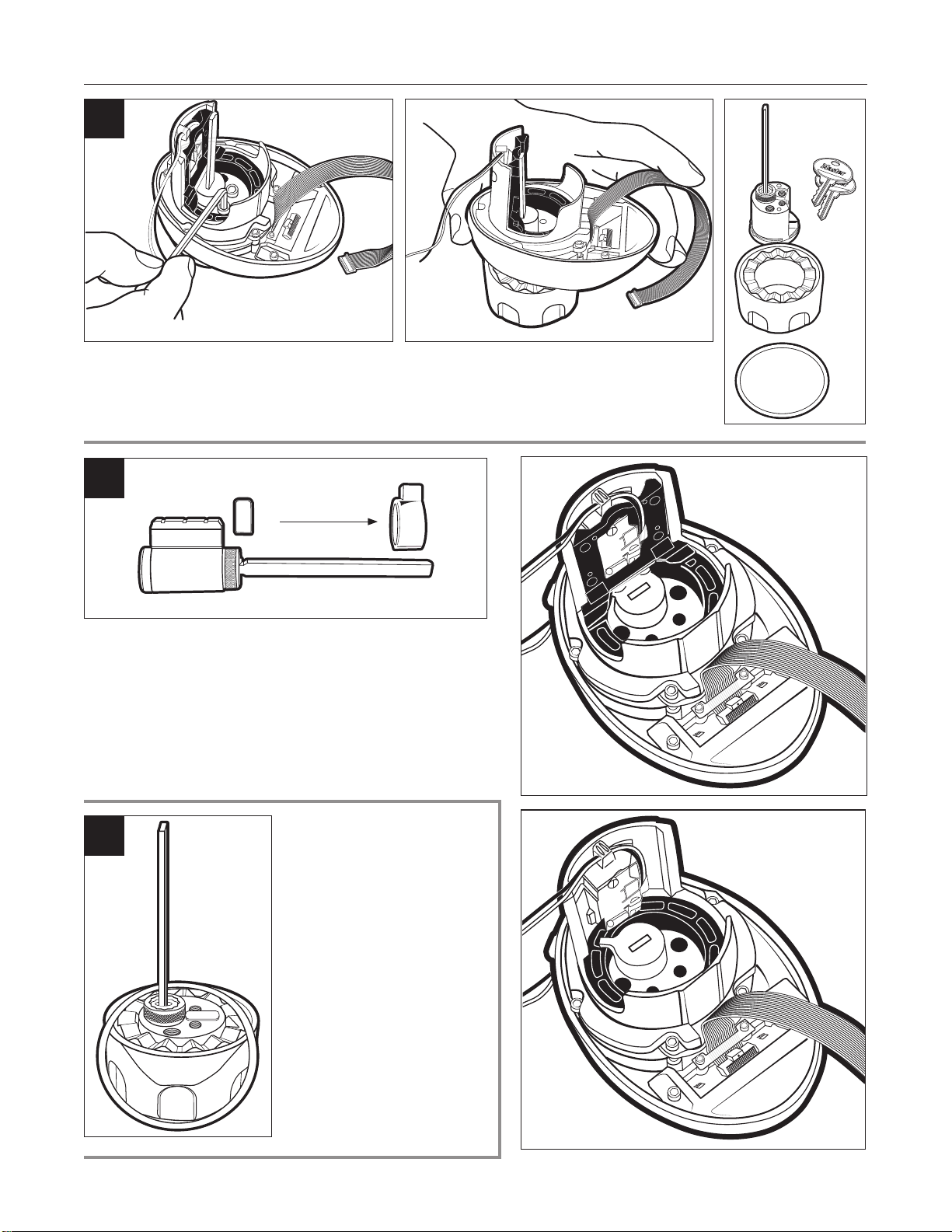
First, use the Allen wrench
provided in the hardware
package to remove thumb turn,
washer and separate rose from
rose plate. (see below)
To separate the rose plate
from the base, locate the
notch on the back side of
the base (the cover edge
extends above the base in
the notch area) and use
a screwdriver to apply
pressure to the edge of the rose cover separating it
from the base.
Install interior lever assembly — NightWatch deadbolt
Torque Blade
Torque Blade
Torque Blade
Torque Blade
To install plate, align torque
blade with turn piece
assembly, insert screws
through plate, through latch
and into the threaded holes in
the exterior housing. Tighten
screws. Snap rose onto rose plate. Attach thumb turn (see
below) and tighten set screw with Allen wrench.
When you reattach the thumb
turn, be sure that the recess in
the spindle is pointing down.
The set screw projects into this
recess when tightened.
1
2
3
4
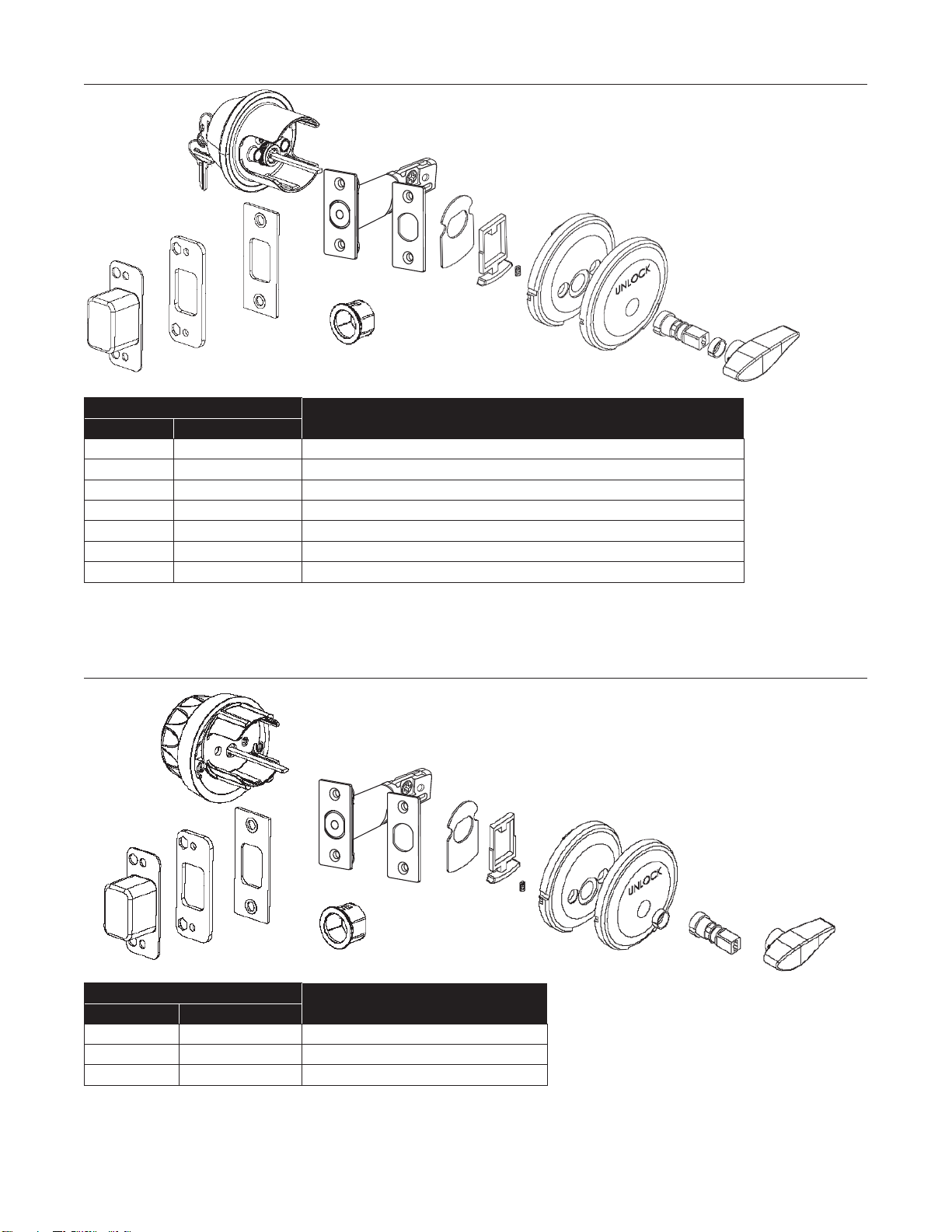
Standard NightWatch
®
Deadbolt with BumpStop
®
Grade 2 Residential
Combination NightWatch
®
Deadbolt Grade 2 Residential
6
Part Number
Product Description
Retail Boxed
DSRN0603P DSNRN0603PKA4
NightWatch, Single Cylinder, Polished Brass with BumpStop
®
DSNRN0605 DSNRN0605KA4
NightWatch, Single Cylinder, Antique Brass with BumpStop
®
DSNRN0615 DSNRN0615KA4
NightWatch, Single Cylinder, Satin Nickel with BumpStop
®
DSRNSD03PD045
NightWatch, Single Cylinder (Schlage C Keyway), Polished Brass with BumpStop
®
DSRNSD05D045
NightWatch, Single Cylinder (Schlage C Keyway), Antique Brass with BumpStop
®
DSRNSD15D045
NightWatch, Single Cylinder (Schlage C Keyway), Satin NIckel with BumpStop
®
DSRNSD12PD045
NightWatch, Single Cylinder (Schlage C Keyway), Aged Bronze with BumpStop
®
Part Number
Product Description
Retail Boxed
DSRN1003P DSNRN1003PBOX
NightWatch, Single Cylinder, Polished Brass
DSRN1005 DSNRN1005BOX
NightWatch, Single Cylinder, Antique Brass
DSRN1015 DSNRN1015BOX
NightWatch, Single Cylinder, Satin Nickel
7
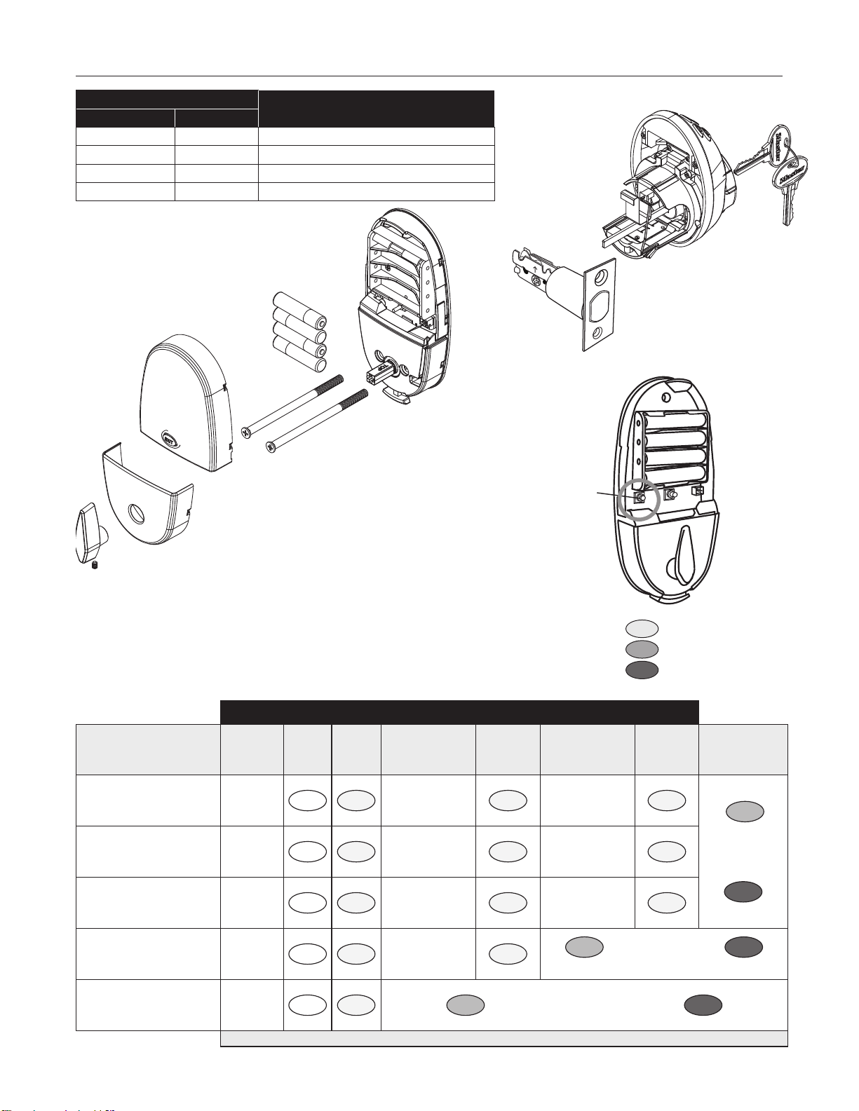
Electronic Keypad NightWatch
®
Deadbolt
Grade 2 Residential
UP
Part Number
Product Description
Retail Boxed
DSKP0603PD DSKP0603P
NightWatch, Electronic Keypad, Polished Brass
DSKP0605D DSKP0605
NightWatch, Electronic Keypad, Antique Brass
DSKP0615D DSKP0615
NightWatch, Electronic Keypad, Satin NIckel
DSKP0612PD DSKP0612P
NightWatch, Electronic Keypad, Aged Bronze
Steps > 2a 2b 2c 2d 2e 2f 2g
Function
Enter
Admin Code
(from page 2 of
User Guide)
Press
Function
Button
Press
Enter Enter Press Enter Data Confirmaton Press Enter
Programming
Completed
Add a User Code Admin Code
1-2
ENTER
New 4 to 10 digit User
Code
ENTER
New 4 to 10 digit User
Code
ENTER
ENTER
GREEN light is good
RED light,
restart at step 1
ENTER
Remove a User Code Admin Code
1-2
ENTER
User Code to be
removed
ENTER
User Code to be
removed
ENTER
Change Admin Code Admin Code
1-2
ENTER
New 6 digit Admin
Code
ENTER
New 6 digit Admin
Code
ENTER
Delete All User Codes Admin Code
1-2
ENTER
Current Admin Code
ENTER
ENTER
ENTER
GREEN light is good / RED light, restart at step 1
Deactivate/Reactivate
All user codes
Admin Code
1-2
ENTER ENTER
GREEN light is good / RED light, restart at step 1
ENTER
We recommend confirming changes by testing code after programming is complete
ENTER
(Blue Light)
ENTER
(Green Light)
ENTER
(Red Light)
Keypad Deadbolt – Quick Reference for Programming Function
Step 1 Remove battery cover – Press and hold PROGRAM button until blue light flashes.
Step 2 Enter the data in the row below based on what you want to do.
PROGRAM
EXIT
MOTOR
PROGRAM
EXIT
MOTOR
EXIT
Program
Button
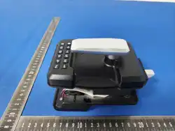
The cylinder housing is mounted via two screws in the exterior housing.
These screws have a thread locking substance on them. You will need to use the longer side of your hex
wrench to loosen them. They are around 7/8" long and use a 9/64" hex. With the screws removed, lift the
main housing to separate it from the trim.
Place the wave washer on the
trim before mounting to the
housing. The next step is to feed
the tailpiece through the slot in the
clutch cam and then tighten the
screws to reassemble.
Looking at the tailpiece orientation
from the back of the housing, it
should be horizontal for mounting
on a Right Hand door and vertical
for a Left Hand door. Do not
forget to pull the cable and wiring
harness excess to the inside of
the door when remounting. If not
pulled there is a potential for the
wiring to prevent free movement
of the clutch.
The cylinder bible has a spacer on the end. There is also a wave
washer between the trim and the housing. Any original brand cylinder
that has the same footprint can be used in place of this cylinder, just
be sure to use the spacer and tailpiece from this cylinder.
Remove the black Clutch from the external housing to reveal the cam
slot in the tailpiece activation mechanism. Put the clutch cam in place
and replace the clutch.
8
Electronic Keypad NightWatch
®
Deadbolt Rekeying
Grade 2 Residential
1
2
IBA-5
Clutch Cam
3
Deadbolt Information Grade 2 Residential
9
To change latch faces:
1. Use a flat screwdriver to separate the face plate.
2. Snap selected latch face onto back plate.
For drive-in installation:
1. Put the round face plate into
latchbolt as illustrated.
2. Press the cover plate to
lock in with latch and round
face plate.
3. Push the floating sleeve
forward until it is positioned
at the latch.
Attach the latch face that matches the mortise in the edge of your door
Attach the latch face that matches the mortise in the edge of your door
To change latch faces:
1. Use a flat screwdriver to separate the face plate.
2. Snap selected latch face onto back plate.
For drive-in installation:
1. Put the round face plate into latchbolt as
illustrated.
2. Press the cover plate to
lock in with latch and
round face plate.
3. Push the floating sleeve forward until it
is positioned at the latch.
Back Plate
Cover Plate
Floating Sleeve
Round Face Plate
Drive-In Latch
Floating Sleeve
Face Plate
Attach the latch face that matches the mortise in the edge of your door
To change latch faces:
1. Use a flat screwdriver to separate the face plate.
2. Snap selected latch face onto back plate.
For drive-in installation:
1. Put the round face plate into latchbolt as
illustrated.
2. Press the cover plate to
lock in with latch and
round face plate.
3. Push the floating sleeve forward until it
is positioned at the latch.
Back Plate
Cover
Plate
Floating Sleeve
Round Face Plate
Drive-In Latch
Floating Sleeve
Face Plate
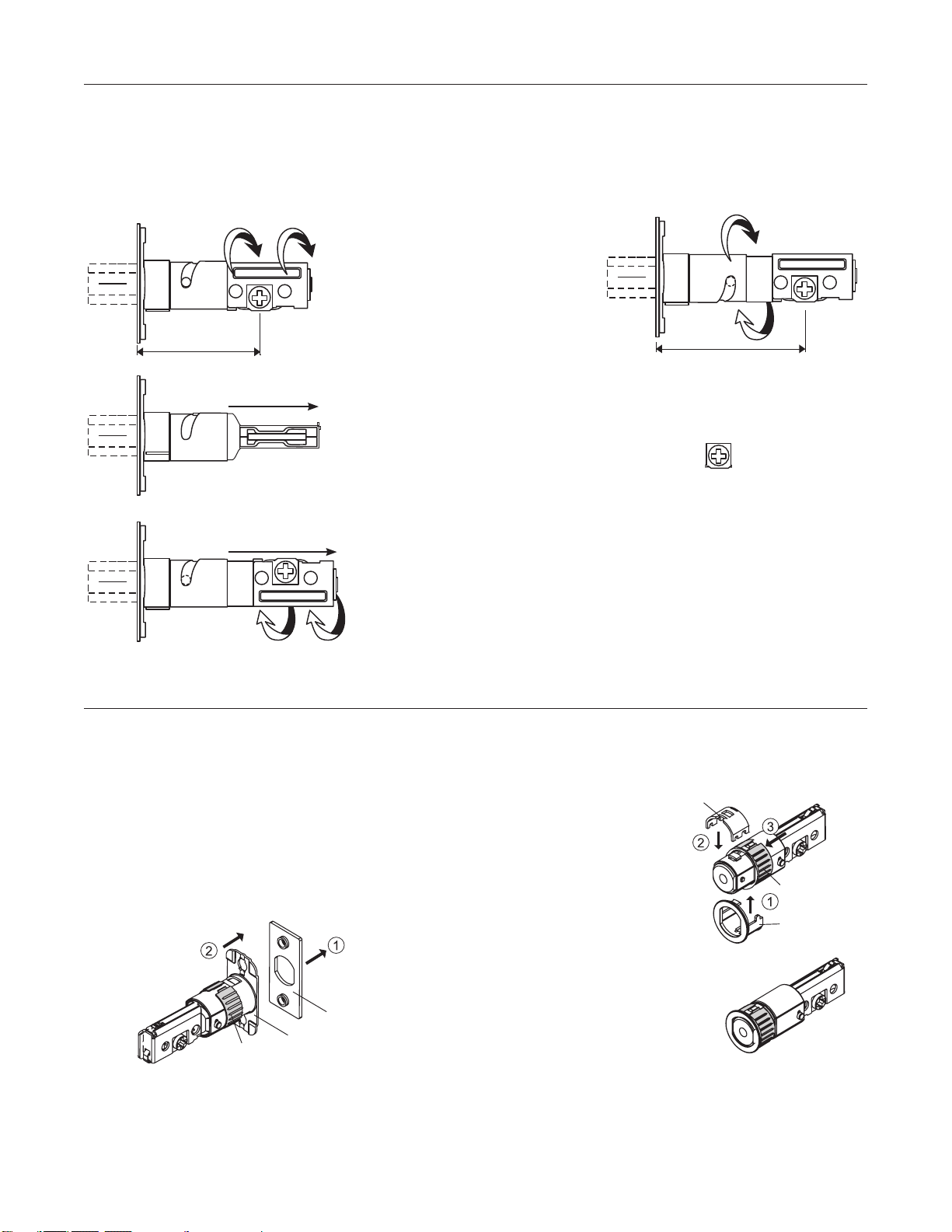
The bolt has changeable face plates to allow square corners, radiused corners or a drive-in face plate.
The deadbolt is available with a single or double cylinder function and may use any of the Master Lock Door Lock type
BumpStop
®
cylinders, a Kaba Lori 1599 cylinder or any other ‘size compatible’ cylinder. The bolt has an adjustable backset
for 2 3/8" or 2 3/4".
To change backset:
Changing your backset is as
simple as gripping and turning
the back portion of the latch.
Turn clockwise to extend to
2-3/4" or counter-clockwise to
return to 2-3/8". As the back
rotates, it will 'spiral' in or out,
as the mechanism follows the
machined groove.
When extending to 2-3/4", be sure to
flip the entire latch assembly before
placing it in the door. The tailpiece
receiver hole (
2-3/8"
60mm
2-3/4"
70mm
)should always
be postioned at the bottom of the
assembly.
Adjust the latch to match the backset dimension on your door
Combination NightWatch
®
Grade 2 Residential
2-3/8"
60mm
2-3/4"
70mm
2-3/8"
60mm
2-3/4"
70mm
To change from a square to radiused corner face plate, pry off the existing face plate and then attach the new one. Face
plates have a ferrule that is slightly swaged to hold it in place. Use a small screwdriver or chisel to make prying easier, then
swage the new face plate in place.
If changing to a drive-in bolt, pry off the existing face plate. Then:
•Spreadtheoatingsleeveandmoveitawayfromthebackplate
•Pushinonthebackplateandturncounter-clockwise,thenpulloff
•Placetheroundfaceplateonthebolt
•Movetheoatingsleeveforward
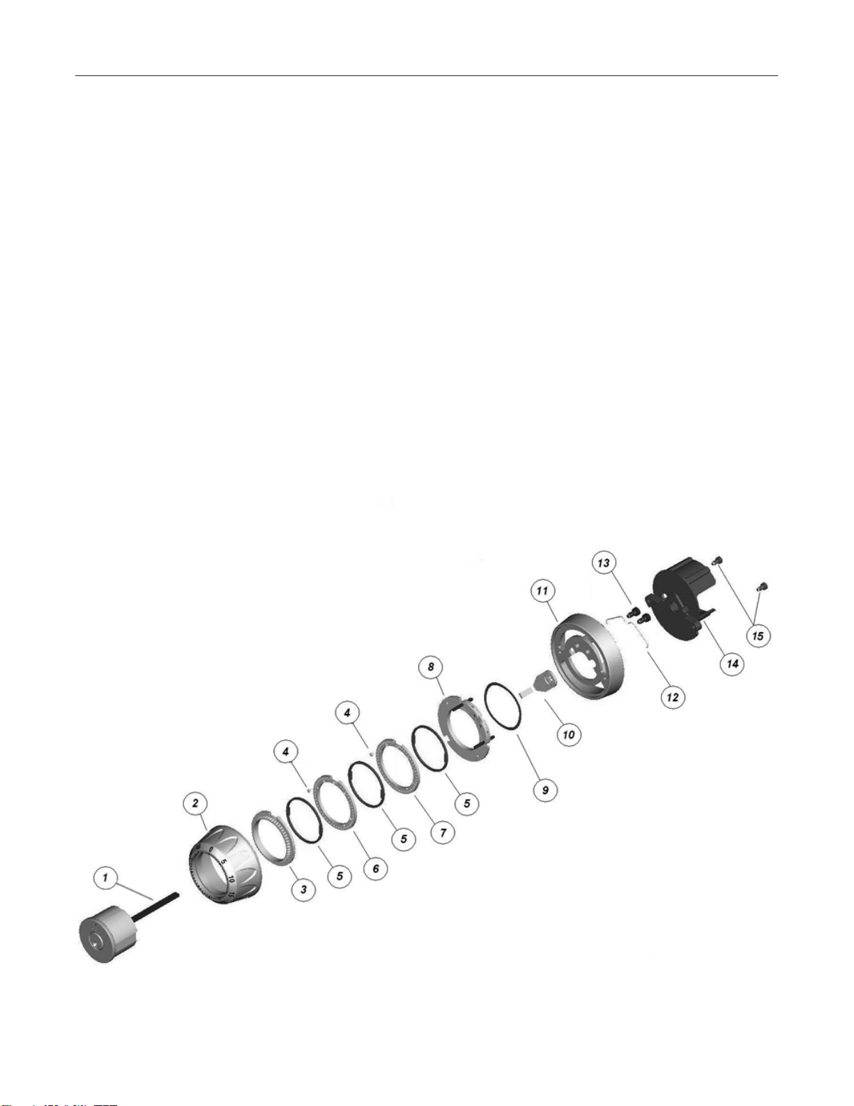
Below is the exploded view of the cylinder/dial assembly. You will find instructions for decoding an existing combination and
for encoding a new combination immediately after the exploded view. Two parts below are critical to lock operation: Item 4,
the fly- PKG50994 and Item 12, the disruptor spring – PKG50998. Component parts are available.
Deadbolt Information (continued) Grade 2 Residential
10
1. Cylinder Tailpiece – PKG 50975
2. Dial
3. Drive Cam
4. Fly – PKG50994
5. Anti-friction Spacer –PKG 50993
6. Combination Disk 2 – PKG 50991
7. Combination Disk 3 – PKG 50992
8. Dual Fence Ring –PKG 57385
9. Wave Washer – PKG 50996
10. Cam –PKG 51000
11. Trim Hub
12. Disrupter Spring – PKG 50998
13. Dial Ring Screws – PKG 51003
14. Baffle Plate
15. Baffle Plate Screws –PKG 57384
Because of the fixed fly design, a certain amount of calculation can be required when decoding or encoding. Master Lock
also offers a software program that will do the calculations for you at:
http://www.masterlock.com/combocalc.msi
This software has been tested on Windows
®
XP and Vista
®
and runs correctly. It may be compatible with some earlier
versions of Windows
®
but has not been tested. To complete the software installation, you must have the free Microsoft
program ‘.net framework’ installed.
The following instructions also are included in a help file in the software.
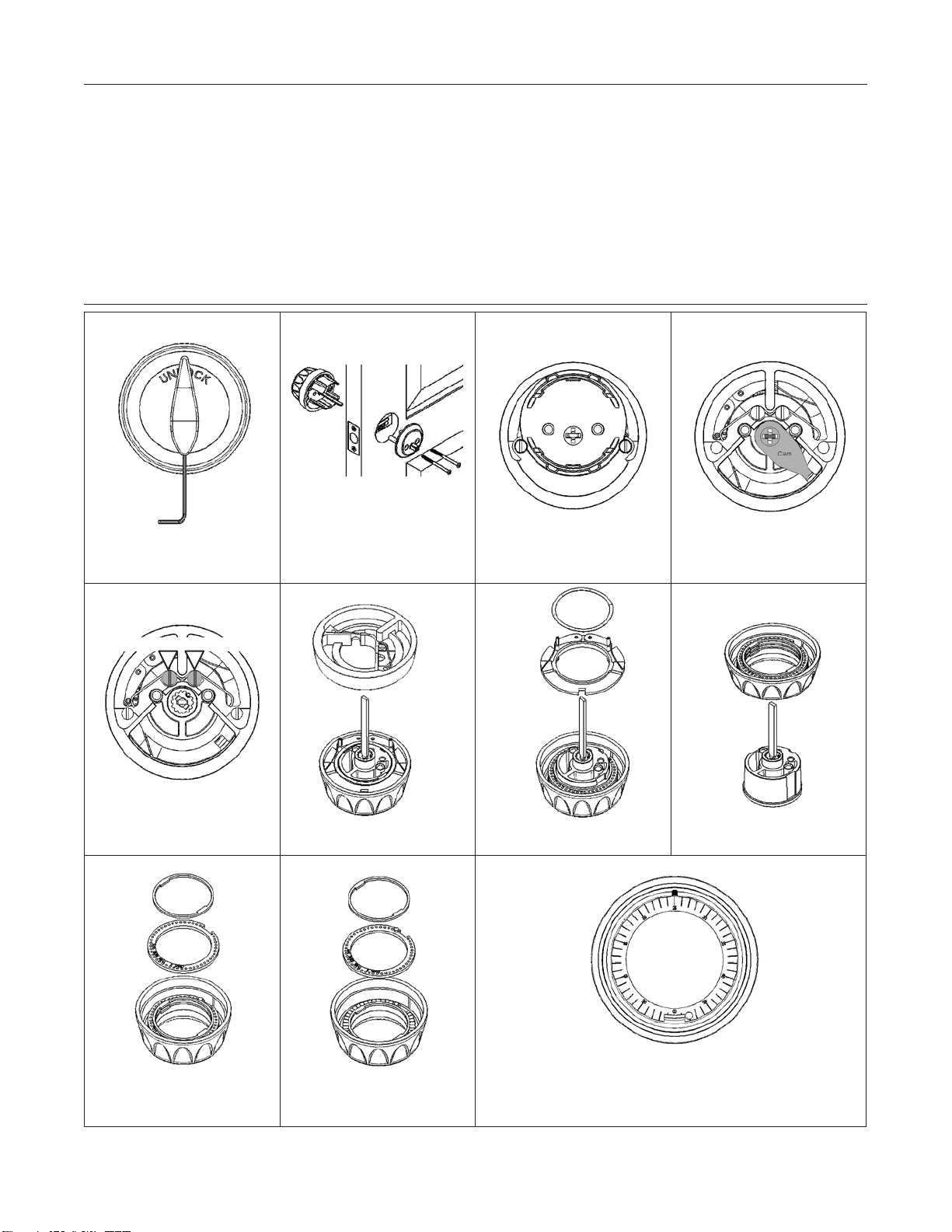
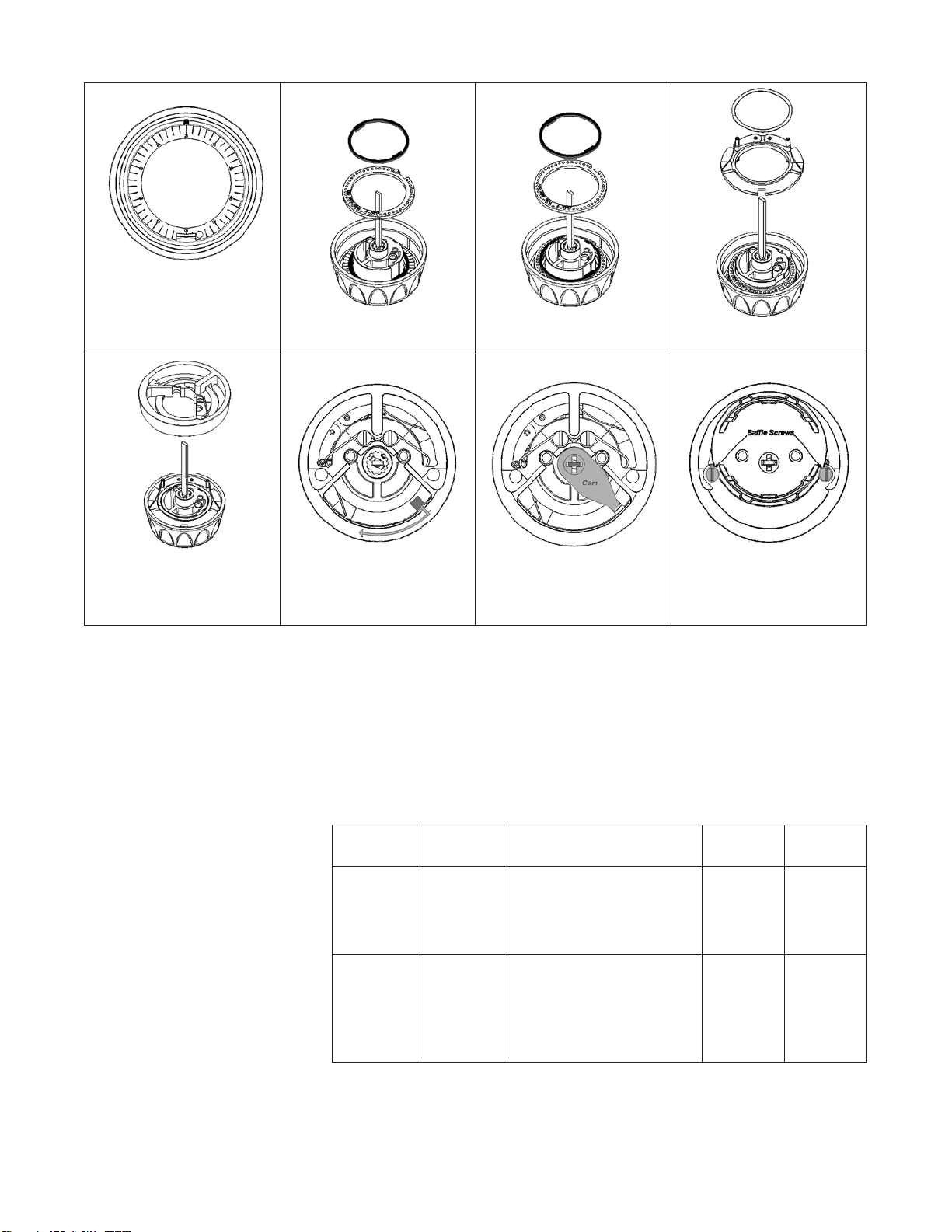
11
Use a 1/16" hex wrench to
remove thumb turn
Remove inside trim and
dismount lock from door
Loosen two screws and remove
baffle plate from dial assembly
Lift cam and remove from
cylinder tailpiece
Loosen the two dial ring/
cylinder mounting screws
Remove dial ring with disrupter
spring
Remove the wave washer and
the dual fence ring
GENTLY lift dial ring from
cylinder
Remove a spacer washer and
disk 3; DO NOT disturb disk 1
Remove a spacer washer and
disk 2; DO NOT disturb disk 1
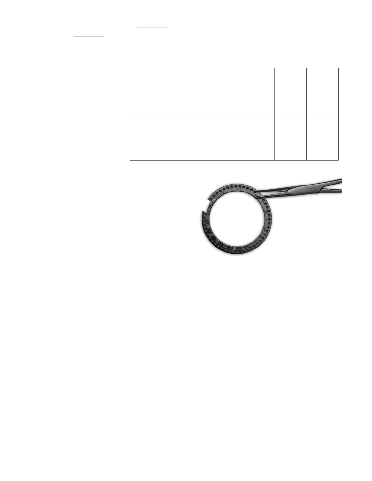
A groove is cast into the interior of the dial ring. Determine the
number aligned with that groove and record it in the ‘Set to
Disk 1’ column of the worksheet
Deadbolt Information (continued) Grade 2 Residential
Decode
CyliNDeR mOuNtiNg SCRewS
12
Deadbolt Information (continued) Grade 2 Residential
Determine the numerical location of the fly in disks 2 and 3 and record them in the ‘Set to’ column in the worksheet. Note
that the setting of the first disk is the third number of the combination.
Simple mathematics are required to figure out the first and second combination numbers. Next, we will calculate the
combination for the disk locations shown.
To determine the second number of the existing combination, you must add settings one and two plus 1; in this case, 14 +
25 + 1 = 40. Because the total isn’t 50 or more, you don’t need to go further. If the total had been 50 or more, you would
need to subtract 50 until the answer is less than 50. Write the answer in the combination 2 box.
For the first number of the combination, add the set to column to get a total, e.g. 14 + 25 + 17 + 6 = 62. Because the total
is 50 or more, subtract 50 until the answer is less than 50. 62 – 50 = 12. That is the first combination number and may be
written into combination box 1.
DECODING
Disk Set to Formula Combination
The disk that contacts the dial
1
14
Combination = where set
14
3
The middle disk
2
25
Add 1 & 2 plus 1, subtract 50
until answer is less than 50
2
The disk that comes out first
3
17
Subtract 50 from Total until
answer is less than 50
1
Add 6
Total =
DECODING
Disk Set to Formula Combination
The disk that contacts the dial
1
14
Combination = where set
14
3
The middle disk
2
25
Add 1 & 2 plus 1, subtract 50
until answer is less than 50
40
2
The disk that comes out first
3
17
Subtract 50 from Total until
answer is less than 50
1
Add 6
Total =
DECODING
Disk Set to Formula Combination
The disk that contacts the dial
1
14
Combination = where set
14
3
The middle disk
2
25
Add 1 & 2 plus 1, subtract 50
until answer is less than 50
40
2
The disk that comes out first
3
17
Subtract 50 from Total until
answer is less than 50
12
1
Add 6
Total =
62
Unlike a safe, this combination is applied three times clockwise to 12, two times counterclockwise to 40 and one time
clockwise to 14. At that point, you should feel the fence enter the gate and then may turn the dial in the direction required to
throw or retract the bolt.
Encoding a lock to a new combination follows the same disassembly and reassembly steps but uses different calculations to
determine fly locations on the various disks. As you can see here, the worksheet for encoding is different also.
Use the following steps to reassemble the lock.
Ensure that drive disk 1 has not
been moved from the decoded
position and place it over the
cylinder
Install a spacer washer, disk 2
and another spacer washer
Install disk 3 and another
spacer washer
Install fence ring and wave
washer
Install dial ring, making sure
wave washer is centered and
disrupter spring is correctly
positioned
Set handing by moving cam
slot to bolt edge side and make
tailpiece horizontal Reinstall cam
Attach baffle plate and
mount lock on door. Try the
combination to lock and unlock
to verify the decoding
ENCODING
Disk Set to Formula Combination
The disk that contacts the dial
1
Align with Dial Index
3
The middle disk
2
Second number minus 1.
Then subtract third number
if less than zero, add 50 until
between 0 and 49.
2
The disk that comes out first
3
Add set positions for disks
1 and 2 plus 6. Subtract
that from combination 1. If
less than zero, add 50 until
between zero and 49.
1
13

ENCODING
Disk Set to Formula Combination
The disk that contacts the dial
1
38
Align with Dial Index
38
3
The middle disk
2
Second number minus 1.
Then subtract third number
if less than zero, add 50 until
between 0 and 49.
25
2
The disk that comes out first
3
Add set positions for disks
1 and 2 plus 6. Subtract
that from combination 1. If
less than zero, add 50 until
between zero and 49.
18
1
ENCODING
Disk Set to Formula Combination
The disk that contacts the dial
1
38
Align with Dial Index
38
3
The middle disk
2
36
Second number minus 1.
Then subtract third number
if less than zero, add 50 until
between 0 and 49.
25
2
The disk that comes out first
3
Add set positions for disks
1 and 2 plus 6. Subtract
that from combination 1. If
less than zero, add 50 until
between zero and 49.
18
1
There are some mechanical limitations that result in forbidden combinations:
• Disk2mustbeseton2thru47aspositions0,1,48and49donotexist
• Disk3cannotbeseton0,1or49asthosepositionsdonotexist
The example below will calculate the drive disk and fly locations for a new combination of 18-25-38. The first step is to
write the combination into the worksheet and automatically set the drive disk to the third number.
To calculate the fly location for disk 2 we must take the second number of the combination and subtract 1. For the example,
that is 25 – 1 = 24. Then the third number also should be subtracted from that answer: 24 – 38 = -14. Because that answer
isn’t between 0 and 49, we must add 50 until it is: -14 + 50 = 36. The answer is the location of the fly on disk 2 and should
be written in the worksheet.
14
15
The next step is physical relocation of disk 1 so that the number
38 is aligned with the groove cast into the dial ring. Next the flys
must be moved on disks 2 and 3.
That can be accomplished by firmly gripping the fly and pulling it
from the disk while rocking it forward and back. The fly is pressed
into place and should not be hard to relocate. Place it in the newly
determined location and then press into place.
Use the reassembly directions given earlier to reassemble the lock
and remount on the door. Operate the new combination with the
door open to throw and retract the bolt.
Rekeying
Rekeying the key operated cylinder may be accomplished using a standard pinning kit and the BumpStop
®
procedures
related on pages 2, 4 and 33. Rekeying the cylinder only requires removal of the baffle plate and cam to access the
screw-on retainer cap for the plug. Remove the cap, cap pin and spring, then use a follower to remove the plug.
Rekey as desired and then reassemble. Always check the bible of the cylinder to ensure that there aren’t master pins being
left in the cylinder when rekeying and to reposition the BumpStop
®
pin if your new combination doesn’t have a compatible
bitting in the same chamber as the last combination.
The Master Lock software program available for locksmiths will do the encoding and decoding calculations for you. It is not
recommended for the do-it-yourself end user but can be a valuable tool for the locksmith. For some computers, you may
need to get a free upgrade from Microsoft called ‘.net framework’ to be able to install the software. Enter the link below on
your browser to access the program for installation.
http://www.masterlock.com/combocalc.msi
ENCODING
Disk Set to Formula Combination
The disk that contacts the dial
1
38
Align with Dial Index
38
3
The middle disk
2
36
Second number minus 1.
Then subtract third number
if less than zero, add 50 until
between 0 and 49.
25
2
The disk that comes out first
3
38
Add set positions for disks
1 and 2 plus 6. Subtract
that from combination 1. If
less than zero, add 50 until
between zero and 49.
18
1
The disk 3 calculations require adding the set positions for disk 1 and 2 plus 6, e.g. 38 + 36 + 6 = 80. That answer must be
subtracted from combination number 1: 18 – 80 = -62. Because the answer is not between 0 and 49, you must add 50 until
it is: -62 + 50 = -12; -12 + 50 = 38. Write the answer in the worksheet.

16
Grade 2 Commercial
The Grade 2 Commercial products use a universal cylinder similar to a Kaba Lori 1599. Extra cylinders may be ordered and
used for retrofit when a customer’s existing locks need to be upgraded with our BumpStop
®
advanced cylinder technology.
Ordering cylinders is a simple process using the DL part number map below.
For BumpStop
®
pinning information, consult the table and information on pages 2, 3 and 4. All of these cylinders may be
keyed with standard bottom pins found in aftermarket pinning kits for .115" diameter pin tumblers.
DL045KD
Door Hardware Cylinder Keying Specification
w/Cap Retainer KD –Keyed Different
KA –Keyed Alike
Keyway KZ –Zero Bitted
KDMK –KD Master Keyed
KAMK–KA Masker keyed
UN –Uncombinated**
Manufacturer’s Brand Name
Arrow
®
10
Corbin
®
59A1-201
Corbin
®
60 29
Corbin
®
Russwin
®
L4 07
Falcon
®
1573, 1577* 14
Harloc
®
SE-1*02
Kwikset
®
*12
Lockwood
®
08
Lori
®
L200* 02
Lori
®
Locksmith 80 80
Loricentric
®
90 90
Master
®
/Dexter
®
67* 32
Russwin
®
981/852 11
Russwin
®
D1 30
Sargent
®
LA-LC* 36
Sargent
®
RA-RC* 70
Sargent
®
S* 02
Sargent
®
U* 02
Schlage
®
C04
Schlage
®
E34
Schlage
®
P28
Segal
®
9.265 27
Weiser
®
*13
Weslock
®
33
Yale
®
803
Yale
®
GA 15
Master Lock
®
200WP
EDGE
®
System
(Available with 4 or 6 pins only)
Number of pins
4 – four**
5 – five
6 – six
* Indicates a composite keyway that accepts more than one key section. Example: Keyway 02 accepts the
Sargent
®
S, Sargent
®
U, and Lori
®
L200 keys.
** Exclusively available for the Master Lock EDGE
™
Key Control System only.
All marks are registered trademarks of their respective owners
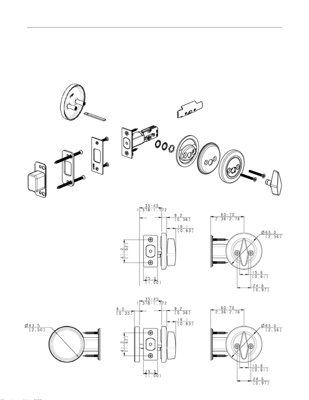
Communicating Door Deadbolt Grade 2 Commercial
Single-Sided/Communicating Door
FuNCtiON: Handle or turn piece on one side to throw or retract bolt; no means of operation on opposite side.
DSC0532D Brushed Chrome
This is a combination unit designed for application to doors with a full crossbore or for doors where the crossbore is only
visible on the inside. The adjustable backset bolt and reinforced strike are standard equipment.
OR
17
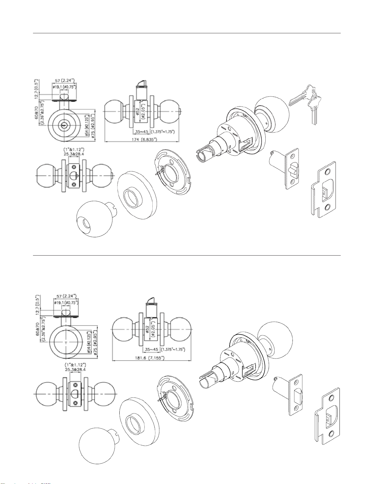
Entry Knobset with BumpStop
®
Grade 2 Commercial
FuNCtiON: Inside handle push button locks the outside handle. Unlock outside handle with a key or by turning inside handle.
BlC0132DKA4 Brushed Chrome
The Entry lockset may use any of the Master Lock DL type cylinders, a Kaba Lori 1539 cylinder or any other ‘size compatible’ cylinder.
The exterior rose should be adjusted to accommodate different door thicknesses of 1 3/8" to 1 3/4".
Passage Knobset Grade 2 Commercial
FuNCtiON: Inside and outside handles always unlocked; turning either retracts latch. No keys required.
BlC0432D Brushed Chrome
The exterior rose should be adjusted to accommodate different door thicknesses of 1 3/8" to 1 3/4".
18
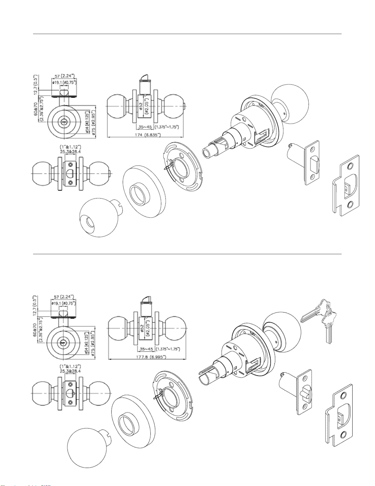
Privacy Knobset Grade 2 Commercial
FuNCtiON: Inside handle push button locks outside handle. Emergency release in outside handle. Closing the door or turning inside
handle releases the push button.
BlC0332D Brushed Chrome
The exterior rose should be adjusted to accommodate different door thicknesses of 1 3/8" to 1 3/4".
Classroom Knobset with BumpStop
®
Grade 2 Commercial
FuNCtiON: Inside always unlocked. Outside handle locked or unlocked by key.
BlC0932DKA4 Brushed Chrome
The exterior rose should be adjusted to accommodate different door thicknesses of 1 3/8" to 1 3/4" (Classroom US32D).
19
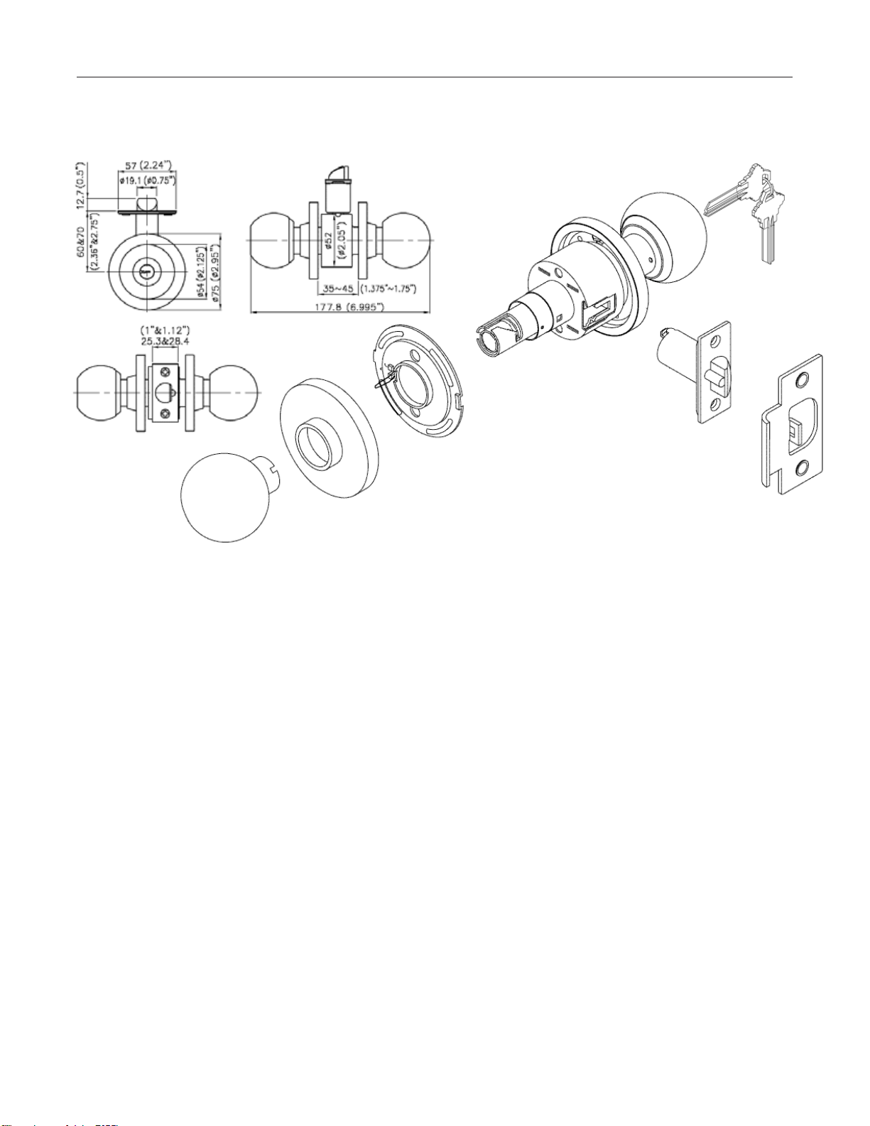
Storeroom Knobset Grade 2 Commercial
FuNCtiON: Inside always unlocked. Outside handle always locked. Latch retracted by turning key.
BlC0232DKA4
Brushed Chrome
The exterior rose should be adjusted to accommodate different door thicknesses of 1 3/8" to 1 3/4" (Storeroom US32D).
20
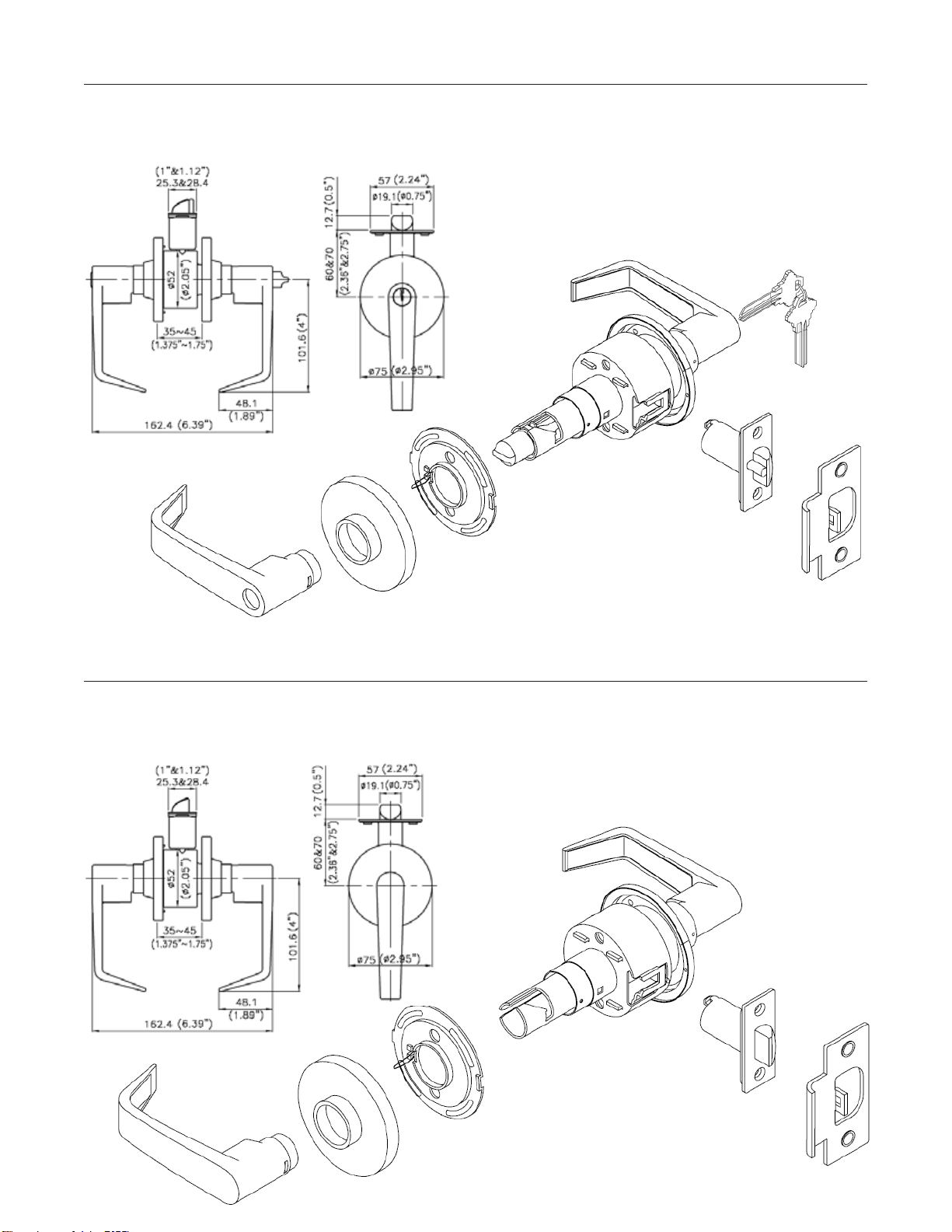
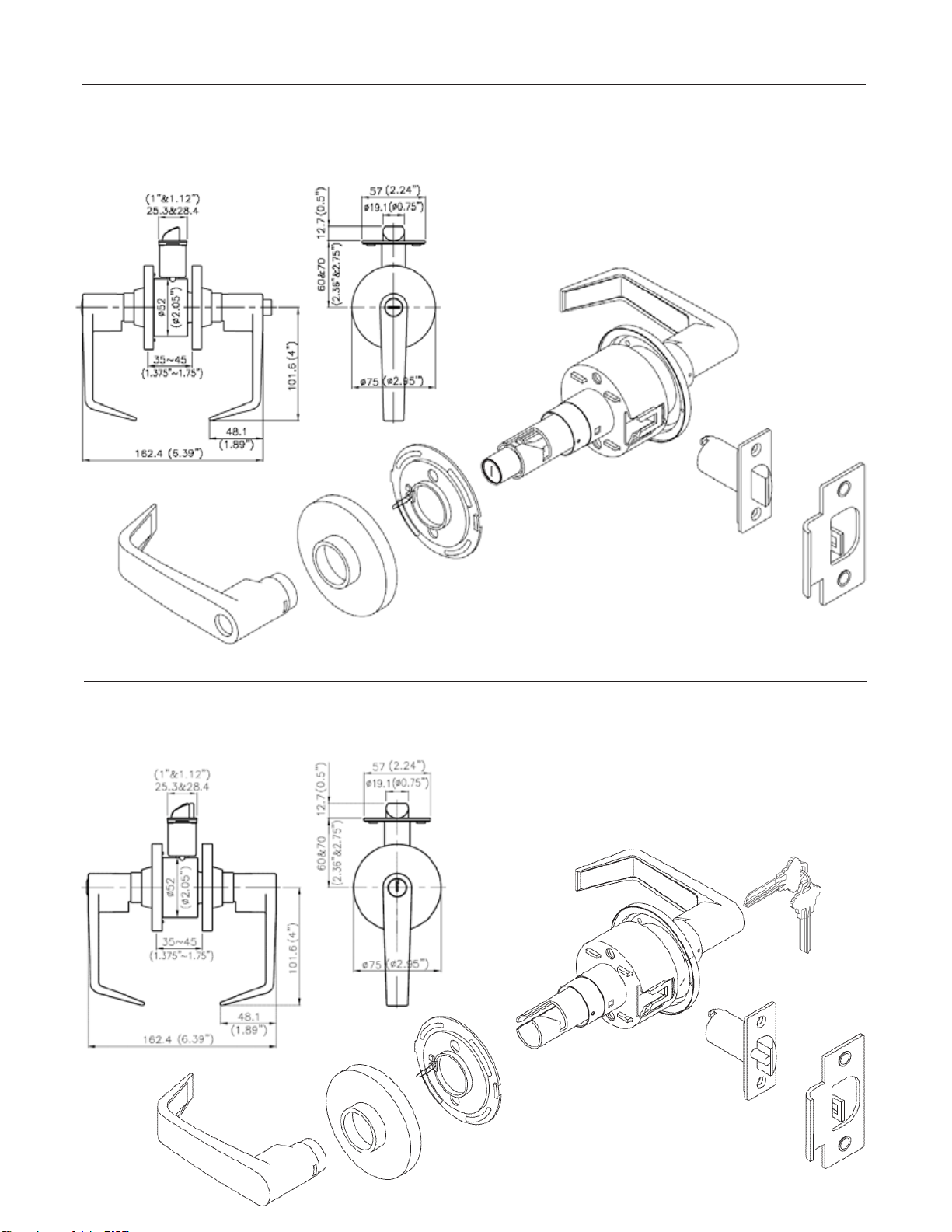
Entry Leverset with BumpStop
®
Grade 2 Commercial
FuNCtiON: Inside handle push button locks the outside handle. Unlock outside handle with a key or by turning inside handle.
SlC0126DKA4 Brushed Chrome
The exterior rose should be adjusted to accommodate different door thicknesses of 1 3/8" to 1 3/4".
Passage Leverset Grade 2 Commercial
FuNCtiON: Inside and outside handles always unlocked; turning either retracts latch. No keys required.
SlC0426D Brushed Chrome
The exterior rose should be adjusted to accommodate different door thicknesses of 1 3/8" to 1 3/4".
21
Classroom Leverset with BumpStop
®
Grade 2 Commercial
FuNCtiON: Inside always unlocked. Outside handle locked or unlocked by key.
SlC0926DKA4 Brushed Chrome
The exterior rose should be adjusted to accommodate different door thicknesses of 1 3/8" to 1 3/4".
22
Privacy Leverset Grade 2 Commercial
FuNCtiON: Inside handle push button locks outside handle. Emergency release in outside handle. Closing the door or turning inside
handle releases the push button.
SlC0326D Brushed Chrome
The exterior rose should be adjusted to accommodate different door thicknesses of 1 3/8" to 1 3/4".
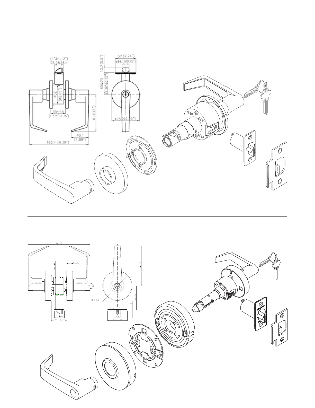
Storeroom Leverset with BumpStop
®
Grade 2 Commercial
FuNCtiON: Inside always unlocked. Outside handle always locked. Latch retracted by turning key.
SlC0226DKA4 Brushed Chrome
The exterior rose should be adjusted to accommodate different door thicknesses of 1 3/8" to 1 3/4".
23
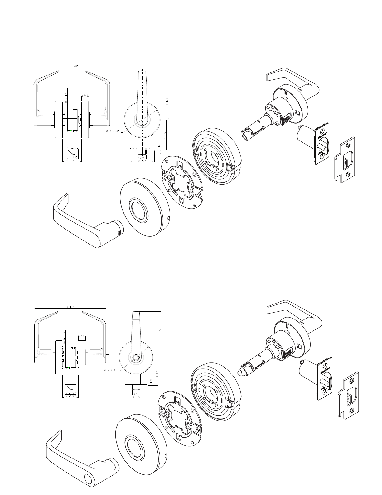
Heavy Duty Entry Leverset with BumpStop
®
Grade 2 Commercial
FuNCtiON: Inside handle turn button locks the outside handle. Unlock outside handle with a key or by turning inside handle.
SlCHKe26D Brushed Chrome
The exterior rose should be adjusted to accommodate different door thicknesses of 1 3/8" to 1 3/4".
24
Heavy Duty Privacy Leverset Grade 2 Commercial
FuNCtiON: Inside handle turn button locks outside handle. Emergency release in outside handle. Closing the door or turning inside
handle releases the push button.
SlCHPV26D Brushed Chrome
The exterior rose should be adjusted to accommodate different door thicknesses of 1 3/8" to 1 3/4".
Heavy Duty Passage Leverset Grade 2 Commercial
FuNCtiON: Inside and outside handles always unlocked; turning either retracts latch. No keys required.
SlCHPg26D Brushed Chrome
The exterior rose should be adjusted to accommodate different door thicknesses of 1 3/8" to 1 3/4".
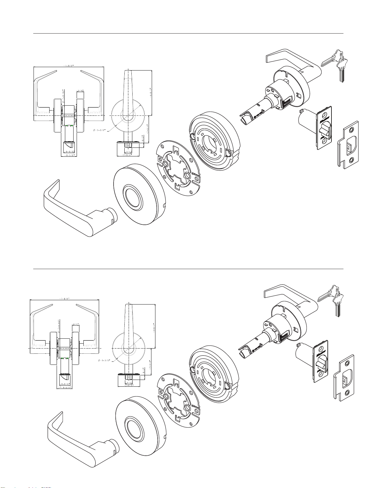
Heavy Duty Storeroom Leverset w/BumpStop
®
Grade 2 Commercial
FuNCtiON: Inside always unlocked. Outside handle locked or unlocked by key.
SlCHSR26D Brushed Chrome
The exterior rose should be adjusted to accommodate different door thicknesses of 1 3/8" to 1 3/4".
25
Heavy Duty Classroom Leverset w/BumpStop
®
Grade 2 Commercial
FuNCtiON: Inside always unlocked. Outside handle locked or unlocked by key.
SlCHCR26D Brushed Chrome
The exterior rose should be adjusted to accommodate different door thicknesses of 1 3/8" to 1 3/4".
26
Double Cylinder Deadbolt with BumpStop
®
Grade 2 Commercial
DSC0732DKA4 Brushed Chrome
Single Cylinder Deadbolt with BumpStop
®
Grade 2 Commercial
DSC0632DKA4 Brushed Chrome
Heavy Duty Single Cylinder Deadbolt w/ BumpStop
®
Grade 2 Commercial
DSCHSD32D Brushed Chrome
27
Heavy Duty Double Cylinder Deadbolt w/ BumpStop
®
Grade 2 Commercial
DSCHDD32D Brushed Chrome
2.50
1-3/8 – 2
[35,0 – 51,0]
[59,0]
ø2.56
[ø65.0]
ø2.00
[ø50,8]
ø2.00
[ø50.8]
ø2.56
[ø65,0]
2.50
[59,0]
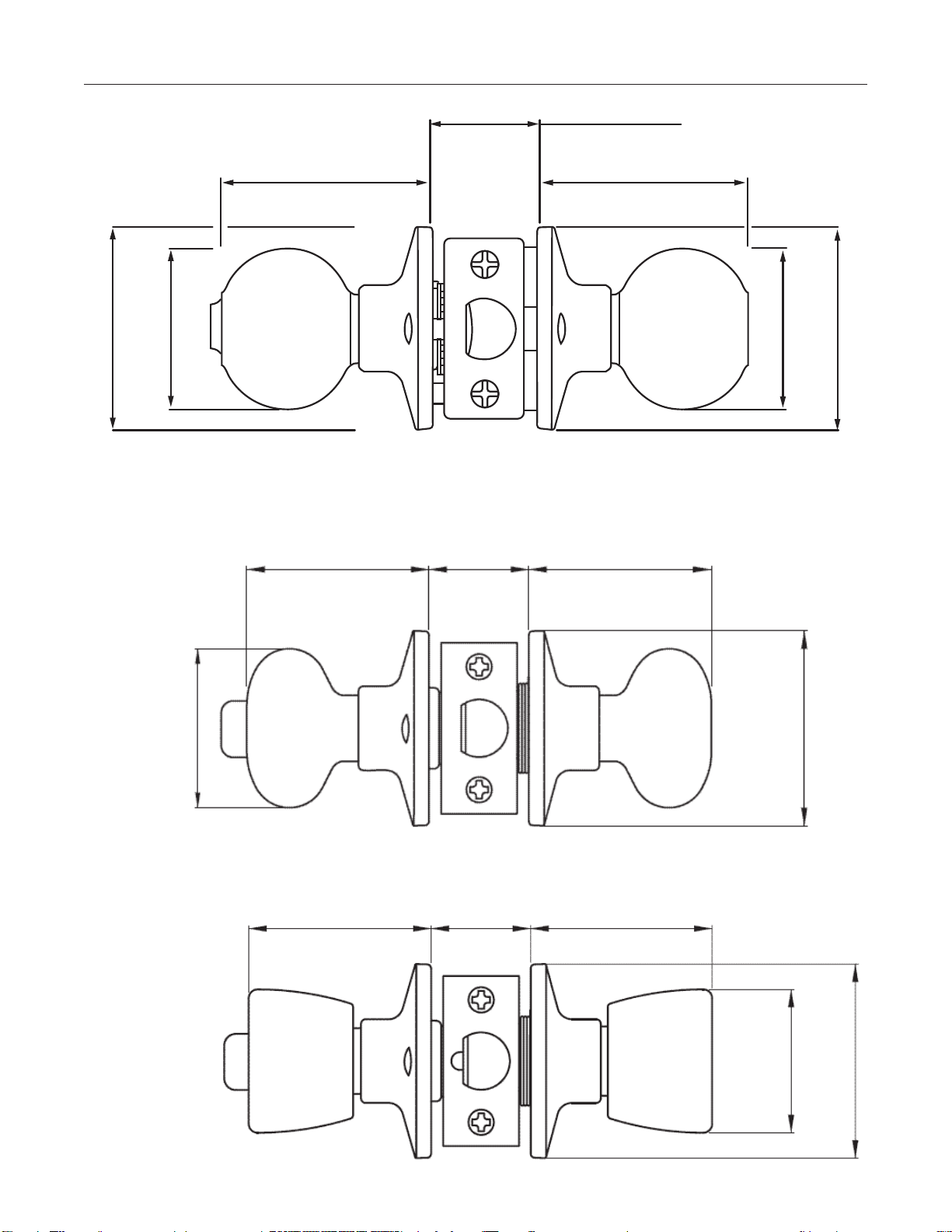
Knob Styles Grade 3 Residential
Ball Style
Biscuit Style
Tulip Style
28
2.39"
±0.08
(60.8)
±2.0
2/4"
±0.08
(61)
±2.0
2/4"
±0.08
(61)
±2.0
±0.02 ±0.5
ø2.08" (ø53.0)
±0.02 ±0.5
ø1.89" (ø48.0 )
±0.02 ±0.5
ø2.56" (ø65)
±0.02 ±0.5
ø2.56" (ø65)
2.39"
±0.08
(60.8)
±2.0
1.375" – 1.75"
(35-45)
1.375" – 1.75"
(35-45)
29
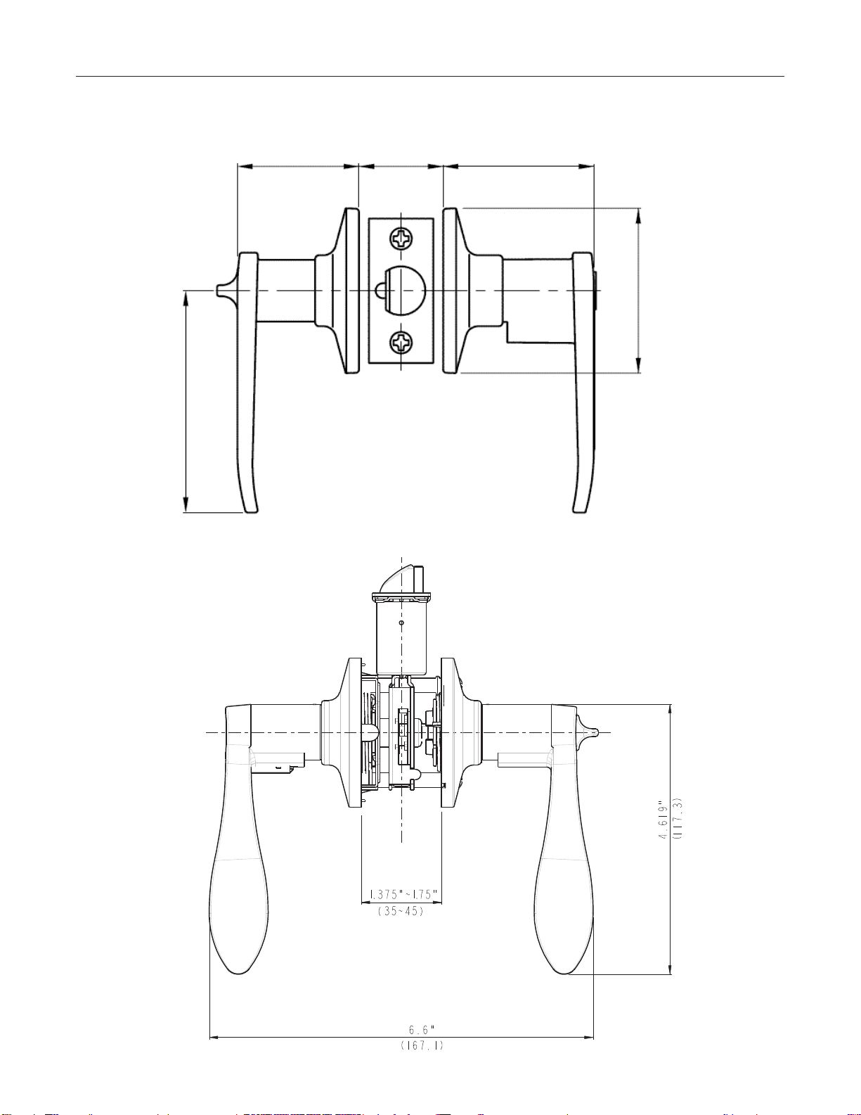
Wave Lever
Lever Styles Grade 3 Residential
Straight Lever
1.89"
(48.0)
3.465"
(88)
2.32"
(59.0)
30
Deadbolt and Handleset Styles Grade 3 Residential
Deadbolt – Single Cylinder
Handleset
Interior available in:
• BallKnob
• BiscuitKnob
• TulipKnob
• WaveLever
Deadbolt – Double Cylinder

31
Entry Knobset Grade 3 Residential
Biscuit Knob Shown
Part Number
Product Description
Retail Boxed
tuO0103 tuO0103KA4
Polished Brass Tulip Entrance
tuO0105 tuO0105KA4
Antique Brass Tulip Entrance
tuO0115 tuO0115KA4
Satin Nickel Tulip Entrance
BAO0103 BAO0103KA4
Polished Brass Ball Knob Entrance
BAO0105
N/A
Antique Brass Ball Knob Entrance
BAO0115 BAO0115K A4
Satin Nickel Ball Knob Entrance
BCO0103 BCO0103KA4
Polished Brass Biscuit Entrance
BCO0105 BCO0105KA4
Antique Brass Biscuit Entrance
BCO0115 BCO0115KA4
Satin Nickel Biscuit Entrance
BCO0112P BCO0112PKA4
Aged Bronze Biscuit Entrance
FuNCtiON: Turn button on inside handle locks or unlocks
outside and inside. Key in outside locks or unlocks. When locked,
handles are rigid. When unlocked, either will retract latch.
Passage Knobset Grade 3 Residential
Part Number
Product Description
Retail Boxed
tuO0403 tuO0403/t6P
Polished Brass Tulip Passage
tuO0405 tuO0405/t6P
Antique Brass Tulip Passage
tuO0415 tuO0415/t6P
Satin Nickel Tulip Passage
BAO0403 BAO0403/t6P
Polished Brass Ball Knob Passage
BAO0405
N/A
Antique Brass Ball Knob Passage
BAO0415 BAO0415/t6P
Satin Nickel Ball Knob Passage
BCO0403 BCO0403/t6P
Polished Brass Biscuit Passage
BCO0405 BCO0405/t6P
Antique Brass Biscuit Passage
BCO0415 BCO0415/t6P
Satin Nickel Biscuit Passage
BCO0412P BCO0412Pt6P
Aged Bronze Biscuit Passage
Ball Knob Shown
FuNCtiON: Inside and outside handles always unlocked;
turning either retracts latch. No keys required.
32
FuNCtiON: Key in outside locks or unlocks. When locked,
handle on outside is rigid. When unlocked will retract latch.
Inside handle always unlocked, turning retracts latch.
Storeroom Knobset Grade 3 Residential
Ball Knob Shown
Part Number
Product Description
Boxed
tuO0203KA4
Polished Brass Tulip Storeroom
tuO0215KA4
Satin Nickel Tulip Storeroom
BAO0203PKA4
Polished Brass Ball Storeroom
BAO0215PKA4
Satin Nickel Ball Storeroom
BCO0203KA4
Polished Brass Biscuit Storeroom
BCO0215KA4
Satin Nickel Biscuit Storeroom
BCO0212PKA4
Aged Bronze Biscuit Storeroom
FuNCtiON: Inside handle push button locks outside handle.
Emergency release in outside handle. Closing the door or turning
inside handle releases the push button.
Privacy Knobset Grade 3 Residential
Part Number
Product Description
Retail Boxed
tuO0303 tuO0303/t6P
Polished Brass Tulip Privacy
tuO0305 tuO0305/t6P
Antique Brass Tulip Privacy
tuO0315 tuO0315/t6P
Satin Nickel Tulip Privacy
BAO0303 BAO0303/t6P
Polished Brass Ball Knob Privacy
BAO0305
N/A
Antique Brass Ball Knob Privacy
BAO0315 BAO0315/t6P
Satin Nickel Ball Knob Privacy
BCO0303 BCO0303/t6P
Polished Brass Biscuit Privacy
BCO0305 BCO0305/t6P
Antique Brass Biscuit Privacy
BCO0315 BCO0315/t6P
Satin Nickel Biscuit Privacy
BCO0312P BCO0312P/t6P
Aged Bronze Biscuit Privacy
Biscuit Knob Shown
Knobset Rekeying Grade 3 Residential
33
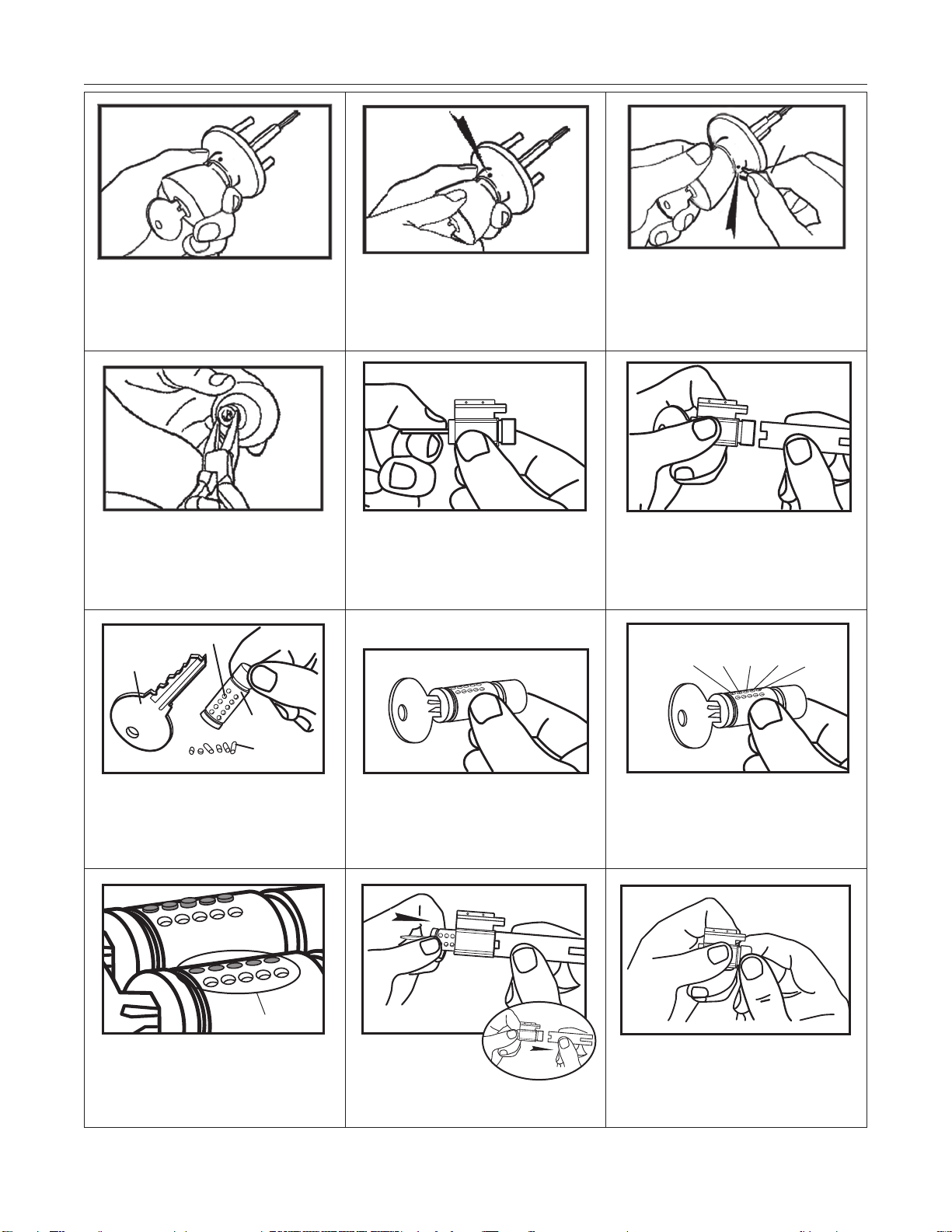
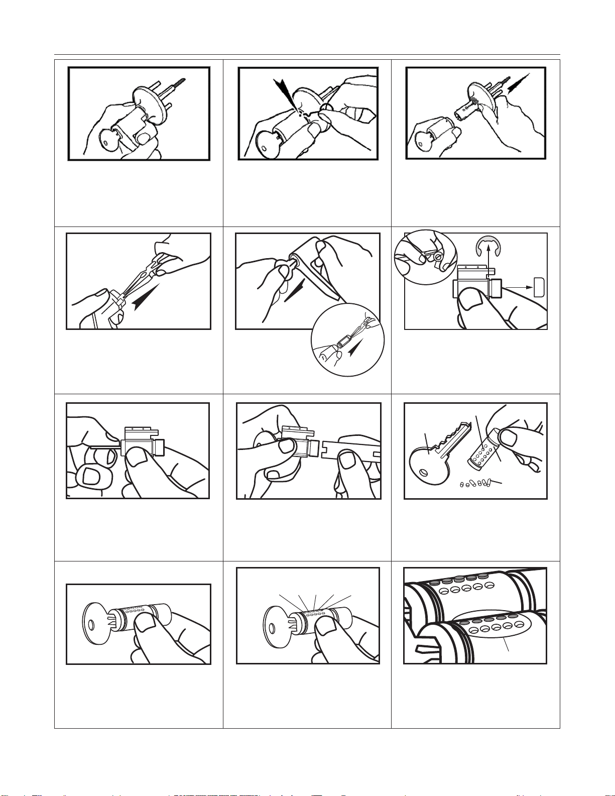
Insert the operating key and unlock the
knob. If an operating key is not available,
pick to unlock.
Turn the outside knob clockwise until the
retainer aligns with and is visible under the
poke hole.
Use the knob release tool to depress the
knob retainer and pull knob from the
spindle.
Remove knob ferrule and then remove
cylinder from knob. Remove C clip from
cylinder.
Turn plug 45° in either direction. Use the plug follower to push the plug out
of the shell. Note: Use the notched end
against the end of the plug.
Pull the key from the plug and remove pins
from all chambers.
Insert new key. If the key isn’t stamped
with a direct code, decode. Our example
key is combination 22561.
Select a bottom pin #2 from the keying kit and
place it in the first pin chamber. Key the rest of
the cylinder as: #2 in the second chamber, #5 in
the third chamber, #6 in the fourth chamber,
#1 in the fifth chamber.
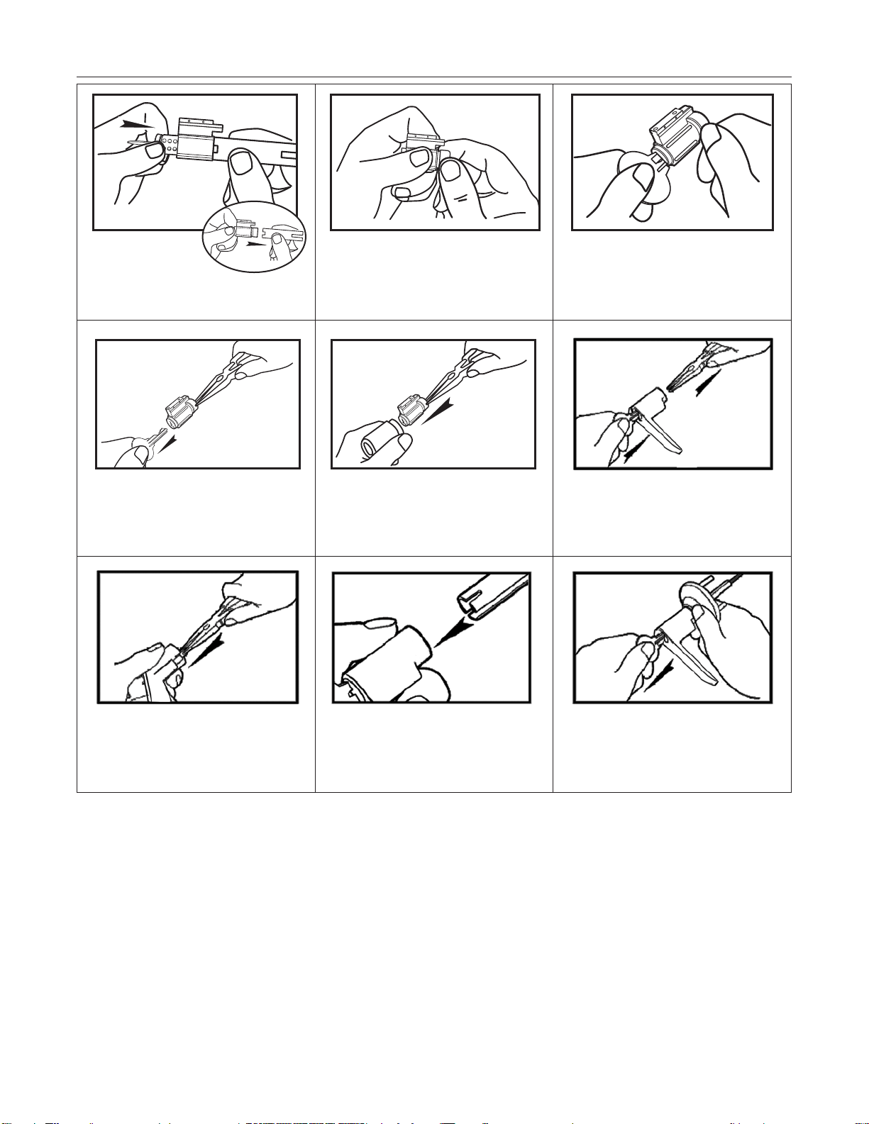
Check that all pins are flush with the
surface of the plug with the new key
inserted.
Push circlip retainer onto
the end of the plug.
Knob
Release Tool
Key
Bottom Pin
Pin Hole
Plug
1st
Hole
2
Flush w/plug sufrace
2nd
Hole
2
3rd
Hole
5
4th
Hole
6
5th
Hole
1
With the plug
turned 90° from
vertical, push follower from
the shell with the plug.
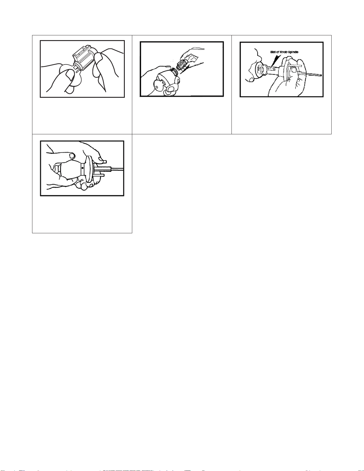
Check operation of key for functionality.
Remove key.
Place plug in position inside shell and
reinstall the C clip. Insert cylinder into
knob and replace ferrule.
With key partially inserted, align the bible
with the slot on the outside knob spindle.
Align knob and push in to engage the
retainer.
Check knob locked and unlocked to ensure
it operates properly. Reinstall lock on door
if it was removed for rekeying.
34
35
Entry Leverset Grade 3 Residential
FuNCtiON: Turn button on inside handle locks or unlocks outside and inside. Key in outside locks or unlocks. When locked, handles
are rigid. When unlocked, either will retract latch.
Part Number
Product Description
Retail Boxed
Sll0103 Sll0103KA4
Polished Brass Straight Entrance Lever
Sll0115 Sll0115K A4
Satin Nickel Straight Entrance Lever
N/A wl0103KA4
Polished Brass Wave Entrance Lever
wl0115 wl0115K A4
Satin Nickel Wave Entrance Lever
wl0112P wl0112PKA4
Aged Bronze Wave Entrance Lever
Passage Leverset Grade 3 Residential
FuNCtiON: Handle from either side retracts latch. No keys required.
Part Number
Product Description
Retail Boxed
Sll0403 Sll0403/t6P
Polished Brass Straight Passage Lever
Sll0415 Sll0415/t6P
Satin Nickel Straight Passage Lever
N/A wl0403/t6P
Polished Brass Wave Passage Lever
wl0415 wl0415/t6P
Satin Nickel Wave Passage Lever
wl0412P wl0412P/t6P
Aged Bronze Wave Passage Lever
Privacy Leverset Grade 3 Residential
FuNCtiON: Turn button on inside handle locks or unlocks outside and inside.
When locked, handles are rigid. When unlocked, either will retract latch.
36
Part Number
Product Description
Retail Boxed
Sll0303 Sll0303/t6P
Polished Brass Straight Privacy Lever
Sll0315 Sll0315/t6P
Satin Nickel Straight Privacy Lever
N/A wl0303/t6P
Polished Brass Wave Privacy Lever
wl0315 wl0315/t6P
Satin Nickel Wave Privacy Lever
wl0312P wl0312P/t6P
Aged Bronze Wave Privacy Lever
Storeroom Leverset Grade 3 Residential
FuNCtiON: Inside always unlocked. Outside handle always locked. Latch retracted by turning key.
Part Number
Product Description
Boxed
SllO0203PKA4
Polished Brass Straight Storeroom Lever
SllO0215PKA4
Satin Nickel Straight Storeroom Lever
wlRH0203KA4
Polished Brass Wave Storeroom Lever – Right-Handed
wllH0203KA4
Polished Brass Wave Storeroom Lever – Left-Handed
wlRH0215KA4
Satin Nickel Wave Storeroom Lever – Right-Handed
wllH0215KA4
Satin Nickel Wave Storeroom Lever – Left-Handed
wlRH0212PKA4
Aged Bronze Wave Storeroom Lever – Right-Handed
wllH0212PKA4
Aged Bronze Wave Storeroom Lever – Left-Handed
Leverset Rekeying Grade 3 Residential
37
Use key to unlock, if no key is available,
pick to unlock.
Use the lever release tool to depress the
retainer and release the lever.
Pull lever handle from outside spindle.
Remove plastic spacer from lever.
Do not lose.
Remove C clip and pry cap
from end of cylinder.
Turn plug 45° in either direction. Use the plug follower to push the plug out
of the shell. Note: Use the notched end
against the end of the plug.
Pull the key from the plug and remove pins
from all chambers.
Insert new key. If the key isn’t stamped
with a direct code, decode. Our example
key is combination 22561.
Select a bottom pin #2 from the keying kit and
place it in the first pin chamber. Key the rest of
the cylinder as: #2 in the second chamber, #5 in
the third chamber, #6 in the fourth chamber,
#1 in the fifth chamber.
Check that all pins are flush with the
surface of the plug with the new key
inserted.
Key
Bottom Pin
1st
Hole
2
Flush w/plug sufrace
2nd
Hole
2
3rd
Hole
5
4th
Hole
6
5th
Hole
1
Pin Hole
Plug
Remove key and
then cylinder
from lever handle.
Push circlip retainer onto
the end of the plug.
Check operation of key for functionality.
Pull key from cylinder and grab cylinder
end with pliers.
Push cylinder assembly into the lever
handle using the pliers.
Partially insert key and remove the pliers.
Replace the plastic spacer with correct
orientation.
Align the plastic spacer with the slot in the
spindle, then push lever onto spindle until
retainer snaps into place.
Check operation of lock in locked and
unlocked modes to verify functionality.
Leverset Rekeying Grade 3 Residential
38
With the plug
turned 90° from
vertical, push follower from
the shell with the plug.

Handleset Grade 3 Residential
FuNCtiON: Deadbolt thrown or retracted by key outside or thumb turn inside. Latch bolt by thumb piece outside or knob inside. No
keys required for latch bolt operation.
39
Handleset deadbolts are
not available with the
NightWatch
®
function
Part Number
Product Description
Retail Boxed
HDlBA0603 HDlBA0603KA4
Polished Brass Entrance Handleset, Ball Knob Interior
N/A HDlt u0 603K A 4
Polished Brass Entrance Handleset, Tulip Knob Interior
N/A HDlBA0615KA4
Satin Nickel Entrance Handleset, Ball Knob Interior
N/A HDlBC0612PKA4
Aged Bronze Entrance Handleset, Biscuit Knob Interior
N/A HDlwl0612PKA4
Aged Bronze Entrance Handleset, Wave Lever Interior
40
Single Cylinder Deadbolt Grade 3 Residential
FuNCtiON: Deadbolt thrown or retracted by key outside or by thumb turn inside.
Part Number
Product Description
Retail Boxed
DSO0603 DSO0603KA4
Polished Brass Single Cylinder Deadbolt
DSO0605 DSO0605KA4
Antique Brass Single Cylinder Deadbolt
DSO0615 DSO0615KA4
Satin Nickel Single Cylinder Deadbolt
DSO0612P DSO0612PKA4
Aged Bronze Single Cylinder Deadbolt
N/A
DSNO0603KA4
Polished Brass Single Cylinder Deadbolt, with BumpStop
®
N/A
DSNO0605KA4
Antique Brass Single Cylinder Deadbolt, with BumpStop
®
N/A
DSNO0615KA4
Satin Nickel Single Cylinder Deadbolt, with BumpStop
®
N/A
DSNO0612PKA4
Aged Bronze Single Cylinder Deadbolt with BumpStop
®
DSON0603 DSON0603KA4
Polished Brass Single Cylinder Deadbolt, NightWatch
®
DSON0605 DSON0605KA4
Antique Brass Single Cylinder Deadbolt, NightWatch
®
DSON0615 DSON0615KA4
Satin Nickel Single Cylinder Deadbolt, NightWatch
®
DSON0612P
N/A
Aged Bronze Single Cylinder Deadbolt, NightWatch
®
N/A
DSNON0603KA4
Polished Brass Single Cylinder Deadbolt, NightWatch
®
with BumpStop
®
N/A
DSNON0605KA4
Antique Brass Single Cylinder Deadbolt, NightWatch
®
with BumpStop
®
N/A
DSNON0615KA4
Satin Nickel Single Cylinder Deabolt, NightWatch
®
with BumpStop
®
Double Cylinder Deadbolt Grade 3 Residential
FuNCtiON: Deadbolt thrown or retracted by key in either side.
41
Part Number
Product Description
Retail Boxed
DSO0703 DSO0703KA4
Polished Brass Double Cylinder Deadbolt
DSO0705 DSO0705KA4
Antique Brass Double Cylinder Deadbolt
DSO0715 DSO0715K A4
Satin Nickel Double Cylinder Deadbolt
DSO0712P DSO0712PKA4
Aged Bronze Double Cylinder Deadbolt with BumpStop
®
N/A
DSNO0703KA4
Polished Brass Double Cylinder Deadbolt with BumpStop
®
N/A
DSNO0705KA4
Antique Brass Double Cylinder Deadbolt with BumpStop
®
N/A
DSNO0715KA4
Satin NIckel Double Cylinder Deadbolt with BumpStop
®
N/A
DSNO0712PKA4
Aged Bronze Double Cylinder Deadbolt with BumpStop
®
One-Sided Deadbolt Grade 3 Residential
Part Number
Product Description
Boxed
DSO0503
Polished Brass Single-Sided Deadbolt
DSO0505
Antique Brass Single-Sided Deadbolt
DSO0515
Satin Nickel Single-Sided Deadbolt
DSO0512P
Aged Bronze Single-Sided Deadbolt
OR
Deadbolt Rekeying Grade 3 Residential
Insert key.
Note: The rekeying procedure is the same
for brass cylinder housings or die cast
housings.
Disassemble the deadbolt, remove trim
collar from the cylinder.
Rotate the cap tool counterclockwise to
loosen the cap.
Remove cap and tailpiece.
Remove cap pin and cap pin spring
Rekey using a follower as instructed under
Leverset Rekeying.
Check reassembled cylinder to ensure
functionality but do not remove the key.
Insert the cap pin spring and the cap pin. Put cap and tailpiece in position.
Tighten cap with cap tool and check key
for ease in turning. If tight, loosen cap one
retention point and check.
42
Tail
Piece
Locking
Nut
Plug
Spring
Cylinder Housing
Retaining
Pin
Recodable Multi-Family
Master Lock Recodable Door Hardware allows property owners
and managers to take control of the process of changing locks
with every change in occupancy. With the simple change tool that
is provided with each lock they can instantly rekey door locks
whenever needed and as often as needed.
Quick – Literally takes just seconds to recode a Master Lock
recodable lock
Cost Effective – Eliminates cost of lock replacement or rekeying
Easy – Takes just four easy steps
43
1
With door open, insert key into keyway of
deadbolt. Turn key 90 degrees clockwise to
recode position. Do not remove key from
keyway.
With key still in keyway, insert Change Tool into
notch above the keyway.
Without removing the Change Tool, remove
old key. With Change Tool still in place, insert
new key.
Remove Change Tool – your lock is now rekeyed to
the new key.
2
3
4
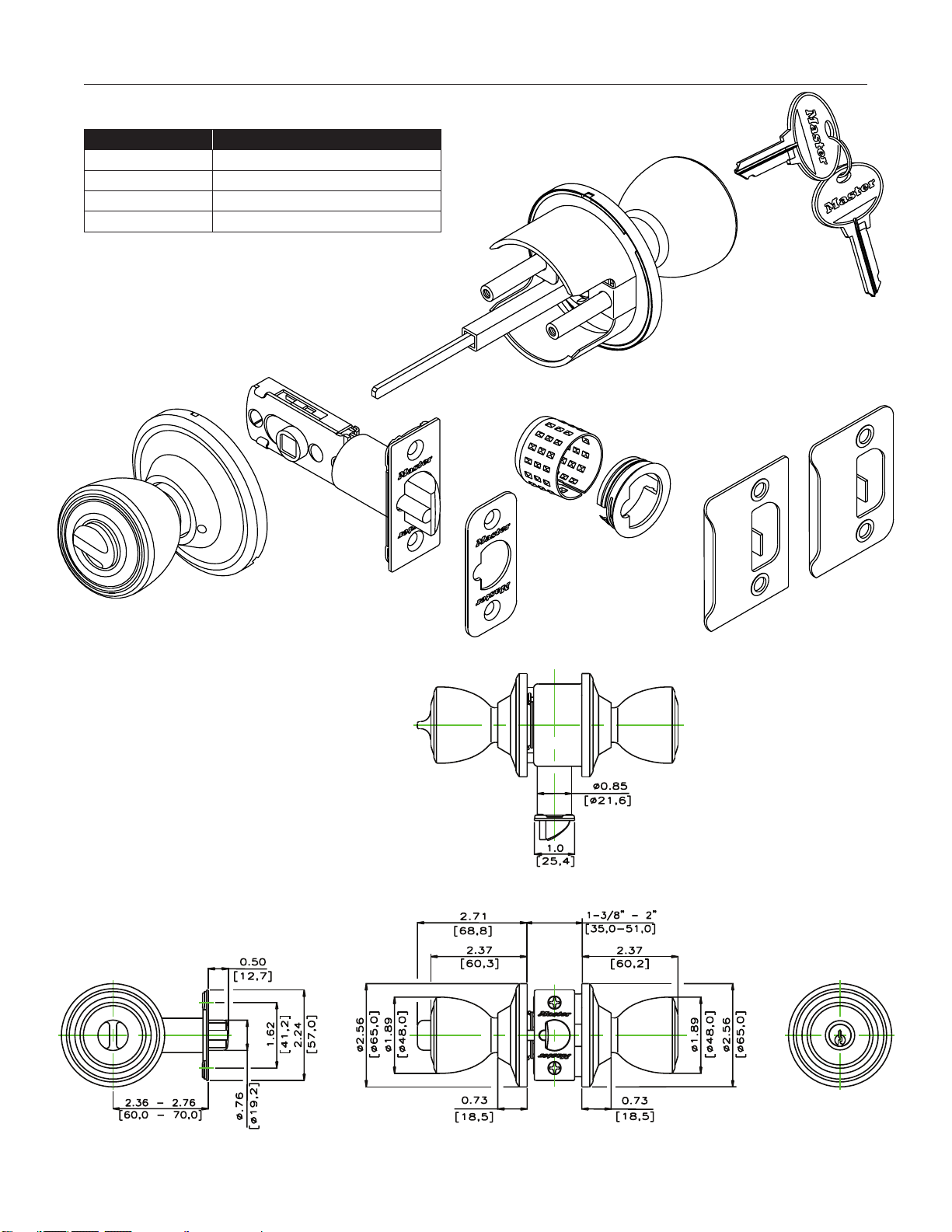
Entry Knobset Recodable Multi-Family
FuNCtiON: Inside handle pushbutton locks the outside handle.
Unlock outside handle with a key or by turning inside handle.
44
Product Number Product Description
tPCR103
Polished Brass Tulip Recodable Entrance
tPCR115
Satin Nickel Tulip Recodable Entrance
CACR103
Polished Brass Ball Recodable Entrance
CACR115
Satin NIckel Ball Recodable Entrance
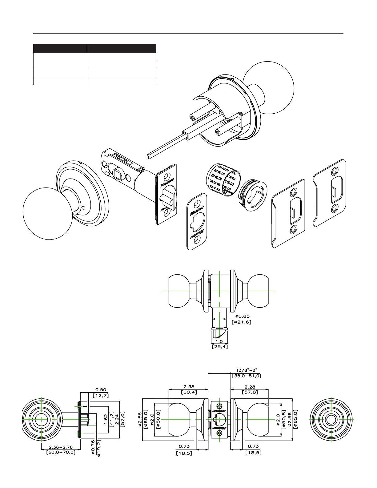
Passage Knobset Recodable Multi-Family
FuNCtiON: Inside and outside handles always unlocked; turning either retracts latch. No keys required.
45
Product Number Product Description
tPC0403
Polished Brass Tulip Passage
tPC0415
Satin Nickel Tulip Passage
CAC0403
Polished Brass Ball Passage
CAC0415
Satin Nickel Ball Passage
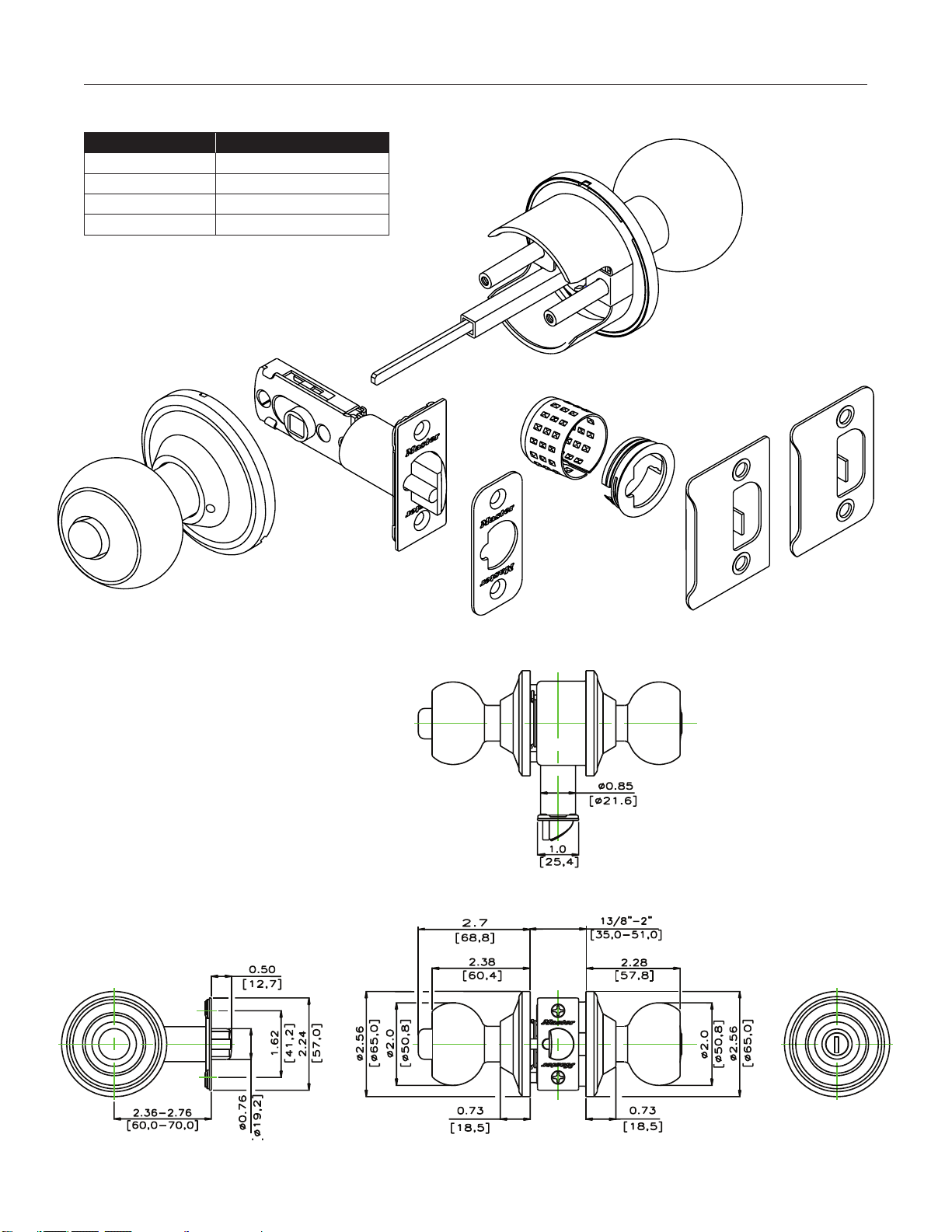
Privacy Knobset Recodable Multi-Family
FuNCtiON: Inside handle pushbutton locks outside handle. Emergency release in outside handle. Closing the door or turning inside
handle releases the pushbutton.
46
Product Number Product Description
tPC0303
Polished Brass Tulip Privacy
tPC0315
Satin Nickel Tulip Privacy
CAC0303
Polished Brass Ball Privacy
CAC0315
Satin Nickel Ball Privacy
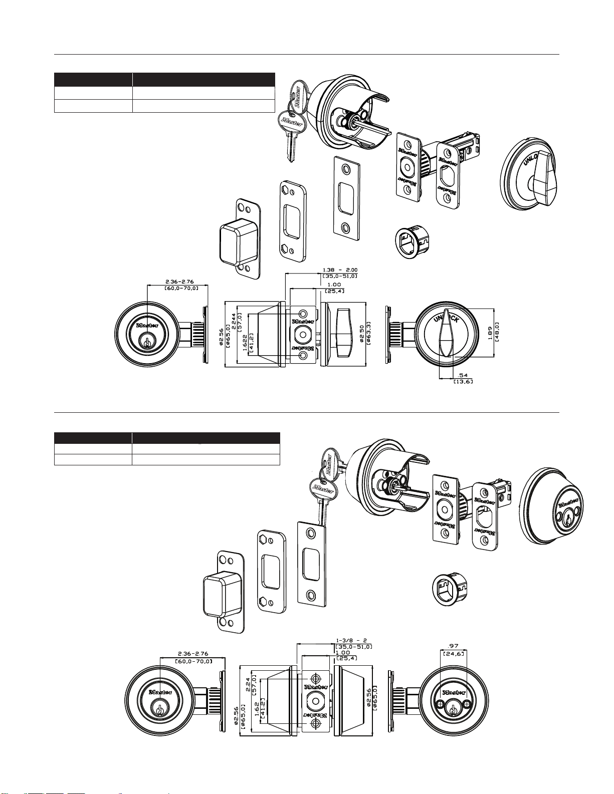
Single Cylinder Deadbolt Recodable Multi-Family
FuNCtiON: Deadbolt thrown or retracted by key outside or by thumb-turn inside.
47
Product Number Product Description
DSCR603
Polished Brass Single Cylinder Deadbolt
DSCR615
Satin Nickel Single Cylinder Deadbolt
Double Cylinder Deadbolt Recodable Multi-Family
FuNCtiON: Deadbolt thrown or retracted by key in either side.
Product Number Product Description
DDCR703
Polished Brass Double Cylinder Deadbolt
DDCR715
Satin Nickel Double Cylinder Deadbolt

Service Kits and Component Parts
Keying Kit 2201 (for 1176 Keyway)
Supplemental Bottom Spool Pin Kit 291BS1 (for 1176 Keyway)
Combination Deadbolt
Disrupter Spring PKG50998
Fly PKG50994
48
Contents
200 ea. Bottom Pins 1 through 7
50 ea. Master Pins 2 through 6
100 ea. Top Pins
200 ea. Driver Springs
10 ea. Retaining Caps
50 ea. C Clips
25 ea. Pin Covers
50 Cap Pins
50 ea. Cap Pin Springs
1 ea Tweezers
1 ea Cap Tool
1 ea Lever release Tool
1 ea Knob Release Tool
1 ea Follower
1 ea Pin & Key Gauge
Contents
Spool Bottom Pins
Size Part Number
1 0291-82360
2 0291-82361
3 0291-82362
4 0291-83766
5 0291-83767
6 0291-83768
7 0291-83769
Driver Springs 0291-80083
Knob
Release Tool
Locking Nut Tool
Plug
Follower
Pin
Tweezer
KEY
PIN
7 6 5 4 3 2 1
1 2 3 4 5 6 7
FOR HEIGHT GAUGE
KEY
PIN
KEY
PIN
7 6 5 4 3 2 1
1 2 3 4 5 6 7
FOR HEIGHT GAUGE
KEY
PIN
STAINL
E
S
S
Pin Gauge
Plastic
Box
Identification Chart
Lever
Release
Tool
Brass
Follower


19,1
[ 0.75]
57,0
[2.24]
12,7
[0.50]
60,0 & 70,0
[2.36 & 2.75]
75,0
[ 2.95]
25,4 & 28,4
[1.00 &1.12]
52,0
[ 2.05]
35,0~45,0
[1.38~1.75]
101,6
[4.00]
48,1
[1.89]
162,4
[6.39]
1
2
5
3 4
6
7
8
9
10
11
12
13
14
15
16
© 2012 Master Lock Company All Rights Reserved
www.masterlock.com www.masterdoorlock.com
Master Lock Company LLC, Milwaukee, WI 53154 U.S.A. 800-308-9244
Master Lock Canada, Oakville, Ontario L6H 5S7 Canada 800-227-9599
7000-0101 CI 1.5M Printed in U.S.A. 4/12