Home
Bookmarks
Home
Sony
Sony PCV-L630 User Manual
Page 71
Sony PCV-L630 Vaio Slimline Lcd Pc
User Manual - Page 71
For PCV-L630.
PDF File Manual
,
110 pages
,
Read Online
|
Download pdf file
Notice to Users
Safety Information
Ownerâs Record
Regulatory Information
FCC Part 68
Telephone Consumer Protection Act of 1991
Contents
Identifying Components
Front View
Drives
Buttons and Switches
Indicators
Connectors
Slots
Rear View
I/O Connectors
PRINTER Port
SERIAL Port
MONITOR
USB Connectors
PHONE, MIC, LINE IN, and LINE OUT
i.LINK (IEEE-1394)
LCD
KEYBOARD/MOUSE
LINE and PHONE
Expansion Slot
Configuring Your System
Accessing the CMOS Setup Utility
Changing the Display's Power Management Settings
Configuring the System Board
CMOS Jumper
CPU Frequency Ratio Multiplier Switches
AGP_INT Switch
VGA Switch
Removing, Installing, and Replacing Components
Removing the System Cover
Replacing the System Cover
Installing an Add-In Card
Removing an Add-in Card
Setting the Configuration Switches
Setting the CMOS Jumper
Replacing the Lithium Battery
Installing System Memory
Removing a Memory Module
Replacing the Hard Drive
Removing a Slot Cover
Covering an Open I/O Slot
System Board
Connectors
Front Panel Header
Diskette Drive (FLOPPY) Connector
IDE Connectors
PCI Slot Connectors
Memory Module (DIMM) Connectors
Power (ATX PWR) Connector
Fan (CPU FAN, CTRL PWR) Connectors
Keyboard/Mouse (KB/MOUSE) Connector
USB Connectors
PRINTER, SERIAL, and VGA MONITOR Connectors
LCD Connector
Wake On LAN (WOL_CON) Connector
LINE IN and LINE OUT Connectors
PHONE and MIC Connectors
Sony Memory Stick Slot Connector
i.LINK Interface Header Connectors
i.LINK Connectors
Configuration Jumper and Switches
CMOS Jumper
Configuration Switches (SW)
Fax/Modem Card
CMOS Setup Options
STANDARD CMOS SETUP Screen
BIOS FEATURES SETUP Screen
CHIPSET FEATURES SETUP Screen
POWER MANAGEMENT SETUP Screen
PNP AND PCI SETUP Screen
LOAD SETUP DEFAULTS Screen
SUPERVISOR PASSWORD Screen
USER PASSWORD Screen
IDE HDD AUTO DETECTION Screen
SAVE & EXIT SETUP Screen
EXIT WITHOUT SAVING Screen
Miscellaneous Technical Information
About User and Supervisor Passwords
Beep Code Error Messages
PCI Configuration Status and Error Messages
DMA Channel Assignments
IRQ Assignments
System I/O Address Map
Memory Map
Specifications
Processor
Chipset
PCI Bus
Memory Modules (DIMMs)
DIMM Configurations
L2 Cache
Graphics
Audio
Communications
I/O and Expansion Slots
i.LINK Interface
Drives and Controllers
System CMOS
Index
A
B
C
D
E
F
G
H
I
J
K
L
M
N
O
P
R
S
T
U
V
W
Page 71/110
Page 1
Page 2
Page 3
Page 4
Page 5
Page 6
Page 7
Page 8
Page 9
Page 10
Page 11
Page 12
Page 13
Page 14
Page 15
Page 16
Page 17
Page 18
Page 19
Page 20
Page 21
Page 22
Page 23
Page 24
Page 25
Page 26
Page 27
Page 28
Page 29
Page 30
Page 31
Page 32
Page 33
Page 34
Page 35
Page 36
Page 37
Page 38
Page 39
Page 40
Page 41
Page 42
Page 43
Page 44
Page 45
Page 46
Page 47
Page 48
Page 49
Page 50
Page 51
Page 52
Page 53
Page 54
Page 55
Page 56
Page 57
Page 58
Page 59
Page 60
Page 61
Page 62
Page 63
Page 64
Page 65
Page 66
Page 67
Page 68
Page 69
Page 70
Page 71
Page 72
Page 73
Page 74
Page 75
Page 76
Page 77
Page 78
Page 79
Page 80
Page 81
Page 82
Page 83
Page 84
Page 85
Page 86
Page 87
Page 88
Page 89
Page 90
Page 91
Page 92
Page 93
Page 94
Page 95
Page 96
Page 97
Page 98
Page 99
Page 100
Page 101
Page 102
Page 103
Page 104
Page 105
Page 106
Page 107
Page 108
Page 109
Page 110
Contents
Table of Contents
Search
Previous
Next
Bookmarks
Loading ...
Loading ...
Loading ...
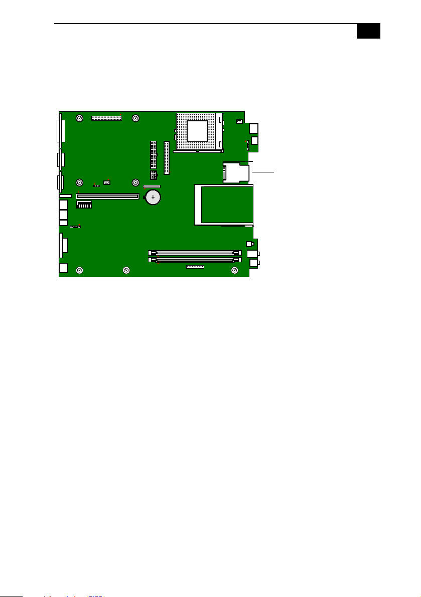
System
Board
63
Sony Memory Stick Slot Connect
or
The Sony Mem
ory Stick
slot conn
ector is a 10-
pin MCR 103
-10S
connector
.
O
N
12345
6
KY0097.VS
D
Sony Memory Stick
Loading ...
Loading ...
Loading ...
File type: PDF
File name: 35599149_pcv-l630.pdf
File size: 1.47 MB
File Language: English
Pages: 110
Author: Sony
File created: 2000-03-02
Published: 2021-05-28
Updated: 2023-08-25
Download File
Table of Contents
×
Notice to Users
2
Safety Information
2
Ownerâs Record
2
Regulatory Information
3
FCC Part 68
4
Telephone Consumer Protection Act of 1991
4
Contents
5
Identifying Components
9
Front View
10
Drives
11
Buttons and Switches
12
Indicators
13
Connectors
14
Slots
15
Rear View
16
I/O Connectors
17
PRINTER Port
17
SERIAL Port
17
MONITOR
17
USB Connectors
18
PHONE, MIC, LINE IN, and LINE OUT
18
i.LINK (IEEE-1394)
19
LCD
19
KEYBOARD/MOUSE
19
LINE and PHONE
20
Expansion Slot
20
Configuring Your System
21
Accessing the CMOS Setup Utility
22
Changing the Display's Power Management Settings
23
Configuring the System Board
25
CMOS Jumper
25
CPU Frequency Ratio Multiplier Switches
27
AGP_INT Switch
28
VGA Switch
29
Removing, Installing, and Replacing Components
31
Removing the System Cover
32
Replacing the System Cover
33
Installing an Add-In Card
34
Removing an Add-in Card
35
Setting the Configuration Switches
37
Setting the CMOS Jumper
38
Replacing the Lithium Battery
39
Installing System Memory
42
Removing a Memory Module
44
Replacing the Hard Drive
49
Removing a Slot Cover
52
Covering an Open I/O Slot
53
System Board
55
Connectors
56
Front Panel Header
56
Diskette Drive (FLOPPY) Connector
57
IDE Connectors
58
PCI Slot Connectors
59
Memory Module (DIMM) Connectors
60
Power (ATX PWR) Connector
61
Fan (CPU FAN, CTRL PWR) Connectors
62
Keyboard/Mouse (KB/MOUSE) Connector
63
USB Connectors
64
PRINTER, SERIAL, and VGA MONITOR Connectors
65
LCD Connector
67
Wake On LAN (WOL_CON) Connector
68
LINE IN and LINE OUT Connectors
69
PHONE and MIC Connectors
70
Sony Memory Stick Slot Connector
71
i.LINK Interface Header Connectors
72
i.LINK Connectors
73
Configuration Jumper and Switches
74
CMOS Jumper
74
Configuration Switches (SW)
75
Fax/Modem Card
79
CMOS Setup Options
81
STANDARD CMOS SETUP Screen
82
BIOS FEATURES SETUP Screen
83
CHIPSET FEATURES SETUP Screen
86
POWER MANAGEMENT SETUP Screen
88
PNP AND PCI SETUP Screen
90
LOAD SETUP DEFAULTS Screen
92
SUPERVISOR PASSWORD Screen
92
USER PASSWORD Screen
92
IDE HDD AUTO DETECTION Screen
92
SAVE & EXIT SETUP Screen
92
EXIT WITHOUT SAVING Screen
92
Miscellaneous Technical Information
93
About User and Supervisor Passwords
94
Beep Code Error Messages
95
PCI Configuration Status and Error Messages
96
DMA Channel Assignments
97
IRQ Assignments
98
System I/O Address Map
99
Memory Map
101
Specifications
103
Processor
103
Chipset
103
PCI Bus
103
Memory Modules (DIMMs)
103
DIMM Configurations
104
L2 Cache
104
Graphics
104
Audio
105
Communications
105
I/O and Expansion Slots
105
i.LINK Interface
106
Drives and Controllers
106
System CMOS
106
Index
107
A
107
B
107
C
107
D
108
E
108
F
108
G
108
H
108
I
108
J
108
K
108
L
109
M
109
N
109
O
109
P
109
R
109
S
109
T
110
U
110
V
110
W
110
Search:
×
Search