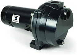
Owner’s Manual
WALS Series
Cast Iron
Sprinkler Pumps
General Safety . . . . . . . . . . . . . . . . . . . . 2
Installation . . . . . . . . . . . . . . . . . . . . . .3-5
Electrical . . . . . . . . . . . . . . . . . . . . . . . . .6
Operation . . . . . . . . . . . . . . . . . . . . . . . . 7
Troubleshooting . . . . . . . . . . . . . . . . . . . 8
Repair Parts . . . . . . . . . . . . . . . . . . . . . . 9
Warranty . . . . . . . . . . . . . . . . . . . . . . . . 10
TABLE OF CONTENTS
2
Fill Pump with water to prime: Ensure pump body is lled with water to discharge.
Motor’s Electrical Settings: Set motor to proper voltage.
Help Line: Call 1-844-394-2604 for assistance
STOP
Before you start
GENERAL SAFETY
SAFETY LABELS
Important Safety Instructions Carefully read and follow all safety instructions in this manual and on pump.
SAVE THESE INSTRUCTIONS – This manual contains important instructions that should be followed during installation,
operation, and maintenance of the product. Save this manual for future reference.
This is the safety alert symbol. When you see this symbol on your pump or in this manual, look for one of the
following signal words and be alert to the potential for personal injury!
Indicates a hazard which, if not avoided,
will result in death or serious injury.
Indicates a hazard which,if not avoided,
could result in death or serious injury.
Indicates a hazard which,if not avoided,
could result in minor or moderate injury.
NOTICE
indicates practices not related to personal injury.
Keep safety labels in good condition. Replace missing or
damaged safety labels.
• Keep pump equipment out of the reach of children! Failure
to follow the directions given could cause serious risk to
individuals or objects.
• DO NOT work on pump until power is disconnected.
• DO NOT cut o ground pin or use an adapter tting.
• DO NOT use an extension cord.
• The pump power cord should be connected to a sepa-
rately fused, grounded line with a minimum amp capacity
listed on page 6. It can be connected to a non-fused
breaker at the recommended amperes.
• ELECTRICAL PRECAUTIONS - Before servicing the
pump, always shut o the main power breaker and then
unplug the pump. Make sure you are not standing in
water and are wearing insulted protective shoes under
ood conditions. Contact your local electric company or
a qualied licensed electrician for dicconnecting electrical
service prior to pump removal.
• Follow all local electrical and safety codes, as well as
the National Electrical Code (NEC) and the Occupational
Safety and Health Act (OSHA)
• Replace damaged or worn wiring cord immediately.
• Do not kink power cable and never allow the cable to
come in contact with oil, grease, hot surfaces, or
chemicals.
• Wire motor to correct supply. See motor nameplate and
wiring diagrams and check voltage of power supply.
• Unit must be securely and adequately electrically ground-
ed. This can be accomplished by wiring the unit to a
ground metal-clad raceway system or by using a separate
ground wire connected to the bare metal of the motor
frame or other suitable means.
• Do not disassemble the motor housing. This pump has
no repairable internal parts and disassembling may cause
leakage or dangerous electrical wiring issues.
• Make certain the electrical power source is adequate for
the requirements of the pump.
• Install pressure relief valve in the discharge pipe. Release
all pressure on system before working on any component.
• The following may cause severe damage to pump and will
void the warranty.
- Using an extension cord.
- Cutting o the ground pin or using an adapter tting.
- Working on the pump or switch while plugged in.
- Removing motor housing, unscrewing impeller or other
wise removing impeller seal
- Running the pump continuously.
- Pumping chemicals or corrosive liquids.
- Pumping gasoline or other ammable liquids.
• This pump is only to be used for water systems.
• Protect the power cable from coming in contact with
sharp objects.
• Do not run pump dry.
• Pump and plumbing must be full of water before startup.
• Do not pump water which contains sand, mud, silt or
debris.
• Be careful when touching the exterior of a motor. It may
be hot enough to be painful or cause injury.
• Do not allow pump or any system component to freeze.
To do so will void the warranty.
continued
Before You Install Your Pump
NOTICE
1. The pump’s water suction inlet must not be move
than 20’ above the water level.
2. Long runs and many ttings increase friction
and reduce water ow to the pump. Locate pump
as close to water source as possible; use as few
elbows and ttings as possible. Be sure suction
line is straight and angles up toward pump to
avoid air lock.
3. Be sure well and pipe are clear of sand, dirt and
scale. Foreign matter will plug pump and void
warranty. Use new pipe for best results.
4. Protect pump and all piping from freezing.
Freezing will split pipe, damage pump and void
warranty. Check locally for frost protection require
ments. Pipe cannot be installed above frost line
and pump must be insulated.
5. Foot or check valves must be installed in suction
pipe to optimize pump suction.
6. Be sure all pipes and valves are clean and in
good shape.
7. No air pockets in suction pipe.
8. No leaks in suction pipe. Use Teon tape or
other approved sealants to seal pipe joints.
9. Unions installed near pump and well will aid in
servicing. Leave room to use wrenches.
Risk of explosion.
Do not ground to a gas supply line.
Pump body may explode if used as a booster pump
or other than a lawn sprinkling application.
Risk of burns.
Motor normally operates at high temperature and will
be too hot to touch. It is protected from heat dam-
age during operation by an automatic internal cuto
switch.
Before handling pump or motor, stop motor and allow
it to cool for 20 minutes.
Well Pipe Installation
NOTICE
Use installation method below which matches your
water source.
3
INSTALLATION
!
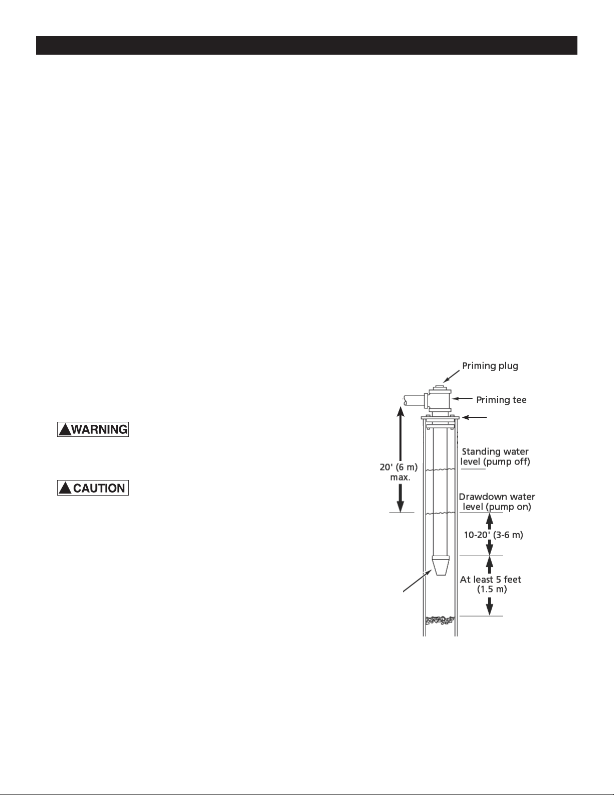
Cased Well/Dug Well Installation- Figure 1
1. Inspect foot or in line check valve to be sure it
works freely. Inspect strainer to be sure it is clean
and secure.
2. If using foot valve, connect foot valve and
strainer to rst length of suction pipe and lower
pipe into well. Add sections of pipe as needed,
using Teon tape on male threads. Note: use
1-1/2” pipe for suction pipe. Be sure all suction
pipe is leak proof or pump will lose prime and fail
to pump. Install foot valve 10 to 20 ft. (3 to 6 m)
below lowest level to which water will drop
while pump is operating (pumping water level).
Your well driller can furnish this information.
3. To prevent sand and sediment from entering
pumping system, foot valve/strainer should be at
least 5 ft. (1.5 m) above bottom of well.
4. When proper depth is reached, install sanitary well
seal over pipe and in well casing. Tighten bolts to
seal casing.
5. When using foot valve, a priming tee and plug are
recommended. (Fig. 1).
!
Foot
Valve/Strainer
Suction pipe
Well seal
Figure 1 -Cased/Dug Well Installation
4
INSTALLATION
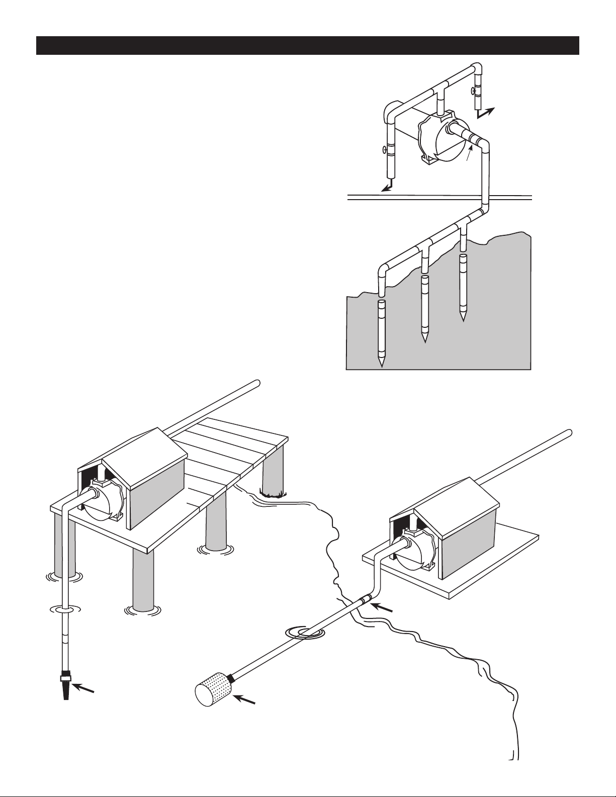
Driven Point Installation-Figure 2
1. Connect suction pipe to drive point (Fig. 2).
Keep horizontal pipe run as short as possible.
Use Teon tape on male pipe threads. Multiple
well points may be necessary to provide
sucient water to pump.
2. Install check valve in horizontal pipe. Flow
arrow on check valve must point toward pump.
Surface Water Applications- Figure 3A and 3B
A. Vertical from Surface Water to Pump.
1. Foot Valve with Strainer attached to PVC
pipe.
2. Install check valve in horizontal pipe.
B. Horizontal from Surface Water to Pump
1. Attach Foot Valve to PVC pipe
2. Next attach the Strainer Basket to Foot Valve
3. Install check valve in horizontal pipe.
Figure 2
Driven point installation,
multiple well points
To sprinkler
heads
Discharge pipe
Gate valve
Gate valve
To sprinkler heads
Check
valve
Multiple
well heads
Check
Valve
Strainer Basket
Foot Valve
with Strainer
Figure 3A - Vertical
Figure 3B - Horizontal

INSTALLATION
5
Lawn Sprinkling Application
This pump is designed for lawn sprinkling. When prop-
erly installed it will deliver adequate water and pressure
from any well source.
Pump/Piping Installation
If turning pump on and o by pressure, a pressure
switch and tank are required. For proper follow tank and
switch instructions or contact a qualied plumber/elec-
trican.
Use rigid pipe. Do not use hose or plastic tubing. See
“Well Pipe Installation” for more information.
NOTICE
Use only PTFE pipe thread sealant tape to joint com-
pounds for making all threaded connections to the
pump itself.
Do not use pipe joint compounds on plastic pumps:
they can react with the plastic in pump components.
Make sure that all pipe joints in the suction pipe are air
tight as well as water tight. If the suction pipe can suck
air, the pump will not be able to pull water from the well.
1. Bolt pump to solid, level foundation.
2. Support all piping connected to pump.
3. Wrap 1-1/2 to 2 layers of Teon tape clockwise
(as you face end of pipe) on all male threads being
attached to pump.
4. Tighten joints hand tight plus 1-1/2 turns. Do not
overtighten.
5. Replace prime plug with pressure gauge. This will aid
in sizing zones, troubleshooting, and following pump
performance chart.
NOTICE
For long horizontal pipe runs, install a priming tee
between check valve and well head (Fig. 1).
Pipe from Well to Pump
1. Pump performance will be decreased if the pipe
diameter is less than the inlet size of the pump. In
proper installation, the pipe size equals the inlet size.
2. To aid priming on well point installations, install line
check valve. Be sure check valve ow arrow points
toward pump.
Pipe from Pump to Sprinkler Heads
Discharge pipe size should be increased to reduce
pressure losses caused by friction on long pipe runs.
• Up to 100’ (30.5 m) run: Same size as pump dis
charge port.
• 100’ – 300’ (30.5 – 91.4 m) run: Increase one
pipe size.
• 300’ – 600’ (91.4 – 182.9 m) run: Increase two
pipe sizes.
6
ELECTRICAL
Disconnect power before working on
pump, motor, pressure switch or wiring
Motor may be hot. Allow to cool 20
minutes.
Water pressure may have built up in
the pump, pipes and/or tank. Drain
water to relieve pressure.
!
!
Wiring Connections
Risk of electric shock. Electricity
can shock, burn or kill.
1. To avoid dangerous or fatal electrical shock, turn OFF
power to motor before working on electrical
connections.
2. Ground motor before connecting to electrical power
supply. Failure to ground motor can cause severe or
fatal electrical shock hazard.
3. Supply voltage must be within +/- 10% of nameplate
voltage. Incorrect voltage can cause re or damage
motor and voids warranty. If in doubt consult a
licensed electrician.
4. Use wire size specied in Wiring Chart (below). If
possible, connect pump to a separate branch circuit
with no other appliances on it.
5. Do not ground to a gas supply line.
6. Wire motor according to diagram on motor nameplate.
If nameplate diagram diers from diagrams above,
follow nameplate diagram.
7. If this procedure or the wiring diagrams are
confusing, consult a licensed electrician.
Wiring Chart Recommended Wire and Fuse Sizes for 115 and 230 volts
BRANCH
AWG
DISTANCE IN FEET FROM MOTOR TO SUPPLY
MAX. LOAD
FUSE
MIN. WIRE
0-100 101-200 201-300 301-400 401-500
MOTOR HP VOLTS AMP RATING AMP SIZE (mm
2
) AWG WIRE SIZE (mm
2
)
1 115/230 16.32/8.16 30/15 12/14 (3/2) 12/14 (8.4/2) 8/14 (2/2) 6/14 (14/2) 6/12 (14/3) 4/10 (21/5.5)
1-1/2 115/230 20.09/10.05 30/15 10/14 (5.5/2) 12/14 (8.4/2) 8/14 (8.4/2) 6/12 (14/3) 4/10 (21/5.5) 4/10 (21/5.5)
2 115/230 20.75/10.38 30/20 10/14 (5.5/2) 6/14 (14/2) 8/14 (8.4/2) 6/12 (14/3) 4/10 (21/5.5) 4/10 (21/5.5)
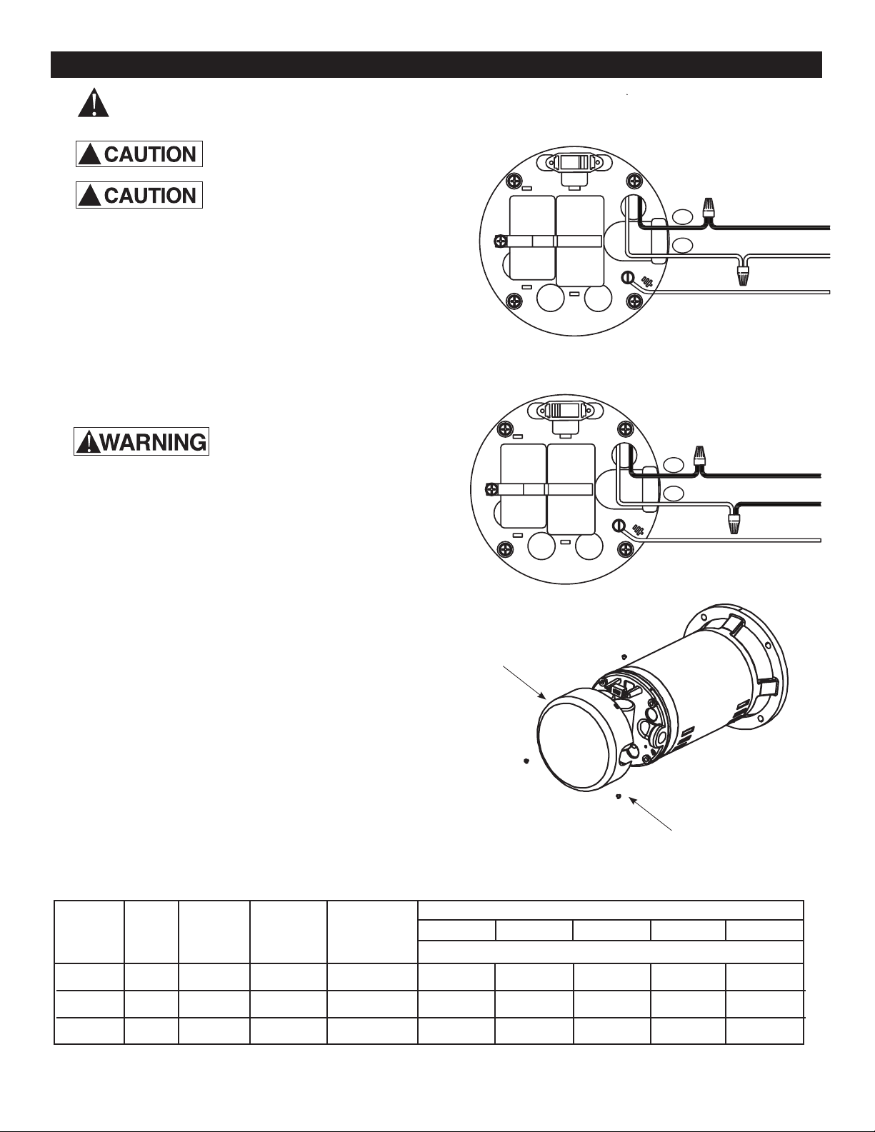
Motor Switch Settings
Motors are designed to run on either 115 volt or 230 volt
current. Be sure the motor’s current is set to match the
current being supplied to your motor from the electrical
source.
To ensure your motor is set at the correct current setting
remove the rear cover from the motor. Inspect the wiring
connections to ensure they are set correctly.
Use for EFLS10, EFLS15 and EFLS20
Screws
Motor Cover
Set for 115V
Set for 230V
HOT
To Breaker
To Breaker
Neutral
HOT
To Breaker
To Breaker
HOT
115
230
L1
L2
L1
L2
Ground Wire
Ground Wire
Priming the Pump
NOTICE ‘Priming’ refers to pump expelling all air in the
system and beginning to move water from its source out
into system. It does not refer only to pouring water into
pump (although pouring water in is usually the rst step).
Risk of burns. NEVER run pump dry.
Running pump without water may cause pump to over-
heat, damaging seal and possibly causing burns to per-
sons handling pump. Fill pump with water before starting.
Step 1. Remove priming plug.
Step 2. Make sure suction and discharge valves and
any hoses on discharge side of pump are
open.
Step 3. Fill pump and suction pipe with water (Fig. 4).
Step 4. Replace priming plug, using Teon tape on
thread; tighten plug.
NOTICE If priming tee and plug have been
provided for long horizontal run, be sure to
ll suction pipe through this tee and replace
plug. (Use Teon tape on plug.)
Step 5. Start pump; water should be produced in 10
minutes or less, time depends on depth to
water (not more than 20’ (6 m)) and length of
horizontal run (10’ (3 m)) of horizontal
suction pipe = 1’ ((30.5 m) of vertical lift due
to friction losses in pipe). If no water is
produced within 10 minutes, stop pump,
release all pressure, remove priming plug, rell
and try again.
Risk of explosion and scalding.
NEVER run pump against closed discharge. To do so
can boil water inside pump, causing hazardous pressure
in unit, risk of explosion and possibly scalding persons
handling pump (Fig. 5). Replace priming plug with pres-
sure gauge to monitor pressure so that is it not allowed to
exceed maximum pumping pressures according to perfor-
mance chart.
To prevent explosion be sure discharge (valve, pistol grip
hose nozzle, etc.) is open whenever pump is running.
Monitor pump body and piping temperature. Motor will
warm up; this is normal. If pump body or piping begins
to feel warm to touch, shut o pump and allow system to
cool. Release all pressure in system and rell pump and
piping with cold water.
7
Figure 4
Fill pump before starting
Figure 5
Do not run pump with outlet shut o
Hazardous Pressure,
Install pressure relief valve in discharge pipe.
Release all pressure on system before working on
any component.
!
!
OPERATION
Risk of electric shock. Electricity can shock, burn or kill. To discharge capacitor, hold insulated
handle screwdriver BY THE HANDLE and short capacitor terminals together. Do not touch metal screwdriver blade or
capacitor terminals. If in doubt, consult a qualifi ed electrician.
8
TROUBLE SHOOTING
SYSTEM
Motor will not run
Motor runs hot and
overload kicks off or motor
does not run and only
hums.
Motor runs but no
water is delivered*
*Stop pump; then check
prime before looking for
other causes. Unscrew
priming plug and see if
water is in priming hole
Pump does not deliver
water to full capacity.
Pump leaks around clamp
!
POSSIBLE CAUSE(S)
Disconnect switch is off
Fuse is blown or circuit breaker tripped
Starting switch is defective
Wires at motor are loose, disconnected, or wired
incorrectly
Motor is wired incorrectly
Voltage is too low
Pump in new installation did
not pick up prime through:
1. Improper priming
2. Air leaks
3. Leaking foot valve or check valve
4. Pipe size too small
Pump has lost prime through:
1. Air leaks
2. Water level below suction pipe inlet
Impeller is plugged
Check valve or foot valve is stuck shut
Pipes are frozen
Foot valve and/or strainer are buried in sand or mud
Water level in well is lower than estimated.
Steel piping (if used) is corroded or limed, causing
excess friction
Piping is too small in size
Pump not being supplied with enough water
Clamp loose
CORRECTIVE ACTION
Be sure switch is on.
Replace fuse or reset circuit breaker.
DISCONNECT POWER; Replace starting switch
Refer to instructions on wiring. DISCONNECT POWER; check and tighten all
wiring.
Refer to instructions on wiring.
Check with power company. Install heavier wiring if wire size is too small (See
Electrical/Wiring Chart)
In new installation:
1. Re-prime according to instructions.
2. Check all connections on suction line and AVC with shaving cream.
3. Replace foot valve or check valve.
4. Re-pipe using size of suction and discharge ports on pump.
In installation already in use:
1. Check all connections on suction line and shaft seal.
2. Lower suction line into water and re-prime. If receding water level in
well exceeds 25’ (7.6M0, a deep well pump is needed.
Clean impeller
Replace check valve or foot valve.
Thaw pipes. Bury pipes below frost line. Heat pit or pump house.
Raise foot valve and/or strainer above bottom of water source.
A deep well jet will be needed if your well is more than 25’ (7.6M) depth to
water.
Replace with plastic pipe where possible, otherwise with new steel pipe.
Use larger piping.
Add additional well points
STOP PUMP, tighten clamp nut 1-2 turns. Alternately tighten and tap on clamp
with mallet to seat O-Ring. Do not overtighten.
For parts or assistance, call ECO-FLO Customer Service at 1-877 326-3561
For parts or assistance, call ECO-FLO Customer Service at 1-877 326-3561
Performance Chart in GPM
MODEL HP 10 20 30 40
DISTANCE OF
PUMP ABOVE
WATER
DEPTH GPM (gallons per minute) @ depths
5’ 56 52 45 20
EFLS10 1
10’ 52 48 40 14
15’ 49 45 37
20’ 45 40 30
5’ 60 56 51 37
EFLS15 1-1/2
10’ 53 50 46 32
15’ 47 44 41 25
20’ 41 38 34 22
5’ 70 66 61 36
EFLS20 2
10’ 65 61 55 27
15’ 60 57 51 26
20’ 53 50 45 13
8
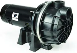
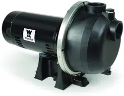
WA10LS
WA15LS
WA20LS
9
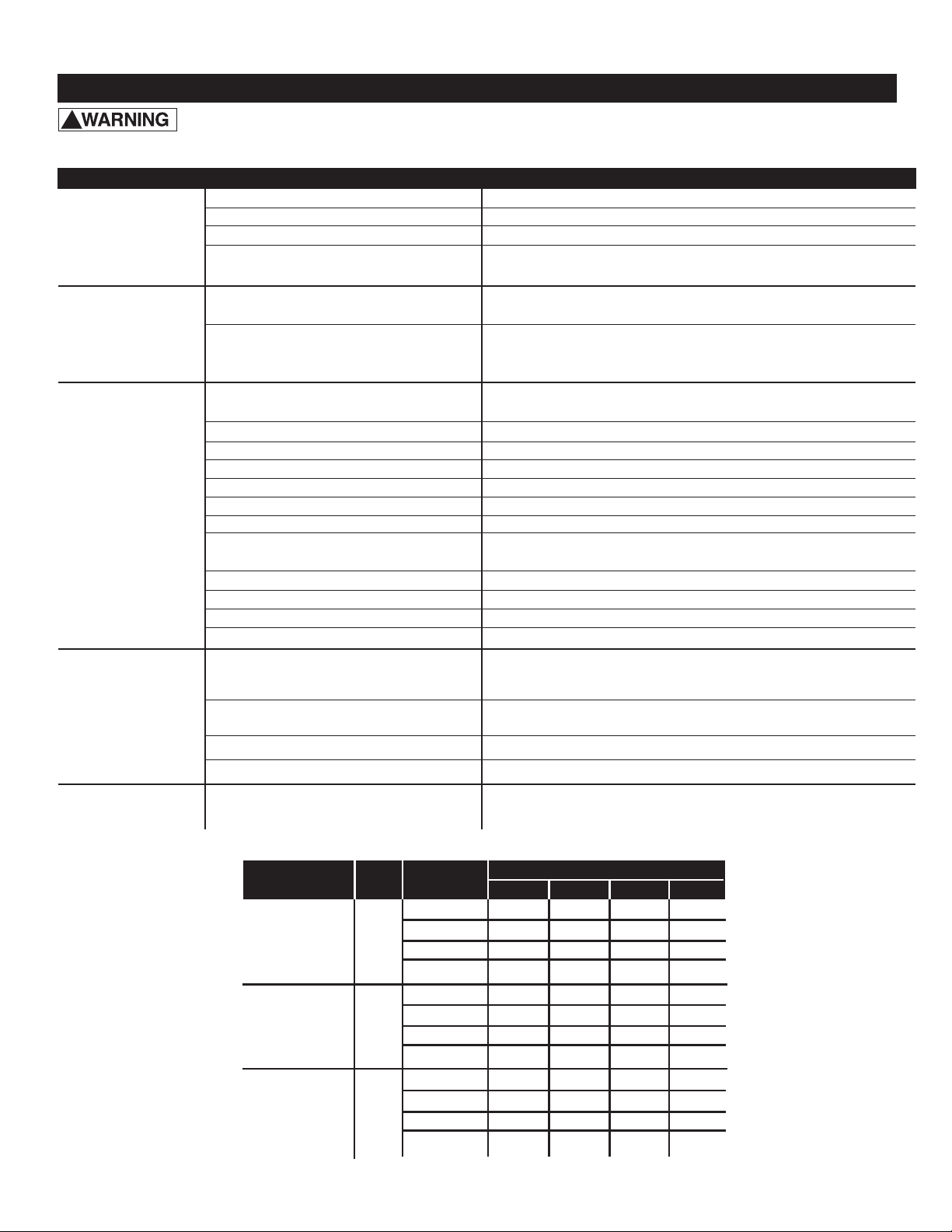
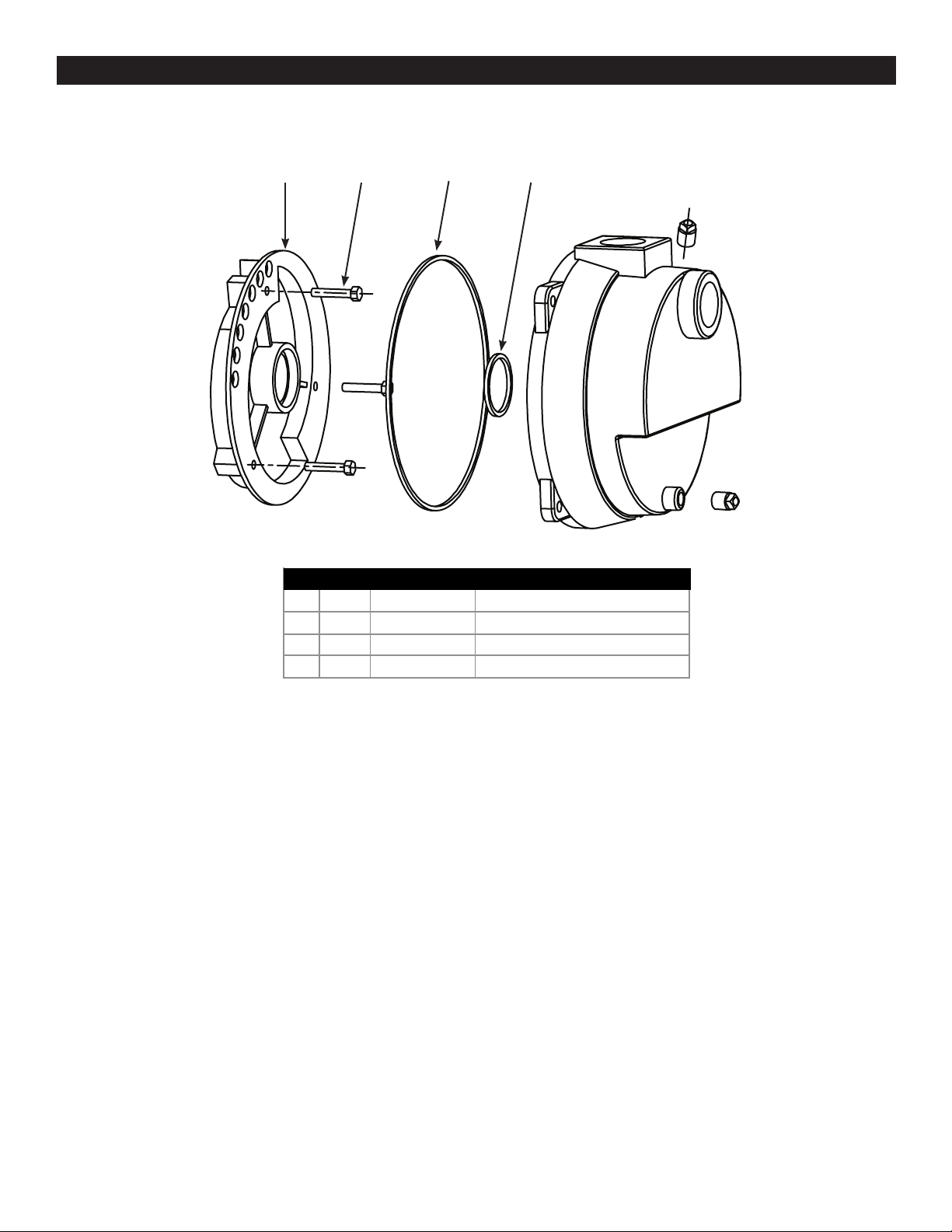
REPAIR PARTS
1234
NO. QUANTITY PART NUMBER DESCRIPTION
1 1 EFLS15007 O-Ring Diffuser
2 1 EFLS15008 O-Ring Housing
3 3 EFLS15009 Bolt
4 1 EFLS15005 Diffuser

10
WARRANTY
Retain Original Purchase Receipt for Warranty Eligibility
Limited Warranty
Manufacturer warrants to the original consumer purchaser (“Purchaser” or “You”) that its products are free from defects in
material and workmanship for a period of twelve (12) months from the date of the original consumer purchase. If, within
twelve (12) months from the original consumer purchase, any such product shall prove to be defective, it shall be repaired
or replaced at manufacturer’s option, subject to the terms and conditions set forth herein. Note that this limited warranty
applies to manufacturing defects only and not to ordinary wear and tear. All mechanical devices need periodic parts and
service to perform well. This limited warranty does not cover repair when normal use has exhausted the life of a part or
the equipment.
The original purchase receipt and product warranty information label are required to determine warranty eligibility. Eligibil-
ity is based on purchase date or original product – not the date of replacement under warranty. The warranty is limited to
repair or replacement of original purchased product only, not replacement product (i.e. one warranty replacement allowed
per purchase).
Purchaser pays all removal, installation, labor, shipping, and incidental charges.
Claims made under this warranty shall be made by contacting and returning the product to the factory immediately after
the discovery or any alleged defect. Manufacturer will subsequently take corrective action as promptly as reasonably pos-
sible. No requests for service will be accepted if received more than 30 days after the warranty expires. Warranty is not
transferable and does not apply to products used in commercial/rental applications.
General Terms and Conditions; Limitations of Remedies
You must pay all labor and shipping charges necessary to replace product covered by this warranty. This warranty does
not apply to the following: (1) acts of God; (2) products which, in manufacturer’s sole judgment, have been subject to
negligence, abuse, accident, misapplication, tampering, or alteration; (3) failures due to improper installation, operation,
maintenance or storage; (4) atypical or unapproved application, use or service; (5) failures caused by corrosion, rust or
other foreign materials in the system, or operation at pressures in excess of recommended maximums.
This warranty sets forth manufacturer’s sole obligation and purchaser’s exclusive remedy for defective products.
MANUFACTURER SHALL NOT BE LIABLE FOR ANY CONSEQUENTIAL, INCIDENTAL, OR CONTINGENT DAMAGES
WHATSOEVER. THE FOREGOING LIMITED WARRANTIES ARE EXCLUSIVE AND IN LIEU OF ALL OTHER EXPRESS
AND IMPLIED WARRANTIES, INCLUDING BUT NOT LIMITED TO IMPLIED WARRANTIES OF MERCHANTABILITY
AND FITNESS FOR A PARTICULAR PURPOSE. THE FOREGOING LIMITED WARRANTIES SHALL NOT EXTEND
BEYOND THE DURATION PROVIDED HEREIN.
Some states do not allow the exclusion or limitation of incidental or consequential damages or limitations on how long an
implied warranty lasts, so the above limitations or exclusions may not apply to You. This warranty gives You specic legal
rights and You may also have other rights which vary from state to state.
1899 Cottage Street
Ashland, Ohio 44805
Telephone: 1-844-394-2604