Loading ...
Loading ...
Loading ...
3
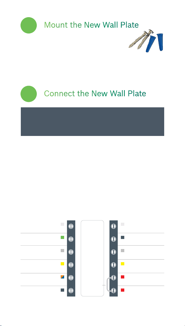
Feed all wires vertically into the hole or slit in the center
of the backplate. Referencing the photo of the previous
wiring configuration or the wire labels currently on the
wires, insert the wires one-by-one into the matching
terminals, and use the supplied flathead screwdriver to
close each terminal. After you have finished fastening the
wires, pull each wire gently to ensure they are secure.
Repeat this process for each wire to be installed.
Connect the New Wall Plate
3
CAUTION: To prevent possible shorts to adjacent
terminals, use care when securing and routing
your thermostat wires.
Mount the New Wall Plate
Use the enclosed screws and anchors to
mount the new wall plate. In most cases,
you can utilize the same mounting position of your old
thermostat. Be sure to check the alignment of your wall
plate before installation to ensure all holes are covered.
2
Note: The color of your wires may not be the same as shown in this User Guide
(1)Emergency heat activated at W1, (2)Auxiliary heat activated at W2,
(3)Only to be used with Bosch WSHP)
BCC100 Terminal Key
Data
Alarm Input
3
C
Common
W/E (W1)
1st Stage Heating
1
Y (Y1)
1st Stage Compressor
RH
Heating Appliance Power
RC (R)
Cooling Appliance Power
----
Not Used
G
Fan
W2
(W2) 2nd Stage Heating
2
Y2
2nd Stage Compressor
O/B
Reversing Valve
H/DH
Humidifier/Dehumidifier
Jumper
Loading ...
Loading ...
Loading ...