Version 09/05 - Page 1
NOVA
Wall Mount Canopy Rangehood
• Installation Instructions
• Use and Care Information
READ AND SAVE THESE INSTRUCTIONS
The Installer must leave these instructions with the homeowner.
The homeowner must keep these instructions for future reference
and for local electrical inspectors' use.
READ THESE INSTRUCTIONS BEFORE YOU START INSTALLING THIS RANGEHOOD
WARNING: - TO REDUCE THE RISK OF A RANGE TOP GREASE FIRE: a) Never leave surface units unattended at high
settings. Boilovers cause smoking and greasy spillovers that may ignite. Heat oils slowly on low or medium setting. b)
Always turn hood ON when cooking at high heat or when flambeing food (i.e. Crepes Suzette, Cherries Jubilee, Pepper-
corn Beef Flambé). c) Clean ventilating fans frequently. Grease should not be allowed to accumulate on fan or filter. d)
Use proper pan size. Always use cookware appropriate for the size of the surface element.
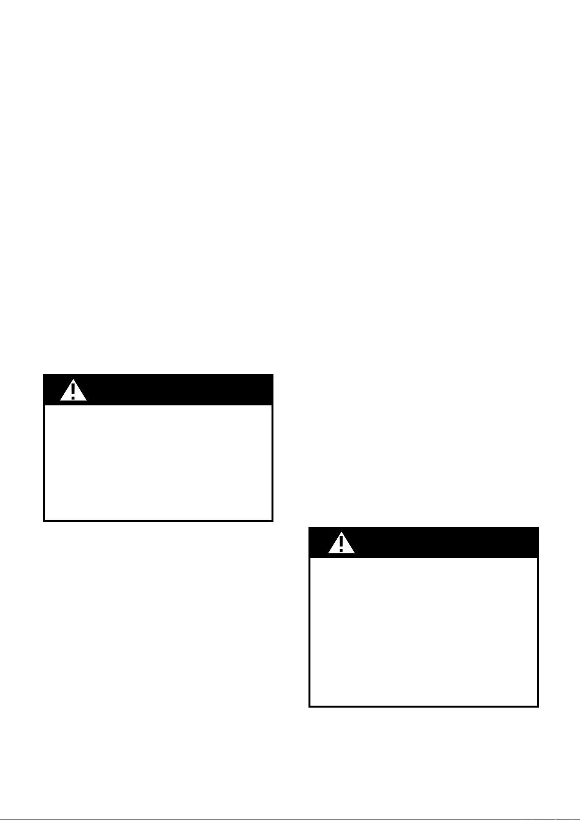
WARNING: - TO REDUCE THE RISK OF INJURY TO PERSONS IN THE EVENT OF A RANGE TOP GREASE FIRE, OBSERVE
THE FOLLOWING: SMOTHER FLAMES with a close-fitting lid, cookie sheet, or metal tray, then turn off the burner. BE
CAREFUL TO PREVENT BURNS. If the flames do not go out immediately EVACUATE AND CALL THE FIRE DEPARTMENT.
NEVER PICK UP A FLAMING PAN - You may be burned. DO NOT USE WATER, including wet dishcloths or towels - a
violent steam explosion will result. Use an extinguisher ONLY if: 1. You know you have a Class ABC extinguisher, and
you already know how to operate it. 2. The fire is small and contained in the area where it started. 3. The fire department
is being called. 4. You can fight the fire with your back to an exit.
ALL WALL AND FLOOR OPENINGS WHERE THE RANGEHOOD IS INSTALLED MUST BE SEALED.
This rangehood requires at least 24" of clearance between the bottom of the rangehood and the cooking surface or countertop.
This minimum clearance may be higher depending on local building code. For example, for gas ranges, a minimum of 30" may
be required. The maximum depth of overhead cabinets is 13". Overhead cabinets on both sides of this unit must be a minimum
of 18" above the cooking surface or countertop. Consult the cooktop or range installation instructions given by the manufacturer
before making any cutouts. MOBILE HOME INSTALLATION The installation of this rangehood must conform to the Manufactured
Home Construction and Safety Standards, Title 24 CFR, Part 3280 (formerly Federal Standard for Mobile Home Construction and
Safety, Title 24, HUD, Part 280). Four wire power supply must be used and the appliance wiring must be revised. See Electrical
Requirements.
LISEZ BIEN CETTE FICHE AVANT D'INSTALLER LA HOTTE
AVERTISSEMENT - POUR MINIMISER LE RISQUE DʼUN FEU DE GRAISSE SUR LA TABLE DE CUISSON : a) Ne jamais laisser
un élément de la table de cuisson fonctionner sans surveillance à la puissance de chauffage maximale; un renversement/
débordement de matière graisseuse pourrait provoquer une inflammation et le génération de fumée. Utiliser toujours une
puissance de chauffage moyenne ou basse pour le chauffage dʼhuile. b) Veiller à toujours faire fonctionner le ventilateur
de la hotte lors dʼune cuisson avec une puissance de chauffage élevée ou lors de la cuisson dʼun mets à flamber (i.e.
Crepes Suzette, Cherries Jubilee, Peppercorn Beef Flambé). c) Nettoyer fréquemment les ventilateurs dʼextraction. Veiller
à ne pas laisser de la graisse sʼaccumuler sur les surfaces du ventilateur ou des filtres. d) Utiliser toujours un ustensile
de taille appropriée. Utiliser toujours un ustensile de taille adapté à la taille de lʼélément chauffant.
AVERTISSEMENT: - POUR PRÉVENIR LES BLESSURES EN CAS DE FEU SUIVRE LES RECOMMANDATIONS SUIVANTES:
ÉTOUFFEZ LE FEU avec un couvercle métallique et fermez le brûleur. Si le feu ne s'éteint pas tout de suite, QUITTEZ
LES LIEUX ET APPELEZ LES POMPIERS. NE TOUCHEZ JAMAIS UNE CASSEROLE EN FLAMMES. N'UTILISEZ JAMAIS
DE L'EAU ou un torchon mouillé pour éteindre le feu - ce qui pourrait causer une explosion de vapeur. N'utilisez un
extincteur que si: 1. Vous avez un modèle ABC et vous connaissez bien son mode d'emploi. 2. Le feu est petit et peu
répandu. 3. Les pompiers sont déjà prévenus. 4. Vous avez une sortie derrière vous.
TOUTE OUVERTURE DANS LE MUR OU LE PLANCHER À PROXIMITÉ DE LA HOTTE DOIT ÊTRE SCELLÉ
Gardez 24 po. de hauteur entre le bas de la hotte et la surface de cuisson. Cette hauteur minimum peut être plus haute suivant le
code municipal. Par exemple, les cuisinières à gaz peuvent requérir 30 po. de hauteur. Les armoires au-dessus ne dépasseront
pas 13 po. de profondeur. Les armoires au-dessus de chaque côté devront être au moins à 18 po. au-dessus de la surface
de cuisson. Consultez la fiche technique avant de découper les armoires. L'installation de cette hotte doit être conforme aux
Réglements de Manufactured Home Construction and Safety Standards, titre 24 CFR, Section 3280 (anciennement Federal
Standard for Mobile Home Construction and Safety Standards, titre 24 CFR, Section 3280 (anciennement Federal Standard for
Mobile Home Construction and Safety, titre 24, HUD, Section 280). Le branchement électrique se fait avec une raccordement à
4 fils. Consultez la fiche technique électrique.
Version 09/05 - Page 2
VENTING REQUIREMENTS
Determine which venting method is best for your application.
Ductwork can extend either through the wall or the roof.
The length of the ductwork and the number of elbows should
be kept to a minimum to provide efficient performance. The
size of the ductwork should be uniform. Do not install two
elbows together. Use duct tape to seal all joints in the ductwork
system. Use caulking to seal exterior wall or floor opening
around the cap.
Flexible ductwork is not recommended. Flexible ductwork
creates back pressure and air turbulence that greatly
reduces performance.
Make sure there is proper clearance within the wall or floor
for exhaust duct before making cutouts. Do not cut a joist or
stud unless absolutely necessary. If a joist or stud must be
cut, then a supporting frame must be constructed. For best
results, remote blowers should transition to 9" round duct
as soon as possible. If small ducting is used, it should be
transitioned to 9" round as soon as possible.
FOR MORE SPECIFIC DUCTWORK INFORMATION, GO
TO PAGE 5.
WARNING - To Reduce The Risk Of Fire, Use Only Metal
Ductwork.
This appliance should be connected directly to the fused
disconnect (or circuit breaker) through flexible, armored or
nonmetallic sheathed copper cable. Allow some slack in the
cable so the appliance can be moved if servicing is ever nec-
essary. A UL Listed, 1/2" conduit connector must be provided
at each end of the power supply cable (at the appliance and
at the junction box).
When making the electrical connection, cut a 1 1/4" hole
in the wall. A hole cut through wood must be sanded until
smooth. A hole through metal must have a grommet.
SUITABLE FOR USE WITH SOLID STATE SPEED CON-
TROLS.
WARNING - TO REDUCE THE RISK OF FIRE, ELECTRI-
CAL SHOCK, OR INJURY TO PERSONS, OBSERVE THE
FOLLOWING: Use this unit only in the manner intended
by the manufacturer. If you have any questions, contact
the manufacturer.
Before servicing or cleaning unit, switch power off at
service panel and lock the service disconnecting means
to prevent power from being switched on accidentally.
When the service disconnecting means cannot be locked,
securely fasten a prominent warning device, such as a
tag, to the service panel.
WARNING - TO REDUCE THE RISK OF SHOCK: This fan
must be installed with an isolating wall control/switch.
CAUTION: For General Ventilating Use Only. Do Not
Use To Exhaust Hazardous or Explosive Materials and
Vapors.
WARNING - TO REDUCE THE RISK OF FIRE, ELECTRI-
CAL SHOCK, OR INJURY TO PERSONS, OBSERVE THE
FOLLOWING: Installation Work And Electrical Wiring Must
Be Done By Qualified Person(s) In Accordance With All
Applicable Codes And Standards, Including Fire-Rated
Construction.
Sufficient air is needed for proper combustion and
exhausting of gases through the flue (chimney) of fuel
burning equipment to prevent backdrafting. Follow the
heating equipment manufacturer's guideline and safety
standards such as those published by the National Fire
Protection Association (NFPA), and the American Society
for Heating, Refrigeration and Air Conditioning Engineers
(ASHRAE), and the local code authorities.
When cutting or drilling into wall or ceiling, do not dam-
age electrical wiring and other hidden utilities.
Ducted fans must always be vented to the outdoors.
• Electrical ground is required on this rangehood.
• If cold water pipe is interrupted by plastic,
nonmetallic gaskets or other materials, DO NOT
use for grounding.
• DO NOT ground to a gas pipe.
• DO NOT have a fuse in the neutral or grounding
circuit. A fuse in the neutral or grounding circuit
could result in electrical shock.
• Check with a qualified electrician if you are in doubt
as to whether the rangehood is properly grounded.
• Failure to follow electrical requirements may result
in a fire.
WARNING
ELECTRICAL REQUIREMENTS
A 120 volt, 60 Hz AC-only electrical supply is required on a
separate 15 amp fused circuit. A time-delay fuse or circuit
breaker is recommended. The fuse must be sized per local
codes in accordance with the electrical rating of this unit as
specified on the serial/rating plate located inside the unit
near the field wiring compartment. THIS UNIT MUST BE
CONNECTED WITH COPPER WIRE ONLY. Wire sizes
must conform to the requirements of the National Electrical
Code, ANSI/NFPA 70 - latest edition, and all local codes and
ordinances. Wire size and connections must conform with the
rating of the appliance. Copies of the standard listed above
may be obtained from:
National Fire Protection Association
Batterymarch Park
Quincy, Massachusetts 02269
• Venting system MUST terminate outside the
home.
• DO NOT terminate the ductwork in an attic or
other enclosed space.
• DO NOT use 4" laundry-type wall caps.
• Flexible-type ductwork is not recommended.
• DO NOT obstruct the flow of combustion and
ventilation air.
• Failure to follow venting requirements may result
in a fire.
WARNING
For residential use only.
!
!
Version 09/05 - Page 3
RÈGLEMENTS D'ÉVACUATION
Confirmer la sortie d'évacuation - soit par le mur, soit par
le toit.
Utilisez une longueur de tuyauterie minimale avec les moindres
de coudes pour la plus grande efficacité. Le diamètre de
tuyauterie doit être uniforme. N'installez jamais 2 coudes
ensemble. Scellez bien tous les joints avec un ruban adhésif
métallique à l'intérieur et scellez bien le clapet extérieur avec
du calfeutrage.
Utilisez un tuyau d'évacuation rigide lorsque possible.
Un tuyau flexible égale deux fois plus qu'un tuyau rigide,
ce qui réduit la puissance d'évacuation. Un conduit
d'évacuation flexible crée une contre-pression et une
turbulence de l'air qui réduisent considérablement la
performance.
Veillez à ce que l'espace pour le tuyau soit ample - ainsi on
n'aurait pas besoin de découper les supports de mur intérieur.
Si ce découpage est nécessaire, veillez bien à ce qu'un
renforcement soit mis en place.
Pour de meilleurs résultats, utilisez un tuyau de transition de
9 pouces dès que possible.
RÈGLEMENTS D'ÉVACUATION ADDITIONELL -
PAGE 9.
AVERTISSEMENT - Pour Ne Pas Risquer Un Feu, Utilisez
Seulement Les Matériaux Métalliques.
A utiliser avec un dispositif de reglage de vitesse a semi-
conducteurs.
AVERTISSEMENT – POUR MINIMISER LES RISQUES
DʼINCENDIE, CHOC ÉLECTRIQUE OU DOMMAGES
CORPORELS, OBSERVER LES PRESCRIPTIONS
SUIVANTES: Suivez les recommandations du fabricant
et entre en communication avec lui pour toute
information.
Fermez le courant avant tout entretien et veillez a ce qu'il
reste fermé. Si on ne peut pas verrouiller le panneaux
du service électrique, affichez un avis de danger sur la
porte.
AVERTISSEMENT – POUR MINIMISER LE RISQUE DE
CHOC ÉLECTRIQUE: Ce ventilateur doit être installé avec
un mur d'isolement iterrupteur de commande.
AVIS: Pour L'évacuation Générale - Veillez à Ne Pas
Evacuer Des Matériaux Ou Vapeurs Explosif.
AVERTISSEMENT – POUR MINIMISER LES RISQUES
DʼINCENDIE, CHOC ÉLECTRIQUE OU DOMMAGES
CORPORELS, OBSERVER LES PRESCRIPTIONS
SUIVANTES: L'installation Et Le Raccordement Electrique
Doivent Se Faire Par Un Technicien Qualifié Selon Tous
Les Codes Municipaux.
Afin d'obtenir un rendement maximal en ce qui a trait à la
combustion ainsi qu'à l'évacuation des gaz par la conduite
de cheminée, une bonne aération est nécessaire pour
tous les appareils à combustion. Suivez les conseils et
mesures de sécurité du fournisseur tels que ceux publiés
par l'Association Nationale de la Sauvegarde contre
l'Incendie et l'Association Américaine d'Ingénieurs de
Chauffage, Frigorifaction et Air Climatisé ainsi que les
codes municipaux.
En perçant un mur veillez à ne pas perforer un autre fil
électrique.
Une ventilateur à évacuation extérieure doit être raccordée
à l'extérieur.
AVERTISSEMENT
• Le système d'évacuation DOIT sortir à l'extérieur.
• N'ÉVACUEZ PAS le conduit soit dans une
mansarde soit dans un espace enfermé.
• N'UTILISEZ PAS un clapet de séchoir à 4 pouces.
• N'utilisez pas un conduit flexible.
• N'ENCOMBREZ PAS la circulation d'air.
• Faute de suivre cet avertissement pourrait
occasionner un feu.
FICHE TECHNIQUE ÉLECTRIQUE
Le raccordement électrique doit se faire avec un circuit séparé
de 15 ampères fusible à 120V, 60 Hz, courant alternant. On
recommande un coupe-circuit. La taille du fusible doit se
conformer aux codes municipaux suivant la spécification
électrique sur la plaque intérieure. Le diamètre du fil
devra aussi se conformer aux règlements du code national
électrique, ANSI/NFPA 70 - ainsi qu'aux règlements locaux
et les spécifications de cet appareil. On peut obtenir ces
informations chez:
l'Association Nationale de la Prévention du Feu
Batterymarch Park
Quincy, Massachusetts 02269
Raccordez cet appareil directement au coupe-circuit avec un fil
flexiblle couvert en cuivre en laissant un peu de lâchement dans
le fil pour permettre le déplacement de l'appareil. Veillez a ce
qu'un contact d'un demi-pouce (1/2 po.) soit installé à chaque
bout de fil (soit à l'appareil ainsi qu'à la boite à fusible).
Faites un trou de 1 1/4 po. dans le mur. S'il s'agit d'un trou en
bois - sablez-le bien, tandis qu'un trou passant par le métal
demande un bouche-trou.
• Une prise à terre est nécessaire pout cette hotte.
• N'utilisez pas un tuyau à l'eau froide pour la mise
à terre s'il est branché à un joint plastique, non-
métallique ou autre.
• NE JOIGNEZ PAS la mise à terre à conduit de gaz.
• N'INSTALLEZ PAS un fusible dans le circuit de
mise à terre - ce qui peut causer une secousse
électrique.
• Vérifiez avec un électricien certifié à ce que la hotte
soit bien mise à terre.
• Faute de suivre ces recommandations pourrait
occasionner un feu.
AVERTISSEMENT
Uniquement pour usage menager.
!
!
Version 09/05 - Page 4
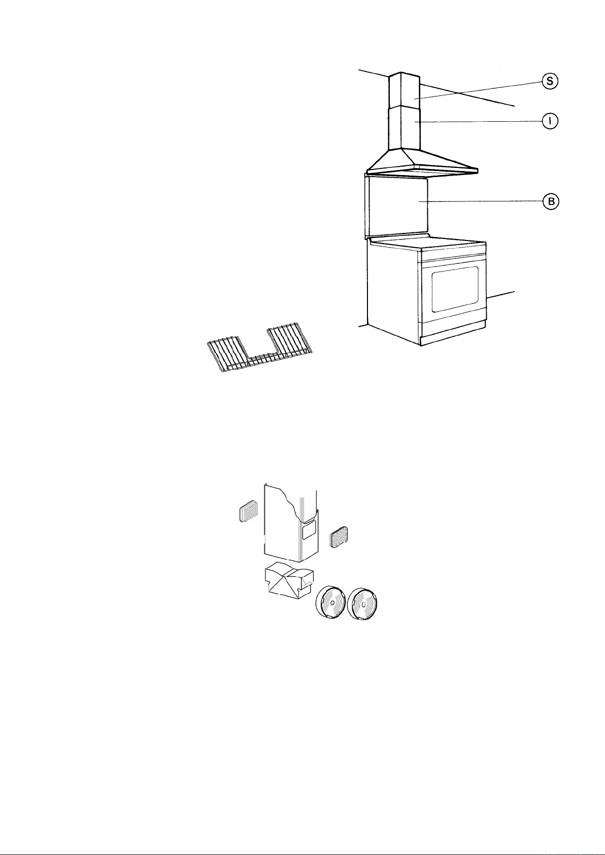
Includes attachments for mounting to cabinets on both sides
Wire Rack/Tablette de Rangement
30 Chrome
36 Chrome
For mounting wire rack to back wall if
there are no cabinets to attach rack to.
Wire Rack Hanger Kit/Support Pour Tablettes de Rangement
Chrome
6099970
6095040
6099920
Includes: • Lower Chimney with holes for ducting • Ductless
Diverter • Vent Grates • Two Charcoal Filters
Ductless Conversion Kit/
Kit Pour Conversion Du Conduit
Stainless
White
Black
6097110
6097111
6097112
Replacement Charcoal Filters/Filtres au Charbon
6093034
High Ceiling Chimney Kit/
Kit D'extension Pour La Cheminée Plafond Haut
One 40” upper chimney (S) to replace 20” up-
per chimney (S) that came with hood
Stainless 6099757
OPTIONAL ACCESSORIES AVAILABLE/ACCESSOIRES POUR LʼINSTALLATION
(B) 24" high, mounts to the wall beneath
the rangehood for a coordinated look
24" High Backsplash/Dosseret 24 po
30 x 24 Stainless
36 x 24 Stainless
6098835
6098815
(B) 30" high, mounts to the wall beneath
the rangehood for a coordinated look
30" High Backsplash/Dosseret 30 po
30 x 30 Stainless
36 x 30 Stainless
620000095
620000096
Version 09/05 - Page 5
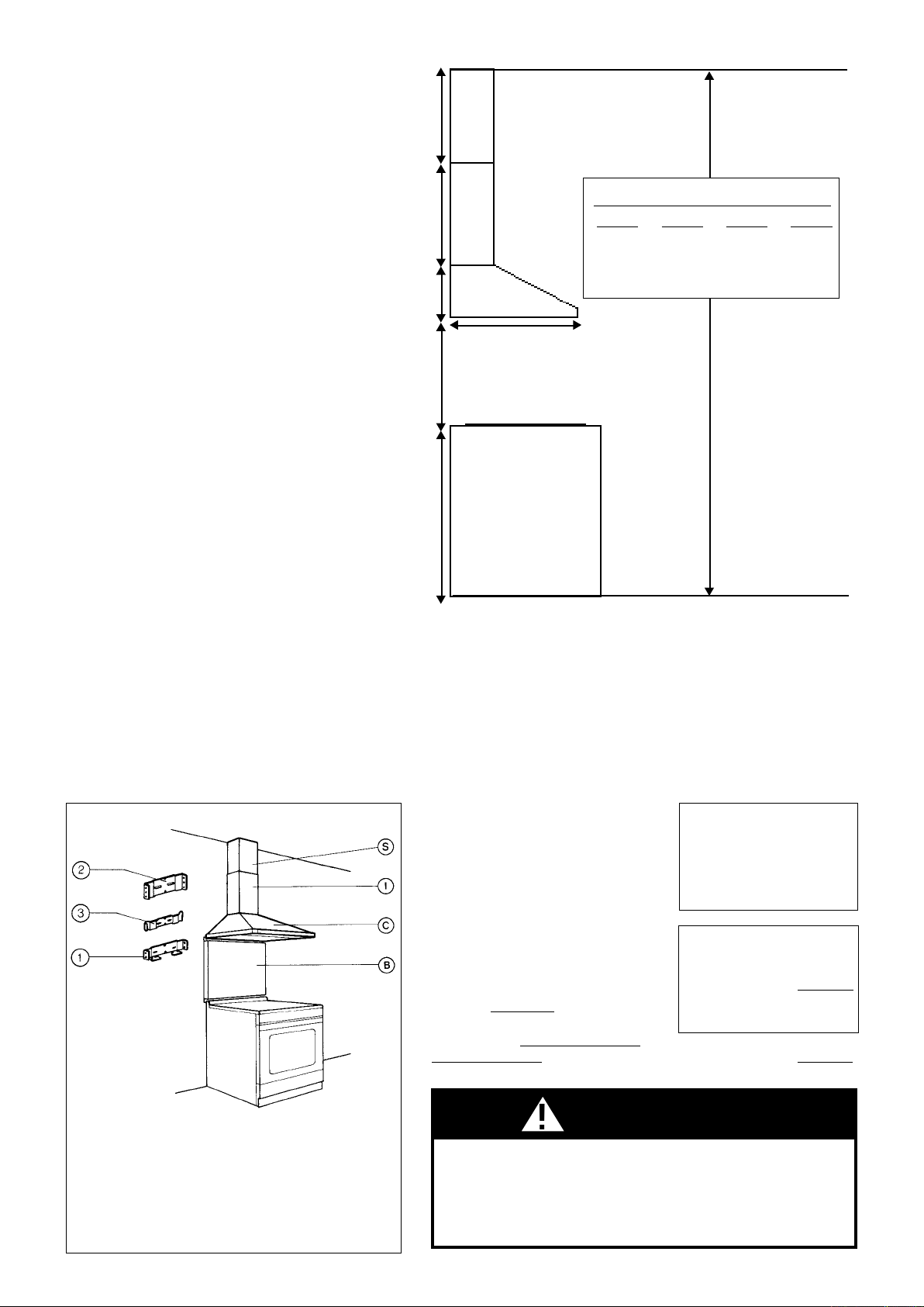
PLAN THE INSTALLATION
The Nova chimneys
are adjustable and
designed to meet
varying ceiling heights
as indicated in FIGURE
2. The chimneys
can be adjusted for
ceilings between 7'
8 1/2" and 9' 9 1/2"
depending on the
distance between the
bottom of the hood and
the cooktop (distance
x in FIGURE 2).
TOOLS NEEDED FOR INSTALLATION
• Saber Saw or Jig Saw
• Drill
• 1 1/4" Wood Drill Bit
• Pliers
• Phillips Screwdriver
• Flat Blade Screwdriver
• Wire Stripper or Utility Knife
• Metal Snips
• Measuring Tape or Ruler
• Level
• Pencil
• Caulking Gun
• Duct Tape
PARTS SUPPLIED FOR INSTALLATION
• 1 Hardware Package
• 1 Literature Package
PARTS NEEDED FOR INSTALLATION
• 2 Conduit Connectors
• Power Supply Cable
• Wiring Cable - Optional Remote Blower Only
• 1 Wall or Roof Cap
• All Metal Ductwork
RANGEHOOD ASSEMBLY
B -
C -
S -
I -
1 -
2 -
3 -
OPTIONAL BACKSPLASH
CANOPY
UPPER CHIMNEY
LOWER CHIMNEY
CANOPY MOUNTING BRACKET
UPPER CHMINEY BRACKET
MIDDLE CHIMNEY BRACKET
FIGURE 1
For best results, use no more than
three 90° elbows. Make sure that
there is a minimum of 24" of straight
duct between elbows if more than
one is used. Do not install two
9 Feet Straight Duct
2 - 90˚ Elbows
Wall Cap
Total System
9.0 feet
10.0 feet
0.0 feet
19.0 feet
FIGURE 4
3.0 feet
5.0 feet
12.0 feet
0.0 feet
45˚ Elbow
90˚ Elbow
90˚ Flat Elbow
Wall Cap
FIGURE 3
PLAN THE INSTALLATION
This rangehood can be installed as either ducted
or ductless. The blower can be vented through the
wall or ceiling. To vent through a wall, a 90° elbow is
used. When installed ductless, the rangehood vents
out of grates on the sides of the chimney. Ductless
installations require a Ductless Conversion Kit,
available from your dealer.
This rangehood can be used with an optional remote
blower. If a remote blower is used, then the internal
blower must be removed and discarded. Both blowers
cannot be used together. The remote blower connects
to the rangehood using a separate wiring cable not
supplied with the rangehood. The wiring cable should
be installed at the same time as the ductwork.
WARNING! BEFORE MAKING ANY CUTS OR
HOLES FOR INSTALLATION, DETERMINE WHICH
VENTING METHOD WILL BE USED AND CAREFULLY
CALCULATE ALL MEASUREMENTS.
CALCULATE THE DUCTRUN LENGTH
The ductrun should not exceed 35 equiva-
lent feet if ducted with the required minimum
of 3 1/4" by 10" rectangular duct and 55
equivalent feet if ducted with 9" round duc-
twork (Remote blowers require 9" round
duct). Calculate the length of the ductwork
by adding the equivalent feet in FIGURE
3 for each piece of duct in the system An
example is given in FIGURE 4.
upper
chimney
lower
chimney
canopy
x = distance from hood to cooktop
(varies depending on installation)
min - 24”, suggested max - 30”
cabinet base
1” min
20” max
22”
9 1/2”
36”
FIGURE 2
19 1/4”
x
also consult cooktop
manufacturer's recommendation
elbows together. If you must elbow right away, do it as far away
from the hood's exhaust opening as possible.
WARNING
Because of the weight and size of the rangehood canopy, two or
more people are needed to move and safely install the rangehood
canopy. Failure to properly lift rangehood could result in damage
to the product or personal injury.
PERSONAL INJURY HAZARD
For shorter ceilings, have the chimney cover(s) cut at a sheet metal
shop. For higher ceilings, there are two extension kits available
depending on how much height is required. For very tall ceilings, the
Cathedral Chimney Kit includes a new 4ʼ upper chimney and a new
4ʼ lower chimney. For installations where only 1” - 20” of additional
height is needed, the High Ceiling Chimney Kit includes a new 40”
upper chimney which would replace the 20” upper chimney that came
with the hood.
min & max ceiling height examples
x = 30"
min
8' 2 1/2"
max
9' 9 1/2"
x = 28"
min
8' 1/2"
max
9' 7 1/2"
x = 26"
min
7' 10 1/2"
max
9' 5 1/2"
x = 24"
min
7' 8 1/2"
max
9' 3 1/2"
!
Version 09/05 - Page 6
3. Remove the cover from the field wiring compartment.
Remove the wiring electrical knockout using a flat-blade
screwdriver. Feed the Power Supply Cable through the
electrical knockout.
PREPARE THE WALL
1. Disconnect and move freestanding range from cabinet
opening to provide easier access to upper cabinet and rear
wall. Put a thick, protective covering over cooktop, set-in
range or countertop to protect from damage or dirt.
2. Determine and clearly mark with a pencil the center line
on the wall where the rangehood will be installed.
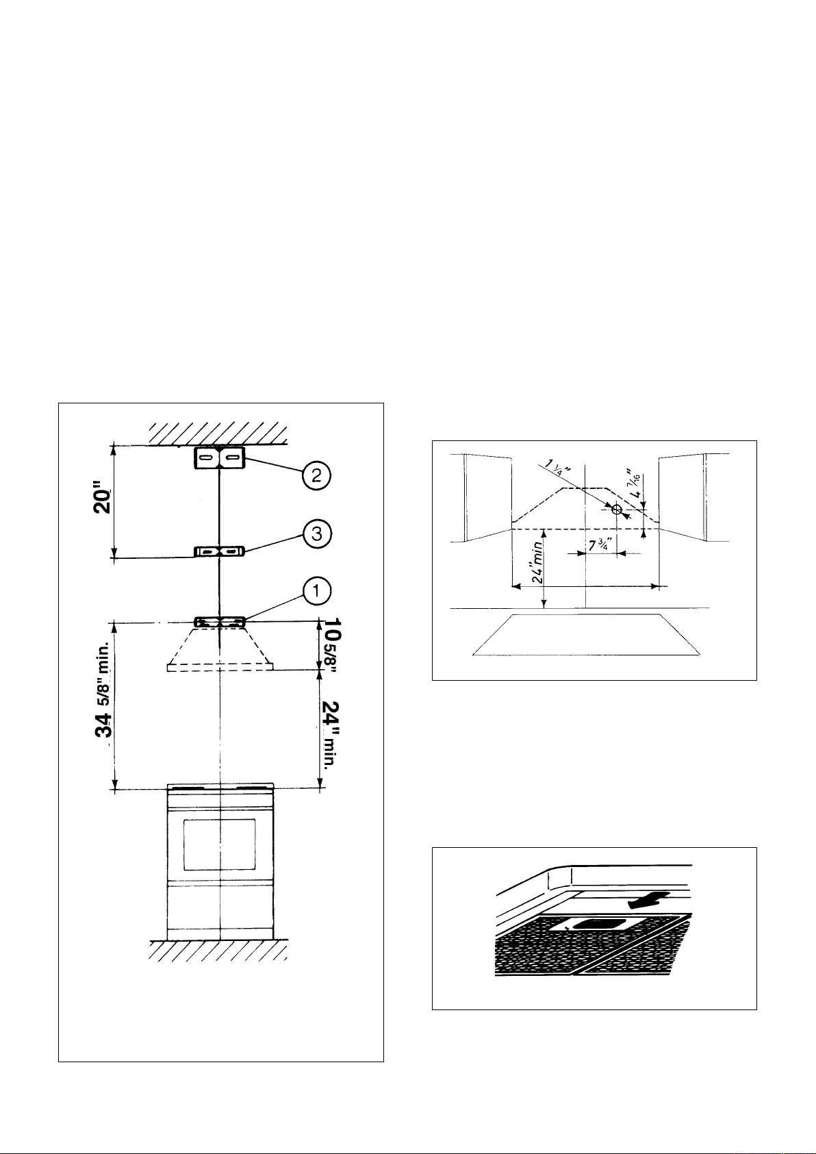
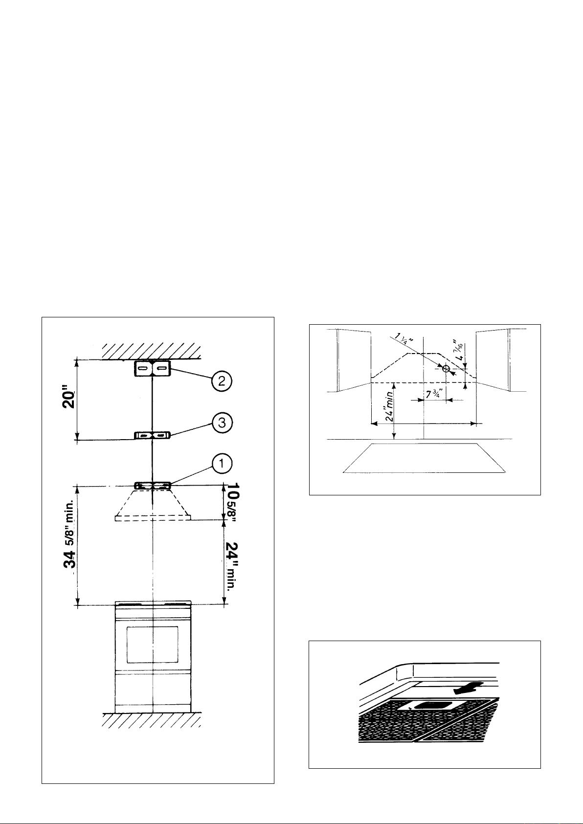
3. The Nova attaches to the wall by three mounting brackets,
points 1, 2 and 3 in FIGURE 5. The canopy of the rangehood
hangs from two metal flanges that extend from bracket 1. This
bracket must be mounted with the flanges on the bottom of
the bracket. The dimensions in FIGURE 5 are for mounting
the canopy 24" above the cooking surface.
If a Backsplash is to be used with this rangehood, it must
be installed before the rangehood. Installation instructions for
the backsplash are supplied in its box. The height of the
backsplash will determine the bottom edge of the canopy.
4. The chimney attaches to the wall by two additional
brackets, points 2 and 3 in FIGURE 5 which illustrates the
positioning of the chimney brackets. The largest bracket, 2,
should be installed about 1/8" away from the ceiling. The
middle bracket ( bright metal ) must be installed with the ends
touching the wall and the curves facing outward. The middle
bracket must be installed at the bottom point of the upper
chimney sleeve.
Determine the proper location for each bracket and install the
brackets on the wall. MAKE SURE THAT THE BRACKETS
ARE SECURELY FASTENED TO THE WALL.
5. Determine and make all necessary cuts in the wall for
the ductwork. Install the ductwork before the rangehood.
6. Determine the proper location for the Power Supply Cable
as indicated in FIGURE 6. Use a 1 1/4" Drill Bit to make this
hole. Run the Power Supply Cable. Use caulking to seal
around the hole. DO NOT turn on the power until installation
is complete. For remote blowers, a separate wiring cable is
required. DO NOT WIRE THE REMOTE BLOWER INTO
THE FIELD WIRING HOUSING OR CONNECT WITH THE
POWER SUPPLY CABLE.
INSTALL THE RANGEHOOD
FIGURE 7
1. Remove the unit from the carton and place on a flat
surface for assembly. Cover the surface to prevent accidental
damage. Remove all parts including the mounting hardware
before discarding the carton.
2. Remove the grease filters from the unit and set aside.
The grease filters are removed by pressing the handle in front
of the filter as indicated in FIGURE 7. When replacing, make
sure that the filters are properly positioned with the handles
in front and visible.
FIGURE 5
FIGURE 6
90 cm 35
3
/
8
" or 30"
Version 09/05 - Page 7
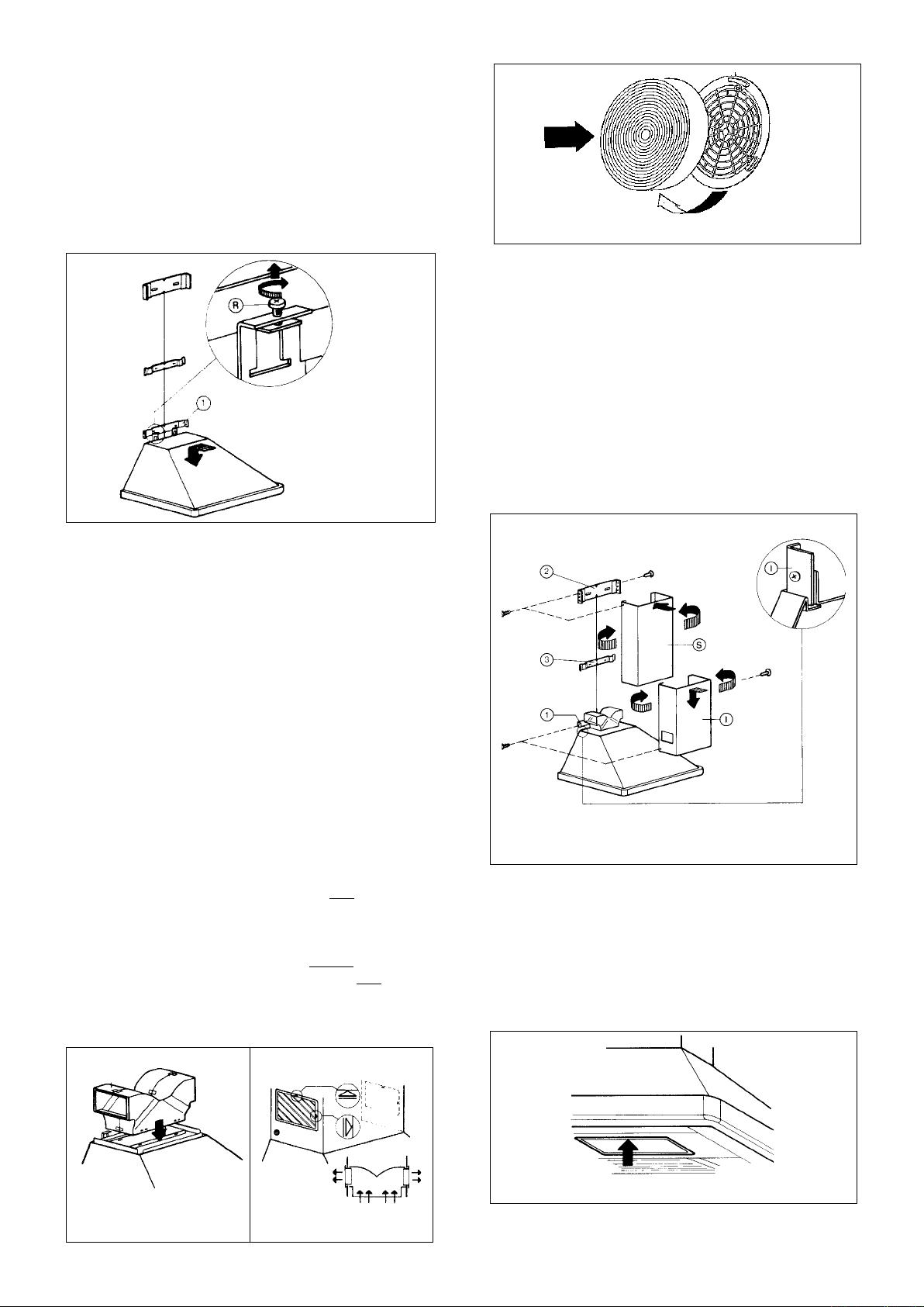
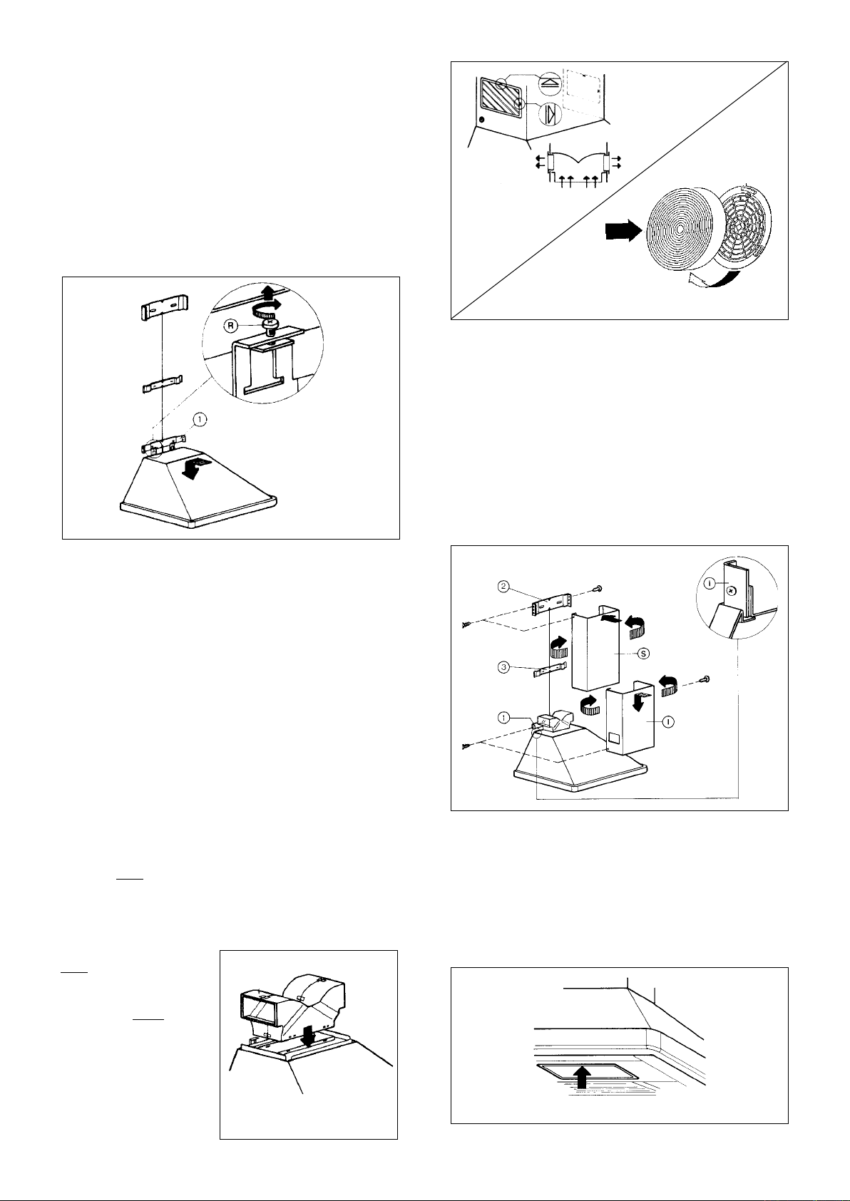
4. Rotate the two adjustment screws (R in FIGURE 8) until
inserted halfway in the slot. Hang the canopy on the bracket.
The canopy hangs from the flanges on the lower bracket. Due
to the weight of the canopy, two people should lift it to avoid
injuries. Make sure that the tabs are fully inserted into the
slots and that the canopy is secure on the bracket.
5. The height of the canopy can be adjusted by rotating
the two screws (R) indicated in FIGURE 8. These are also
used to insure that the canopy is level.
FIGURE 8
6. Connect the Power Supply Cable to the rangehood.
Attach the White lead of the power supply to the White lead
of the rangehood with a twist-on type wire connector. Attach
the Black lead of the power supply to the Black lead of the
rangehood with a twist-on type wire connector. Connect the
Green ( Green and Yellow ) ground wire under the Green
grounding screw.
7. If your installation uses a remote blower, connect the wir-
ing cable for the remote blower. DO NOT connect the remote
blower to the Power Supply Cable. The wiring diagram for this
rangehood is supplied next to the Use and Care Information
on the rear of the Installation Instructions.
8. Replace the field wiring compartment cover and the
grease filters
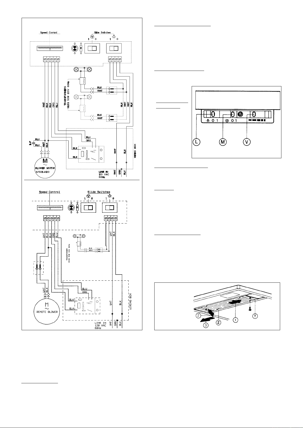
For ductless installations:
Ductless installations require a Ductless Conversion Kit.
This kit consists of a lower chimney cover with holes for the
exhaust air, a ductless diverter, two grids to cover the holes in
the chimney cover, two charcoal filters. The ductless diverter
must be installed before the lower chimney cover is attached as
in FIGURE 9. The lower chimney cover without holes should
be discarded. Once the lower chimney cover with holes is
installed, the grids are inserted into the holes as illustrated in
FIGURE 10. Attach the CHARCOAL FILTERS to both sides
of the blower (as indicated in FIGURE 11).
FIGURE 12
FIGURE 9 FIGURE 10
FIGURE 11
FIGURE 13
9. For ducted installations, the damper must be attached
to the exhaust opening on the top of the canopy. Two small
phillips screws are provided with the damper to attach it to
the canopy. Connect the ductwork and seal all connections
with duct tape.
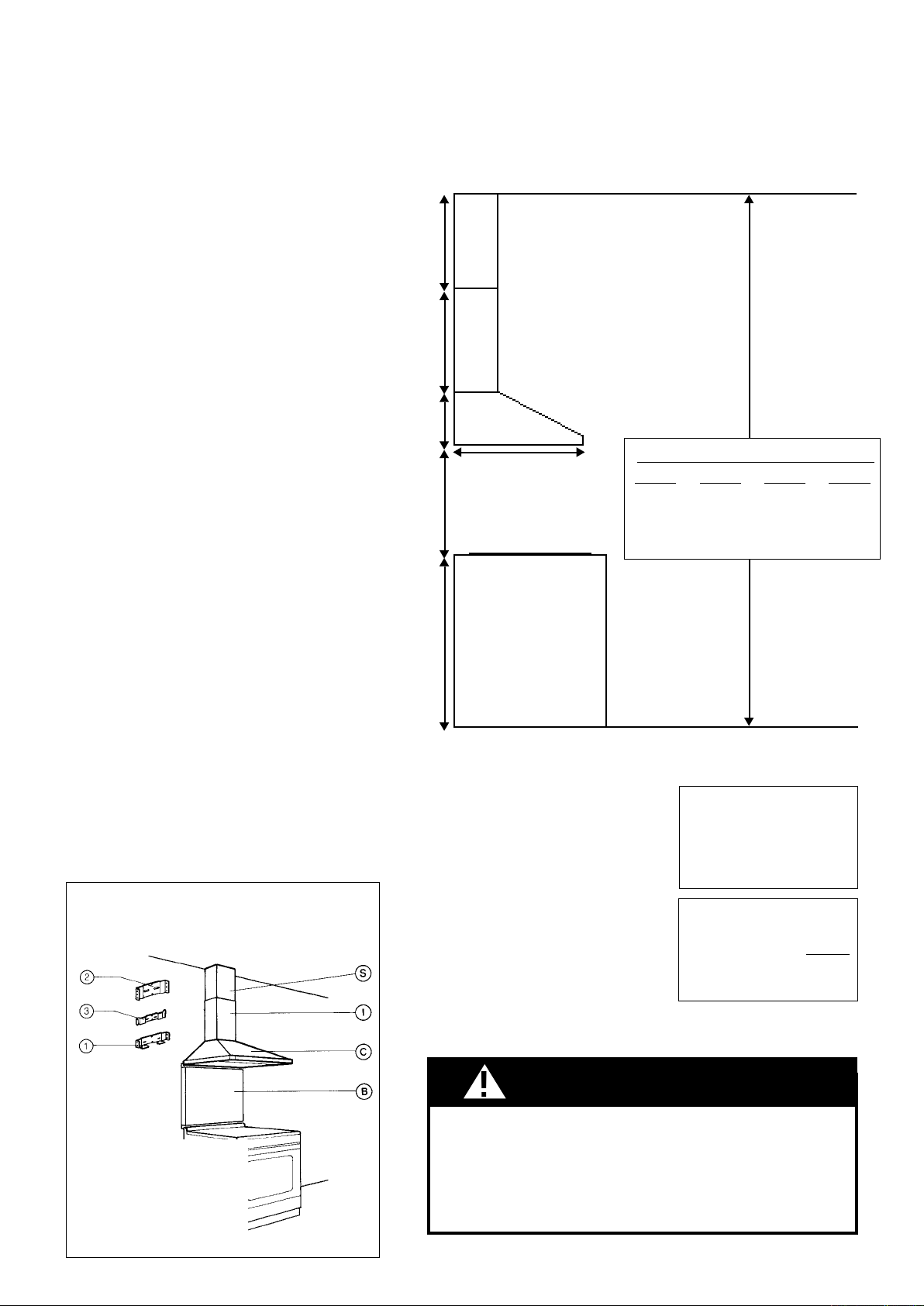
10. The chimney must be attached to the body of the range-
hood. The upper section of the chimney (S) must be installed
first, then the lower section (I). Both sections are secured to the
wall under the mounting brackets as indicated in FIGURE 12.
Once the chimney is in the final position, screws are used to
secure the top and bottom of the chimney to the brackets.
11. Turn the power supply on. Turn on blower and lights.
The rangehood controls are located in a gray panel on the
canopy's underside. To open the panel, press up on the
front edge and release as indicated in FIGURE 13. If the
rangehood does not operate, check that the circuit breaker
is not tripped or the house fuse blown. If the unit still does
not operate, disconnect the power supply and check that the
wiring connections have been made properly.
Version 09/05 - Page 8
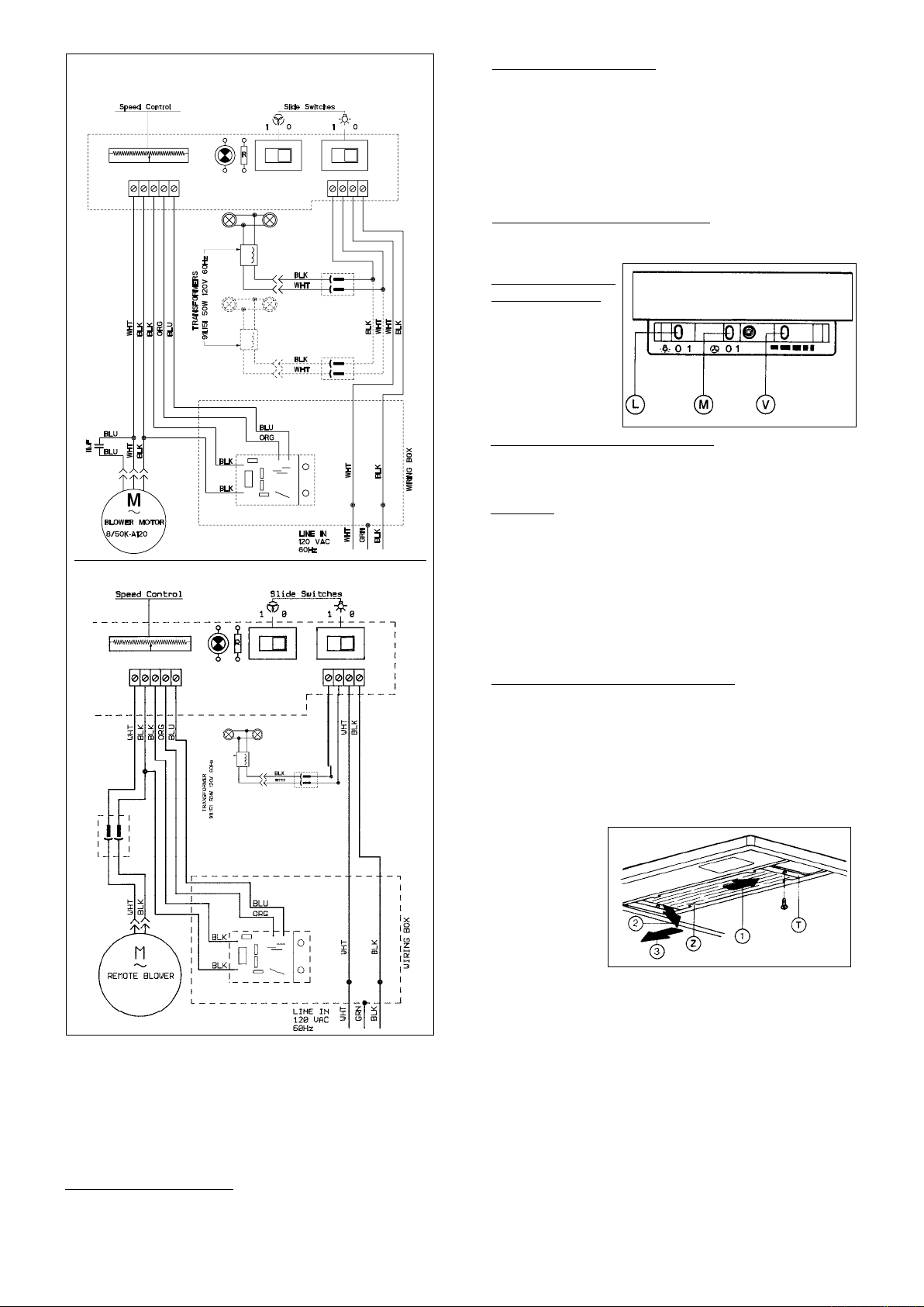
Blower Speed Button (V)
Variable speed control for blower. Move the switch to the far left
for LOW Speed and to the far right for HIGH speed.
Cleaning
The metal grease filters should be cleaned frequently in hot
detergent solution or washed in the dishwasher. Clean painted
hoods with hot soapy water. Stainless steel cleaner should be
used on stainless rangehoods. Abrasives and scouring agents
can scratch stainless steel finishes and should not be used to
clean finished surfaces.
Replacing the Lamps
Before replacing a lamp, turn off the lamp switch to prevent an
injury. To replace a halogen lamp (FIGURE 15), remove the
diffuser clips (T) on both ends of the stainless steel lamp panel.
Carefully slide the panel all the way to the right. Lower the left
end of the panel below the support flange (Z), then remove the
panel by sliding it back to the left. Remove the lamp by pressing
the bulb from the rear. Replace the bulb. Replace the lamp panel
by reversing these directions.
Rangehood Control Panel
The control panel, located on the right-hand side under the canopy,
is designed to disappear from view when not needed. To open,
press upward on the front edge and release. The panel will drop
into sight. To close, push upward on the bottom left corner of the
control panel and it will slide up into the hood. The position and
function of each control button is indicated in FIGURE 14.
Light On/Off Button (L)
On/Off switch for the halogen lights. Move the switch to "1" to
turn the lights ON and to "0" to turn them OFF.
FIGURE 14
WARRANTY & SERVICE
All Faber products are warranteed against any defect in materials or
workmanship for the original purchaser for a period of 1 year from the
date of original purchase. This warranty covers labor and replacement
parts. The warranty does not cover consumable parts such as filters
and light bulbs. This warranty does not apply if this product has been
subjected to faulty installation, misuse, or neglect. This warranty ex-
cludes any consequential expense or damage resulting from any use
or malfunction of the product. All implied warranties are limited to the
duration of this warranty.
To obtain warranty service, contact the dealer from whom you purchased
the rangehood, or the local Faber distributor. If you cannot identify a
local Faber distributor, contact us at (508) 358-5353 for the name of a
distributor in your area.
STANDARD INTERNAL BLOWER
WIRING DIAGRAMS
*AVAILABLE REMOTE BLOWER
* If a remote blower is used with this rangehood, current draw
must not exceed 4 amps.
• This rangehood uses 20 watt halogen lamps.
FIGURE 15
USE AND CARE INFORMATION
This rangehood system is designed to remove smoke,
cooking vapors and odors from the cooktop area.
For Best Results
Start the rangehood several minutes before cooking to
develop proper airflow. Allow the unit to operate for several
minutes after cooking is complete to clear all smoke and
odors from the kitchen.
Blower On/Off
Button (M)
On/Off switch
for the blower.
Move the switch
to "1" to turn the
blower ON and
to "0" to turn it
OFF.
Version 09/05 - Page 9
ASSEMBLAGE DE LA HOTTE
FIGURE 1
AVERTISSEMENT
9 pi de conduit droit
2 Coudes 90˚
Capuchon de mur
Système total
9,0 pi
10,0 pi
0,0 pi
19,0 pi
FIGURE 4
3,0 pi
5,0 pi
12,0 pi
0,0 pi
Coude 45˚
Coude 90˚
Coude plat 90˚
Capuchon de mur
FIGURE 3
OUTILS NÉCESSAIRES À LʼINSTALLATION
• Scie sauteuse ou à découper
• Perceuse
• Mèche à bois 1 1/4 po
• Pinces
• Tournevis Phillips
• Tournevis à lame plate
• Dénude fil ou couteau tout usage
• Pince coupante à fil métallique
• Ruban à mesurer ou règle
• Niveau
• Crayon
• Outil à calfeutrage
• Ruban à conduit
PIÈCES FOURNIES POUR LʼINSTALLATION
• 1 nécessaire de ferrures
• 1 nécessaire de documentation
PIÈCES NÉCESSAIRES POUR LʼINSTALLATION
• 2 connecteurs de conduit
• Câble dʼalimentation
• Câblage intérieur - pour ventilateur à
distance seulement
• 1 capuchon de mur ou de toit
• Conduit en métal
PLAN DE LʼINSTALLATION
Cette hotte peut être installée avec ou sans conduit.
La sortie dʼair peut sʼeffectuer par le mur ou le plafond.
Pour une ventilation par le mur, un coude 90
o
est
utilisé. Lorsque installé sans conduit, la ventilation
s'effective par une grille fournie avec la hotte. Les
installations sans conduit requièrent un nécessaire
approprié disponible chez votre marchand.
Cette hotte peut être utilisée avec un ventilateur à
distance optionnel. Dans ce cas, le ventilateur interne
doit être enlevé et mis de côté. Les deux ventilateurs ne
peuvent fonctionner en même temps. Le ventilateur à
distance se branche sur la hotte en utilisant un câblage
différent non compris avec la hotte. Ce câblage doit
être installé en même temps que le conduit.
AVERTISSEMENT! AVANT DE FAIRE UNE
COUPE OU DES TROUS POUR LʼINSTALLATION,
DÉTERMINER QUELLE MÉTHODE DE VENTILATION
SERA UTILISÉE ET CALCULER LES MESURES DE
FAÇON PRÉCISE.
PLAN DʼINSTALLATION
La cheminée Nova est réglable pour différentes hauteurs de plafond,
entre 7 pi 8 1/2 po and 9 pi 9 1/2 po (regardez la distance entre la hotte
et la table de cuisson - X en FIGURE 2. Cela sʼaccomplit en utilisant
plus ou moins du couvercle de la cheminé supérieure. Pour plafonds
petit, coupez les covercle cheminée(s). Pour plafonds haut, voire les
ACCESSOIRES POUR LʼINSTALLATION page 4.
CALCUL DE LONGUEUR DU CONDUIT
À cause du poids et de la dimension de la hotte, deux ou plusieurs
personnes sont nécessaires pour déplacer et installer la hotte de
façon sécuritaire.
Si la hotte nʼest pas soulevée de façon appropriée, il peut en résulter
des dommages au produit ou des blessures.
RISQUE DE BLESSURE
couvercle
cheminée
supérieure
couvercle
cheminée
inférieure
hotte
x = distance entre la hotte et la
table de cuisson
min - 24 po, suggested max
- 30 po
1 po min
20 po max
22 po
9 1/2 po
36 po
FIGURE 2
19 1/4 po
x
DOSSERET OPTIONNEL
HOTTE
CHEMINÉE SUPÉRIEURE
CHEMINÉE INFÉRIEURE
FIXATION DE LA HOTTE
FIXATION DE CHEMINÉE SUPÉRIEURE
FIXATION CENTRALE DE CHEMINÉE
B -
C -
S -
I -
1 -
2 -
3 -
La longueur du conduit ne doit jamais
excéder 35 pi sʼil sʼagit de conduit
rectangulaire de 3 1/4 po par 10 po et 55
pi équivalents avec conduit rond de 9 po.
(Les ventilateurs à distance requièrent
un conduit rond de 9 po.) Calculer
la longueur du conduit en ajoutant
lʼéquivalent en pied de la FIGURE 3 pour
chaque pièce du conduit du système.
Un exemple est donné à la FIGURE 4.
Pour de meilleurs résultats, ne pas
utiliser plus de trois coudes de 90
o
.
Sʼassurer quʼil y ait un minimum de 24
po de conduit droit entre les coudes
si lʼon utilise plus dʼun coude. Ne pas
installer deux coudes ensemble.
min & max hauteurs de plafond
x = 30"
min
8' 2 1/2"
max
9' 9 1/2"
x = 28"
min
8' 1/2"
max
9' 7 1/2"
x = 26"
min
7' 10 1/2"
max
9' 5 1/2"
x = 24"
min
7' 8 1/2"
max
9' 3 1/2"
!
Version 09/05 - Page 10
FIGURE 7
FIGURE 5
FIGURE 6
PRÉPARATION DU MUR
1. Débrancher et enlever la cuisinière afin dʼavoir un
meilleur accès aux armoires supérieures et au mur arrière.
Placer un recouvrement épais sur la plaque de cuisson, la
cuisinière encastrée ou le dessus du comptoir pour protéger
des dommages et de la poussière.
2. Déterminer et marquer clairement, à lʼaide
dʼun crayon, la ligne centrale sur le mur où la hotte sera
installée.
3. La hotte Nova se fixe au mur avec trois fixations
(1, 2, et 3 de la figure 5). Le recouvrement extérieur de la
hotte est suspendu par 2 collerettes en métal qui s'allongent
à partir de la fixation 1. Cette fixation doit être installée avec
les collerettes au bas de la fixation. Et peut être installée de
chaque côté dépendamment de la longueur requise. Les
dimensions à la FIGURE 5 sont pour lʼinstallation de la hotte
à 24 po au-dessus du plan de travail.
Si un dosseret est utilisé avec cette hotte, il doit être installé
avant la hotte. Les instructions dʼinstallation sont fournies
avec le dosseret. La hauteur du dosseret détermine le bord
inférieur de la hotte.
4. La cheminée se fixe au mur par deux fixations addi-
tionnelles (2 et 3 de la FIGURE 5). La FIGURE 5 illustre la
position des fixations de la cheminée. La plus grande fixation
(numéro 2) doit être installée à approximativement 1/8 po
du plafond. La fixation centrale en métal brillant s'installe
avec les extrémités en contact avec le mur et courbes vers
l'extérieur. La fixation centrale doit être installée au point
inférieur du manchon de la cheminée supérieure.
Déterminer l'emplacement approprié pour chaque fixation
et les installer au mur. S'ASSURER QUE LES FIXATIONS
SONT BIEN INSTALLÉES AU MUR.
5. Déterminer et faire toutes les coupes nécessaires
dans le mur pour les conduits. Installer les conduits avant la
hotte.
6. Déterminer lʼemplacement approprié pour le câble
dʼalimentation, tel quʼil est indiqué à la FIGURE 6. Utiliser
une mèche de 1 1/4 po pour faire un trou et y passer le
câble dʼalimentation. Utiliser du calfeutrage pour sceller tout
autour du trou. NE PAS mettre en circuit tant que lʼinstallation
nʼest pas complétée. Pour les ventilateurs à distance, un
câblage intérieur différent est requis. NE PAS BRANCHER
LE VENTILATEUR À DISTANCE AU FILAGE DE LA MAISON
OU AU CÂBLE DʼALIMENTATION.
INSTALLATION DE LA HOTTE
1. Retirer lʼappareil de la boîte et le déposer sur une
surface plate pour lʼassemblage. Couvrir la surface pour éviter
tout dommage. Retirer toutes les pièces incluant les ferrures
avant de jeter la boîte.
2. Retirer les filtres pour la graisse de lʼappareil et mettre
de côté. Retirer les filtres pour la graisse en pressant sur la
poignée à lʼavant du filtre, tel quʼil est illustré à la FIGURE 7.
Au moment de les replacer, sʼassurer que les filtres soient
positionnés adéquatement, la poignée vers lʼavant et visible.
90 cm 35
3
/
8
" or 30"
Version 09/05 - Page 11
FIGURE 8
FIGURE 10
FIGURE 12
3. Retirer le couvercle du compartiment de filage.
Retirer la pastille enfonçable de la boîte électrique à lʼaide
dʼun tournevis à lame plate. Passer le câble dʼalimentation
dans la pastille enfonçable.
4. Tourner les vis (R dans la FIGURE 8) jusqu'à mi-lon-
gueur. Suspendre la hotte à la fixation. À cause du poids de
la hotte, deux personnes devraient la soulever afin d'éviter
toute blessure. S'assurer que la hotte soit en place de façon
sécuritaire sur les fixations.
6. Brancher le câble dʼalimentation sur la hotte. Attacher
le fil blanc du câble dʼalimentation sur le fil blanc de la hotte
avec une cosse. Attacher le fil noir du câble dʼalimentation
au fil noir de la hotte avec une cosse. Brancher le fil de mise
à la terre vert (jaune et vert) sous la vis de mise à la terre
verte.
7. Dans le cas dʼune installation avec ventilateur à
distance, brancher le câblage pour le ventilateur à distance. NE
PAS brancher le ventilateur à distance au câble dʼalimentation.
Le diagramme de filage pour cette hotte est fourni avec les
informations « utilisation et entretien ».
8. Replacer le couvercle du compartiment de filage et
les filtres pour la graisse.
5. La hauteur de la hotte peut être réglée en tournant
les vis (R), tel quʼil est indiqué à la FIGURE 8. Elles servent
également à sʼassurer que la hotte est mise de niveau.
9. Pour les installations avec conduits, le registre doit
être fixé à lʼouverture dʼéchappement sur le dessus de la
hotte. Deux petites vis Phillips sont fournies avec le registre
pour le fixer à la hotte. Brancher les conduits et sceller toutes
les connexions avec du ruban à conduit.
10. La cheminée doit être rattachée à la hotte. La section
supérieure de la cheminée (S) doit être installée en premier,
puis la section inférieure (I). Les deux sections sont fixées
de façon sécuritaire au mur sous les fixations de montage,
tel quʼil est indiqué à la FIGURE 12. Une fois la cheminée
en position, utiliser les vis pour fixer le haut et le bas de la
cheminée sur les fixations.
11. Mettre lʼalimentation en circuit. Mettre en circuit le
ventilateur et la lumière. Les interrupteurs de contrôle de la
hotte se trouvent sur un panneau gris sous la hotte. Pour
ouvrir le panneau, presser vers le haut sur le bord avant et
relâcher, tel quʼil est indiqué à la FIGURE 13. Si la hotte ne
fonctionne pas, vérifier si le disjoncteur nʼest pas fermé ou si
le fusible nʼest pas grillé. Si lʼappareil ne fonctionne toujours
pas, débrancher lʼalimentation et vérifier si les connexions
ont été effectuées correctement.
FIGURE 11
FIGURE 13
Pour les installations sans conduit :
Les installations sans conduit requièrent le nécessaire sans
conduit. Ce nécessaire comprend un couvercle de cheminée
inférieure avec trous dʼéchappement dʼair, un déflecteur sans
conduit, deux grilles pour couvrir les trous du couvercle de
cheminée et deux filtres au charbon. Le déflecteur sans
conduit doit être installé avant le couvercle de la cheminée
inférieure, comme à la FIGURE 9.
FIGURE 9
Le couvercle de cheminée
sans les trous doit être
mis de côté. Une fois le
couvercle de cheminée
inférieure avec trous
installé, les grilles sont
insérées dans les trous,
tel quʼil est illustré à la
FIGURE 10. Installer les
FILTRES AU CHARBON
(FIGURE 11) sur les côtés
du ventilateur. Installer les
filtres pour la graisse.
Version 09/05 - Page 12
FIGURE 14
VENTILATEUR INTERNE STANDARD
DIAGRAMMES DE FILAGE
VENTILATEUR À DISTANCE DISPONSIBLE
GARANTIE ET SERVICE
Faber garantit à lʼutilisateur-acheteur dʼorigine que les produits
Faber vendus neufs par nous sont sans vice de matériel et de
main-dʼoeuvre dʼorigine pour une période dʼun an à partir de la
date dʼachat. La garantie couvre la main-dʼoeuvre et les pièces de
remplacement. Par contre, elle ne couvre pas les pièces reliées à
lʼusure normale de lʼappareil (exemple: les filtres et les ampoules).
La garantie ne sʼapplique pas si le produit a été mal installé, utilisé
dʼune manière inadéquate ou négligé. Cette garantie exclue toutes
les dépenses consécutives dûes à des dommages résultant dʼun
mauvais fonctionnement du produit. La présente garantie remplace
toutes autres garanties et déclarations expresses.
Afin dʼobtenir un service sous garantie, communiquer avec le
marchand où la hotte a été achetée ou le distributeur Faber de la
région. Si lʼon ne peut trouver de distributeur Faber, communiquer
avec nous au (508) 358-5353 afin dʼobtenir le nom dʼun distributeur
dans la région.
Panneau de commandes
Le panneau de commandes, situé sur le côté droit sous la
hotte, est conçu pour être dissimulé lorsquʼil nʼest pas utilisé.
Pour ouvrir, presser vers le haut le bord avant et relâcher.
Le panneau est visible. Pour fermer, pousser vers le haut
sur le coin inférieur gauche du panneau de commandes et
il glissera dans la hotte. La position et la fonction de chaque
bouton sont indiquées à la FIGURE 14.
Bouton marche-arrêt de la lumière (L)
Interrupteur marche-arrêt pour la lumière. Régler à « 1 » pour
mettre en circuit (ON) et à « O » pour mettre hors circuit (OFF).
Bouton de vitesse du ventilateur (V)
Réglage de la vitesse. Régler à la gauche pour vitesse basse
(LOW) et à la droite pour vitesse élevée (HIGH).
Nettoyage
Les filtres à graisse en métal devraient être nettoyés fréquemment
dans une solution dʼeau chaude et de détergent ou mettre au
lave-vaisselle. Nettoyer les surfaces extérieures à lʼeau chaude
savonneuse pout les hottes blanc ou noir. Utiliser un nettoyant
pour lʼacier inoxydable sur les hottes en acier inoxydable. Ne
pas utiliser de produits abrasifs ou de récurants, car ils peuvent
égratigner le fini en acier inoxydable et ils ne devraient pas être
employés pour nettoyer les surfaces de finition.
Remplacement de la lumière halogène
Avant de remplacer la lumière halogène, mettre la lumière
halogène hors circuit afin d'éviter toute blessure. Pour remplacer
la lumière halogène, (FIGURE 15), enlever les attaches du
diffuseur (T) aux deux extrémités du panneau de lumière.
Prudemment, faire glisser le panneau de lumière complètement
vers la droite. Abaisser le côté gauche du panneau sous la
collerette (Z), enlever ensuite le panneau en le glissant de
nouveau vers la gauche.
* Si on utilise un ventilateur à distance avec cette hotte,
l'ampérage ne doit excéder 4 ampères.
FIGURE 15
•Cette hotte utilise des ampoules halogènes de 20 W.
UTILISATION ET ENTRETIEN
Cette hotte est conçue pour enlever la fumée, les vapeurs
de cuisson et les odeurs de la cuisine.
Pour de meilleurs résultats
Mettre la hotte en circuit avant de commencer la cuisson. Laisser
lʼappareil fonctionner quelques minutes après la cuisson pour
éliminer la fumée et les odeurs.
Bouton marche-arrêt
du ventilateur (M)
Interrupteur marche-
arrêt pour le ventilateur.
Régler à « 1 » pour
mettre en circuit (ON)
et à « O » pour mettre
hors circuit (OFF).
Retirer l'ampoule
en pressant de
l'arrière. Remplacer
l'ampoule. Replacer
le panneau en
inversant la march
à suivre.